CN109309459B - Piezoelectric driving device, driving method of piezoelectric driving device, and robot - Google Patents
Piezoelectric driving device, driving method of piezoelectric driving device, and robot Download PDFInfo
- Publication number
- CN109309459B CN109309459B CN201810833525.1A CN201810833525A CN109309459B CN 109309459 B CN109309459 B CN 109309459B CN 201810833525 A CN201810833525 A CN 201810833525A CN 109309459 B CN109309459 B CN 109309459B
- Authority
- CN
- China
- Prior art keywords
- driving
- piezoelectric
- frequency
- voltage
- resonance frequency
- Prior art date
- Legal status (The legal status is an assumption and is not a legal conclusion. Google has not performed a legal analysis and makes no representation as to the accuracy of the status listed.)
- Active
Links
- 238000000034 method Methods 0.000 title claims abstract description 6
- 230000003321 amplification Effects 0.000 claims description 25
- 238000003199 nucleic acid amplification method Methods 0.000 claims description 25
- 238000005452 bending Methods 0.000 description 15
- 230000008602 contraction Effects 0.000 description 5
- 238000001514 detection method Methods 0.000 description 5
- 239000000919 ceramic Substances 0.000 description 4
- 238000010586 diagram Methods 0.000 description 4
- 238000006073 displacement reaction Methods 0.000 description 4
- 239000012636 effector Substances 0.000 description 4
- 230000000694 effects Effects 0.000 description 3
- XLOMVQKBTHCTTD-UHFFFAOYSA-N Zinc monoxide Chemical compound [Zn]=O XLOMVQKBTHCTTD-UHFFFAOYSA-N 0.000 description 2
- 229910052454 barium strontium titanate Inorganic materials 0.000 description 2
- 239000000470 constituent Substances 0.000 description 2
- 229910052451 lead zirconate titanate Inorganic materials 0.000 description 2
- 239000000463 material Substances 0.000 description 2
- WSMQKESQZFQMFW-UHFFFAOYSA-N 5-methyl-pyrazole-3-carboxylic acid Chemical compound CC1=CC(C(O)=O)=NN1 WSMQKESQZFQMFW-UHFFFAOYSA-N 0.000 description 1
- 239000002033 PVDF binder Substances 0.000 description 1
- VNSWULZVUKFJHK-UHFFFAOYSA-N [Sr].[Bi] Chemical compound [Sr].[Bi] VNSWULZVUKFJHK-UHFFFAOYSA-N 0.000 description 1
- 230000001133 acceleration Effects 0.000 description 1
- 239000000853 adhesive Substances 0.000 description 1
- 230000001070 adhesive effect Effects 0.000 description 1
- 229910002113 barium titanate Inorganic materials 0.000 description 1
- JRPBQTZRNDNNOP-UHFFFAOYSA-N barium titanate Chemical compound [Ba+2].[Ba+2].[O-][Ti]([O-])([O-])[O-] JRPBQTZRNDNNOP-UHFFFAOYSA-N 0.000 description 1
- 239000013590 bulk material Substances 0.000 description 1
- 239000013078 crystal Substances 0.000 description 1
- 230000003247 decreasing effect Effects 0.000 description 1
- NKZSPGSOXYXWQA-UHFFFAOYSA-N dioxido(oxo)titanium;lead(2+) Chemical compound [Pb+2].[O-][Ti]([O-])=O NKZSPGSOXYXWQA-UHFFFAOYSA-N 0.000 description 1
- HFGPZNIAWCZYJU-UHFFFAOYSA-N lead zirconate titanate Chemical compound [O-2].[O-2].[O-2].[O-2].[O-2].[Ti+4].[Zr+4].[Pb+2] HFGPZNIAWCZYJU-UHFFFAOYSA-N 0.000 description 1
- 229920002981 polyvinylidene fluoride Polymers 0.000 description 1
- UKDIAJWKFXFVFG-UHFFFAOYSA-N potassium;oxido(dioxo)niobium Chemical compound [K+].[O-][Nb](=O)=O UKDIAJWKFXFVFG-UHFFFAOYSA-N 0.000 description 1
- 229910052706 scandium Inorganic materials 0.000 description 1
- SIXSYDAISGFNSX-UHFFFAOYSA-N scandium atom Chemical compound [Sc] SIXSYDAISGFNSX-UHFFFAOYSA-N 0.000 description 1
- XMVONEAAOPAGAO-UHFFFAOYSA-N sodium tungstate Chemical compound [Na+].[Na+].[O-][W]([O-])(=O)=O XMVONEAAOPAGAO-UHFFFAOYSA-N 0.000 description 1
- 238000003980 solgel method Methods 0.000 description 1
- 238000004544 sputter deposition Methods 0.000 description 1
- 239000011787 zinc oxide Substances 0.000 description 1
Images


Classifications
-
- H—ELECTRICITY
- H02—GENERATION; CONVERSION OR DISTRIBUTION OF ELECTRIC POWER
- H02N—ELECTRIC MACHINES NOT OTHERWISE PROVIDED FOR
- H02N2/00—Electric machines in general using piezoelectric effect, electrostriction or magnetostriction
- H02N2/02—Electric machines in general using piezoelectric effect, electrostriction or magnetostriction producing linear motion, e.g. actuators; Linear positioners ; Linear motors
- H02N2/06—Drive circuits; Control arrangements or methods
-
- B—PERFORMING OPERATIONS; TRANSPORTING
- B06—GENERATING OR TRANSMITTING MECHANICAL VIBRATIONS IN GENERAL
- B06B—METHODS OR APPARATUS FOR GENERATING OR TRANSMITTING MECHANICAL VIBRATIONS OF INFRASONIC, SONIC, OR ULTRASONIC FREQUENCY, e.g. FOR PERFORMING MECHANICAL WORK IN GENERAL
- B06B1/00—Methods or apparatus for generating mechanical vibrations of infrasonic, sonic, or ultrasonic frequency
- B06B1/02—Methods or apparatus for generating mechanical vibrations of infrasonic, sonic, or ultrasonic frequency making use of electrical energy
- B06B1/0207—Driving circuits
- B06B1/0223—Driving circuits for generating signals continuous in time
- B06B1/0269—Driving circuits for generating signals continuous in time for generating multiple frequencies
- B06B1/0284—Driving circuits for generating signals continuous in time for generating multiple frequencies with consecutive, i.e. sequential generation, e.g. with frequency sweep
-
- B—PERFORMING OPERATIONS; TRANSPORTING
- B25—HAND TOOLS; PORTABLE POWER-DRIVEN TOOLS; MANIPULATORS
- B25J—MANIPULATORS; CHAMBERS PROVIDED WITH MANIPULATION DEVICES
- B25J9/00—Programme-controlled manipulators
- B25J9/0009—Constructional details, e.g. manipulator supports, bases
-
- B—PERFORMING OPERATIONS; TRANSPORTING
- B25—HAND TOOLS; PORTABLE POWER-DRIVEN TOOLS; MANIPULATORS
- B25J—MANIPULATORS; CHAMBERS PROVIDED WITH MANIPULATION DEVICES
- B25J9/00—Programme-controlled manipulators
- B25J9/10—Programme-controlled manipulators characterised by positioning means for manipulator elements
- B25J9/12—Programme-controlled manipulators characterised by positioning means for manipulator elements electric
-
- H—ELECTRICITY
- H02—GENERATION; CONVERSION OR DISTRIBUTION OF ELECTRIC POWER
- H02N—ELECTRIC MACHINES NOT OTHERWISE PROVIDED FOR
- H02N2/00—Electric machines in general using piezoelectric effect, electrostriction or magnetostriction
- H02N2/0005—Electric machines in general using piezoelectric effect, electrostriction or magnetostriction producing non-specific motion; Details common to machines covered by H02N2/02 - H02N2/16
- H02N2/001—Driving devices, e.g. vibrators
- H02N2/003—Driving devices, e.g. vibrators using longitudinal or radial modes combined with bending modes
- H02N2/004—Rectangular vibrators
-
- H—ELECTRICITY
- H02—GENERATION; CONVERSION OR DISTRIBUTION OF ELECTRIC POWER
- H02N—ELECTRIC MACHINES NOT OTHERWISE PROVIDED FOR
- H02N2/00—Electric machines in general using piezoelectric effect, electrostriction or magnetostriction
- H02N2/0005—Electric machines in general using piezoelectric effect, electrostriction or magnetostriction producing non-specific motion; Details common to machines covered by H02N2/02 - H02N2/16
- H02N2/0075—Electrical details, e.g. drive or control circuits or methods
- H02N2/008—Means for controlling vibration frequency or phase, e.g. for resonance tracking
-
- H—ELECTRICITY
- H02—GENERATION; CONVERSION OR DISTRIBUTION OF ELECTRIC POWER
- H02N—ELECTRIC MACHINES NOT OTHERWISE PROVIDED FOR
- H02N2/00—Electric machines in general using piezoelectric effect, electrostriction or magnetostriction
- H02N2/10—Electric machines in general using piezoelectric effect, electrostriction or magnetostriction producing rotary motion, e.g. rotary motors
- H02N2/103—Electric machines in general using piezoelectric effect, electrostriction or magnetostriction producing rotary motion, e.g. rotary motors by pressing one or more vibrators against the rotor
-
- H—ELECTRICITY
- H02—GENERATION; CONVERSION OR DISTRIBUTION OF ELECTRIC POWER
- H02N—ELECTRIC MACHINES NOT OTHERWISE PROVIDED FOR
- H02N2/00—Electric machines in general using piezoelectric effect, electrostriction or magnetostriction
- H02N2/10—Electric machines in general using piezoelectric effect, electrostriction or magnetostriction producing rotary motion, e.g. rotary motors
- H02N2/14—Drive circuits; Control arrangements or methods
- H02N2/142—Small signal circuits; Means for controlling position or derived quantities, e.g. speed, torque, starting, stopping, reversing
-
- H—ELECTRICITY
- H10—SEMICONDUCTOR DEVICES; ELECTRIC SOLID-STATE DEVICES NOT OTHERWISE PROVIDED FOR
- H10N—ELECTRIC SOLID-STATE DEVICES NOT OTHERWISE PROVIDED FOR
- H10N30/00—Piezoelectric or electrostrictive devices
- H10N30/20—Piezoelectric or electrostrictive devices with electrical input and mechanical output, e.g. functioning as actuators or vibrators
-
- H—ELECTRICITY
- H10—SEMICONDUCTOR DEVICES; ELECTRIC SOLID-STATE DEVICES NOT OTHERWISE PROVIDED FOR
- H10N—ELECTRIC SOLID-STATE DEVICES NOT OTHERWISE PROVIDED FOR
- H10N30/00—Piezoelectric or electrostrictive devices
- H10N30/80—Constructional details
- H10N30/802—Circuitry or processes for operating piezoelectric or electrostrictive devices not otherwise provided for, e.g. drive circuits
-
- H—ELECTRICITY
- H10—SEMICONDUCTOR DEVICES; ELECTRIC SOLID-STATE DEVICES NOT OTHERWISE PROVIDED FOR
- H10N—ELECTRIC SOLID-STATE DEVICES NOT OTHERWISE PROVIDED FOR
- H10N30/00—Piezoelectric or electrostrictive devices
- H10N30/80—Constructional details
- H10N30/85—Piezoelectric or electrostrictive active materials
- H10N30/853—Ceramic compositions
- H10N30/8548—Lead-based oxides
- H10N30/8554—Lead-zirconium titanate [PZT] based
-
- H—ELECTRICITY
- H10—SEMICONDUCTOR DEVICES; ELECTRIC SOLID-STATE DEVICES NOT OTHERWISE PROVIDED FOR
- H10N—ELECTRIC SOLID-STATE DEVICES NOT OTHERWISE PROVIDED FOR
- H10N30/00—Piezoelectric or electrostrictive devices
- H10N30/80—Constructional details
- H10N30/87—Electrodes or interconnections, e.g. leads or terminals
Landscapes
- Engineering & Computer Science (AREA)
- Mechanical Engineering (AREA)
- Robotics (AREA)
- Chemical & Material Sciences (AREA)
- Ceramic Engineering (AREA)
- General Electrical Machinery Utilizing Piezoelectricity, Electrostriction Or Magnetostriction (AREA)
Abstract
The present invention relates to a piezoelectric driving device, a driving method of the piezoelectric driving device, and a robot. At the time of starting, a high driving voltage is required to make the contact less likely to separate from the driven member when driving at the resonance frequency in the driving state, and a non-efficient operation is performed with a small movement amount of the driven member when driving at the resonance frequency in the stopped state. The piezoelectric driving device includes a piezoelectric vibrator and a driving circuit. The piezoelectric vibrator includes a contact contacting a driven member and a piezoelectric element that vibrates according to a driving voltage. The drive circuit starts driving by setting the drive frequency of the drive voltage to a first frequency when starting from a stopped state, and sets the drive frequency of the drive voltage to a second frequency smaller than the first frequency in a driving state after starting.
Description
Technical Field
The present invention relates to a piezoelectric driving device, and various devices such as a robot provided with the piezoelectric driving device.
Background
The piezoelectric driving device is a device that vibrates a vibrator using a piezoelectric element, and moves a driven member by the vibration. Patent document 1 discloses that an elliptical motion is generated in a contact at the front end of a piezoelectric driving device by using longitudinal vibration and bending vibration, and a driven member is moved by the elliptical motion of the contact. When the driven member is thus driven, a state in which the contact contacts the driven member and a state in which the contact is separated from the driven member alternately occur.
Patent document 1: japanese patent laid-open publication 2016-040994
However, the inventors of the present invention found that there are the following problems at the start of driving of the driven member. That is, in the stopped state of the piezoelectric driving device in which the contact is pressed by the driven member, the resonance frequency of the piezoelectric driving device in the stopped state is a value significantly different from the resonance frequency in the driven state. In general, the resonance frequency in the stopped state is a value higher than the resonance frequency in the driven state. Therefore, when the piezoelectric driving device is driven at the resonance frequency in the driving state at the time of starting, a high driving voltage is required to make the contact less likely to separate from the driven member, and when the contact is separated, the driving voltage increases, which causes a problem of rapid acceleration. On the other hand, if the piezoelectric driving device is driven at the resonance frequency in the stopped state, there is a problem of an ineffective operation in which the amount of movement of the driven member is small.
Disclosure of Invention
The present invention has been made to solve at least some of the above-described problems, and can be achieved as follows.
(1) According to one aspect of the present invention, a piezoelectric driving device for driving a driven member is provided. The piezoelectric driving device includes: a piezoelectric vibrator; and a driving circuit that electrically drives the piezoelectric vibrator; the piezoelectric vibrator includes: a contact that contacts the driven member; and a piezoelectric element that generates vibration in accordance with a driving voltage supplied from the driving circuit, wherein the driving circuit sets a driving frequency of the driving voltage to a first frequency when starting from a stopped state, and starts driving, and the driving circuit sets the driving frequency of the driving voltage to a second frequency smaller than the first frequency in the driving state after starting.
According to this aspect, since the piezoelectric vibrator is driven at a frequency close to the resonance frequency of the machine in both the driving state at the time of start-up and after, the driven member can be driven with a large force.
(2) In the piezoelectric driving device according to the above aspect, the first frequency is closer to the first resonance frequency than the second resonance frequency, and the second frequency is closer to the second resonance frequency than the first resonance frequency.
According to this aspect, the driven member can be started to operate with a large force at the time of starting, and the driven member can be driven without an excessive force in the driving state after starting.
(3) In the piezoelectric driving device according to the above aspect, the piezoelectric vibrator may be pressed against the driven member by a spring member.
According to this aspect, the following structure can be easily obtained: the first resonance frequency of the piezoelectric vibrator in the stopped state is higher than the second resonance frequency of the piezoelectric vibrator in the driven state.
(4) In the piezoelectric driving device according to the above aspect, the driving circuit may set the value of the driving voltage in the driving state to be lower than the value of the driving voltage at the time of the start. According to this aspect, the driven member can be started with a large force at the time of starting, and the driven member can be driven without an excessive force in the driving state after starting.
(5) In the piezoelectric driving device according to the above aspect, the driving frequency may be downsampled from the first frequency to the second frequency.
According to this aspect, the driving frequency is swept down, and the operation of moving from the start-up time to the driving state can be smoothly performed.
(6) In the piezoelectric driving device according to the above aspect, the driving circuit includes: a voltage waveform generation circuit that generates a voltage waveform signal having a voltage waveform of the drive voltage; and a voltage amplification circuit configured to amplify a voltage of the voltage waveform signal to generate the driving voltage, the voltage amplification circuit being configured such that a voltage amplification factor of the first frequency is higher than a voltage amplification factor of the second frequency.
According to this aspect, since the voltage amplification factor of the first frequency is higher than the voltage amplification factor of the second frequency, the driving voltage can be smoothly reduced when the driving frequency is downsampled from the first frequency to the second frequency.
(7) In the piezoelectric driving device according to the above aspect, the voltage amplifying circuit may have a resonance frequency, and the resonance frequency may be higher than the first frequency.
According to this aspect, since the resonance frequency of the voltage amplification circuit is higher than the first frequency, it is possible to easily obtain a characteristic that the voltage amplification factor of the first frequency is higher than the voltage amplification factor of the second frequency.
The present invention can be realized in various ways, for example, in various ways other than the piezoelectric driving device, such as a driving method of the piezoelectric driving device, a robot provided with the piezoelectric driving device, and the like.
Drawings
Fig. 1 is a perspective view showing a driving mechanism including a piezoelectric driving device according to a first embodiment.
Fig. 2 is a top view of the piezoelectric vibration module.
Fig. 3 is a plan view showing a vibration mode of the piezoelectric vibration module.
Fig. 4 is a diagram showing an example of a driving voltage waveform of the piezoelectric vibration module.
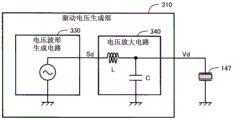
Fig. 5 is a block diagram showing an example of the configuration of the driving voltage generating unit.
Fig. 6 is a graph showing operation characteristics of the embodiment.
Fig. 7 is a perspective view showing a driving mechanism including the piezoelectric driving device according to the second embodiment.
Fig. 8 is a plan view of a second piezoelectric vibration module of the second embodiment.
Fig. 9 is a perspective view showing a robot according to another embodiment.
Description of the reference numerals
100. 100a··piezoelectric vibrator; 110. Vibrating part; 120. Support; 130. Connection; 140··piezoelectric vibration module; 147. 147A to 147E; 150. Piezoelectric vibration module; 157 piezoelectric elements; 160. Contacts; 180. Pickup electrode; 200. Console; 210 spring members; 220 driven parts; 222. Surface; 300. Drive circuit; 310 drive voltage generation unit; 320 vibration detecting unit; 330 voltage waveform generation circuit; 340 voltage amplifying circuit; 400. 400a··piezoelectric driving means; 1000. Robot; 1010 · a base; 1020. An arm; 1030. An arm; 1040. An arm; 1050. An arm; 1060. An arm; 1070. An arm; 1080 robot control unit; 1090. End effector.
Detailed Description
< first embodiment >
Fig. 1 is a perspective view showing a driving mechanism including a piezoelectric driving device 400 according to a first embodiment. The piezoelectric driving device 400 includes a piezoelectric vibrator 100 that drives the driven member 220, and a driving circuit 300 that electrically drives the piezoelectric vibrator 100. In this example, the driven member 220 is a rotor rotatable about the rotation axis O. However, as the driven member 220, other kinds of members such as linearly movable members can be used. Further, a plurality of piezoelectric vibrators 100 may be provided for one driven member 220.
The piezoelectric vibrator 100 includes a vibrating portion 110 capable of vibrating, a supporting portion 120 supporting the vibrating portion 110, and a pair of connecting portions 130 connecting the vibrating portion 110 and the supporting portion 120. The vibration portion 110 has a substantially rectangular plate-like shape. At the tip of the vibration portion 110, a contact 160 extending from the vibration portion 110 in the X direction and contacting the driven member 220 is provided. The phrase "extending from the vibration portion 110 in the X direction" herein means that the vibration portion 110 is disposed on the X-direction side. The contact 160 is formed of, for example, a ceramic having high wear resistance, and is adhered to the vibration portion 110.
The support portion 120 of the piezoelectric vibrator 100 has a U-shape surrounding the base end side (upper end side in fig. 1) of the vibration portion 110. The support 120 is fixed to a table 200 as a support member. The stage 200 is pressed toward the driven member 220 (downward in fig. 1) by the spring member 210. The structural members of the fixed spring member 210 are not shown.
The front ends of the contacts 160 contact the surface 222 of the driven member 220. The piezoelectric vibrator 100 is pressed toward the driven member 220 by the spring member 210, and thereby the contact 160 is brought into contact with the surface 222 of the driven member 220 with a sufficient frictional force. Therefore, the sliding is suppressed, and the vibration of the vibration portion 110 can be effectively transmitted to the driven member 220 via the contact 160.
As the structure of the piezoelectric vibrator 100, various structures other than the structure shown in fig. 1 can be employed, and for example, the support portion 120 and the connection portion 130 can be omitted. In the following, for convenience of explanation, the arrangement direction of the vibration part 110 and the driven member 220 (i.e., the longitudinal direction of the vibration part 110) is referred to as a "first direction X", the thickness direction (the normal direction of the vibration surface) of the piezoelectric vibrator 100 intersecting the first direction X is referred to as a "second direction Y", and the width direction of the vibration part 110 intersecting the first direction X and the second direction Y is referred to as a "third direction Z". The plane defined by the first direction X and the third direction Z is referred to as "XZ plane". The XZ plane is parallel to the surface of the piezoelectric vibrator 100. Preferably, the three directions X, Y, Z are orthogonal to each other.
The piezoelectric vibrator 100 has a plurality of piezoelectric vibration modules 140 stacked in the second direction Y. In the example of fig. 1, the number of piezoelectric vibration modules 140 is three. The plurality of piezoelectric vibration modules 140 are bonded by an electrically insulating bonding member such as an adhesive. However, the piezoelectric vibrator 100 may be constituted by one piezoelectric vibration module 140.
The plurality of piezoelectric vibration modules 140 are connected to the driving circuit 300. The driving circuit 300 includes a driving voltage generating unit 310 and a vibration detecting unit 320. The driving voltage generating unit 310 has a function of supplying a driving voltage to a piezoelectric element (described later) of the piezoelectric vibrator 100. The vibration detecting unit 320 is connected to a pickup electrode (described later) of the piezoelectric vibrator 100, and has a function of detecting vibration of the piezoelectric vibrator 100. The driving voltage generating unit 310 adjusts the frequency of the driving voltage based on the vibration detection signal Sv supplied from the pickup electrode to the vibration detecting unit 320, and supplies the driving voltage to the piezoelectric element. The operation of the driving circuit 300 will be described later.
Fig. 2 is a plan view showing an example of the piezoelectric vibration module 140. The vibration section 110 of the piezoelectric vibration module 140 includes five piezoelectric elements 147A to 147E. The pair of piezoelectric elements 147A and 147E located on one diagonal line of the rectangular vibrating portion 110 simultaneously expand and contract in the X direction, and bending vibration is generated in the vibrating portion 110. The other pair of piezoelectric elements 147B and 147D located on the other diagonal line of the vibration section 110 also simultaneously expands and contracts in the X direction, and bending vibration is generated in the vibration section 110. However, the expansion and contraction of one pair of piezoelectric elements 147A, 147E and the expansion and contraction of the other pair of piezoelectric elements 147B, 147D are preferably 180 degrees out of phase. The piezoelectric element 147C located at the center of the vibration part 110 in the width direction expands and contracts in the X direction, and causes the vibration part 110 to vibrate longitudinally in the X direction.
Each of the piezoelectric elements 147A to 147E includes a piezoelectric body (not shown) and two electrodes (not shown) sandwiching both sides of the piezoelectric body. Examples of the constituent material of the piezoelectric body include ceramics such as lead zirconate titanate (PZT), barium titanate, lead titanate, potassium niobate, lithium tantalate, sodium tungstate, zinc oxide, barium Strontium Titanate (BST), bismuth strontium tantalate (SBT), lead metaniobate, and lead scandium niobate. The piezoelectric body made of piezoelectric ceramics may be formed of a bulk material, for example, or may be formed by a sol-gel method or a sputtering method. As a constituent material of the piezoelectric body, polyvinylidene fluoride, crystal, or the like may be used in addition to the piezoelectric ceramics described above.
The piezoelectric vibration module 140 also has two pickup electrodes 180. The pickup electrode 180 is an electrode for detecting vibration of the piezoelectric vibrator 100 and supplying a vibration detection signal Sv (fig. 1) to the drive circuit 300. In the example of fig. 2, the pickup electrodes 180 are provided on the upper side and the lower side of the piezoelectric element 147C located in the center of the vibration portion 110, respectively. However, only one pickup electrode 180 may be provided, and the pickup electrode 180 may be omitted.
Fig. 3 is a schematic diagram showing a form of vibration of the piezoelectric vibration module 140. The piezoelectric vibration module 140 can vibrate in such a manner as to make the contact 160 move elliptically. This elliptical motion is achieved by the following actions: the bending vibration generated by the expansion and contraction of the pair of piezoelectric elements 147A, 147E and the expansion and contraction of the other pair of piezoelectric elements 147B, 147D, or the longitudinal vibration "bending vibration" generated by the expansion and contraction of the central piezoelectric element 147C is vibration in which the piezoelectric vibration module 140 bends in an S-shape as shown in fig. 3 in the plane of the piezoelectric vibration module 140. The "longitudinal vibration" is vibration stretching along the longitudinal direction (first direction X) of the piezoelectric vibration module 140. The piezoelectric vibrator 100 also vibrates in the same manner as the piezoelectric vibration module 140. The four piezoelectric elements 147A, 147B, 147D, 147E generate bending vibrations, which are referred to as "first piezoelectric elements". The piezoelectric element 147C generates longitudinal vibration, which is referred to as a "second piezoelectric element". The number of the first piezoelectric elements 147A, 147B, 147D, 147E or the second piezoelectric element 147C is an example, and the number of the first piezoelectric elements and the second piezoelectric elements can be set to other values as appropriate. For example, one pair of the first piezoelectric elements 147A, 147B may be omitted, and bending may be generated by the other pair of the first piezoelectric elements 147D, 147E.
Fig. 4 shows an example of waveforms of driving voltages supplied to the piezoelectric elements 147A to 147E. A driving voltage V1 is applied to the pair of piezoelectric elements 147A and 147E, a driving voltage V2 is applied to the piezoelectric element 147C, and a driving voltage V3 is applied to the other pair of piezoelectric elements 147B and 147D. The driving voltage V3 is changed in phase by pi (=180 degrees) from the driving voltage V1, and is substantially equivalent to the driving voltage V1. These driving voltages V1 and V3 are driving voltages for generating bending vibration of the piezoelectric vibration module 140, and are referred to as "first driving voltages". The driving voltage V2 is a driving voltage for generating longitudinal vibration of the piezoelectric vibration module 140, and is referred to as a "second driving voltage". The frequencies of the first driving voltages V1 and V3 and the frequency of the second driving voltage V2 are generally set to equal values.
The piezoelectric vibration module 140 vibrates in such a manner that the contact 160 performs an elliptical motion by a combination of bending vibration and longitudinal vibration (fig. 3). In this way, by expanding and contracting the pair of piezoelectric elements 147A and 147E, the other pair of piezoelectric elements 147B and 147D, and the piezoelectric element 147C in different phases, the contact 160 can be vibrated along the elliptical orbit. However, if the contact 160 can be vibrated along an elliptical orbit, the waveform of the driving voltage of the piezoelectric vibration module 140 can use various waveforms other than the waveform shown in fig. 4. For example, the driving voltage may include a dc component in addition to an ac component. In this case, "frequency of driving voltage" means frequency of ac component thereof.
As shown in fig. 2, the pickup electrode 180 is preferably arranged at a position on the central axis CX of the piezoelectric vibrator 100 extending along the first direction X in a plan view. The central axis CX is located at a position corresponding to the central axis of the vibration unit 110 in a plan view. If the pickup electrode 180 is disposed at a position on the central axis CX of the piezoelectric vibrator 100, the influence of bending vibration is reduced, and there is an advantage in that the longitudinal vibration can be accurately and easily detected. The pickup electrode 180 is also preferably disposed at any one of the sections n1, n2, n3 of bending vibration. In the example of fig. 2, the node n1 of the bending vibration exists in the center of the vibration portion 110, and the other two nodes n2, n3 exist at positions near the end portions of the vibration portion 110 on the central axis CX. If the pickup electrode 180 is disposed at any one of the sections n1, n2, n3 of the bending vibration, the influence of the bending vibration can be further reduced, and thus there is an advantage in that the longitudinal vibration of the piezoelectric vibrator 100 can be more easily detected. However, the pickup electrode 180 may be disposed at a position other than these positions.
Fig. 5 is a block diagram showing an example of the configuration of the driving voltage generating unit 310. The driving voltage generation unit 310 includes: a voltage waveform generation circuit 330 that generates a voltage waveform signal Sd having a voltage waveform of the drive voltage Vd; and a voltage amplifying circuit 340 amplifying the voltage of the voltage waveform signal Sd to generate the driving voltage Vd. The driving voltage Vd is supplied to the piezoelectric element 147, and the piezoelectric element 147 is driven. In the example of fig. 5, the voltage amplifying circuit 340 is constituted by a resonance circuit (more specifically, LC series resonance circuit). However, the voltage amplifying circuit 340 may be a circuit capable of amplifying the voltage of the voltage waveform signal Sd, and may have other various configurations. For example, the voltage amplifying circuit 340 may be constituted by an operational amplifier.
The driving voltage Vd generated by the driving voltage generating section 310 corresponds to any one of the three driving voltages V1 to V3 shown in fig. 4. The driving circuit 300 may have three driving voltage generating units 310 shown in fig. 5 to generate the driving voltages V1 to V3. Alternatively, the driving circuit 300 may generate the driving voltages V1 to V3 shown in fig. 4 by a phase adjustment circuit that adjusts the phase of the driving voltage Vd generated by the driving voltage generating unit 310 shown in fig. 5. Hereinafter, the operation of the piezoelectric driving device 400 will be described with the driving voltage Vd generated by the driving voltage generating unit 310 as driving voltages V1 to V3 representing fig. 4.
Fig. 6 is a graph showing the operation characteristics of the first embodiment. The horizontal axis is the frequency of the driving voltage Vd (fig. 5). The broken line shows the displacement Dc of the piezoelectric vibrator 100 in the stopped state. The displacement amount Dc in the stopped state is the largest in the resonance frequency fr1 (first resonance frequency) of the piezoelectric vibrator 100 in the stopped state. The solid line shows the displacement Dd of the piezoelectric vibrator 100 in the driving state. The displacement Dd in the driving state is the largest in the resonance frequency fr2 (second resonance frequency) of the piezoelectric vibrator 100 in the driving state. The dashed line shows the driving speed Sp. The driving speed Sp represents the speed at which the driven member 220 is driven. The driving speed Sp is at a maximum resonance frequency fr2 in the driving state.
As shown in fig. 6, the piezoelectric vibrator 100 is configured such that the resonance frequency fr1 in the stopped state is higher than the resonance frequency fr2 in the driven state. As described in fig. 1, since the piezoelectric vibrator 100 is pressed against the driven member 220 by the spring member 210, the contact 160 is pressed against the driven member 220 in the stopped state. In this case, the resonance frequency fr1 in the stopped state is generally higher than the resonance frequency fr2 in the driven state. However, the same effect can be obtained by a method other than the spring member 210. In the present embodiment, it is assumed that the resonance frequency of the longitudinal vibration of the piezoelectric vibrator 100 is equal to the resonance frequency of the bending vibration. In the case where the two are different, the resonance frequencies fr1, fr2 shown in fig. 6 are defined by the resonance frequency of the longitudinal vibration.
When the drive circuit 300 starts from the stopped state, the drive circuit starts driving by setting the drive frequency of the drive voltage Vd to a first frequency f1 closer to the resonance frequency fr1 in the stopped state than the resonance frequency fr2 in the driving. In the driving state after the start, the driving circuit 300 sets the driving frequency of the driving voltage Vd to a frequency smaller than the first frequency f1, and the driving frequency is closer to the second frequency f2 of the driving state than the resonance frequency fr1 of the stopped state. In this way, since the piezoelectric vibrator 100 is driven at a frequency close to the resonance frequency of the machine at the time of starting and in the driving state, the driven member 220 can be driven with a large force.
The driving frequency applied to the driving of the piezoelectric element 147 changes according to the state of the driven member 220, the ambient temperature, and the like. In order to generate a high driving force by the piezoelectric driving device 400, it is desirable to perform driving control so as to follow the driving frequency adapted to such a situation. Therefore, it is preferable to down-scan the driving frequency from the frequency f1 at the time of start to the frequency f2 of the driving state. In this way, an appropriate driving frequency can be smoothly set in accordance with various situations. Further, the operation from the start time to the drive state can be smoothly shifted.
The dot-dash line of fig. 6 shows the voltage amplification Av of the voltage amplification circuit 340 (fig. 5). The voltage amplification Av has a maximum peak at the frequency f0, decreasing as one moves away from the frequency f 0. At voltageIn the case where the amplifying circuit 340 is configured as a resonance circuit, the frequency f0 is equal to the resonance frequency of the voltage amplifying circuit 340. For example, in the case where the voltage amplification circuit 340 is configured by an LC resonance circuit, the resonance frequency f0 is
As described above, at the time of starting, the piezoelectric element 147 is driven at the first frequency f1, and is driven at the second frequency f2 in the driven state thereafter. The voltage amplification Av of the second frequency f2 in the driving state is set lower than the voltage amplification Av of the first frequency f1 at the time of starting. In other words, the voltage amplification Av of the first frequency f1 is high compared to the voltage amplification Av of the second frequency f2. With such a characteristic, the driven member can be started with a large force at the time of starting, and the driven member 220 can be driven without an excessive force in the driving state after starting.
In the present embodiment, the voltage amplification circuit 340 is configured as a circuit having a resonance frequency f0 higher than the first frequency f1, and by this circuit configuration, the characteristic that the voltage amplification factor Av of the second frequency f2 in the driving state is lower than the voltage amplification factor Av of the first frequency f1 at the time of starting is realized. However, other circuit configurations may be used to realize the preferable characteristics of the voltage amplification factors Av of the two frequencies f1 and f2. On the other hand, if the voltage amplification circuit 340 is configured to have a resonance frequency f0 higher than the driving frequency f1 at the time of startup, there are the following advantages: when the driving frequency is downsampled from the first frequency f1 to the second frequency f2, the driving voltage Vd can be smoothly reduced.
Further, it is preferable that a value of a preferable driving frequency of the driving state is determined according to the vibration detection signal Sv (fig. 1) supplied from the pickup electrode 180 to the driving circuit 300. For example, in the driving state after the start, the frequency of the driving voltage Vd can be adjusted so that the phase difference between the driving voltage Vd supplied to the piezoelectric element 147 and the vibration detection signal Sv detected by the pickup electrode 180 becomes a predetermined preferable value. Alternatively, the frequency of the driving voltage Vd may be adjusted so that the amplitude of the vibration detection signal Sv is sufficiently large.
As described above, in the piezoelectric driving device 400 according to the first embodiment, the piezoelectric vibrator 100 is configured such that the resonance frequency fr1 in the stopped state is higher than the second resonance frequency in the driving state. In addition, the driving circuit 300 starts driving by setting the driving frequency of the driving voltage Vd to a first frequency f1 closer to the resonance frequency fr1 in the stopped state than the resonance frequency fr2 in the driven state when starting from the stopped state, and sets the driving frequency of the driving voltage Vd to a second frequency f2 closer to the resonance frequency fr2 in the driven state than the resonance frequency fr1 in the stopped state in the driven state after starting. As a result, the piezoelectric vibrator 100 is driven at a frequency close to the mechanical resonance frequencies fr1 and fr2 at the time of starting and in the driving state, and therefore the driven member 220 can be driven with a large force.
< other embodiments >
Fig. 7 is a perspective view showing a driving mechanism including a piezoelectric driving device 400a according to the second embodiment. The piezoelectric driving device 400a differs from the first embodiment in the point where the second piezoelectric vibration module 150 is arranged between the plurality of piezoelectric vibration modules 140, and has the same other configuration as the first embodiment. That is, although three piezoelectric vibration modules 140 are stacked in the second direction Y in the above-described fig. 1, in the second embodiment shown in fig. 7, a second piezoelectric vibration module 150 having a different structure from the two first piezoelectric vibration modules 140 is arranged between them.
Fig. 8 is a plan view of a second piezoelectric vibration module 150 of the second embodiment. The second piezoelectric vibration module 150 has one piezoelectric element 157 disposed so as to expand over substantially the entire area of the vibration portion 110. The piezoelectric element 157 generates longitudinal vibration, similar to the piezoelectric element 147C (fig. 2) disposed in the center of the first piezoelectric vibration module 140, and corresponds to "the second piezoelectric element". Accordingly, the piezoelectric element 157 can be supplied with the same driving voltage as the driving voltage V2 (fig. 4) supplied to the piezoelectric element 147C. In the second embodiment, the second piezoelectric vibration module 150 generates the longitudinal vibration, and the piezoelectric element 147C of the first piezoelectric vibration module 140 (fig. 2) may be omitted. The piezoelectric driving device 400a according to the second embodiment also has the same effects as those of the piezoelectric driving device 400 according to the first embodiment.
Fig. 9 is a perspective view showing a robot according to another embodiment. The robot 1000 is a six-axis robot, and includes a base 1010 fixed to the ground or a ceiling, arms 1020, 1030, 1040, 1050, 1060, 1070 rotatably coupled to the base 1010, and a robot control unit 1080 for controlling driving of the arms 1020, 1030, 1040, 1050, 1060, 1070. The arm 1070 is provided with a hand connection portion, and an end effector 1090 corresponding to a task performed by the robot 1000 is attached to the hand connection portion. In addition, a piezoelectric driving device 400 is mounted in all or part of each joint, and the arms 1020, 1030, 1040, 1050, 1060, 1070 are rotated by driving the piezoelectric driving device 400. Further, the driving of each piezoelectric driving device 400 is controlled by the robot control unit 1080. The piezoelectric driving device 400 is mounted on the end effector 1090, and can be used for driving the end effector 1090. Since the robot 1000 includes the piezoelectric driving device 400, the above-described effects of the piezoelectric driving device 400 can be enjoyed.
In the above-described various embodiments, the configuration in which the piezoelectric driving device is applied to the robot has been described, but the piezoelectric driving device can be applied to various devices other than the same.
Claims (8)
1. A piezoelectric driving device is characterized in that a driven member is driven,
the piezoelectric driving device includes:
a piezoelectric vibrator; and
a driving circuit that electrically drives the piezoelectric vibrator;
the piezoelectric vibrator includes:
a contact that contacts the driven member; and
a piezoelectric element that generates vibration in accordance with a driving voltage supplied from the driving circuit,
the first resonance frequency of the longitudinal vibration of the piezoelectric vibrator in a state where the driven member is stopped is higher than the second resonance frequency of the longitudinal vibration of the piezoelectric vibrator in a state where the driven member is driven,
at the time of starting from the stopped state, the driving circuit sets the driving frequency of the driving voltage to a first frequency, which is closer to the first resonance frequency among the first resonance frequency and the second resonance frequency, to thereby start driving,
in the activated driving state, the driving circuit sets a driving frequency of the driving voltage to a second frequency that is closer to the second resonance frequency among the first resonance frequency and the second resonance frequency.
2. The piezoelectric driving device according to claim 1, wherein,
the piezoelectric vibrator is pressed against the driven member by a spring member.
3. The piezoelectric driving device according to claim 1 or 2, wherein,
the driving circuit sets the value of the driving voltage in the driving state to be lower than the value of the driving voltage at the time of the start.
4. The piezoelectric driving device according to claim 1 or 2, wherein,
the driving circuit downsamples the driving frequency from the first frequency to the second frequency.
5. The piezoelectric driving device according to claim 4, wherein,
the driving circuit has:
a voltage waveform generation circuit that generates a voltage waveform signal having a voltage waveform of the drive voltage; and
a voltage amplifying circuit for amplifying the voltage of the voltage waveform signal to generate the driving voltage,
the voltage amplification circuit is configured such that a voltage amplification factor of the first frequency is higher than a voltage amplification factor of the second frequency.
6. The piezoelectric driving device according to claim 5, wherein,
the voltage amplifying circuit has a resonance frequency, and the resonance frequency is higher than the first frequency.
7. A driving method of a piezoelectric driving device is characterized in that,
the piezoelectric driving device has a piezoelectric vibrator,
the piezoelectric vibrator includes:
a contact that contacts the driven member; and
a piezoelectric element that generates vibration according to a driving voltage,
the piezoelectric vibrator is configured such that a first resonance frequency of longitudinal vibration of the piezoelectric vibrator in a state where the driven member is stopped is higher than a second resonance frequency of longitudinal vibration of the piezoelectric vibrator in a state where the driven member is driven,
at the time of starting from the stopped state, the driving frequency of the driving voltage is set to a first frequency closer to the first resonance frequency among the first resonance frequency and the second resonance frequency, thereby starting driving,
in the post-start driving state, a driving frequency of the driving voltage is set to a second frequency closer to the second resonance frequency among the first resonance frequency and the second resonance frequency.
8. A robot is characterized by comprising:
the piezoelectric driving device according to any one of claims 1 to 6.
Applications Claiming Priority (2)
| Application Number | Priority Date | Filing Date | Title |
|---|---|---|---|
| JP2017-146029 | 2017-07-28 | ||
| JP2017146029A JP7035358B2 (en) | 2017-07-28 | 2017-07-28 | Piezoelectric drive device, drive method of piezoelectric drive device, and robot |
Publications (2)
| Publication Number | Publication Date |
|---|---|
| CN109309459A CN109309459A (en) | 2019-02-05 |
| CN109309459B true CN109309459B (en) | 2023-05-12 |
Family
ID=65138061
Family Applications (1)
| Application Number | Title | Priority Date | Filing Date |
|---|---|---|---|
| CN201810833525.1A Active CN109309459B (en) | 2017-07-28 | 2018-07-26 | Piezoelectric driving device, driving method of piezoelectric driving device, and robot |
Country Status (3)
| Country | Link |
|---|---|
| US (1) | US11203040B2 (en) |
| JP (1) | JP7035358B2 (en) |
| CN (1) | CN109309459B (en) |
Families Citing this family (2)
| Publication number | Priority date | Publication date | Assignee | Title |
|---|---|---|---|---|
| JP7500963B2 (en) * | 2019-12-20 | 2024-06-18 | セイコーエプソン株式会社 | Piezoelectric drive device control method, piezoelectric drive device, and robot |
| JP7388174B2 (en) * | 2019-12-20 | 2023-11-29 | セイコーエプソン株式会社 | Control method of piezoelectric drive device, piezoelectric drive device, and robot |
Family Cites Families (9)
| Publication number | Priority date | Publication date | Assignee | Title |
|---|---|---|---|---|
| JP2912241B2 (en) * | 1985-11-20 | 1999-06-28 | 株式会社ニコン | Ultrasonic motor using ultrasonic vibration |
| US4743788A (en) | 1985-11-20 | 1988-05-10 | Nippon Kogaku K. K. | Input frequency control device for surface acoustic wave motor |
| JPH04322179A (en) * | 1991-04-22 | 1992-11-12 | Matsushita Electric Ind Co Ltd | Method of driving ultrasonic motor |
| US7485485B2 (en) | 2004-02-09 | 2009-02-03 | Microvision, Inc. | Method and apparatus for making a MEMS scanner |
| US7247970B2 (en) * | 2004-07-02 | 2007-07-24 | Seiko Epson Corporation | Drive method for piezoelectric actuator, drive apparatus for piezoelectric actuator, electronic device, control program for drive apparatus for piezoelectric actuator, and recording medium |
| JP4795162B2 (en) * | 2006-08-09 | 2011-10-19 | オリンパス株式会社 | Ultrasonic motor and vibration detection method of ultrasonic motor |
| JP5776270B2 (en) * | 2011-03-29 | 2015-09-09 | セイコーエプソン株式会社 | Piezoelectric actuators, motors, robot hands and robots |
| JP5884303B2 (en) | 2011-06-07 | 2016-03-15 | セイコーエプソン株式会社 | Piezoelectric actuator, robot hand, and robot |
| JP6442913B2 (en) | 2014-08-13 | 2018-12-26 | セイコーエプソン株式会社 | Piezoelectric drive device, robot, and drive method thereof |
-
2017
- 2017-07-28 JP JP2017146029A patent/JP7035358B2/en active Active
-
2018
- 2018-07-26 CN CN201810833525.1A patent/CN109309459B/en active Active
- 2018-07-27 US US16/047,150 patent/US11203040B2/en active Active
Also Published As
| Publication number | Publication date |
|---|---|
| US11203040B2 (en) | 2021-12-21 |
| JP2019030092A (en) | 2019-02-21 |
| CN109309459A (en) | 2019-02-05 |
| US20190030567A1 (en) | 2019-01-31 |
| JP7035358B2 (en) | 2022-03-15 |
Similar Documents
| Publication | Publication Date | Title |
|---|---|---|
| US7898146B2 (en) | Drive unit | |
| JP5127293B2 (en) | Drive device | |
| JP2006346830A (en) | Micro mechanical device, micro switch, variable capacity capacitor, high frequency circuit and optical switch | |
| KR20110083600A (en) | Semi-resonant driving systems and methods thereof | |
| CN109309459B (en) | Piezoelectric driving device, driving method of piezoelectric driving device, and robot | |
| US7994687B2 (en) | Piezoelectric actuator and method for driving the same | |
| US8183738B2 (en) | Control system for oscillatory actuator | |
| CN113014136B (en) | Control method of piezoelectric driving device, and robot | |
| JP5760748B2 (en) | Piezoelectric actuator driving method and driving unit | |
| JP2020072532A (en) | Piezoelectric drive device, robot, and printer | |
| CN113014135B (en) | Control method of piezoelectric driving device, and robot | |
| US20170003500A1 (en) | Drive apparatus | |
| US11824469B2 (en) | Method for sensing abnormality of piezoelectric drive device, piezoelectric drive device, and robot | |
| JP5315434B2 (en) | Drive device | |
| JP6554845B2 (en) | Piezoelectric driving device, robot and driving method thereof | |
| JP2018037507A (en) | Vibrator, piezoelectric actuator, piezoelectric motor, robot, and electronic component transfer device | |
| JP2021191049A (en) | Piezoelectric drive device, piezoelectric motor and robot | |
| JP2020127332A (en) | Method for adjusting piezoelectric drive device, piezoelectric drive device, and robot | |
| JP6455017B2 (en) | Piezoelectric driving device and driving method thereof, robot and driving method thereof | |
| JP2005102368A (en) | Driving device | |
| JP2014003736A (en) | Piezoelectric motor and driving method of the same | |
| JPH03203571A (en) | Piezoelectric actuator |
Legal Events
| Date | Code | Title | Description |
|---|---|---|---|
| PB01 | Publication | ||
| PB01 | Publication | ||
| SE01 | Entry into force of request for substantive examination | ||
| SE01 | Entry into force of request for substantive examination | ||
| GR01 | Patent grant | ||
| GR01 | Patent grant |