CN109227851B - Automatic assembling equipment for wooden door frame - Google Patents
Automatic assembling equipment for wooden door frame Download PDFInfo
- Publication number
- CN109227851B CN109227851B CN201810885944.XA CN201810885944A CN109227851B CN 109227851 B CN109227851 B CN 109227851B CN 201810885944 A CN201810885944 A CN 201810885944A CN 109227851 B CN109227851 B CN 109227851B
- Authority
- CN
- China
- Prior art keywords
- conveyor belt
- conveying
- limit switch
- detection sensor
- frame
- Prior art date
- Legal status (The legal status is an assumption and is not a legal conclusion. Google has not performed a legal analysis and makes no representation as to the accuracy of the status listed.)
- Active
Links
Images


Classifications
-
- B—PERFORMING OPERATIONS; TRANSPORTING
- B27—WORKING OR PRESERVING WOOD OR SIMILAR MATERIAL; NAILING OR STAPLING MACHINES IN GENERAL
- B27M—WORKING OF WOOD NOT PROVIDED FOR IN SUBCLASSES B27B - B27L; MANUFACTURE OF SPECIFIC WOODEN ARTICLES
- B27M3/00—Manufacture or reconditioning of specific semi-finished or finished articles
- B27M3/18—Manufacture or reconditioning of specific semi-finished or finished articles of furniture or of doors
-
- B—PERFORMING OPERATIONS; TRANSPORTING
- B27—WORKING OR PRESERVING WOOD OR SIMILAR MATERIAL; NAILING OR STAPLING MACHINES IN GENERAL
- B27M—WORKING OF WOOD NOT PROVIDED FOR IN SUBCLASSES B27B - B27L; MANUFACTURE OF SPECIFIC WOODEN ARTICLES
- B27M3/00—Manufacture or reconditioning of specific semi-finished or finished articles
- B27M3/0013—Manufacture or reconditioning of specific semi-finished or finished articles of composite or compound articles
- B27M3/0086—Manufacture or reconditioning of specific semi-finished or finished articles of composite or compound articles characterised by connecting using glue
Landscapes
- Engineering & Computer Science (AREA)
- Life Sciences & Earth Sciences (AREA)
- Manufacturing & Machinery (AREA)
- Wood Science & Technology (AREA)
- Forests & Forestry (AREA)
- Automatic Assembly (AREA)
Abstract
Automatic equipment of assembling of wooden door frame, the pier transport assembly on A includes A right side, A left side conveyer belt and AA barrier mechanism. The B side yard and frame conveying assembly includes a B left conveying belt and a front, middle and back B right conveying belts and is located in front of the A wharf conveying assembly. And the wharf conveying assembly under the C comprises a left conveying belt, a middle conveying belt, a right conveying belt and a stop mechanism, and is positioned in front of the side yard B and the frame conveying assembly. The D conveying preassembly assembly comprises a left conveying belt D, a right conveying belt D, a portal frame D, a D positioning device with the rear end suspended above the right conveying belt B in the middle and a D pushing device extending and suspended above the middle conveying belt C. The E glass box conveying assembly is provided with E conveying belt assemblies, and conveying belt wheels of the E conveying belt assemblies are connected through an E transmission shaft. And a manipulator is arranged on the frame assembly F. The G glue supply system is positioned in front of the F frame assembly.
Description
Technical Field
The invention belongs to wooden door processing equipment, and particularly relates to automatic assembling equipment for a wooden door frame.
Background
In the production of the existing wood door frame, the processing procedures of a left side court, a right side court, an upper dock, a lower dock, a filling plate, a crosspiece, a filling plate assembly, a glass box and the like are mainly manually or semi-automatically dispersed and processed, and then the wood door frame is manually inspected and warehoused. When the wooden door frame is assembled, qualified semi-finished products are conveyed out of a warehouse to an assembling station manually according to the model and specification of the products, then the semi-finished products are placed on an assembling workbench, are clamped through some simple tools, are subjected to corresponding manual gluing, and are assembled semi-automatically. The semi-automatic assembling production method of the wooden door frame has the defects of low production efficiency, high cost, unstable quality, high error rate, high labor intensity and poor production adaptability, is difficult to meet the requirement of mass personalized customization in the modern market, and is further incapable of meeting the requirement of modern intelligent digital production.
Disclosure of Invention
The invention mainly aims to provide automatic assembling equipment for a wooden door frame, so that the requirement of mass personalized customization in the modern market can be met and the requirement of modern intelligent digital production can be met.
The technical scheme adopted by the invention is as follows: the utility model provides an automatic equipment of assembling of wooden door frame, includes that pier transport assembly, B limit court and frame transport assembly, pier transport assembly under C, D transport preassembly assembly, E glass box transport assembly, F frame assembly, G supply gluey system. In the wharf conveying assembly on the conveyor belt A, the left end and the right end of the right conveyor belt A are adjacent to the right end of the left conveyor belt B and the AA blocking mechanism respectively. The B-side yard and frame conveying assembly comprises a front B right conveying belt, a middle B right conveying belt and a rear B right conveying belt. The left end of the middle B right conveyor belt is adjacent to the right end of the B left conveyor belt, and the rear end of the rear B right conveyor belt is adjacent to the right end of the A left conveyor belt, the front ends of the A right conveyor belt and the A blocking mechanism. In the wharf conveying assembly under the conveyor belt C, the left end and the right end of the conveyor belt in the conveyor belt C are adjacent to the left end of the conveyor belt C and the left end of the conveyor belt C respectively, and the right end of the conveyor belt C is adjacent to the material stopping mechanism C. The right end of the middle conveying belt C, the rear ends of the right conveying belt C and the stop mechanism C are adjacent to the front end of the right conveying belt B in front. In the D conveying preassembly assembly, the right end of the D left conveying belt is adjacent to the left end of the D right conveying belt, the front end of the D pushing device is fixed in front of the right end of the D right conveying belt through a D portal frame, and the rear end of the D pushing device extends through the right end of the D right conveying belt and is suspended above the middle B right conveying belt. The D material pushing device is positioned above the right end of the right conveying belt and below the D material pushing device, and the rear end of the D material pushing device extends and is suspended above the middle conveying belt C. In the E glass box conveying assembly, an E conveying belt component is arranged between every two E lifting roller components which move back and forth, and conveying belt wheels at the front ends of the E conveying belt components are connected through an E transmission shaft. A front pair of supporting legs of an F portal frame in the F frame assembly are fixed on the right side of the D pushing device and the right front of the D right conveyor belt, a rear pair of supporting legs of the F portal frame are fixed behind the A right conveyor belt, and a plurality of manipulators are arranged on the F frame assembly. The E glass box conveying assembly is fixed at the rear end of the F frame assembly, and the G glue supply system is positioned on the right side of the D portal frame and in front of the F frame assembly.
Here, when a person stands in front of the quay conveyor assembly under C facing the present invention, the side close to the person is defined as "front", the corresponding side away from the person is defined as "rear", the left-hand side of the person is defined as "left", and the right-hand side of the person is defined as "right".
Drawings
FIG. 1: the invention is a general diagram and a schematic diagram of the structure;
FIG. 2: a, a schematic diagram of an upper wharf conveying assembly;
FIG. 3: b, a schematic diagram of a courtyard and a frame conveying assembly;
FIG. 4: c, a schematic view of a wharf conveying assembly;
FIG. 5: d, conveying a preassembly schematic diagram;
FIG. 6: d, conveying a schematic diagram of a part I in the preassembly assembly;
FIG. 7: d, conveying a first secondary component in the component I in the preassembly assembly;
FIG. 8: d, conveying a second secondary part in the part I in the preassembly assembly;
FIG. 9: d, a schematic structural diagram of a material pushing device;
FIG. 10: e, a schematic diagram of a glass box conveying assembly;
FIG. 11: e, a structural schematic diagram of a component I in the glass box conveying assembly;
FIG. 12: e, a structural schematic diagram of a component II in the glass box conveying assembly;
FIG. 13: e, a schematic structural diagram of a component III in the glass box conveying assembly;
FIG. 14: f, a schematic diagram of a frame assembly;
FIG. 15: a part of the FB manipulator I is in a structural schematic diagram;
FIG. 16: the FB mechanical arm I is partially shown in a second structural schematic diagram; :
FIG. 17: the FC mechanical arm II is in a schematic structure diagram;
FIG. 18: a part of FD manipulator III is a schematic structural diagram;
FIG. 19: a second structural schematic diagram of the FD manipulator III part;
FIG. 20: and the FA manipulator IV is structurally schematic.
Detailed Description
The technical scheme of the invention is further specifically described by the following embodiments and the accompanying drawings.
As shown in fig. 1-20, the present invention comprises an upper wharf conveyor assembly 1, a side wharf and frame conveyor assembly 2, a lower wharf conveyor assembly 3, a D conveyor pre-assembly 4, an E glass box conveyor assembly 5, an F frame assembly 6, and a G glue supply system 7. Since each part of the whole machine contains a plurality of identical parts or small parts, in order to distinguish which large part these parts or small parts belong to, the large part which is first indicated by A, B, C, D, E, F, G letters before the name of each large part to indicate the number behind the large part is the second part of the whole machine, and the second part is only one difference in description and does not represent the importance of the parts represented by the large parts. Similarly, FA manipulator iv and FB manipulator i respectively represent two different manipulators in the F frame assembly, that is, FA manipulator iv represents manipulator iv as the first small part in the F frame assembly, and FB manipulator i represents manipulator i as the second manipulator in the F frame assembly. The other meanings of the indications are analogized, and therefore they are not described in detail here.
In the wharf-on-A conveying assembly, the left end and the right end of a right conveyor belt 1.4A are respectively adjacent to the right end of a left conveyor belt 1.1A and an AA blocking mechanism 1.5;
the B-side yard and frame conveying assembly comprises a front conveying belt 2.2, a middle conveying belt 2 and a rear conveying belt 2.2, wherein the left end of the middle conveying belt B is adjacent to the right end of the left conveying belt 2.1, and the rear end of the rear conveying belt B is adjacent to the right end of the left conveying belt A, the right conveying belt A and the front end of the AA blocking mechanism;
in the wharf conveying assembly below the C, the left end and the right end of a conveying belt 3.3 in the C are respectively adjacent to the right end of a left conveying belt 3.1 in the C and the left end of a right conveying belt 3.5 in the C, and the right end of the right conveying belt in the C is adjacent to a stop mechanism 3.6 in the C; the right end of the middle conveyor belt, the rear ends of the right conveyor belt and the stop mechanism are adjacent to the front end of the right conveyor belt in the front B;
in the D conveying preassembly assembly 4, the right end of a D left conveying belt 4.1 is adjacent to the left end of a D right conveying belt 4.3, the front end of a D pushing device 4.5 is fixed in front of the right end of the D right conveying belt through a D portal frame 4.51, the rear end of the D pushing device extends through the right end of the D right conveying belt and is suspended above a middle B right conveying belt, a D pushing device 4.6 is positioned above the right end of the D right conveying belt and below the D pushing device, and the rear end of the D pushing device extends above a middle C conveying belt;
in the E glass box conveying assembly 5, an E conveying belt of an E conveying belt assembly is arranged between every two rollers of the E lifting roller assembly in the front-back direction, and conveying belt wheels at the front end of each E conveying belt are connected through an E transmission shaft; a centering mechanism and a detection device driven by a cylinder 5.3 are arranged above the lifting roller, a lifting gear component driven by the cylinder 5.5 is arranged above an E flat belt component 5.1 on the right side of the lifting roller component, a lifting gear rod component 5.6 driven by a cylinder 5.11 is arranged at the right end of the E flat belt component 5.1, and the front end of the E glass box conveying assembly is positioned at the rear lower part of the F frame assembly and adjacent to the rear part of the A right conveying belt.
A front pair of supporting legs of an F portal frame 6.1 in an F frame assembly are fixed on the right side of a D centering positioning device 4.6 and in front of a C right conveyor belt, a rear pair of supporting legs of the F portal frame 6.1 are fixed on the rear side of an A right conveyor belt and two sides of the front section of an E glass box conveying assembly, three manipulators I6.3, II 6.6 and III 6.7 which move forward and backward are arranged on the F frame assembly portal frame 6.1, and two manipulators IV 6.5 which operate a gluing mechanism along the forward and backward movement are oppositely arranged on the left inner side and the right inner side of the F frame assembly portal frame 6.1.
The G glue supply system is positioned at the right side of the D portal frame and in front of the F frame assembly.
Wherein:
as shown in fig. 1 and 2, the right end of the left conveyor belt a is provided with an AB blocking mechanism 1.2, the front end of the upper end of 1.8 on the AA frame is provided with an AA detection sensor C1.1 on the left side of the AB blocking mechanism, the middle part of the rear end of the upper end of 1.7 on the AB frame is provided with an AB detection sensor C1.2, the middle part of the front end of the upper end on the AB frame is provided with an a glue coating mechanism 1.3, and the upper end of the AA blocking mechanism is provided with an AC detection sensor C1.3.
As shown in fig. 1 and 3, the B-side yard and frame conveying assembly further includes a BA blocking finger 2.3, a BB blocking finger 2.4, a BC blocking finger 2.5, a BD blocking finger 2.6, a BE blocking finger 2.7, a BF blocking finger 2.8, a BG blocking finger 2.9, a BH blocking finger 2.10, a BI blocking finger 2.11, a BJ blocking finger 2.12, a BK blocking finger 2.13, a BL blocking finger 2.14, a BM blocking finger 2.15, a BA limit switch X2.1, a BB limit switch X2.2, a BC limit switch X2.3, a BD limit switch X2.4, a BE limit switch X2.5, and a BF limit switch X2.6. The BK material blocking fingers are arranged on the front side of the right end of the rear B right conveyor belt rack 2.16, the BM material blocking fingers are arranged on the rear side of the right end of the front B right conveyor belt rack, the BA, BC, BE, BG, BH and BL material blocking fingers are arranged on the front side of the middle B right conveyor belt rack from left to right, and the BB, BD, BF, BI and BJ material blocking fingers are arranged on the rear side of the middle B right conveyor belt rack from left to right; the BA limit switch X2.1 is arranged on the right side of the front end of the B left conveyor belt frame 2.17, and the BB, BC, BD, BE and BF limit switches are arranged on the rear side of the front B right conveyor belt frame.
As shown in fig. 1 and 4, the lower wharf conveying assembly further includes a C blocking mechanism 3.2, a C glue coating mechanism 3.4, a CA detection sensor C3.1, a CB detection sensor C3.2, a CC detection sensor C3.3, and a CD detection sensor C3.4. The C stock stop is arranged at the upper end of the C stock stop support 3.7, and the CD detection sensor is arranged on the C stock stop. The C right conveyor belt is arranged on a C right conveyor belt lifting frame 3.8. The rear side of conveyer belt support 3.9 right-hand member links to each other in C rubber coating mechanism and C, and CB detects the sensor and links to each other with the front side of conveyer belt support right-hand member in C. The lower ends of the front end and the rear end of the C blocking mechanism are respectively connected with the front side and the rear side of the right end of the C left conveyor belt bracket 3.10, and the front ends of the CA detection sensor and the right end of the C left conveyor belt bracket 3.10 are connected with the left side of the C blocking mechanism.
As shown in fig. 1 and 5-9, the D conveying pre-assembly further includes a D stock stop 4.2, a D glue applying mechanism 4.4, a D material pushing device 4.5, a D centering positioning device 4.6, a DA frame 4.7, a DC conveyor belt 4.8, a DB frame 4.9, a DC frame 4.10, a DA detection sensor C4.1, a DB detection sensor C4.2, and a DC detection sensor C4.3. The D material pushing device further comprises a D portal frame 4.51, a D cantilever beam 4.52, a DA cylinder 4.53, a D support 4.54, a D pinch roller set 4.55, a DA linear guide rail pair 4.56, a D servo driver 4.57, a D carriage 4.58, a DB cylinder 4.59, a D swing arm 4.510, a D push rod 4.511, a DC detection sensor C4.51, a DD detection sensor C4.52 and a DE detection sensor C4.53;
the front and the back two D portal frames are fixed in front of the right end of the D right conveyor belt in sequence, the front end of a D cantilever beam is connected with the lower side of the front D portal frame, the middle end of the D cantilever beam is connected with the lower side of the back D portal frame, a D support is connected with the right side of the back end of the D cantilever beam, the cylinder body of a DA cylinder is connected with the D support, the piston of the DA cylinder is connected with a D pressing wheel group, a D dragging plate is connected with the lower side of the front end of the D cantilever beam, a D servo driver is arranged on the lower side of the front end of the D cantilever beam and the back side of the D dragging plate, the D servo driver is connected with the D dragging plate, a DB cylinder is connected with the D dragging plate, one end of a D swing arm is connected with the D servo driver, the other end, the DC detection sensor is positioned in front of the DD detection sensor, and the DE detection sensor is arranged at the rear end of the D cantilever;
the D centering positioning device further comprises a DA fixing frame 4.61, a DA shift rod 4.62, a DB shift rod 4.63, a DB linear guide rail pair 4.65, a D connecting plate 4.66, a DA baffle 4.67, a DC cylinder 4.68, a DB fixing frame 4.69, a D supporting plate 4.610, a DB baffle 4.611, a DA shift rod fixing seat 4.612, a D fixing guide groove 4.613, a DD cylinder assembly (comprising a cylinder, an air pipe, a cylinder fixing frame and other components) 4.614, a D lifting plate 4.615, a D synchronous pulley 4.616, a D locking block 4.617, a DC linear guide rail pair 4.618, a DC cylinder 4.619, a D connecting locking block 4.620, a D synchronous belt 4.621, a DB shift rod fixing seat 4.622, a DA detection sensor C4.61, a DB limit switch X4.62, a DC limit switch X4.63 and a DC limit switch X4.64. The mutual positions and the connection relations of the above components in the centering positioning device are shown in fig. 6, and are not described in detail herein; the D left conveyor belt is installed on the DC rack 4.10, the D right conveyor belt is installed on the DB rack 4.9, the DA rack 4.7 is fixed below the D cantilever beam 4.52 at the front end of the D pushing device 4.5, the DC conveyor belt 4.8 is installed on the DA rack, the D centering positioning device is installed at the upper end of the DA rack, and the DC conveyor belt is installed above the left end of the D pushing device; the D blocking mechanism 4.2 is arranged at the right end of the DC rack 4.10, and the lower ends of the front end and the rear end of the D blocking mechanism are fixedly connected with the DC rack; the DA detection sensor C4.1 and the front end of the DC frame are fixedly connected to the left side of the D blocking mechanism 4.2; the D glue coating mechanism 4.4 is connected with the front end of the DB rack, the D glue coating mechanism is positioned on the left side of the DA rack, the rear ends of the DC detection sensor and the DB rack are connected with the positions opposite to the connecting positions of the D glue coating mechanism and the front end of the DB rack, and the front ends of the DB detection sensor and the DB rack are connected with the left side of the DB rack;
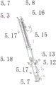
the composition of the delivery pre-assembly will be described in more detail with reference to fig. 1, 5, 6, 7, 8, and 9, which will not be described in further detail herein. As shown in fig. 1 and 10-13, the E glass box conveying assembly further includes an EA cylinder 5.3, an E lifting plate 5.4, an EB cylinder 5.5, an E stop lever component 5.6, an E synchronous pulley 5.7, an E locking block 5.8, an EA bracket 5.9, an EB bracket 5.10, an EC cylinder 5.11, an E fixing plate 5.12, an E linear guide rail pair 5.13, an ED cylinder 5.14, an E synchronous belt 5.15, an E displacement sensor 5.16, an E material pushing plate 5.17, an E moving bracket 5.18, an E motor 5.20, an EC bracket 5.21, an E base frame 5.22, an EA detection sensor C5.1, an EB detection sensor C5.2, and an EC detection sensor C5.3;
the detailed structure of the components and the mutual position and connection relationship among the components of the E glass box conveying assembly are shown in figures 1, 10, 11, 12 and 13, and will not be described in detail. As shown in fig. 1 and 14-20, the manipulators arranged on the F frame assembly are respectively an FA manipulator iv 6.5, an FB manipulator i 6.3, an FC manipulator ii 6.6 and an FD manipulator iii 6.7, which are all arranged on an F gantry 6.1, wherein the number of the FA manipulators iv is four; an FA rack 6.2, an FA linear guide rail pair 6.4, an FA limit switch X6.1, an FB limit switch X6.2, an FC limit switch X6.3, an FD limit switch X6.4, an FE limit switch X6.5, an FF limit switch X6.6, an FG limit switch X6.7, an FH limit switch X6.8 and an FI limit switch X6.9 are also arranged on the F portal frame 6.1;
an FA crossbeam 6.31 is arranged on an FB manipulator I6.3, an FA support 6.32, an FB cylinder 6.319, an FA linear guide rail pair 6.312, an FB linear guide rail pair 6.322, an FA servo driver 6.316, an FJ limit switch X6.31, an FK limit switch X6.32, an FL limit switch X6.33 are arranged on the FA crossbeam 6.31, a bearing seat is arranged on the FA support 6.32, an FA transmission shaft 6.33 is arranged on the bearing seat, an FB servo driver 6.34, an FB linear guide rail pair 6.315 and an FA cylinder 6.314 are arranged on the FC support 6.39, an FA push plate 6.313 is arranged on the FB linear guide rail pair 6.315, an FA transmission shaft 6.33 is arranged on the FB linear guide rail pair 3634, a gear is arranged on the FA transmission shaft 6.33, an FA base 6.320 is arranged on the FA linear guide rail pair 6.312, an FD support 6.35, an FE support 6.37, an FB 6.310, an FB cylinder 6.319, a rack 6.321, an FD support 6.35 is arranged on the FD support 6.35, an FC limit switch X6.34, an FC cylinder 6.38 and an FD cylinder 6.317.38 are arranged on the FC linear guide rail pair, an FD push plate 6.311 is arranged on the FD cylinder 6.38, an FA pressure plate 6.318 is arranged on the FB cylinder 6.319, an FB rack 6.321 is arranged on the FB linear guide rail pair 6.322, and a gear is arranged on the FA servo driver 6.316;
the FC manipulator II 6.6 is provided with an FB beam 6.61, the FB beam 6.61 is provided with an FF support 6.62 and an FG support 6.66, the FF support 6.62 is provided with an FC servo driver 6.63, the FC servo driver 6.63 is provided with a gear, the FG support 6.66 is provided with an FC linear guide rail pair 6.65 and an FC cylinder 6.67, the FC linear guide rail pair 6.65 is provided with an F support 6.68, the F support 6.68 is provided with an FE linear guide rail pair 6.64 and an F fixed seat 6.614, the FE linear guide rail pair 6.64 is provided with an F moving seat 539 6.69, the F fixed seat 2 is provided with an FD cylinder 6.613, the F moving seat 6.69 is provided with an FE cylinder 6.610 and an FE push plate 6.611, and the FE cylinder 6.610 is;
FD manipulator III 6.7 is provided with FC crossbeam 6.71, FC crossbeam 6.71 is provided with FH support 6.72, FI support 6.75, FC linear guide rail pair 6.710, FD servo driver 6.714, FE linear guide rail pair 6.720, FO limit switch X6.71, FP limit switch X6.72, FQ limit switch X6.73, FH support 6.72 is provided with a bearing seat, FI support 6.75 is provided with FE servo driver 6.74, FF cylinder 6.712, FD linear guide rail pair 6.713, FE servo driver 6.74 is provided with FB transmission shaft 6.73, FB transmission shaft 6.73 is provided with a gear, FD linear guide rail pair 6.713 is provided with FF push plate 6.711, FC linear guide rail pair 6.710 is provided with FB seat 6.718, FB seat 6.718 is provided with FJ support 6.76, FG push plate 6.79, FD servo driver 6.714, FG 6.717, FJ support 6.76 is provided with FH cylinder 6.77 and FR limit switch X6.74, FH cylinder 6.77 is provided with FH cylinder 3878, FG cylinder 4642 is provided with FG push plate 3, FC servo switch X6.42 is provided with FF, a rack is arranged on the FF linear guide rail pair 6.719;
the FA manipulator IV 6.5 is provided with an F fixing plate 6.51, an FC rack 6.52, an FG linear guide rail pair 6.53, an FS limit switch X6.51, an FT limit switch X6.52, an FU limit switch X6.53, an FV limit switch X6.54, an FA detection sensor C6.51 and an FB detection sensor C6.52 are arranged on the F fixing plate 6.51, an F moving arm 6.54 is arranged on the FG linear guide rail pair 6.53, an F linear module 6.55 and an FG servo driver 6.56 are arranged on the F moving arm 6.54, an FI cylinder 6.57 is arranged on the F linear module 6.55, and an F glue coating mechanism 6.58 is arranged on the FI cylinder 6.57; the F linear module 6.55 is provided with an FC detection sensor C6.53 and an FD detection sensor C6.54;
the components and the structure and connection relationship of the components on the frame assembly are shown in fig. 1, 14-20, and will not be described in detail. Preferably, each of the above conveyor belts is a flat belt.
The working process of the invention is as follows:
the power supply is started, the MES issues an order plan to the upper computer, the upper computer decomposes the order into an equipment task and issues the equipment task to the PLC, the PLC controls equipment processing according to the issued equipment task parameters, meanwhile, the PLC feeds back the processed task information to the upper computer, and the upper computer monitors the task completion condition and the equipment running state.
Starting a power supply, starting conveying of a left conveyor belt 1.1 and a right conveyor belt 1.4, releasing an AB blocking mechanism 1.2, stopping conveying of an AA blocking mechanism 1.5 in an ascending mode, starting working gluing of the A gluing mechanism 1.3 while stopping conveying of the AB blocking mechanism 1.2 when the AB detection sensor C1.2 detects that materials are in place, stopping conveying of the A left conveyor belt 1.1 when the AA detection sensor C1.1 detects that materials are in place, stopping working gluing of the A gluing mechanism 1.3 while releasing of the AB blocking mechanism 1.2 when the AB detection sensor C1.2 detects that no materials are in place, starting conveying of the A left conveyor belt 1.1, descending the AA blocking mechanism 1.5 while stopping conveying of the A left conveyor belt 1.1 and the A right conveyor belt 1.4 when the AC detection sensor C1.3 detects that materials are in place, and enabling an A wharf conveying assembly 1 to be in place to wait for final assembly;
starting a power supply, starting conveying of a left conveyor belt 2.1 and a front, middle and rear B right conveyor belt 2.2, stopping conveying of the left conveyor belt 2.1 when a BA limit switch X2.1 detects materials, stopping conveying of the left conveyor belt 2.1 when a BB limit switch X2.2 and a BC limit switch X2.3 detect that the materials are in place, starting corresponding working positions of the material stopping fingers 2.3, 2.4, 2.5, 2.6 and 2.7 of BA, BB, BC, BD and BE, stopping conveying of the front, middle and rear B right conveyor belts, and positioning of a frontier to a total preassembling station;
starting a power supply, carrying out work conveying on a DC conveyor belt 4.8, when a DA detection sensor C4.61 detects that materials are in place, stopping conveying on the DC conveyor belt 4.8, driving a DA shift rod 4.62 and a DB shift rod 4.63 to move in the middle by a DC cylinder 4.619 working out [ connecting a locking block 4.620, a D synchronous belt 4.621, a D locking block 4.617 and a DB shift rod fixing seat 4.622 ] and centering a material filling plate, then driving a DB cylinder 4.59 to work out, swinging a D swing arm 4.510 downwards, stopping the material by a D push rod 4.511, driving a D push rod 4.511 to move forwards by a D carriage 4.58 ], pushing the filling plate to corresponding set positions on three B right conveyor belts 2.2, retracting the DB cylinder 4.59 to work, reversely working by a D servo driver 4.57, detecting a DD detection sensor C4.52 in place, stopping the D servo driver 4.57, positioning the D push rod 4.511 to return to a total zero position, and pushing the filling plate to a total zero position; starting a power supply, judging whether a crosspiece and a filler plate combined prefabricated part are installed or not according to the MES order dispatching requirement, if the crosspiece and the filler plate combined prefabricated part are needed to be installed, a left conveyor belt 4.1 and a right conveyor belt 4.3 work and convey, a D blocking mechanism 4.2 is released, a cylinder in a DD cylinder component 4.614 works and extends out, a D lifting plate 4.615 rises to a blocking position, when a DB detection sensor C4.2 detects that materials are in place, a D gluing mechanism 4.4 starts to work and glue (simultaneously the D blocking mechanism 4.2 blocks the materials), when a DA detection sensor C4.1 detects that the materials are in place, the left conveyor belt 4.1 stops conveying, when a DB detection sensor C4.2 detects that no materials exist, the D gluing mechanism 4.4 stops working and glue (simultaneously the D blocking mechanism 4.2 is released), the left conveyor belt 4.1 starts to convey, and an FA limit switch X4.62 detects that the materials are conveyed in place, a DC cylinder 4.68 works and extends out, a DA baffle 4.67 and a right conveyor belt 4.3 stops working, meanwhile, when the DC conveyor belt 4.8 works and conveys, and the DA detection sensor C4.61 detects that the materials are in place, the DC conveyor belt 4.8 stops conveying, the DC cylinder 4.619 works and extends out (through the D connection locking block 4.620, the D synchronous belt 4.621, the D locking block 4.617 and the DB gear rod fixing seat 4.622) drive the DA gear rod 4.62 and the DB gear rod 4.63 to move in the middle and center the material crosspiece and the filling plate, then the DB cylinder 4.59 works and extends out, the D swing arm 4.510 swings downwards, the D push rod 4.511 stops, the D servo driver 4.57 works (through the D carriage 4.58) drive the D push rod 4.511 to move forwards to push the material to be pre-installed, the limit switches DCX4.63 and the DD limit switch X4.64 detect that the materials are in place, the D servo driver 4.57 stops working, the crosspiece and the filling plate are pre-installed to form a crosspiece and filling plate combined prefabricated part, the DC cylinder 4.619 and the DD cylinder assembly 4.614 work and retract simultaneously, the DA gear rod 4.63 and the DB gear rod returns to the zero position and returns to the lifting, the D servo driver 4.57 works again to push the crosspiece and the filler plate combined prefabricated members to the corresponding total preassembly stations on the three B right conveyor belts 2.2, the D servo driver 4.57 works reversely and the DB air cylinder 4.59 works and retracts, when the DD detection sensor C4.52 detects that the crosspiece and the filler plate combined prefabricated members are in place, the D servo driver 4.57 stops working, the D push rod 4.511 returns to the zero position, and the crosspiece and the filler plate combined prefabricated members are positioned to the total preassembly stations. If the assembling prefabricated member of the crosspiece and the filler plate is not needed, the process is omitted;
starting a power supply, carrying out work conveying on three B right conveyor belts 2.2, simultaneously conveying a atrium, a filling plate, a crosspiece and a filling plate combined prefabricated part of a total preassembly station to a total assembly station, detecting materials in place by BD, DE and BF limit switches X2.4, X2.5 and X2.6, positioning the materials to the total assembly station, stopping conveying the three B right conveyor belts 2.2, an FI cylinder 6.57, lowering a glue gun of an F glue coating mechanism 6.58 to a working position, an F linear module 6.55, a glue gun of an F glue coating mechanism 6.58 to move along a Y axis, detecting a FC detection sensor C6.53 to be in place, stopping the F linear module 6.55, adjusting the glue gun of the F linear module 6.58 to move to the glue coating station to carry out glue coating while moving the glue gun of the FG 6.56.58, and setting a servo actuator (a servo actuator) to move the glue coating gun 6.54, a glue coating arm to move along the glue coating 6.6.54 and a glue coating arm to set the F linear module 6.6.6.58, after the gluing is finished, an FG servo driver 6.56, an F linear module 6.55 and an FI cylinder 6.57 work in reverse directions, an FD detection sensor C6.54 detects that the module is in place, the F linear module 6.55 stops working, an FS limit switch X6.51 and an FU limit switch X6.53 detect that the module returns to place, an FG servo driver 6.56 stops working, a glue gun of an F gluing mechanism 6.58 returns to a zero position, BF, BG, BH, BI, BJ, BK, BL, BM stop fingers 2.8, 2.9, 2.10, 2.11, 2.12, 2.13, 2.14 and 2.15 work and retract, the positioning is removed, and a border, a filling plate, a crosspiece and a filling plate are combined to wait for final assembly;
starting a power supply, a C left conveyor belt 3.1, a C middle conveyor belt 3.3 and a C right conveyor belt 3.5 work and convey, a C blocking mechanism 3.2 is released, a C blocking mechanism 3.6 ascends to block materials, when a CB detection sensor C3.2 detects materials in place, a C gluing mechanism 3.4 starts to work and glue, and simultaneously the C blocking mechanism 3.2 blocks materials, when a CA detection sensor C3.1 detects materials in place, the C left conveyor belt 3.1 stops conveying, when the CB detection sensor C3.2 detects no materials, the C gluing mechanism 3.4 stops working and glue, simultaneously the C blocking mechanism 3.2 releases, the C left conveyor belt 3.1 starts to convey, when the CC detection sensor C3.3 detects materials in place, the C right conveyor belt 3.5 stops conveying, a lifting mechanism drives the C right conveyor belt 3.5 to ascend to a working position, the C right conveyor belt 3.5 works and conveys again, when a CD detection sensor detects materials in place, the C blocking mechanism C3.6 descends, and simultaneously stops conveying the C3.1 and the C3.3.3.5 middle conveyor belt, the wharf is put to wait for final assembly;
starting a power supply, judging whether a glass box needs to be loaded according to the MES order dispatching requirement, if the glass box needs to be loaded, working and conveying a transmission belt in an E conveyor belt component 5.1, working and extending an EC cylinder 5.11, descending and releasing an E stop lever component 5.6, working and outputting an EB cylinder 5.5, descending and stopping an E lifting plate 5.4, when an EA detection sensor C5.1 detects a material, stopping feeding at the front end, when an EB detection sensor C5.2 detects the material, stopping conveying the transmission belt in the E conveyor belt component 5.1, working and extending an ED cylinder 5.14, lifting a E roller component 5.2 in place, working and extending an EA cylinder 5.3, driving an E synchronous belt 5.15 to move through an E moving frame 5.18, driving E locking blocks 5.8 at two sides to move, driving E locking blocks 5.8 at two sides to drive an E material pushing plate 5.17 to move in the middle, and driving a slip ring of an E synchronous belt displacement sensor 5.16 to move through the E moving frame 5.18 to detect the size of the material, after centering, the EA cylinder 5.3 retracts, the E material pushing plates 5.17 at two ends return to the zero position, the ED cylinder 5.14 retracts, the E lifting roller assembly 5.2 descends to return to the zero position, a transmission belt in the E conveyor belt assembly 5.1 conveys materials in a working mode, when an EC detection sensor C5.3 detects that materials exist, the EC cylinder 5.11 retracts in a working mode, the E stop lever assembly 5.6 ascends to stop materials, the transmission belt in the E conveyor belt assembly 5.1 stops conveying, the glass box waits for general assembly, and if the glass box does not need to be assembled, the process is omitted;
the final assembly mode is different according to different types of door types: the prefabricated member assembled by the upper wharf, the side courtyard, the filling plate, the crosspiece and the filling plate and the lower wharf are taken as an example for explanation;
starting a power supply, according to the MES order dispatching requirement, working of FA, FF, FD, FC cylinders 6.314, 6.712, 6.613 and 6.67 is extended, an FE cylinder 6.610 is retracted, a baffle 6.313 and an FF push plate 6.711 are lowered to a pushing position, an FE push plate 6.611 and an FB press plate 6.612 are in zero positions, FB, FE and FC servo drivers 6.34, 6.74 and 6.63 work simultaneously, an FB manipulator I6.3, an FD manipulator III 6.7 and an FC manipulator II 6.6 move to a set position, the FE servo drivers 6.74 and the FC servo drivers 6.63 stop working simultaneously, the FE cylinder 6.610 works to extend, the FB press plate 6.612 is pressed to the working position, the edge is pressed, the FD cylinder 6.613 works to retract, the FE push plate 6.611 pushes the edge to the set position, the FA cylinder 6.314 and the FC cylinder 6.712 are retracted, the baffle 6.313 and the FF push plate 6.711 are raised to the zero position, the FB cylinder 6.319 and the FB cylinder 6.717 works to extend, the FA press plate 6.318 and four corners of the FA press plate 6.716, the workpieces, the FA cylinder 3934 and the FE servo drivers 34, 6.74, 6.316 and 6.714 work simultaneously, FB, FD, FC, FI and FG push plates 6.310, 6.311, 6.317, 6.78 and 6.79 move inwards simultaneously, the combined prefabricated member of the upper wharf, the filling plate, the crosspiece and the filling plate and the lower wharf are pressed inwards simultaneously, FM, FN and FR limit switches X6.34, X6.35 and X6.74 detect that the materials are in place, FB, FE, FA and FD servo drivers 6.34, 6.74, 6.316 and 6.714 stop working simultaneously, the size of a door is judged according to the walking displacement of FB, FE, FA, FD servo drivers 6.34, 6.74, 6.316 and 6.714, unqualified alarm is removed, qualified pressure maintaining preset time is set, after the pressure maintaining is finished, FB, FG cylinders 6.319 and 6.717 work is retracted, FA, FC pressure plates 6.318 and 6.716 are lifted back, FD cylinders 6.613 work is extended and FE, FC cylinders 6.610 and 6.67 work is retracted, FE 6.34 and 6.612 and FB, FG, FI, FG and FG push plates are moved back, FD drivers, 6.38, 6.612, FD drivers, 3638 and FD are operated in reverse directions, FB. FS, FH, FK, FP limit switches X6.2, X6.5, X6.8, X6.32, X6.72 detect in-place, FB, FC, FE, FA, FD servo drivers 6.34, 6.63, 6.74, 6.316, 6.714 stop moving back to zero, and the final assembly is completed.
The invention adopts high integration of informatization and industrialization, implements intelligent digital mass personalized customization flexible production, can realize automatic adjustment and compatibility of various products with multiple specifications, and can realize full-automatic completion of loading, positioning, assembling and detecting blanking, digital management and unmanned production in the whole process, and has strong production adaptability, good product consistency, high production efficiency, low cost, environmental friendliness, safety and reliability. The application of the invention can greatly improve the competitiveness of the product in domestic and international markets, drive the transformation and upgrade of the industry and promote the technical innovation of peripheral industries.
The above embodiments are merely preferred embodiments of the present invention, and not intended to limit the structure and scope of the invention. Indeed, many equivalent variations in the shapes, constructions and design objectives of the devices according to the present invention are possible. Therefore, all equivalent changes in the shapes, structures and design objectives of the present invention are intended to be covered by the present invention, and all such equivalent changes are intended to be protected by the present invention.
Claims (7)
1. The utility model provides an automatic equipment of assembling of wooden door frame, the characteristic is: the device comprises an upper wharf conveying assembly, a side wharf conveying assembly B, a frame conveying assembly, a lower wharf conveying assembly C, a conveying preassembly assembly D, a glass box conveying assembly E, a frame assembling assembly F and a glue supply system G;
the left end and the right end of a right conveyor belt A in the wharf loading conveying assembly A are respectively adjacent to the right end of a left conveyor belt A and an AA blocking mechanism;
the B-side yard and frame conveying assembly comprises a front conveying belt, a middle conveying belt and a rear conveying belt B, wherein the left end of the middle conveying belt B is adjacent to the right end of the left conveying belt B, and the rear end of the rear conveying belt B is adjacent to the right end of the left conveying belt A, the right conveying belt A and the front end of the blocking mechanism A;
the left end and the right end of a conveyor belt in the wharf conveying assembly C are respectively adjacent to the right end of a left conveyor belt and the left end of a right conveyor belt in the wharf conveying assembly C, and the right end of the right conveyor belt in the wharf conveying assembly C is adjacent to a material stopping mechanism C; the right end of the middle conveyor belt, the rear ends of the right conveyor belt and the stop mechanism are adjacent to the front end of the right conveyor belt in the front B;
the right end of a left conveyor belt D in the D conveying preassembly assembly is adjacent to the left end of a right conveyor belt D, the front of the right conveyor belt D is connected with the rear end of a DC conveyor belt, the front end of a material pushing device D is fixed in front of the right end of the right conveyor belt D through a portal frame D, the rear end of the material pushing device D extends through the right end of the right conveyor belt D and is suspended above a right conveyor belt B in the middle, the material pushing device D is positioned above the right end of the right conveyor belt D and below the material pushing device D, and the rear end of the material pushing device D extends above the conveyor belt C;
an E conveying belt of an E conveying belt assembly is arranged between every two rollers of the E lifting roller assembly in the front-back direction in the E glass box conveying assembly, the conveying belt wheels at the front ends of the E conveying belts are connected through an E transmission shaft, and the front end of the E glass box conveying assembly is positioned at the rear lower part of the F frame assembly and adjacent to the rear part of the right conveying belt A;
a front pair of supporting legs of an F portal frame in the F frame assembly are fixed on the right side of the D centering positioning device and the right front of the C right conveyor belt, a rear pair of supporting legs of the F portal frame are fixed on the rear side of the A right conveyor belt and two sides of the front section of the E glass box conveying assembly, and a plurality of manipulators are arranged on the F frame assembly;
the G glue supply system is positioned in front of the D portal frame and the F frame assembly.
2. The automatic assembling equipment for the wooden door frame according to claim 1, characterized in that: the right-hand member of A left side conveyer belt is equipped with AB blocking mechanism, and the upper end in the AA frame is equipped with AA detection sensor in AB blocking mechanism's left side, and the upper end in the AB frame is equipped with AB detection sensor and A rubber coating mechanism, and AA blocking mechanism's upper end is equipped with AC detection sensor.
3. The automatic assembling equipment for the wooden door frame according to claim 1, characterized in that: the B-side yard and frame conveying assembly further comprises a BA material blocking finger, a BB material blocking finger, a BC material blocking finger, a BD material blocking finger, a BE material blocking finger, a BF material blocking finger, a BG material blocking finger, a BH material blocking finger, a BI material blocking finger, a BJ material blocking finger, a BK material blocking finger, a BL material blocking finger, a BM material blocking finger, a BA limit switch, a BB limit switch, a BC limit switch, a BD limit switch, a BE limit switch and a BF limit switch; the BK material blocking fingers are arranged on the front side of the right end of the rear B right conveyor belt rack, the BM material blocking fingers are arranged on the rear side of the right end of the front B right conveyor belt rack, the BA, BC, BE, BG, BH and BL material blocking fingers are arranged on the front side of the middle B right conveyor belt rack from left to right, and the BB, BD, BF, BI and BJ material blocking fingers are arranged on the rear side of the middle B right conveyor belt rack from left to right; the BA limit switch is arranged on the right side of the front end of the B left conveyor belt frame, and the BB, BC, BD, BE and BF limit switch is arranged on the rear side of the front B right conveyor belt frame.
4. The automatic assembling equipment for the wooden door frame according to claim 1, characterized in that: the lower wharf conveying assembly further comprises a C blocking mechanism, a C gluing mechanism, a CA detection sensor, a CB detection sensor, a CC detection sensor and a CD detection sensor; the C stock stop is arranged at the upper end of the C stock stop bracket, and the CD detection sensor is arranged on the C stock stop; the right conveyor belt C is arranged on the right conveyor belt C lifting frame; the glue coating mechanism C is connected with the rear side of the right end of the middle conveyor belt bracket C, and the CB detection sensor is connected with the front side of the right end of the middle conveyor belt bracket C; the lower ends of the front end and the rear end of the C blocking mechanism are respectively connected with the front side and the rear side of the right end of the C left conveyor belt bracket, and the front ends of the CA detection sensor and the right end of the C left conveyor belt bracket are connected with the left side of the C blocking mechanism.
5. The automatic assembling equipment for the wooden door frame according to claim 1, characterized in that: the D conveying preassembly assembly also comprises a D blocking mechanism, a D gluing mechanism, a D centering positioning device, a DA frame, a DC conveyor belt, a DB frame, a DC frame, a DA detection sensor, a DB detection sensor and a DC detection sensor;
the D pushing device also comprises a D portal frame, a D cantilever beam, a DA cylinder, a D support, a D pressing wheel group, a DA linear guide rail pair, a D servo driver, a D planker, a DB cylinder, a D swing arm, a D push rod, a DC detection sensor, a DD detection sensor and a DE detection sensor;
the front and the back two D portal frames are fixed in front of the right end of the D right conveyor belt in sequence, the front end of a D cantilever beam is connected with the lower side of the front D portal frame, the middle end of the D cantilever beam is connected with the lower side of the back D portal frame, a D support is connected with the right side of the back end of the D cantilever beam, the cylinder body of a DA cylinder is connected with the D support, the piston of the DA cylinder is connected with a D pressing wheel group, a D dragging plate is connected with the lower side of the front end of the D cantilever beam, a D servo driver is arranged on the lower side of the front end of the D cantilever beam and the back side of the D dragging plate, the D servo driver is connected with the D dragging plate, a DB cylinder is connected with the D dragging plate, one end of a D swing arm is connected with the D servo driver, the other end, the DC detection sensor is positioned in front of the DD detection sensor, and the DE detection sensor is arranged at the rear end of the D cantilever;
the D left conveyor belt is installed on the DC rack, the D right conveyor belt is installed on the DB rack, the DA rack is fixed below a D cantilever beam of the D pushing device, the DC conveyor belt is installed at the upper end of the DA rack, and the D center positioning device is installed above the DC conveyor belt of the DA rack; the D blocking mechanism is arranged at the right end of the DC frame, and the lower ends of the front end and the rear end of the D blocking mechanism are fixedly connected with the DC frame; the DA detection sensor and the front end of the DC frame are fixedly connected to the left side of the D blocking mechanism; the D glue mechanism is connected with the front end of the DB rack, the D glue mechanism is positioned on the left side of the DA rack, the rear ends of the DC detection sensor and the DB rack are connected with the positions opposite to the connecting positions of the front ends of the D glue mechanism and the DB rack, the DB detection sensor is connected with the front end of the DB rack, and the connecting position is at the left end of the front end of the DB rack.
6. The automatic assembling equipment for the wooden door frame according to claim 1, characterized in that: the manipulators arranged on the F frame assembly comprise an FA manipulator IV, an FB manipulator I, an FC manipulator II and an FD manipulator III, which are all arranged on the F portal frame, wherein the number of the FA manipulator IV is four; an FA rack, an FA linear guide rail pair, an FA limit switch, an FB limit switch, an FC limit switch, an FD limit switch, an FE limit switch, an FF limit switch, an FG limit switch, an FH limit switch and an FI limit switch are further arranged on the F portal frame;
an FA cross beam is arranged on the FB manipulator I, an FA support, an FA linear guide rail pair, an FB linear guide rail pair, an FA servo driver, an FJ limit switch, an FK limit switch and an FL limit switch are arranged on the FA cross beam, a bearing seat is arranged on the FA support, an FA transmission shaft is arranged on the bearing seat, an FB servo driver, an FB linear guide rail pair and an FA cylinder are arranged on the FC support, an FA push plate is arranged on the FB linear guide rail pair, an FA transmission shaft is arranged on the FB servo driver, a gear is arranged on the FA transmission shaft, an FA dragging seat is arranged on the FA linear guide rail pair, an FD support, an FE support, an FB push plate, an FB cylinder and an FB rack are arranged on the FA support, an FC cylinder and an FM limit switch are arranged on the FD support, an FC push plate is arranged on the FE support, an FD cylinder and an FN, a gear is arranged on the FA servo driver;
the FC manipulator II is provided with an FB beam, the FB beam is provided with an FF support and an FG support, the FF support is provided with an FC servo driver, the FC servo driver is provided with a gear, the FG support is provided with an FC linear guide rail pair and an FC cylinder, the FC linear guide rail pair is provided with an F support, the F support is provided with an FE linear guide rail pair and an F fixing seat, the FE linear guide rail pair is provided with an F moving seat, the F fixing seat is provided with an FD cylinder, the F moving seat is provided with an FE cylinder and an FE push plate, and the FE cylinder;
the FD manipulator III is provided with an FC crossbeam, an FH support, an FI support, an FC linear guide rail pair, an FD servo driver, an FE linear guide rail pair, an FO limit switch, an FP limit switch and an FQ limit switch are arranged on the FC crossbeam, a bearing seat is arranged on the FH support, an FE servo driver, an FF cylinder and an FD linear guide rail pair are arranged on the FI support, an FB transmission shaft is arranged on the FE servo driver, a gear is arranged on the FB transmission shaft, an FF push plate is arranged on the FD linear guide rail pair, an FB dragging seat is arranged on the FC linear guide rail pair, an FJ support, an FG push plate, an FD servo driver and an FG cylinder are arranged on the FB dragging seat, an FH cylinder and an FR limit switch are arranged on the FJ support, an FI push plate is arranged on the;
the FA manipulator IV is provided with an F fixing plate, an FC rack, an FG linear guide rail pair, an FS limit switch, an FT limit switch, an FU limit switch, an FV limit switch, an FA detection sensor and an FB detection sensor are arranged on the F fixing plate, an F moving arm is arranged on the FG linear guide rail pair, an F linear module and an FG servo driver are arranged on the F moving arm, an FI cylinder is arranged on the F linear module, and an F gluing mechanism is arranged on the FI cylinder; and the F linear module is provided with an FC detection sensor and an FD detection sensor.
7. The automatic assembling equipment for the wooden door frame according to any one of claims 1 to 6, characterized in that: each conveyor belt is a flat belt.
Priority Applications (1)
| Application Number | Priority Date | Filing Date | Title |
|---|---|---|---|
| CN201810885944.XA CN109227851B (en) | 2018-08-06 | 2018-08-06 | Automatic assembling equipment for wooden door frame |
Applications Claiming Priority (1)
| Application Number | Priority Date | Filing Date | Title |
|---|---|---|---|
| CN201810885944.XA CN109227851B (en) | 2018-08-06 | 2018-08-06 | Automatic assembling equipment for wooden door frame |
Publications (2)
| Publication Number | Publication Date |
|---|---|
| CN109227851A CN109227851A (en) | 2019-01-18 |
| CN109227851B true CN109227851B (en) | 2020-12-11 |
Family
ID=65070417
Family Applications (1)
| Application Number | Title | Priority Date | Filing Date |
|---|---|---|---|
| CN201810885944.XA Active CN109227851B (en) | 2018-08-06 | 2018-08-06 | Automatic assembling equipment for wooden door frame |
Country Status (1)
| Country | Link |
|---|---|
| CN (1) | CN109227851B (en) |
Families Citing this family (5)
| Publication number | Priority date | Publication date | Assignee | Title |
|---|---|---|---|---|
| CN109702828B (en) * | 2019-02-02 | 2023-09-05 | 佛山市恒途机械有限公司 | Door frame assembling machine and door frame assembling method |
| CN111391056B (en) * | 2019-10-22 | 2021-10-01 | 杭州新松机器人自动化有限公司 | Flitch concatenation and fixed length cutting unloading equipment |
| CN111360967B (en) * | 2020-03-24 | 2022-01-25 | 上海中息信息科技有限公司 | Home decoration wood fence production device |
| CN114179185B (en) * | 2021-12-17 | 2022-11-29 | 中国矿业大学 | Wooden door production line and using method |
| CN115677239B (en) * | 2023-01-04 | 2023-03-10 | 常州大诚金盾新型建材有限公司 | Automatic assembling machine for door and window machining |
Citations (8)
| Publication number | Priority date | Publication date | Assignee | Title |
|---|---|---|---|---|
| US3015348A (en) * | 1958-11-17 | 1962-01-02 | Warren B Zern | System for assembling prehung doors and jambs |
| JPH10278010A (en) * | 1997-04-07 | 1998-10-20 | Shiyouda Tekko Kk | Manufacturing device for frame member |
| GB2378476A (en) * | 2001-08-11 | 2003-02-12 | Alfred Lambert | Method for assembling doorframe with door |
| CN201385352Y (en) * | 2009-03-20 | 2010-01-20 | 大连佳林设备制造有限公司 | Full-automatic frame assembly machine |
| CN204382431U (en) * | 2014-11-28 | 2015-06-10 | 无锡市福曼科技有限公司 | A kind of timber automatic assembling machine |
| CN107336295A (en) * | 2017-07-31 | 2017-11-10 | 梦天木门集团有限公司 | A kind of energy-saving door leaf erecting production system |
| CN107571365A (en) * | 2017-10-20 | 2018-01-12 | 南通跃通数控设备有限公司 | A kind of door pocket plate machining production line |
| CN206937543U (en) * | 2017-06-12 | 2018-01-30 | 浙江梦天木业有限公司 | A kind of doorframe assembly equipment |
-
2018
- 2018-08-06 CN CN201810885944.XA patent/CN109227851B/en active Active
Patent Citations (8)
| Publication number | Priority date | Publication date | Assignee | Title |
|---|---|---|---|---|
| US3015348A (en) * | 1958-11-17 | 1962-01-02 | Warren B Zern | System for assembling prehung doors and jambs |
| JPH10278010A (en) * | 1997-04-07 | 1998-10-20 | Shiyouda Tekko Kk | Manufacturing device for frame member |
| GB2378476A (en) * | 2001-08-11 | 2003-02-12 | Alfred Lambert | Method for assembling doorframe with door |
| CN201385352Y (en) * | 2009-03-20 | 2010-01-20 | 大连佳林设备制造有限公司 | Full-automatic frame assembly machine |
| CN204382431U (en) * | 2014-11-28 | 2015-06-10 | 无锡市福曼科技有限公司 | A kind of timber automatic assembling machine |
| CN206937543U (en) * | 2017-06-12 | 2018-01-30 | 浙江梦天木业有限公司 | A kind of doorframe assembly equipment |
| CN107336295A (en) * | 2017-07-31 | 2017-11-10 | 梦天木门集团有限公司 | A kind of energy-saving door leaf erecting production system |
| CN107571365A (en) * | 2017-10-20 | 2018-01-12 | 南通跃通数控设备有限公司 | A kind of door pocket plate machining production line |
Also Published As
| Publication number | Publication date |
|---|---|
| CN109227851A (en) | 2019-01-18 |
Similar Documents
| Publication | Publication Date | Title |
|---|---|---|
| CN109227851B (en) | Automatic assembling equipment for wooden door frame | |
| CN107819134B (en) | New energy battery module assembly line | |
| CN201960197U (en) | Automatic shearing line for special-shaped plates | |
| CN109128851B (en) | Flexible automatic production line for punching, welding or bonding automobile exterior trimming parts | |
| CN104773337B (en) | Snatch formula tray automatic distribution device | |
| CN109623926B (en) | Automatic flexible production line for processing non-metal rectangular plate parts | |
| CN211140612U (en) | RGV dolly | |
| CN109079047B (en) | Automatic feeding and discharging equipment of stamping robot | |
| CN111283810A (en) | Flexible automatic production line for punching and welding automobile bumper | |
| CN113233220A (en) | Full-automatic loading and unloading system compatible with materials of multiple specifications | |
| CN211033923U (en) | Rail shuttle trolley with liftable load | |
| CN212266094U (en) | Movable automatic plate loading machine of multilayer hot press | |
| CN113245772A (en) | Automatic welding production line | |
| CN112660767A (en) | Automatic overturning and clamping cage entering system for tires | |
| CN109353797B (en) | Welding production line and processing conveying device | |
| CN113442241A (en) | Movable automatic plate loading machine of multilayer hot press | |
| CN215325761U (en) | Full-automatic loading and unloading system compatible with materials of multiple specifications | |
| CN211997501U (en) | Realize multi-direction heavy load shuttle of carrying | |
| CN212372323U (en) | Flexible automatic production line for punching and welding automobile bumper | |
| CN219483270U (en) | Car roof wet gluing mechanism with scissor lifting structure | |
| CN218950466U (en) | Automatic discharging stacking device for large-specification wooden or bamboo profiles | |
| CN110270781A (en) | A kind of bogie frame intelligence vertical library assembly welding production assembly line | |
| CN219525573U (en) | Primary and secondary tray stacking mechanism | |
| CN221369111U (en) | Large box bottom plate welding material conveying system | |
| CN212831064U (en) | Full-automatic up-down conveying conveyor belt |
Legal Events
| Date | Code | Title | Description |
|---|---|---|---|
| PB01 | Publication | ||
| PB01 | Publication | ||
| SE01 | Entry into force of request for substantive examination | ||
| SE01 | Entry into force of request for substantive examination | ||
| GR01 | Patent grant | ||
| GR01 | Patent grant |