CN1092109C - Liquid ejection method, head and apparatus - Google Patents
Liquid ejection method, head and apparatus Download PDFInfo
- Publication number
- CN1092109C CN1092109C CN97114890A CN97114890A CN1092109C CN 1092109 C CN1092109 C CN 1092109C CN 97114890 A CN97114890 A CN 97114890A CN 97114890 A CN97114890 A CN 97114890A CN 1092109 C CN1092109 C CN 1092109C
- Authority
- CN
- China
- Prior art keywords
- liquid
- pulse
- movable piece
- bubble
- fluid course
- Prior art date
- Legal status (The legal status is an assumption and is not a legal conclusion. Google has not performed a legal analysis and makes no representation as to the accuracy of the status listed.)
- Expired - Fee Related
Links
Images


Classifications
-
- B—PERFORMING OPERATIONS; TRANSPORTING
- B41—PRINTING; LINING MACHINES; TYPEWRITERS; STAMPS
- B41J—TYPEWRITERS; SELECTIVE PRINTING MECHANISMS, i.e. MECHANISMS PRINTING OTHERWISE THAN FROM A FORME; CORRECTION OF TYPOGRAPHICAL ERRORS
- B41J2/00—Typewriters or selective printing mechanisms characterised by the printing or marking process for which they are designed
- B41J2/005—Typewriters or selective printing mechanisms characterised by the printing or marking process for which they are designed characterised by bringing liquid or particles selectively into contact with a printing material
- B41J2/01—Ink jet
- B41J2/015—Ink jet characterised by the jet generation process
- B41J2/04—Ink jet characterised by the jet generation process generating single droplets or particles on demand
- B41J2/045—Ink jet characterised by the jet generation process generating single droplets or particles on demand by pressure, e.g. electromechanical transducers
- B41J2/04501—Control methods or devices therefor, e.g. driver circuits, control circuits
- B41J2/04528—Control methods or devices therefor, e.g. driver circuits, control circuits aiming at warming up the head
-
- B—PERFORMING OPERATIONS; TRANSPORTING
- B41—PRINTING; LINING MACHINES; TYPEWRITERS; STAMPS
- B41J—TYPEWRITERS; SELECTIVE PRINTING MECHANISMS, i.e. MECHANISMS PRINTING OTHERWISE THAN FROM A FORME; CORRECTION OF TYPOGRAPHICAL ERRORS
- B41J2/00—Typewriters or selective printing mechanisms characterised by the printing or marking process for which they are designed
- B41J2/005—Typewriters or selective printing mechanisms characterised by the printing or marking process for which they are designed characterised by bringing liquid or particles selectively into contact with a printing material
- B41J2/01—Ink jet
- B41J2/015—Ink jet characterised by the jet generation process
- B41J2/04—Ink jet characterised by the jet generation process generating single droplets or particles on demand
- B41J2/045—Ink jet characterised by the jet generation process generating single droplets or particles on demand by pressure, e.g. electromechanical transducers
- B41J2/04501—Control methods or devices therefor, e.g. driver circuits, control circuits
- B41J2/04563—Control methods or devices therefor, e.g. driver circuits, control circuits detecting head temperature; Ink temperature
-
- B—PERFORMING OPERATIONS; TRANSPORTING
- B41—PRINTING; LINING MACHINES; TYPEWRITERS; STAMPS
- B41J—TYPEWRITERS; SELECTIVE PRINTING MECHANISMS, i.e. MECHANISMS PRINTING OTHERWISE THAN FROM A FORME; CORRECTION OF TYPOGRAPHICAL ERRORS
- B41J2/00—Typewriters or selective printing mechanisms characterised by the printing or marking process for which they are designed
- B41J2/005—Typewriters or selective printing mechanisms characterised by the printing or marking process for which they are designed characterised by bringing liquid or particles selectively into contact with a printing material
- B41J2/01—Ink jet
- B41J2/015—Ink jet characterised by the jet generation process
- B41J2/04—Ink jet characterised by the jet generation process generating single droplets or particles on demand
- B41J2/045—Ink jet characterised by the jet generation process generating single droplets or particles on demand by pressure, e.g. electromechanical transducers
- B41J2/04501—Control methods or devices therefor, e.g. driver circuits, control circuits
- B41J2/0458—Control methods or devices therefor, e.g. driver circuits, control circuits controlling heads based on heating elements forming bubbles
-
- B—PERFORMING OPERATIONS; TRANSPORTING
- B41—PRINTING; LINING MACHINES; TYPEWRITERS; STAMPS
- B41J—TYPEWRITERS; SELECTIVE PRINTING MECHANISMS, i.e. MECHANISMS PRINTING OTHERWISE THAN FROM A FORME; CORRECTION OF TYPOGRAPHICAL ERRORS
- B41J2/00—Typewriters or selective printing mechanisms characterised by the printing or marking process for which they are designed
- B41J2/005—Typewriters or selective printing mechanisms characterised by the printing or marking process for which they are designed characterised by bringing liquid or particles selectively into contact with a printing material
- B41J2/01—Ink jet
- B41J2/015—Ink jet characterised by the jet generation process
- B41J2/04—Ink jet characterised by the jet generation process generating single droplets or particles on demand
- B41J2/045—Ink jet characterised by the jet generation process generating single droplets or particles on demand by pressure, e.g. electromechanical transducers
- B41J2/04501—Control methods or devices therefor, e.g. driver circuits, control circuits
- B41J2/04588—Control methods or devices therefor, e.g. driver circuits, control circuits using a specific waveform
-
- B—PERFORMING OPERATIONS; TRANSPORTING
- B41—PRINTING; LINING MACHINES; TYPEWRITERS; STAMPS
- B41J—TYPEWRITERS; SELECTIVE PRINTING MECHANISMS, i.e. MECHANISMS PRINTING OTHERWISE THAN FROM A FORME; CORRECTION OF TYPOGRAPHICAL ERRORS
- B41J2/00—Typewriters or selective printing mechanisms characterised by the printing or marking process for which they are designed
- B41J2/005—Typewriters or selective printing mechanisms characterised by the printing or marking process for which they are designed characterised by bringing liquid or particles selectively into contact with a printing material
- B41J2/01—Ink jet
- B41J2/015—Ink jet characterised by the jet generation process
- B41J2/04—Ink jet characterised by the jet generation process generating single droplets or particles on demand
- B41J2/045—Ink jet characterised by the jet generation process generating single droplets or particles on demand by pressure, e.g. electromechanical transducers
- B41J2/04501—Control methods or devices therefor, e.g. driver circuits, control circuits
- B41J2/04591—Width of the driving signal being adjusted
-
- B—PERFORMING OPERATIONS; TRANSPORTING
- B41—PRINTING; LINING MACHINES; TYPEWRITERS; STAMPS
- B41J—TYPEWRITERS; SELECTIVE PRINTING MECHANISMS, i.e. MECHANISMS PRINTING OTHERWISE THAN FROM A FORME; CORRECTION OF TYPOGRAPHICAL ERRORS
- B41J2/00—Typewriters or selective printing mechanisms characterised by the printing or marking process for which they are designed
- B41J2/005—Typewriters or selective printing mechanisms characterised by the printing or marking process for which they are designed characterised by bringing liquid or particles selectively into contact with a printing material
- B41J2/01—Ink jet
- B41J2/015—Ink jet characterised by the jet generation process
- B41J2/04—Ink jet characterised by the jet generation process generating single droplets or particles on demand
- B41J2/045—Ink jet characterised by the jet generation process generating single droplets or particles on demand by pressure, e.g. electromechanical transducers
- B41J2/04501—Control methods or devices therefor, e.g. driver circuits, control circuits
- B41J2/04593—Dot-size modulation by changing the size of the drop
-
- B—PERFORMING OPERATIONS; TRANSPORTING
- B41—PRINTING; LINING MACHINES; TYPEWRITERS; STAMPS
- B41J—TYPEWRITERS; SELECTIVE PRINTING MECHANISMS, i.e. MECHANISMS PRINTING OTHERWISE THAN FROM A FORME; CORRECTION OF TYPOGRAPHICAL ERRORS
- B41J2/00—Typewriters or selective printing mechanisms characterised by the printing or marking process for which they are designed
- B41J2/005—Typewriters or selective printing mechanisms characterised by the printing or marking process for which they are designed characterised by bringing liquid or particles selectively into contact with a printing material
- B41J2/01—Ink jet
- B41J2/015—Ink jet characterised by the jet generation process
- B41J2/04—Ink jet characterised by the jet generation process generating single droplets or particles on demand
- B41J2/045—Ink jet characterised by the jet generation process generating single droplets or particles on demand by pressure, e.g. electromechanical transducers
- B41J2/04501—Control methods or devices therefor, e.g. driver circuits, control circuits
- B41J2/04598—Pre-pulse
-
- B—PERFORMING OPERATIONS; TRANSPORTING
- B41—PRINTING; LINING MACHINES; TYPEWRITERS; STAMPS
- B41J—TYPEWRITERS; SELECTIVE PRINTING MECHANISMS, i.e. MECHANISMS PRINTING OTHERWISE THAN FROM A FORME; CORRECTION OF TYPOGRAPHICAL ERRORS
- B41J2/00—Typewriters or selective printing mechanisms characterised by the printing or marking process for which they are designed
- B41J2/005—Typewriters or selective printing mechanisms characterised by the printing or marking process for which they are designed characterised by bringing liquid or particles selectively into contact with a printing material
- B41J2/01—Ink jet
- B41J2/135—Nozzles
- B41J2/14—Structure thereof only for on-demand ink jet heads
- B41J2/14016—Structure of bubble jet print heads
- B41J2/14024—Assembling head parts
-
- B—PERFORMING OPERATIONS; TRANSPORTING
- B41—PRINTING; LINING MACHINES; TYPEWRITERS; STAMPS
- B41J—TYPEWRITERS; SELECTIVE PRINTING MECHANISMS, i.e. MECHANISMS PRINTING OTHERWISE THAN FROM A FORME; CORRECTION OF TYPOGRAPHICAL ERRORS
- B41J2/00—Typewriters or selective printing mechanisms characterised by the printing or marking process for which they are designed
- B41J2/005—Typewriters or selective printing mechanisms characterised by the printing or marking process for which they are designed characterised by bringing liquid or particles selectively into contact with a printing material
- B41J2/01—Ink jet
- B41J2/135—Nozzles
- B41J2/14—Structure thereof only for on-demand ink jet heads
- B41J2/14016—Structure of bubble jet print heads
- B41J2/14032—Structure of the pressure chamber
- B41J2/14048—Movable member in the chamber
-
- B—PERFORMING OPERATIONS; TRANSPORTING
- B41—PRINTING; LINING MACHINES; TYPEWRITERS; STAMPS
- B41J—TYPEWRITERS; SELECTIVE PRINTING MECHANISMS, i.e. MECHANISMS PRINTING OTHERWISE THAN FROM A FORME; CORRECTION OF TYPOGRAPHICAL ERRORS
- B41J2/00—Typewriters or selective printing mechanisms characterised by the printing or marking process for which they are designed
- B41J2/005—Typewriters or selective printing mechanisms characterised by the printing or marking process for which they are designed characterised by bringing liquid or particles selectively into contact with a printing material
- B41J2/01—Ink jet
- B41J2/135—Nozzles
- B41J2/14—Structure thereof only for on-demand ink jet heads
- B41J2/14016—Structure of bubble jet print heads
- B41J2/14032—Structure of the pressure chamber
- B41J2/14056—Plural heating elements per ink chamber
-
- B—PERFORMING OPERATIONS; TRANSPORTING
- B41—PRINTING; LINING MACHINES; TYPEWRITERS; STAMPS
- B41J—TYPEWRITERS; SELECTIVE PRINTING MECHANISMS, i.e. MECHANISMS PRINTING OTHERWISE THAN FROM A FORME; CORRECTION OF TYPOGRAPHICAL ERRORS
- B41J2202/00—Embodiments of or processes related to ink-jet or thermal heads
- B41J2202/01—Embodiments of or processes related to ink-jet heads
- B41J2202/21—Line printing
Landscapes
- Particle Formation And Scattering Control In Inkjet Printers (AREA)
- Ink Jet (AREA)
- Nozzles (AREA)
Abstract
A liquid ejection method includes preparing a head comprising an ejection outlet, a bubble generation region for generating the bubble in the liquid, a movable member disposed faced to the bubble generation region and displaceable between a first position and a second position further from the bubble generation region than the first position; displacing the movable member from the first position to the second position by pressure produced by the generation of the bubble in the bubble generating portion to permit expansion of the bubble more in a downstream side closer to the ejection outlet than in an upstream side; supplying, to a heat generating element, a driving pulse divided into a first pulse and an adjacent second pulse with interval time therebetween; pre-heating the liquid by the first pulse to an extent not enough to eject the liquid through the ejection outlet; generating a bubble by heating the liquid by the second pulse to eject the liquid through the ejection outlet; controlling a degree of pre-heating of the liquid by changing at least one of a pulse width of the first pulse or the interval time.
Description
The present invention relates to a kind of liquid discharging method and equipment thereof, wherein, the liquid of expectation is by providing heat energy to this liquid, its foaming being sprayed.
The invention particularly relates to a kind of jet head, it has the movable movable piece by foaming, a headstock that adopts this jet head, and relate to the liquid-jet device that uses jet head, the headstock.The invention still further relates to by foaming mobile movable piece and a kind of liquid discharging method and the recording method of atomizing of liquids.
The present invention can be applied to as printer, duplicator, facsimile machine with communication transmission system, literal reason device with printing portion or analog, and the equipment such as industrial tape deck that are combined into various treating apparatus, in these equipment, record carries out on as recording materials such as paper, line, fiber, yarn fabric, leather, metal, plastic resin material, glass, timber, potteries a kind of.
In present specification, " record " not only means the image that forms character, figure or analog with certain sense, comprises that also formation does not have the pattern of any certain sense.
The ink jet recording method of inkjet type of being referred to as to foam is known, in the method, the instantaneous state variation causes producing instantaneous Volume Changes (foaming) by the energy that printing ink is applied as heat, so that printing ink is sprayed from spout, make printing ink spray to recording materials and the sticking image document that produces thereon therefrom by the power that produces by state variation.As disclosed in U.S. Pat 4723129, a kind of tape deck that adopts boiling foaming recording method has the spout of an oil spout China ink, a printing ink circulation road that is communicated with the spout fluid, and one be placed in electrothermal transducer in the printing ink circulation road as energy generating apparatus.
The advantage of this recording method is can write down high-quality image in the high-speed and low-noise mode, and can high density settle a plurality of spouts, thereby the recording equipment of the small size with fine definition can be provided, and be easy to the printing color image.Therefore, expansion type injection record method has been widely used in printer, duplicator, facsimile machine or other office equipment now, and is used for as yarn fabric printing equipment or analog.
Along with the growth of widespread demand, now various requirement is proposed this technology to the foaming spraying technique.
For example, require to improve capacity usage ratio.In order to satisfy this requirement, after deliberation the technology of the hot producing component of optimization as adjusting diaphragm thickness.This method is effective improving the heat that is produced aspect the transmission efficiency of liquid.
For high quality graphic is provided, drive condition has been carried.By the improvement that drives all conditions jet speed is increased, and/or make foaming stable, so that finish ink-jet work better.As another example, from improving the viewpoint of writing speed, proposed to improve the problem of oil ink passage structure, by this improvement, can make liquid be packed into speeding up of fluid course.
Japanese Patent Application Publication NO SHo-63-199972 and similar patent application disclose a kind of liquid flowing channel structure, and it is showed in Figure 45 (a), (b) in.The invention of disclosed liquid flowing channel structure and shower nozzle manufacture method partly causes producing liquid refluence (pressure is along passing out towards sap cavity 12 away from the spout direction) when foaming in this publication.This fluctuation back is referred to as energy loss, because it does not transmit towards injection direction.
Figure 61 (a) and (b) disclose a kind of valve 10, valve 10 is separated with the steam bubble generating region that is produced by heat generating element 12 along the direction away from spout 11.
In Figure 61 (b), valve 10 is made by a plate, makes it that a home position be arranged, and is seeming valve 10 on this position just as on being both the roof that is bonded at fluid course 3, and when foaming, valve 10 is with regard to the oblique fluid course of downward bias.Like this, by a part of echo of valve 10 controls, energy loss is suppressed.
But, with regard to this structure,, there is the state of liquid ejection to produce down when seething with excitement bubble if consider in fluid course 3, do not wish to suppress by 10 pairs of part echoes generations of valve.
Echo can not work to injection in essence.Produce in fluid course 3 simultaneously at echo, have the pressure of direct help that liquid may be sprayed from fluid course to injection, its situation is shown in Figure 61 (a).Therefore, even fluctuation is suppressed backward, injection also can not be subjected to big influence, and is if Just One Of Those Things partly is suppressed, then influenced just littler.
On the other hand, in foaming injection record method, heating is carried out repeatedly with the hot producing component and the printing ink way of contact.Therefore, because the overheated printing ink that adheres to, and have a kind of hot material of crossing to be deposited on the surface of heater element.But the amount that deposit adheres to is relevant with ink material to a great extent.If such situation takes place, ink-jet is unsettled, and when deposition occurring, the liquid that is sprayed perhaps can not be produced a bubble fully easily because of heating degenerates.Wish liquid to be ejected and do not make it to degenerate.
From transporting a viewpoint, Japanese Patent Application Publication NO.SHo-61-69467, No.SHo-55-81172 and U.S. Pat No.4480259 disclose various liquid and have been used to make this liquid foam and injected (hydrojet) by this heating (expanding foam solution).In these publications, point out as the printing ink of jetting fluid and expanding foam solution it is that flexible membrane with a kind of silicon rubber or analog separates fully, preventing that atomizing of liquids from directly contacting with heat generating element, and the pressure that is produced by the expanding foam solution foaming is that distortion by flexible membrane realizes to the transmission of jetting fluid.Prevent that deposit from being to realize by so a kind of structure attached to the increase of heating element heater surface and atomizing of liquids range of choice.
But with regard to the distinct this structure of jetting fluid and expanding foam solution within it, the pressure that is produced by foaming is sent to jetting fluid by the expansion contraction distortion of flexible membrane, thereby, there is the pressure of suitable high level to be absorbed by this flexible membrane.In addition, the distortion of flexible membrane is not big like that, thereby though provide same effect by this setting between jetting fluid and expanding foam solution, capacity usage ratio and jet power have all degenerated.
Further, found to pay the utmost attention to the heating region that forms bubble, for example resemble the such structural detail of displaceable member or fluid course, their influences are passed the center line of electrothermal transducer district center with respect to the growth of the bubble in the downstream of liquid flow path direction or be positioned at the growth of bubble in downstream, center of the surf zone of influence bubble growth.
About this technology, the application's applicant Japanese Patent Application Publication No. flat-open among the 7-4109.
Therefore, a main purpose of the present invention provides a kind of liquid discharging method and equipment, and wherein, fluid pressure can more effectively offer movable piece, so that make spouting liquid and hydrojet speed more stable, and further improves the control performance of spouting liquid.
Another object of the present invention provides a kind of liquid discharging device using it and method, wherein obviously reduce the heat history of the liquid on heater element, improved hydrojet efficient and hydrojet pressure simultaneously,, can realize gratifying hydrojet by reducing the remnants bubble on the heater element.
Another purpose of the present invention provides a kind of liquid discharging method and liquid discharging device using it, wherein suppressed because echo and at the liquid inertia of going up in the opposite direction with the liquid supplier, simultaneously, reduce thereby increase to refill frequency because the valve function of movable piece is shunk meniscus, thereby improved print speed or similarity.
Another purpose of the present invention provides a kind of liquid discharging device using it and method, and wherein, the sediment yield on heater element is reduced, and make hydrojet efficient and ability enough high, and the range widens of spendable atomizing of liquids.
Another purpose of the present invention provides a kind of liquid discharging device using it and method, and wherein jetting fluid can be selected in the scope of broad.
According to one aspect of the present invention, a kind of liquid discharging method is provided, comprise: prepare a jet head, this jet head comprises a mouth spray that is used for hydrojet, a foamed zones that is used for producing bubble at liquid, one in the face of described foamed zones setting and can primary importance and than primary importance further from the movable piece that moves between the second place of described foamed zones; By the pressure that is produced by the foaming in described foamed zones, described movable piece moves to the described second place from described primary importance, so that bubble is big near the expansion ratio upstream side in the downstream of mouth spray more; To the driving pulse of heater element supply that is used for providing heat energy to described foamed zones, this pulse is broken down into first pulse and the second contiguous pulse, and at interval free between them; By described first pulse liquid is preheating to a certain degree, it is not enough to by described mouth spray hydrojet; By producing a bubble, with by described mouth spray hydrojet by the described second PULSE HEATING liquid; Pulse width by changing described first pulse or at least one in the time interval, the preheating degree of control liquid.
According to one aspect of the present invention, a kind of liquid discharging method is provided, comprising: supplied upstream liquid along the heater element that is provided with by a fluid course from heater element; Provide the heat that is produced by heater element to produce a bubble to the liquid of such supply, like this, move the free end of a movable piece by the pressure that is produced by foaming, this free end is near the hydrojet oral-lateral, and described movable piece is in the face of described heater element setting; To being used for providing the heater element of heat energy that a driving pulse is provided to described foamed zones, this pulse is broken down into first pulse and the second contiguous pulse, and at interval free between them; Liquid is preheating to the degree that is not enough to by described mouth spray hydrojet by described first pulse; By producing a bubble, with by described mouth spray hydrojet by the described second PULSE HEATING liquid; Pulse width by changing described first pulse or at least one in the time interval, the preheating degree of control liquid.
According to one aspect of the present invention, a kind of liquid discharging method is provided, comprise: prepare a jet head, comprise first fluid course that is communicated with a mouth spray fluid and second fluid course on it with a foamed zones and a movable piece, this movable piece is arranged between described first fluid course and the foamed zones, and has a free end near the hydrojet oral-lateral; Produce a bubble in described foamed zones, make the free end of movable piece move into described first fluid course with the pressure that produces by foaming, like this, by the motion of movable piece, with the mouth spray of pressure guiding to described first fluid course, and hydrojet; To the driving pulse of heater element supply that is used for providing heat energy to described foamed zones, this pulse is broken down into first pulse and the second contiguous pulse, and at interval free between them; Liquid is preheating to the degree that is not enough to by described mouth spray hydrojet by described first pulse; By producing a bubble by the described second PULSE HEATING liquid, and by described mouth spray hydrojet; Pulse width by changing described first pulse or at least one in blanking time, the preheating degree of control liquid.
According to one aspect of the present invention, a kind of liquid discharging device using it is provided, comprising: a jet head, it comprises that one is used for the mouth spray of hydrojet; One is used for the foamed zones that foams at liquid, one in the face of described foamed zones setting and can primary importance and than primary importance further from the movable piece that moves between the second place of described foamed zones; It is characterized in that,, make described movable piece move to the described second place, so that bubble is more expanding greatlyyer near the downstream of mouth spray from described primary importance by the pressure that produces by the foaming in described foamed zones; Be used for device to a driving pulse of heater element supply of heat energy being provided for described foamed zones, this pulse is broken down into first pulse and the second contiguous pulse, and it is at interval free between them, by described first pulse liquid is preheating to a degree like this, it is not enough to by described mouth spray ejection, and by producing a bubble, with by described mouth spray hydrojet by the described second PULSE HEATING liquid; Control device, it is used for by pulse width that changes described first pulse or blanking time at least one, the preheating degree of control liquid.
According to one aspect of the present invention, a kind of liquid discharging device using it is provided, comprising: a jet head, it comprises a mouth spray that is used for hydrojet; A heater element, it is by providing heat to make liquid foam to described liquid; A fluid course, it has a service duct that is used for supplying to described heater element from the upstream of described heater element liquid; And a movable piece that is provided with in the face of described heater element, a free end near described mouth spray is arranged on it, by the pressure that produces by foaming the free end of described movable piece is moved, thereby with the pressure described mouth spray that leads; Be used for device to a driving pulse of heater element supply of heat energy being provided for described foamed zones, this pulse is broken down into first pulse and the second contiguous pulse, and it is at interval free between them, like this, by described first pulse liquid is preheating to a degree, it is not enough to by the spray of described mouth spray also, and produces a bubble, with by described mouth spray hydrojet by the described second PULSE HEATING liquid; Control device is used for pulse width by changing described first pulse or at least one of blanking time, the preheating degree of control liquid.
According to one aspect of the present invention, a kind of liquid discharging device using it is provided, comprise: a jet head, comprise first fluid course that is communicated with a mouth spray fluid and second fluid course on it with a foamed zones and a movable piece, movable piece is arranged between described first fluid course and the foamed zones, and a free end near the hydrojet oral-lateral is arranged; It is characterized in that, produce a bubble, make the free end of movable piece move into described first fluid course, thereby the motion by movable piece is with pressure the lead mouth spray of described first fluid course and hydrojet with the pressure that is produced by foaming in described foamed zones; Be used for device to a driving pulse of heater element supply of heat energy being provided for described foamed zones, this pulse is broken down into first pulse and the second contiguous pulse, and it is at interval free between them, like this, liquid is preheating to the degree that is not enough to by described mouth spray hydrojet by described first pulse, and by producing a bubble, with by described mouth spray hydrojet by the described second PULSE HEATING liquid; Control device is used for pulse width by changing described first pulse and at least one of blanking time, the preheating degree of control liquid.
In the present invention, by the synergy of foaming and movable piece, near the liquid of mouth spray can be sprayed effectively, therefore, hydrojet efficient is than the hydrojet efficient height of jet head and analog in traditional bubble ejection-type liquid discharging method.
In the present invention, because the extent of amendment broad of spouting liquid, heteropical correction can be better than traditional method to density.Therefore, liquid can be sprayed suitably.
In this manual, " upstream " is that relative liquid is determined through total liquid stream that foamed zones (movable piece) flows to spout from the liquid source of supply with " downstream ".
About steeping itself, " downstream " is spout one side of pointing to bubble, and the effect of spout is the ejection drop.More particularly, " downstream " generally speaking be meant from the bubble middle position and begin downstream total relatively liquid flow path direction, that is be meant the downstream from the total relatively liquid flow path direction in the center in heater element zone.
In this manual, the sealing state that " sealed basically " refers generally to have this degree: when bubble was grown up, between bubble can not pass around this movable piece before the movable piece motion do not overflow in crack (long narrow seam).
In this manual " dividing wall " can refer to be placed be ready to use in with the spout zone and the separated wall of foamed zones (it can comprise movable piece) that are communicated with of fluid directly, more particularly be meant the fluid course that will comprise the district that foams with in order to the spout wall separated of the fluid course that is communicated with of fluid directly, so just can prevent the mixing of the liquid in each fluid course.
Can become clearer after these and the introduction of other purpose below in conjunction with the accompanying drawings various embodiments of the present invention being carried out of the present invention.Accompanying drawing is carried out concise and to the point following explanation.
Fig. 1 is the schematic sectional view according to the jet head of first embodiment of the invention.
Fig. 2 is the perspective view that removes according to the partial cutaway of the jet head of first embodiment of the invention.
Fig. 3 is illustrated in traditional jet head the sketch that transmits from the pressure of a bubble.
Fig. 4 is illustrated in the jet head of first embodiment of the invention the sketch that transmits from the pressure of a bubble.
Fig. 5 is the sketch that is illustrated in the liquid stream in the jet head of first embodiment.
Fig. 6 is the perspective view that removes according to the partial cutaway of the jet head of second embodiment of the invention.
Fig. 7 is the perspective view that removes according to the partial cutaway of the jet head of third embodiment of the invention.
Fig. 8 is the cutaway view according to the jet head of fourth embodiment of the invention.
Fig. 9 is the schematic sectional view according to the jet head of fifth embodiment of the invention.
Figure 10 is the cutaway view of the jet head (two fluid course types) of sixth embodiment of the invention.
Figure 11 is the perspective view that the partial cutaway of the jet head of sixth embodiment of the invention is removed.
Figure 12 shows the running according to the movable piece in the jet head of sixth embodiment of the invention.
Figure 13 shows the structure according to the movable piece in the jet head of one embodiment of the invention and first fluid course.
Figure 14 shows the structure according to a movable piece in the jet head of one embodiment of the invention and a fluid course.
Figure 15 shows the another kind of configuration according to the movable piece of jet head of the present invention.
Figure 16 represents that heater element area according to jet head of the present invention is with the relation between the ink ejection amount.
Figure 17 represents that the movable piece of jet head of the present invention concerns with the position between the heater element.
Figure 18 represents in the jet head of the present invention that distance between the edge of heater element and the fulcrum is with the relation between the displacement of movable piece.
Figure 19 shows that heater element concerns with the position between the movable piece in the jet head of the present invention.
Figure 20 is the longitudinal sectional view that can be used for jet head of the present invention.
Figure 21 is the schematic diagram of the shape of the driving pulse in the jet head of the present invention.
Figure 22 is the cutaway view of the service duct in the jet head of the present invention.
Figure 23 is the decomposition diagram of the jet head used of the present invention.
Figure 24 is the flow chart of the manufacture method of expression jet head of the present invention.
Figure 25 is the flow chart of the manufacture method of expression jet head of the present invention.
Figure 26 is the flow chart of the manufacture method of expression jet head of the present invention.
Figure 27 is the decomposition diagram of the hydrojet headstock of the present invention.
Figure 28 is the schematic diagram according to liquid discharging device using it of the present invention.
Figure 29 is the block diagram of liquid discharging device using it of the present invention.
Figure 30 shows the system architecture according to liquid discharging device using it of the present invention.
Figure 31 is the schematic diagram of jet head assembly.
Figure 32 shows the structure of the fluid course of traditional jet head.
Figure 33 represents what a kind of the present invention can use, is used for the driving pulse of jet head.
Figure 34 is the coordinate diagram of the spouting liquid of expression jet head with the relation between the pulse width.
Figure 35 is the coordinate diagram of the spouting liquid of expression jet head with the relation between the jet head temperature.
Figure 36 represents to can be used for an instantiation of the driving pulse of injector head of the present invention.
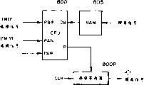
Figure 37 is the block diagram of an embodiment of the major part of expression liquid discharging device using it of the present invention.
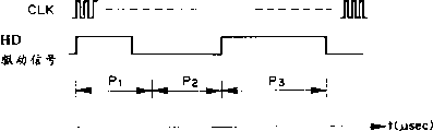
Figure 38 is the time diagram of each signal in the structure shown in Figure 37.
Figure 39 is the block diagram of expression according to another embodiment of the major part of the liquid discharging device using it of one embodiment of the present of invention.
Figure 40 is the time diagram of each signal in the structure shown in Figure 39.
Figure 41 is the flow chart that is used for the treatment step of structure shown in Figure 39.
Figure 42 represents the impulse waveform according to another example of the driving pulse of the jet head of one embodiment of the invention.
Figure 43 (a) shows hydrojet state when the impulse waveform among Figure 42 1 is provided for heater element, (b) shows the hydrojet state when the impulse waveform among Figure 42 1 ' is provided for heater element.
Figure 44 shows the spouting liquid of jet head in one embodiment of the invention with the relation between the time interval of driving pulse.
Figure 45 is the cutaway view according to the major part of the 1 type PWM control of one embodiment of the invention.
Figure 46 shows along the Temperature Distribution of the Z axle among Figure 45.
Figure 47 is illustrating according to the 1 type PWM control of one embodiment of the invention.
Figure 48 shows the viscosity of the liquid relation between synthermal.
Figure 49 shows spouting liquid with the relation between the surface tension of liquid.
Figure 50 is the cutaway view of the major part of the 2 type PWM control in expression one embodiment of the invention.
Figure 51 is the cutaway view of the major part of the 3 type PWM control in expression one embodiment of the invention.
Figure 52 shows the 3 type PWM control according to one embodiment of the invention.
Figure 53 is the cutaway view that is used to illustrate according to the jet head major part of the 4 type PWM control of one embodiment of the invention.
Figure 54 is the cutaway view that is used to illustrate by the another kind of jet head major part of the 4 type PWM control of one embodiment of the invention.
Figure 55 is illustrating of 4 type PWM control.
Figure 56 shows the result according to the 4 type PWM control of one embodiment of the invention.
Figure 57 is the perspective view that is used for the equipment of 4 type PWM control.
Figure 58 is the decomposition diagram according to ink gun in one embodiment of the invention.
Figure 59 compares with traditional jet head, the spouting liquid variation diagram when using the preheat pulse modulation of adopting dipulse according to the present invention.
Figure 60 and Figure 59 are similar, the variation of the spouting liquid of expression when modulating the time interval of dipulse.
Figure 61 schematically shows the waveform of dipulse.
Figure 62 is the block diagram that is used for carrying out according to the pulse width modulation of the preheat pulse of one embodiment of the invention the structure that trace revises.
Figure 63 is the detail circuits figure that circuit and drive circuit are selected in preheating among Figure 62.
In this spraying system, the raising that all is improved of the direction of propagation of the pressure that is used for hydrojet that produces by foaming by control and the direction of growth of bubble, jet power and efficient.
Fig. 1 is the simplified cross-sectional view of the jet head dissectd along one of this embodiment fluid course, and Fig. 2 is the stereogram that the partial cutaway of this jet head is gone.
The jet head of present embodiment has a heater element 2 (being in the present embodiment is the heating resistor of 40 μ m * 105 μ m) as spraying the energy generating device, is used for liquid supply heat energy to spray this liquid; Also have a device substrate 1, heater element 2 just is equipped with thereon; And fluid course 10 that is formed at the device substrate top corresponding to heater element 2 places.Fluid course 10 has fluid with a public fluid chamber 13 that liquid is supplied to this fluid course 10 and is communicated with, and path 10 is communicated with spout 18 fluids again.
Dispose a movable piece above the device substrate in fluid course 10 promptly by the metallic plate of making as the elastomeric material of metal one class that is the cantilever beam form 31, this plate is in the face of heater element 2.The basis that one end of movable piece is fixed on the wall that is disposed at device substrate or fluid course 10 that is made of photosensitive resin material is on the supporting member 34.By this structure, movable piece is supported, and constitutes a fulcrum (fulcrum part).
To introduce a basic ejector principle of the present invention at this.One of important principles of the present invention is, the movable piece of placing towards bubble is to produce according to bubble or the pressure of bubble own is shifted to the second place after being moved from normal primary importance, and movable piece 31 mobile or that be moved effectively will be by producing bubble and/or bubble itself pressure that the produced spout 18 (downstream) that leads of growing up.
To at length introduce the situation that traditional fluid course of not adopting movable piece (Fig. 3) and the present invention (Fig. 4) compare below.Use V here
ARepresent the direction of pressure, use V towards spout 18 transmission
BRepresent the direction of pressure towards the upstream side transmission.
In traditional jet head as shown in Figure 3, without any the structural detail that is used for regulating effectively the direction of transfer of the pressure of generation by generating bubble 40.Therefore, this pressure direction of transfer is perpendicular to the surface of this bubble like that shown in V1-V8, thereby their point to all directions of passage.In these directions, near the pressure direction of transfer (V1-V4) of half bubble of spout along direction V
AA pressure component is arranged, and this component is the most effective to spouting liquid.Because of it helps hydrojet efficient, hydrojet pressure and jet velocity, so this part component is very important.In addition, component V1 is near V
ADirection is an injection direction, thereby the most effective, and V4 is only at V
AA less component is arranged on the direction.
From another point of view, in situation of the present invention shown in Figure 4, movable piece 31 will steep lip-deep pressure direction of transfer V1-V4 (they are to transmit to all directions if it were not for movable piece is arranged) guiding downstream (being the spout side) effectively.So, the pressure direction of transfer of bubble 40 is concentrated, thereby makes the pressure of bubble 40 directly and effectively help to spray.
Be similar to pressure direction of transfer V1-V4, with the growing direction of the bubble downstream of leading itself, and in the growth in the downstream growth more than one side in the upstream.Like this, the growing direction of bubble itself is controlled by movable piece, thereby also just makes from steeping outside pressure propagation direction thus and be controlled, thereby ejection efficiency, jet power, speed or similar parameter are much improved and improve.
Return over and see Fig. 1, at length introduce the spraying of jet head in the present embodiment below.
(a) among Fig. 1 shows the state before will the energy as electric energy putting on heater element 2.Therefore, also there is not heat to generate.Should be noted that, movable piece 31 is so placed so that make it at least will be towards the downstream part of the bubble that is generated by the heat that heater element was produced, in other words, the trip partial action is on movable piece under the bubble in order to make, and the structure of fluid course should make movable piece extend to the downstream part (it is by heater element regional center 3 and perpendicular to trip place under the straight line of fluid course length direction) at the center 3 in heat generation part zone at least.
Fig. 1 (b) shows by heater element being applied electric energy and makes it to produce state when hot, at this moment is filled in a part of liquid in the foaming district by the heat that is generated heating, thereby makes it to produce a bubble by film boiling.
At this moment, movable piece 31 is shifted to the second place by the pressure that the generation owing to bubble 40 produces from primary importance, so that with pressure transmission guiding spout.Should be noted that, as mentioned above, the free end 32 of movable piece 31 places downstream (being spout one side), and fulcrum 33 then is placed in upstream side (being public fluid chamber side), thereby make part roam all around the would under the bubble of movable piece at least, promptly towards the downstream part of heater element.
Fig. 1 (c) shows bubble 40 states of further growing up.Under by the effect that produces pressure due to the bubble 40, movable piece 31 is moved further.Bubble is greater than growth along updrift side along the growth of downstream direction, and bubble extends to outside the primary importance (dotted line position) that substantially exceeds movable piece.Be appreciated that like this along with bubble 40 increase, movable piece 31 progressively moves, thus, pressure direction of transfer, the volume of bubble 40 move the direction that (expanding) carries out easily, that is the growing direction of bubble is by the spout that leads uniformly, thereby ejection efficiency is improved.When movable piece will steep and steep generation pressure guiding spout, it can not stop propagated and growth, and can control the growing direction and the pressure propagation direction of bubble according to the size of pressure effectively.
Fig. 1 (d) shows owing to steep the attenuating of internal pressure after the film boiling, the state of bubble 40 contractions and disappearance.
Under effect, simultaneously also because under the effect of the negative pressure that the bubble contraction produces, the movable piece 31 that has been moved to the second place returns its home position, i.e. primary importance shown in Fig. 2 (a) by the restoring force that elasticity provided of movable piece itself.Because the disappearance of bubble, liquid are flowed from by V
D1And V
D2Shown in public fluid chamber side and from by the spout side reflux shown in the Vc, reducing and compensate the injected liquid of walking with the bubble of compensation in foaming district 11.
In front, the spraying of the generation of concrement vacuole and liquid has been introduced the function situation of movable piece 31.To be presented in the situation that recharges of liquid in the jet head of the present invention now.
Referring again to Fig. 1, introduce liquid supplying device below.
When bubble 40 entered in its arrival maximum volume (shown in Fig. 1 (c)) bubble contraction process afterwards, a part was enough to the liquid of compensate for shrinkage foam volume from spout 18 sides of first fluid course 14 and the public fluid chamber 13 side inflows foaming district of second fluid course 16.Under the situation of the liquid flowing channel structure of traditional no movable piece 31, from the amount of liquid of spout side inflow bubble shrinking zone with from the amount of liquid of public fluid chamber inflows, corresponding to from the liquid resistance (inertia of fluid course resistance and liquid) of spout than this part of the liquid flowing resistance of this part near and close public fluid chamber from the foaming district.
Therefore, when at the liquid flowing resistance of supply oral-lateral during less than other side, a relatively large liquid is from spout side inflow bubble disappearance position, and its result causes meniscus to shrink increasing.Reduce the liquid flowing resistance at the spout place in order to increase ejection efficiency, the contraction of meniscus M increases along with the disappearance of bubble, and it is elongated that the result causes recharging the time cycle, thereby be difficult to carry out flying print.
Concerning present embodiment, owing to be provided with movable piece 31, when movable piece was got back to its original position along with the disappearance of bubble, the contraction of meniscus just stopped at this moment, after this, filled the liquid of a volume W2 and supplied with by the liquid stream V by second fluid course 16
D2Finish (W1 is that the foam that surpasses the primary importance of movable piece 31 amasss Side Volume on the W, and W2 is the volume of the long-pending W of foam in foamed zones 11).In the prior art, half of the long-pending W of foam is the volume that meniscus shrinks, but in the present embodiment, the volume of only have an appointment half (W1) is the volume that meniscus shrinks.
Therefore, force the liquid supply that is used for volume W2, along the surface of the heater element side of movable piece 31, from the upstream (V of second fluid course mainly by utilizing the pressure that disappears and produce by bubble
D2) realize, thereby can realize recharging more efficiently.
When utilizing the pressure that is produced by the bubble disappearance to recharge in traditional jet head, the vibration of meniscus is extended, and the result degenerates picture quality.But in the present embodiment, the liquid stream in the first passage 14 of the spout side in spout side and foamed zones territory 11 is suppressed, thereby the vibration of meniscus is reduced.
So, with regard to present embodiment, forcibly foamed zones is recharged and realize refilling at a high speed by suppressing meniscus contraction and vibration by liquid feeding channel 12 from second channel 16.Therefore, can realize stable the injection and injection repeatedly at a high speed, thereby when present embodiment is applied in the record field, can improve picture quality and writing speed.
Present embodiment provides following effective efficiency.It is a kind of inhibition to the pressure side transmission upstream (echo) that produced by foaming.Because the public fluid chamber 13 of foaming one side (upstream side) on heater element 2, pressure are changed into a kind of power that liquid is returned toward the upstream thruster (fluctuation back) mostly.Resultant motion and synthetic inertia force that this fluctuation back hinders by upstream side pressure, liquid recharge into this fluid course liquid.In the present embodiment, these effects to upstream side are suppressed by movable piece 31, thereby have further improved the ability of recharging.
To introduce other feature and good effect below.
Can pass through foamed zones territory supply liquid as V
D1Shown in carry out in a gap of movable piece sidepiece (narrow slit 35) like that.For the spout that more effectively will lead by the pressure that foaming is produced, can adopt a big movable piece that covers whole foaming district (covering the surface of heater element), its situation is as shown in Figure 1.Like this, the liquid flowing resistance for distinguishing the liquid between 11 at first fluid course 14 near the zone and the foaming of spout owing to movable piece recovers to increase to its primary importance, thereby can suppress along V
D1Liquid stream to foaming district 11.But, concerning this jet head of present embodiment, there is a liquid stream effectively liquid to be supplied to the foaming district, the liquid deliverability is increased greatly.Thereby, even movable piece 31 covers the foaming district to improve ejection efficiency, can not make liquid deliverability variation yet.
The free end 32 of movable piece 31 is such with the correlation of fulcrum 33: for example as shown in Figure 5, free end 32 is in the downstream position of fulcrum.Utilize this structure, can guarantee function and effect effectively according to the generation of bubble with the growing direction of pressure direction of transfer and bubble guiding spout side, therefore, this position relation is not only effective to realizing relevant effect, function of spraying, and effective by the liquid flowing resistance of fluid course 10 when reducing supply liquid, thereby can allow to carry out refilling at a high speed.When the meniscus by as shown in Figure 5 injection reduction returns spout 18 by capillary force, or when implementing the disappearance of supply compensating liquid bubble, free end 32 and fulcrum 33 positions of living in make liquid stream S1, the S2, the S3 that pass the fluid course 10 that comprises first and second fluid course 14,16 not interrupted.
More particularly, as previously mentioned, in the present embodiment, the downstream position at the free end 32 facing area centers 3 of movable piece 31, the center 3 in zone is divided into heater element 2 upstream side and downstream area (passing the core in heater element zone and the straight line vertical with the length direction of fluid course) in heater element zone.Movable piece 31 bears pressure and bubble (they are in the downstream at the center 3 in heater element zone, and injection has big help to liquid), and movable piece 31 has so just improved ejection efficiency or jet power widely with these power guiding spout sides.
As previously mentioned, utilize the upstream of bubble that other good result also is provided.
Therefore can think, in this structure of present embodiment, the mobile hydrojet that helps of free-ended moment machinery of movable piece 31.
<embodiment 2 〉
Fig. 6 shows second embodiment: in Fig. 6, though bubble is not shown, A represents the movable piece that is moved, and B is illustrated in the movable piece (primary importance) in home position, on this position bubble generation area 11 basically relatively spout 18 be sealed.Though not expression has a fluid course wall with this fluid course separately between A, B.
Set a pedestal 34 on each limit, between pedestal, form liquid feeding channel 12.With this structure, liquid can be from have roughly the liquid feeding channel with the surperficial concordant of heater element or the surface passed through continuously smoothly between them, along a surface supply towards heater element of movable piece.
When movable piece 31 is in its home position (primary importance), movable piece 31 near or closely contact place a downstream wall 36 in heater element 12 downstreams and be placed in the heater element sidewalls 37 at these places, side of heater element, be sealed basically thereby make foaming distinguish 11 spout side.Like this, when forming, bubble, especially can be concentrated on the free end side of movable piece at the pressure that steeps the downstream by the pressure of bubble generations, and release pressure not.
In the process that bubble disappears, movable piece 31 returns its primary importance, thereby the spout side in foaming district 11 is closed basically, thereby has suppressed the meniscus contraction, in mode with above-mentioned advantage to the heater element feed fluid.About recharging, the same in the foregoing description that coexists, also can provide identical good result.
In the present embodiment, pedestal 34 is used for supporting promptly fixedly movable piece 31, and pedestal 34 is configured in the upstream side away from heater element 2, and its situation such as Fig. 2 are shown in Figure 6, and the width of pedestal 34 is less than fluid course 10, so that liquid is supplied to liquid feeding channel.The shape of pedestal 34 is not only limited to illustrated this structure, can be used as long as can finish any structure that recharges reposefully.
In the present embodiment, the gap between movable piece 31 and the heater element 2 approximately is 15 μ m, if the pressure that is produced by bubble can be transferred into movable piece satisfactorily, also can adopt crack between the different sizes.
Fig. 7 has showed a basic sides of the present invention.Fig. 7 shows the mutual alignment relation between foaming district, bubble and the movable piece in a fluid course, in order to liquid discharging method and the re-fill method of further introduction according to one aspect of the invention.
In the above-described embodiments, the pressure that is produced by the bubble that generates is concentrated on the free end of movable piece, so that finish mobile spout one side that concentrates on that moves and make bubble rapidly of movable piece.In the present embodiment, bubble is freely relatively, is in spout one side, directly helps the downstream part of the bubble of drop injection to be regulated by the free end side of movable piece.
More particularly, do not set the teat of its effect in the present embodiment as the supporting of one on the heater element substrate 1 in Fig. 2.The free end portion of movable piece and relative relative spout district, side district do not have basic seal foaming district, but in the present embodiment, movable piece will foam to distinguish to the spout district and open wide.
In the present embodiment, the growth that permission is steeped on the leading end part of the downstream of the downstream part with guiding drop ejection function, therefore, pressure component is used in injection effectively.In addition, in this downstream part towards upward pressure (component V
B2, V
B3And V
B4) effect like this, make the free end side of movable piece partly help the increase of the bubble on this guide end part with activation.Therefore, the same with aforementioned each embodiment, ejection efficiency is improved.Compare with those embodiment, present embodiment is better on the response that heater element is driven.
Therefore present embodiment simple in structure be easy to make.
The fulcrum of the movable piece 31 of present embodiment partly is fixed on the pedestal 34 that its width is narrower than the movable piece surface.Liquid supply along with the disappearance of bubble to foaming district 11 is carried out along the two sides (being represented by arrow) of this pedestal.As long as supplying functional is guaranteed that pedestal also can be other form.
In the present embodiment, being provided with of movable piece helps control enters foamed zones from top along with the disappearance of bubble liquid stream.It is better than the tradition bubble generation structure that only has heater element to be used for refilling of feed flow.The contraction of meniscus also is suppressed therefrom.
In a preferred variant embodiment of this 3rd remodeling, these two horizontal sides (or having only a horizontal side) sealed up substantially for foaming district 11.Because this structure, the pressure towards the horizontal side of movable piece also is directed to the spout side end, thereby has further improved ejection efficiency.
Among the embodiment below, move and the jet power that is used for liquid that produces is further improved by machinery.Fig. 8 is a cutaway view of present embodiment.In Fig. 8, movable piece is extended to such an extent that make the free end position of movable piece 31 more be in the downstream part of heater element.Because be provided with like this, movable piece is further strengthened in the translational speed of its free end, thereby the expulsion pressure that produces that moves by movable piece is further improved.
In addition, this free end is than the more close spout side of the foregoing description, thereby the increase of bubble can more be concentrated on the direction that is stabilized towards it, thereby guarantees better injection.
In response to the growth rate of bubble at bubble pressure central portion branch, movable piece moves with a translational speed R1, and the free end that is in than the more close nozzle exit area of the movable piece of this position place moves with higher speed R2.Like this, free end 32 mechanically acts on liquid and has increased ejection efficiency with higher speed.
As shown in Figure 7 the same of free end shape, its edge-perpendicular flows in liquid, and thus, the pressure of bubble and the mechanism of movable piece more effectively help injection.
Fig. 9 (a) and (b) and the 5th embodiment that (c) shows according to injection method of the present invention.
As with the foregoing description difference, be not communicated with the zone that spout directly is communicated with public fluid chamber side, structure is simplified.
Just 31 foaming district side is supplied to liquid from liquid feeding channel 12 along movable piece.The position relation of the free end of movable piece 31, fulcrum 33 relative spouts 18 and all similar to the aforementioned embodiment towards the structure of heater element 2.
Concerning present embodiment, good result is all arranged in the above in ejection efficiency, feed flow function and described each side.And, the contraction of meniscus is suppressed, and the mandatory pressure that recharges when fully utilizing bubble to disappear is basically realized.
Fig. 9 (a) shows the state that is made the bubble generation by heater element, the state when Fig. 9 (b) then shows bubble and shrinking.At this moment, movable piece 31 returns its reset condition, and the liquid supply is realized by S3.
In Fig. 9 (c), shrink M and recharge compensation by what capillary force caused closing on spout 18 places owing to movable piece returns little meniscus that its reset condition has.
Introduce another embodiment below.
Hydrojet principle in the present embodiment is same as the previously described embodiments.Its fluid course is a multi-channel structure, and the liquid that is used for producing bubble by heating is separated with injected usually liquid.
Figure 10 is the simplified cross-sectional view of dissecing along the fluid course direction of the jet head of present embodiment.
In the jet head of present embodiment, second fluid course 16 that is used for generating bubble is configured in device substrate 1, device substrate 1 is provided with one and is used for providing heat energy to produce the heater element 2 of bubble at liquid, is used to 14 tops that are formed at fluid course 16 of first fluid course that cause liquid to be communicated with spout 18.
The upstream side of first fluid course 14 is communicated with first public fluid chamber 15 fluids, be used for atomizing of liquids is infeeded one group of first fluid course, the upstream side of second fluid course is communicated with the second public fluid chamber fluid, is used for expanding foam solution is supplied to one group of second fluid course.
At expanding foam solution and jetting fluid is under the situation of same liquid, and public fluid chamber can be one.
Between first and second fluid course, the partition wall 30 that useful elastomeric material as metal is made, thus first and second fluid course is separated out.Should be under the situation of minimum degree at expanding foam solution with mixing of jetting fluid, and first and second fluid course 14,16 the most handy these dividing walls separate.But mixing to a certain extent is when can allow, and it is unnecessary separating completely.
Dividing wall is the movable piece 31 that is cantilevered fashion in the part that projects upwards in the space of heater element, it is formed by long and narrow slit 35, one fulcrum 33 is arranged and in spout 12 sides (total relatively liquid stream is downstream part) free end is arranged in public fluid chamber (15,17) side.Expulsion pressure produces the district and comprise A and B (foaming district 11) in Figure 10.Make movable piece 31 towards its surface, so movable piece can be operated when expanding foam solution foams the spout side to first fluid course and opening (along direction shown in the arrow in this figure).In the example of Figure 11, also place a dividing wall 30 on device substrate 1.Device substrate 1 disposes 5, one spaces of link electrode that the heating resistor as heater element 2 partly reaches in order to heating resistor is partly provided electric signal and is used to constitute second fluid course.
Among correlation between the fulcrum 33 of movable piece 31 and free end 32 and the heater element and the previous embodiment is the same.
In the example formerly, by the agency of the relation between the structure of liquid feeding channel 12 and heater element 2.In the present embodiment, second fluid course 16 also is the same with relation between the heater element 2.
Referring to Figure 12, the operation of the jet head of present embodiment will be introduced.
In first fluid course 14 by with the jetting fluid of crossing and in second fluid course 16 by with expanding foam solution all are water-based inks.
By the heat that is produced by heater element 2, the expanding foam solution in the foaming district of second fluid course produces a bubble by foregoing film boiling phenomenon.
In the present embodiment, except the upstream side in the foaming district, bubble generates pressure and is not released on remaining three direction, so that make this pressure of producing by foaming be passed to moving element side in expulsion pressure produces part by the concentrated area, make therefrom this movable piece from the position shown in Figure 12 (a) along with the increase of steeping is moved toward the first fluid course side shown in Figure 12 (b).By this action of movable piece, first and second fluid course 14,16 is linked up with free from worry fluid connection method each other, and is mainly passed to the spout in the first fluid course side (direction A) by the pressure that foaming produces.Move by this transmission of pressure and this mechanical displacement of movable piece, liquid is sprayed from spout.
Afterwards, along with the contraction of bubble, movable piece turns back to the position shown in Figure 12 (a), thereby from the supplied upstream of first fluid course 14 amount of fluid corresponding to injected liquid.In the present embodiment, the feed flow direction as above-mentioned those embodiment be with the closing direction of movable piece in the same way, liquid recharge the obstruction that can not be subjected to movable piece.
In the present embodiment, the same about along with among the major function that the aspect such as prevents of the transmission of the pressure that is produced by foaming that moves of movable wall, direction that bubble increases and fluctuation back and effect effect and first embodiment, still two liquid flowing channel structures have advantage on following each point.
Can separate jetting fluid and expanding foam solution, the pressure injection that jetting fluid is produced in expanding foam solution.Thereby when a kind of high viscosity liquid as polyethylene glycol or analog was used as expanding foam solution, because do not have enough jet powers by heating, former Ceng Buneng sprayed it with good state, and present this high viscosity liquid can be injected.For example this liquid can be supplied to first fluid course, and (in addition) a kind of liquid is because of the good state that foamed with it, thereby it is fed in second fluid course is used as expanding foam solution.A kind of example of foaming liquid is the mixing material (about 1-2cp centipoise) of a kind of anol (anol) and water (4: 6).Thus, spray liquid suitably just.
In addition, by selecting a kind of liquid,, make foaming stable, thereby guarantee correct injection even when heating, adopt this liquid also not have attachment and stay on the surface of hot producing component as expanding foam solution.Each action effect of having introduced among each embodiment provides in the present embodiment too in front, can spray high viscosity liquid or analog with high ejection efficiency and high injection pressure.
In addition, can spray heat labile liquid.In this case, this liquid is conducted to first fluid course as jetting fluid, and its character is difficult for infeeding second fluid course for heat changes and can be used to the good a kind of liquid that foams.Like this, can be with the ejection of this liquid and unlikelyly be subjected to pyrolytic damage, and high ejection efficiency and high injection pressure are arranged.
In the superincumbent narration, the major part of injection method of the present invention and jet head is introduced.Below the more detailed embodiment that can be used for the various embodiments described above is described.Following embodiment need not special declaration applicable to two types of single, double fluid courses.
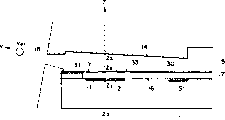
Figure 33 has described the pulse of using in this example that is decomposed.
Among Figure 33, Vop represents driving voltage; P
1The pulse width of first pulse (preheating pulse) of the heating pulse (driving pulse) that expression is decomposed; P
2The pulse width of representing blanking time; P
3Represent second pulse (main heating pulse).T
1, T
2And T
3Be decision pulse width P
1, P
2And P
3Time.Driving voltage Vop produces a numerical value in the 40 necessary electric energy scopes of bubble by the heater element 2 as the electrothermal transducer of supplying with this voltage in printing ink, it depends on the area of heater element 2, resistance, membrane structure, and/or the liquid flowing channel structure of record head.In the modulator approach of the pulse width that is decomposed, it is P that width is provided
1, P
2And P
3Train pulse.In the present embodiment, the ink temperature in the preheat pulse major control fluid course, and be used for controlling spouting liquid.The pulse width P of preheat pulse
1Be such, that is, and when it does the time spent, by heat energy generation foaming in of heater element 2 generations as the printing ink of jetting fluid.
Blanking time P
2Be the interference that is used for avoiding between preheat pulse and main heating pulse, and the ink temperature in the printing ink fluid course is evenly distributed.Main heating pulse produces a bubble in the printing ink of fluid course, to pass through spout 18 ink jets, its width P
3The area that depends on heater element 2, resistance and/or membrane structure, and/or the structure of the printing ink fluid course of record head.
Figure 34 is the chart of expression ink ejection amount with respect to the functional relation of preheat pulse, wherein V
0Be P
1Spouting liquid during=0 (μ second), its value depends on the structure of jet head.In this example, V
0=18.0ng/dot.
Shown in curve among Figure 34, along with the pulse width P of preheat pulse
1From P
1Be increased to P
ILMT, emitted dose Vd increases linearly.
In such scope, promptly with respect to pulse width P
1Variation, spouting liquid V
dBe linear change, just, arrive P
ILMTScope in, by changing pulse width P
1, can easily control emitted dose.In this example, can see, work as P by curve a
ILMTDuring=1.87 (μ s), spouting liquid V
LMT=24.0ng/dot.As spouting liquid V
dWhen maximum, pulse width P
IMAX=2.1 μ s, spouting liquid V
MAX=25.5ng/dot.
Pulse width P when preheat pulse
1Greater than P
1MAXThe time, spouting liquid V
dLess than V
MAXThis be because, when the pulse width of the preheat pulse that provides is in this scope, on heater element 2, produce small bubble (the just state before film boiling), and in microvesicle disappearance prerequisite for main heating pulse, cause the generate heat foaming of pulse of microbubble destruction master to produce, thereby spouting liquid is reduced.This scope is called as the prefoam zone, and wherein, it is difficult using preheat pulse control spouting liquid.
In emitted dose and at scope P
1=0-P
ILMTOIn the functional relation coordinate diagram of the pulse width in (μ s), the gradient of straight line is the coefficient that preheats impulse function, that is:
K
p=ΔV
dp/ΔP
1ng/μsec·dot
COEFFICIENT K
pTemperature independent, depend on the structure of jet head, drive condition, ink property etc.In other words, the record head that curve b, c representative is other if record head is different, is appreciated that so it also is different.Like this, different record heads has the different pulse width P that preheats pulse
1Upper limit P
ILMTTherefore, as described below, determine the upper limit of each record head, to realize the control of spouting liquid.In the printing ink and record head that have by the represented character of curve a, K
p=3.209ng/ μ secdot
Another factor of the spouting liquid of decision ink jet print head is the temperature (ink temperature) of record head.
Figure 35 shows the relation curve of spouting liquid and temperature.From the curve a of Figure 35 as can be seen, spouting liquid V
dAmbient temperature T with record head
R(=record head temperature T
H) increase and linear increasing.When the gradient of this line is defined as the coefficient correlation of temperature, there is following formula:
K
T=ΔV
dT/ΔT
H(ng/℃·dot)
COEFFICIENT K
TDo not rely on drive condition, and by the structure of record head, decisions such as ink property.Among Figure 35, curve b, c show the characteristic of other record head.In this routine record head, K
T=0.3/ ℃ of dot.
Therefore, the PWM (pulse width modulation) of the pulse width by preheat pulse control can be controlled ink ejection amount reliably, thereby can improve the gradation of printing, and can make ink ejection amount stable.
For example, preheat pulse makes the shortage of heat of heater element 2 generations with hydrojet, and improves the operating condition of movable piece 31, thereby makes the spouting liquid and the hydrojet velocity-stabilization of liquid.More particularly, the liquid in the foamed zones 11 is by the preheat pulse preheating, so that viscosity is reduced, in this case, the transmission efficiency that passes to the pressure of movable piece 31 is high.Therefore, when main heating pulse is provided, reliably and effectively carry out the initial motion of movable piece 31, cause the reliability of movable piece 31 to improve, thereby improve the injection conditions of liquid.Because the improvement of the spray regime of liquid only depends on the injection of liquid, therefore, even when continuous injection liquid, also can provide desired spray regime (when by the ink jet printing image, spray regime is used for guaranteeing the gradation of image) really.
On the basis of the mensuration temperature that is provided by the temperature sensor as the diode on being arranged on record head, the pulse width of preheat pulse can be controlled by PWM.In this case, preferably consider determined temperature with the temperature contrast that the position relation of 2 of heater elements causes according to driven spout 18 with by temperature sensor.Use the material of the material of metal and high thermal conductivity, can realize the preheating of jetting fluid effectively as movable piece 31.In addition, movable piece 31 can absorb from the heat near the liquid of heater element 2, and this liquid is by preheat pulse or owing to continuous injection liquid or similar behavior are heated.Therefore, it is uniform can making the heat of the liquid of close heater element 2, thereby the temperature that can make heater element 2 is with being minimized by the difference between the detected temperatures that is located at the temperature sensor measurement on the record head, like this, has improved the precision of PWM control preheat pulse.
Set forth the object lesson that driving pulse is provided to heater element 2 below.
Used nozzle arrangements shown in Figure 36 (a), as Figure 36 (a) with (b), pulse width t
1, t
2, t
3Select as follows:
1μsec≤t
1≤1.4μsec
1.5μsec≤t
2≤3μsec
3 μ sec≤t
3≤ 8 μ sec (best, 5 μ sec≤t
3≤ 8 μ sec)
Utilize these conditions, suitably control spouting liquid, when using the ink printing image, can finish multi-level gradation control according to the shape of driving pulse.
Slightly be longer than 1.5 μ sec≤t when making preheat pulse
1≤ 1.8 μ sec when making the temperature of the liquid of contiguous heater element 2 be elevated to a certain degree thus, have finished the control of the spouting liquid in being lower than about 10ng scope of this liquid.When the printing ink as jetting fluid is directed onto on the transparent or semitransparent OHP paper, and when printing, in most cases can obtain the high density printing, thereon although the correction of the variation of spouting liquid also is very important.Therefore, when on OHIP paper, printing, can not realize pulse width P according to the PWM of record head temperature control
3Fix.In this case, make pulse width P
1Long as much as possible, with the increase spouting liquid, thereby improve density.
Figure 37 is the block diagram of the driving control of the expression record head that is used for OHP paper, and Figure 38 is the time diagram of each signal.The pattern of waveform that is used for the driving signal of record head has pre-deposited ROM803.At first, at the output time of the driving signal that is used for record head, a clock pulses signal is offered the counter 800C of the controller of tape deck.Every input clock pulse signals, the output of counter just increases by 1.Like this, the internal memory of ROM803 is exported according to the address of the output of counter, and drives signal as record head.
According to the pulse width P that has the preheat pulse that is used for each temperature
1The selection of PWM control panel export record head and drive signal.As shown in figure 38, record head driving signal is exported according to selected figure.This record head drives the selection of signal graph, depends on the PWM control panel selection signal that offers ROM 803.When OHP paper selects signal to adopt the H level, by or the effect of door 800A, all offer the PWM plate of ROM 803 and select input signals of signal to adopt the H level, therefore, no matter how the PWM plate selects signal, has selected figure AN+ α-1, makes the pulse width P of the preheat pulse of representing at Figure 38 top like this
1Be fixed on maximum.Specifically, work as P
1During=2.618 μ sec, P
3=4.114 μ sec.
Record head when Figure 38 represents that the printing ON signal when printing is H drives signal.When printing ON signal was L (not printing), the record head that Figure 38 represents drove the pulse P of signal
3Adopt the L level.
In the present embodiment, the pulse width P that only works as preheat pulse
1When being fixed on maximum, could realize the increase of spouting liquid.With respect to normal temperature, improve the predetermined temperature of record head, can further improve emitted dose.Specifically, predetermined temperature is brought up to 40 ℃ from normal 25 ℃.If make temperature be higher than 40 ℃, because temperature has improved about 15 ℃, the temperature of record head will be closed on the limiting temperature T of record head
LIMIT=60 ℃, therefore, this rising is bad.
When measuring the OHP pattern by the kind of measuring used paper, driving control becomes possibility.
Referring to Figure 39 to Figure 41, another example that record head drives control will be described below.Figure 40 is the time diagram of each signal in the structure shown in Figure 39.
In Figure 39, picture signal is deposited in RAM 805 as printed data.When depositing picture signal in RAM 805, CPU 800 inserts view data among the shift register 800R, produces record head and drives signal.Flow chart below in conjunction with Figure 41 describes in detail.
See Figure 41, in step S1, CPU800 reads the view data from the pixel of RAM 805, and runs to step S2.At step S2, whether the data of judging a pixel need to print, that is, and whether ink-jet.If the result who judges is sure, run to step S
3,, enter step S9 if negate.
At step S3, the register 12 of CPU 800 is remembered main pulse width P
3The level in stage is H, and continues to run until step S4.At step S4, read in PWM and select signal, and with the pulse width P of H level
1Deposit the register 12 of CPU 800 in, and operation enters step S5.At step S5, read in OHP and select signal, if selected the OHP pattern, then run to step S6, if do not select, run to step S7.
At step S6, will be by the width P of the H level of the preheat pulse of step S4 decision
1Be set to the Breadth Maximum that can be provided with, and deposit in the register of CPU 800, run to step S7 then.At step S7, according to the pulse width P of the preheat pulse that is stored in the register that is used for CPU 800 among Figure 40
1Pulse width P with main pulse
3Information, produce record head and drive signal.Then, run to step S8.The record head driving signal and the clock pulses that deposit shift register 800R in are synchronously exported from shift register 800R.
At step S8, whether all images data that deposit RAM 805 in exported judge, if sure, process is finished, if negate, then step S1 is got back in operation.
Figure 42 is illustrated in the oscillogram of selectable driving pulse in the above-mentioned RWM control.
When using common printed paper rather than having the OHP paper of light transmission part, select to be used for PWM control by the waveform shown in 1~11 among Figure 42 according to temperature of measuring or similarity.
Among the embodiment in front, when at the enterprising line item of OHP paper, only be to can be used for control by 1 pulse of indicating among Figure 42.
In 1~11 the PWM control in adopting Figure 42, P
1And P
2Variable respectively, can control spouting liquid thus.But, by changing P at interval
2Width, can control spouting liquid.In this case, shown in 1 ' among Figure 42,, will send foamed zones 11 or movable piece 31 fully to, thereby increase the size of bubble, improve spouting liquid owing to the heat that preheating produces by increasing at interval.
According to the PWM control of 1~11 among Figure 42 and 1 ' expression,,, make growth rate by the spouting liquid of PWM control than there not being the raising under the conventional situation of movable piece with the bubble guiding mouth spray that expands by movable piece 31 is provided.
Figure 43 is illustrated among each embodiment of the present invention, and the impulse waveform that offers heater element 2 is with the relation between the hydrojet state.This figure corresponding diagram 1 (c), and given similar reference numerals.The hydrojet state of Figure 43 (a) expression when the impulse waveform among Figure 42 1 is offered heater element 2, the hydrojet state of Figure 43 (b) expression when the impulse waveform among Figure 42 1 ' is offered heater element 2.In Figure 43 (a), bubble 40 is grown towards spout effectively.Because the abundant transmission of heat, such when big shown in Figure 43 (b) when the size of bubble 40, the displacement of movable piece 31 increases, thereby bubble 40 increases to the growths of spout direction, causes spouting liquid to increase.This is because make movable piece deflection, makes bubble towards spout, causes steeping 40 motion and growth towards spout, and is little on the direction of the elastic stress of resistance movable piece 31 along the resistance ratios of this direction.Therefore, compare, use the interval P between movable piece 31 and control preheat pulse and the main pulse with the traditional jet head that does not have movable piece 31
2Width can make the non-linear increase of rate of change of spouting liquid, rather than traditional linearity increases, but causes the control ability of spouting liquid to improve.Width P by the control preheat pulse
1, the rate of change of spouting liquid is raise, thereby but also can improve the control ability of spouting liquid.(according to the 1 type PWM control of the state parameter of liquid):
In the present invention, " state parameter of liquid " comprises the physical parameter that influences spouting liquid, as temperature, and the viscosity of liquid, the surface tension of liquid.When liquid is printing ink, comprise the character of printing ink.As described below, PWM control can be dependent on the kind of printing ink.As control interval P
2The result the spouting liquid rate of change increase and have the character of nonlinear area, the control ability of gradation is improved.In this example, the temperature T 2 of liquid (expanding foam solution) is by the temperature sensor measurement in element basic unit 1 in second fluid course 16, and the temperature T 1 of the liquid in first fluid course 14 (record use liquid) is predicted on the basis of mensuration temperature T 2.The pulse width P of preheat pulse among Figure 33
1According to predicted temperature T1, mensuration temperature T
2And the difference between them is controlled by PWM.Preferably consider the viscosity ρ of the record of temperature influence with liquid
1With its surface tension η
1
Figure 46 represents among Figure 45 the Temperature Distribution along Z-direction.In Figure 46, ignore with the Temperature Distribution in the liquid at element basic unit 1, expanding foam solution and record.In the figure, the mensuration temperature of temperature sensor S1 is considered to the temperature T of element basic unit 1
3, the temperature T of expanding foam solution
2With the temperature T of record with liquid
1By measuring temperature T
3Prediction (T
3〉=T
2〉=T
1).
Figure 47 represents an example, wherein the pulse width P of preheat pulse
1Be progressively controlled, thereby keep control width ± Δ V of a constant spouting liquid Vd.In this example, the record temperature T of liquid
1, the temperature T of expanding foam solution
2Perhaps the difference between them is as fluid temperature T
H, as fluid temperature T
HAt T
0And T
LBetween the time, according to fluid temperature T
HA chart among the option table 1-11 progressively changes the pulse width of preheat pulse whereby.In chart 1-11, the pulse width P of preheat pulse
1Press among Figure 42 1~10 small gradient setting.For example, design temperature T
0Be 25 ℃, when temperature was lower than this temperature, the temperature adjustment of record head was carried out for 25 ℃ by predetermined temperature.Fluid temperature T
HScope be T
LPerhaps higher, exceeded normal print range, therefore, such scope is without commonly used.Yet when record head moved with 100% load, temperature can enter this scope.In this zone, work as P
1During=0 (micro sec), only under the pulse condition of main heating pulse, print, thereby temperature own is increased to minimum.If necessary, can adopt the PWM control of pulse to raise to suppress temperature.The validity limit temperature of record head is specified by TC.
Relation between Figure 48 express liquid temperature and the liquid viscosity, wherein ρ
A(T
A) and ρ
B(T
A) be respectively in temperature T
AThe time, low relatively viscosity ρ
ALiquid and viscosity higher ρ
BThe viscosity of liquid is in temperature T
B(>T
A) viscosity be respectively ρ
A(T
B) and ρ
B(T
B).
The effect of surface tension spouting liquid of liquid, for example, surface tension with the relation between the spouting liquid as shown in figure 49.Figure 49 relates to this situation, wherein, and under identical condition, have little capillary liquid A, as the infiltrative printing ink of superelevation, its spouting liquid increases, and have big capillary liquid B, as be used for improving the processing hydrojet of picture quality in the ink-jet front and back, its spouting liquid reduces.
The employing temperature T is described below
1, T
2The object lesson of PWM control.In PWM control, can control the pulse width P of preheat pulse
1, time interval P
2Pulse width P with main heating pulse
3In one, perhaps they are jointly controlled.That describe below is the pulse width P of control preheat pulse
1Situation.
1) T
1=T
2Situation
A) record is identical printing ink with liquid A and expanding foam solution B
The state parameter of liquid A and B is identical, i.e. φ A (ρ
1, η
1)=φ B (ρ
2, η
2), therefore, according to temperature T
2(=T
1) control preheat pulse pulse width P
1Thereby, only control the volume of the foaming of expanding foam solution B.
B) record is different printing ink with liquid A and expanding foam solution B
For example, (ρ when liquid A, B have different viscosity
1<ρ
2), their state parameter is different, i.e. φ A (ρ
1, η
1) ≠ φ B (ρ
2, η
2).After long-time resting stage, perhaps after record head having been carried out sufficient temperature control, when starting printing operation this situation can appear.Even the temperature of liquid A, B is identical, the record viscosity ρ of liquid
1Also greater than the viscosity ρ of expanding foam solution
2, therefore, if according to temperature T
2(=T
1) control preheat pulse pulse width P
1Thereby can only control the volume of the foaming of expanding foam solution B as a), so, because expulsion pressure reduces, the blow pressure of expanding foam solution B is delivered to record liquid A.Therefore, do not provide the spouting liquid Vd of expection, thereby printing density is reduced.So, correspondingly, make the pulse width P of preheat pulse
1Be provided with than the length in a) situation, to avoid reducing of spouting liquid.
2) T
1<T
2Situation
C) record is identical printing ink with liquid A and expanding foam solution B
Usually, because printing operation raises the temperature of record head, the temperature of expanding foam solution B is than the temperature height of record with liquid A.Therefore, above-mentioned state occurs during normal printing operation.The viscosity ρ of liquid A, B
1, ρ
2Depend on temperature T
1, T
2, therefore, state parameter is different, i.e. the record viscosity ρ of liquid A
1Viscosity ρ than expanding foam solution B
2High.Same b) situation is the same, because the blow pressure of expanding foam solution B passes to record liquid A, expulsion pressure reduces, thereby can not guarantee the spouting liquid Vd that expects, makes the printing density reduction.So, correspondingly, make the pulse width P of preheat pulse
1Be provided with than the length in a) situation, to avoid reducing of spouting liquid.
It would be desirable temperature T
1And T
2Between difference DELTA T determine, can measure by experiment corresponding to the difference of the spouting liquid of Δ T, and can obtain to be used for the pulse width P of PWM control
1
P
1=P
1(0)+ΔP(T)+ΔP(ΔT)
Wherein, P
1(0) expression reference pulse width; Δ P (T) is the temperature correction, and it is a temperature T
1Or T
2Function; Δ P (Δ T) is the emitted dose difference corresponding to temperature gap Δ T.For example, P
1(0)=2.0 (μ sec), Δ P (T)=0-2.0 (μ sec), Δ P (Δ T)=0-1.0 (μ sec).
D) record is different printing ink with liquid A and expanding foam solution B:
When at the enterprising line item of common paper, record may be to have utmost point low surface tension η with liquid A
1The superelevation ink permeation, expanding foam solution B has normal surface tension η
2(>η
1), be used for stable foaming.In this case, by temperature contrast, temperature T
1, T
2Enough and the c of variation energy of the spouting liquid that causes) same method solves, but can not solve the surface tension η by printing ink
1, η
2The variation of the spouting liquid that causes of difference.Because surface tension η
1, η
2Temperature independent, can think that the character of printing ink depends on the ID of record head, with reference to pulse P
1(0) can be according to surface tension η
1, η
2Obtain revising.As according to afore-mentioned a), iff pulse width P according to temperature increase control preheat pulse
1, only can control the volume of the foaming of expanding foam solution B, so, owing to depend on the difference of capillary printing ink crumbling method, spouting liquid Vd changes.Usually, spouting liquid Vd increases with capillary reduction trend.
Spouting liquid Vd changes as surface tension with other state (character) of temperature, viscosity and printing ink, therefore, but the factor that changes of analyzing influence spouting liquid Vd by experiment, and the result is used for PWM control.
(according to the 2 type PWM control of the state parameter of liquid):
In this example, as shown in figure 50, the temperature T of the liquid (expanding foam solution) in second fluid course 16
2Measure the temperature T of the liquid in first fluid course 14 (record liquid) by the temperature sensor S1 in the element basic unit 1
1Measure by the temperature sensor S2 that is provided with on the next door 30.According to the temperature T of measuring
1, T
2Or their difference, the pulse width P of PWM control preheat pulse
1Preferably to consider the viscosity ρ of the record of temperature influence with liquid
1With surface tension η
1
(according to the 3 type PWM control of the state parameter of liquid):
In this example, according to the corresponding view data of the image that on print media, forms by ink-jet, predict the temperature T of the liquid in second fluid course 16
2 Temperature T 1 with liquid in first fluid course 14.Specifically, by the variations in temperature of the record head that influences the record head operating frequency, the temperature T 1 of measurable liquid, T2.According to temperature T 1, T2 or their difference of prediction, the pulse width P1 of preheat pulse among PWM control Figure 33.In the case, preferably to consider the viscosity ρ of the record liquid of temperature influence
1With surface tension η
1
According to temperature T 1, T2 or the difference between them of prediction, the driving pulse of heater element 2 can change selectively.In this case, can adopt the pulse of expression among Figure 52 (A) or the dipulse of the middle expression of Figure 52 (B) selectively.Adopt pulse, pulse rise time T
3Fix, fall time T after rise
4Be semifixed, so that can set it according to the distinctive character of record head.Use this pulse, the emitted dose of printing ink less relatively (20pl) is fit to color mode.Adopt dipulse, preheat pulse P
1Time interval P
2Fix main heating pulse P
3The falling time T
4Be semifixed, therefore, can set it according to the distinctive character of record head.Use this pulse, the emitted dose of printing ink relatively large (30pl) is fit to text printout pattern or like that.By the secondary heating element heater of setting shown in Figure 51, and, can finish the gradation record of image in conjunction with the temperature control of adopting secondary heating element heater.<according to the 4 type PWM control of the state parameter of liquid 〉:
In this example, having used provides the heater element of different calorific values 2-1,2-2.These heater elements 2-1,2-2 vertically arrange as shown in Figure 53 or are transversely arranged as shown in Figure 54, and can drive respectively or drive simultaneously, thus make spouting liquid according to level progressively change (10pl, 20pl, 30pl).The same with aforementioned 3 types, according to the corresponding view data of the image that on printed medium, forms by ink-jet, the temperature T of liquid in measurable second fluid course 16
2 Temperature T 1 with liquid in first fluid course 14.That is, by the variations in temperature of the record head that influenced by the record head operating frequency, the temperature T of prediction liquid
1, T
2Temperature T according to prediction
1, T
2Or the temperature gap between them, PWM control heater element 2-1, the driving pulse of 2-2.
Predicted temperature T
1, T
2The time, consider heater element 2-1,2-2 is to the caloric value of this moment.This value can obtain from the function of time of spouting liquid.Specifically, by heater element 2-1, the driving frequency of 2-2 recognizes the influence of heat energy to liquid, and takes in, just predicted temperature T rightly
1, T
2Figure 55 is an example about control, wherein the pulse width P of driving pulse
1(S) or P
1(L) be used for producing the heater element 2-1S of less relatively calorific value and produce of heater element 2-2L of relatively large calorific value or each.
When only controlling P1 (S), spouting liquid Vd0 (S) is a constant basically, promptly in a control range ± Δ V.More specifically, establish temperature T
1, T
2Or the difference between them is fluid temperature TH, along with fluid temperature T
HIn the fluid temperature scope from T
0To Tmax, pulse width P
1(S) selectively at P
1(S) max and P
1(S) progressively change in the min scope.As fluid temperature T
HBe T
0Or when lower, the temperature of record head is pressed predetermined temperature T0 control.As fluid temperature T
HDuring greater than Tmax, only main pulse is as driving pulse.According to fluid temperature T
HPWM controls main pulse.
When only controlling P
1(L) time, spouting liquid Vd0 (L) is a constant basically, promptly in a control width range ± Δ V.More specifically, establish temperature T
1, T
2Or the difference between them is the temperature T of liquid
H, along with fluid temperature T
HIn the fluid temperature scope from T
0To Tmax, pulse width P
1(L) at P
1(L) max and P
1(L) progressively change in the min scope.As fluid temperature T
HBe T
0Or when lower, the temperature of record head is pressed predetermined temperature T
0Control.As fluid temperature T
HBe higher than T
MaxThe time, only main pulse is as driving pulse.According to fluid temperature T
HCan PWM control main pulse.
Control P when simultaneously
1(S) and P
1(L) time, spouting liquid Vd0 (S+L) keeps constant in control width range ± Δ V.More specifically, establish temperature T
1, T
2Or the difference between them is fluid temperature T
H, along with fluid temperature T
HIn the fluid temperature scope from T
0To T
Max, pulse width P
1(S+L) selectively at P
1(S+L)
MaxAnd P
1(S+L)
MinProgressively change in the scope.As fluid temperature T
HBe T
0Or when lower, the temperature of record head is pressed predetermined temperature T
0Control.As fluid temperature T
HBe higher than T
MaxThe time, only main pulse is as driving pulse.According to fluid temperature T
HCan PWM control main pulse.
In the example of Figure 56, (spouting liquid is Vd0 (S), Vd0 (L), Vd0 (S+L) realization black printing (Bk) and colored printing (Col) to adopt a kind of stable control of three steps.In this example, recording equipment is a kind of continuous sweep class machine shown in Figure 57.This recording equipment has an energy along guide rod 601 reciprocating balladeur trains 602, and a support C is arranged on it.Balladeur train 602 is by being moved back and forth by the motor-operated belt 603 scanning ground that do not show.Support C has the whole headstock and the whole headstock that comprises color ink gun and colored ink container that comprise black ink-jet head and black ink container.The roller of 604 and 607 expressions is used to import the paper P as recording materials; The 608th, with the corresponding lid of each record head among the support C.By the suction of pump machanism 609 in this lid, prevent the obstruction of each record head.610,611 first and second scraping blades of having represented the wiper effect; The 612nd, be used to clean the scraping blade cleaner with absorbing material system of first scraping blade 610.
In this example, the black ink-jet head is progressively controlled by heater element S with less calorific capacity and the heater element L with big calorific capacity, specifically, and according to three step controls (spouting liquid Vd0 (S), Vd0 (L) and Vd0 (S+L) (25: 45: 70)).Color ink gun is progressively controlled by heater element S with less caloric value and the heater element L with big caloric value, specifically, and according to three step controls (spouting liquid Vd0 (S), Vd0 (L) and Vd0 (S+L) (15: 25: 40)).
Printing mode among Figure 56 " Fast " is when packing density is 360dpi, the high-speed record pattern of carrying out among both in black printing (Bk) and colored printing (col), point of simple scanning printing by balladeur train 602 is represented a pixel, for black printing, ink ejection amount is Vd0 (S+L), and the spouting liquid ratio is 70.For colored printing, spouting liquid is Vd0 (S+L), and the spouting liquid ratio is 40.
Printing mode among Figure 56 " Norm " is when packing density is 360dpi, in the normal recordings pattern that black printing (Bk) and colored printing (col) are carried out among both, can select binary and ternary record for use.In the black printing that adopts the binary record, represent a point of a pixel with 70 printings of spouting liquid ratio, promptly, unidirectional twice scanning by balladeur train 602 obtains Vd0 (S+L), in the ternary record, spraying ink ejection amount by the skew of half pixel with twice simple scanning is Vd0 (L), and the spouting liquid ratio is 45 printing ink.On the other hand, being used for the binary record of colored printing, print a point representing a pixel with spouting liquid ratio 40, i.e. twice bilateral scanning by balladeur train 602 obtains Vd0 (S+L).In the ternary record, ink ejection amount is Vd0 (L) (the spouting liquid ratio is 25), and presses the skew of half pixel, adopts twice bilateral scanning.
Printing mode among Figure 56 " HQ " is the high resolution records pattern when packing density is 360dpi, and has adopted five yuan of records in black printing (Bk) and colored printing (col).In black printing, according to the skew of half pixel, balladeur train 602 carries out simple scanning four times, and ink ejection amount is Vd0 (S) (the spouting liquid ratio is 25).On the other hand, in colored printing, according to the skew of half pixel, balladeur train 602 carries out simple scanning four times, and ink ejection amount is Vd0 (S) (the spouting liquid ratio is 15).(other embodiment).
To narrate other embodiment below.In following content, single fluid course type and biliquid circulation road type are described, following any embodiment is applicable to above-mentioned two types and need not special declaration.
<fluid course top shape 〉
Figure 13 is the cutaway view that the fluid course along the present embodiment jet head dissects.The channel shaped that is used to constitute first fluid course 14 (or at fluid course shown in Fig. 1 10) is formed in the fluting spare 50 on the next door 30.In the present embodiment, the fluid course top of free end 32 positions of contiguous movable piece 31 highly want high so that the permission movable piece has bigger running angle θ.The operational range of this movable piece is by service life and the bubble generative capacity or the conditions of similarity decision of liquid flowing channel structure, movable piece.Movable piece one wide in the angular range of the angle of setting that is enough to comprise spout motion conform with expectation.
As shown in this figure, the free-ended of movable piece moved the diameter that highly is higher than spout, because this structure can transmit enough expulsion pressures.As shown in this figure, the fluid course top movable piece fulcrum 33 places highly be lower than its in free end 32 positions height so as more effectively to prevent since movable piece move the pressure wave that upstream side is discharged.
Mutual alignment relation between<the second fluid course and the movable piece 〉
Figure 14 shows the mutual alignment relation between the above-mentioned movable piece 31 and second fluid course 16.(a) be the location drawing of the movable piece 31 in next door 30 when the top; (b) be the figure of second fluid course 16 when removing 30 backs, next door from observation; Figure 14 (c) then is the location diagram between this movable piece and second fluid course 16, and is wherein that element is overlapping.In these figure, the bottom is to have spout side before.
Fa Pao fluid course and fluid course from this fluid course spray liquid flow are the same traditional jet head, also can dispose a throat within it, are discharged towards this fluid chamber by the pressure of heater element generation in order to preventing.In this case, the sectional area of throat should be done too for a short time because of considering that enough liquid does not recharge.
But in the present embodiment, many or most atomizing of liquids are all from first fluid course, and the expanding foam solution in having the second channel of heater element can not be consumed a lot, can be little thereby make the foaming liquid measure that is packed in the foaming part 11.Therefore, the crack can be done very for a short time between throat 19 places, for example may diminish to have only a few μ m-tens μ m, discharge thereby further be suppressed at the interior pressure of second fluid course, thereby pressure is concentrated on the movable piece side more.This pressure can be used as expulsion pressure by movable piece 31, thereby can realize high capacity usage ratio and the expulsion pressure of spraying.The structure of second fluid course 16 is not only limited to above-mentioned the sort of, and it can be any form that can effectively the pressure by the foaming generation be passed to movable piece.
Shown in Figure 14 (c), the side of movable piece 31 covers the part of the wall that constitutes second fluid course respectively, thereby prevents that movable piece 31 from falling into second fluid course.By this structure, further strengthened the above-mentioned separation between jetting fluid and expanding foam solution.Therefore, can suppress to discharge bubble, thereby make expulsion pressure and ejection efficiency more increase by slit.And the effect that recharges from upstream side that the above-mentioned pressure by bubble disappearance generation causes also can more strengthen.
In Figure 12 (b) and Figure 13, along with movable piece 6 moves into first fluid course, 14 sides, the part of the bubble that produces in the foaming district of second fluid course 4 is expanded, and enters first fluid course, 14 sides.Height by selecting second fluid course is compared with the situation that does not have this expansion to allow the expansion of such bubble, and jet power obtains bigger improvement.In order to obtain to steep the sort of expansion that enters first fluid course, 14 sides, recommend to make height of the bulla of highly being lower than of second fluid course 16, more particularly, for example highly be preferably a few μ m to 30 μ m.In the present embodiment, highly be 15 μ m.
<movable piece and next door 〉
Figure 15 has showed another example of movable piece 31, and reference number 35 indications wherein are formed at the long and narrow seam on the next door, and long and narrow seam 35 is effective for movable piece 31 is provided.In Figure 15 (a), movable piece 31 has a rectangular shape, and is narrower in its fulcrum place outline in Figure 15 (b), and in order to increase the flexibility of movable piece, in Figure 15 (c), movable piece has the fulcrum part of a broad, so that improve the life-span of movable piece.Shown in Figure 14 (a), narrowing down at the fulcrum place conforms with expectation with the shape that becomes arcuation, because both are all satisfactory easily and aspect the life-span in motion.But the shape of movable piece is not limited to above-mentioned, and it can be not enter the second fluid course side, moves easily and the Any shape in high service life is arranged.
In the various embodiments described above, tabular or membranaceous movable piece 31 or the dividing wall 5 with this movable piece are to make of the nickel of thick 5 μ m, but also be not limited to this example, it can be to be insoluble to expanding foam solution and jetting fluid, and its elasticity is enough to allow movable piece running and any material that can form desired accurate long narrow seam.
The preferred embodiment that is used for the material of movable piece comprises sturdy material such as silver, nickel, gold, iron, titanium, aluminium, platinum, tantalum, stainless steel, phosphor bronze or analog, their alloy, or has a nytril, 1-dicyano ethylene copolymer resinous materials such as acrylonitrile, butadiene, styrene or similar resin material, resin material with amide group, resin material as polyamide or analog, resin material with carboxyl, as poly charcoal acid ester or similar resin material, resin material with aldehyde group, as polyacetals or similar resin material, suck sulfone resinous materials such as polysulfones, and the resin material as liquid crystal polymer, or their compound; Or the material with durability of anti-printing ink, as the gold in the metal, tungsten, tantalum, nickel, stainless steel, titanium and their alloy, scribbling the material of this metalloid, resinous material has: amide-type such as polyamide; Aldehydes such as polyacetals; Ketone such as polyether-ether-ketone (Polyether ether ketone), (acyl) imines class such as polyimides; Hydroxyl class such as phenolic resins; Ethyl class such as polyethylene; Alkane (hydrocarbon) class such as polypropylene; Epoxy resin such as epoxide resin material; Amino class such as melamine resin material; Methylol class such as xylene resin material; And their compound, ceramic material such as Si oxide or its compound.
The preferred embodiment of next door material comprise have high-fire resistance, the resin material of high antilysis, high mouldability, especially the modern project plastics are as polyethylene, polypropylene, polyimides, polyethylene terephthalate, the melamine resin material, phenolic resins, epoxide resin material, polybutadiene, polyurethane, polyether-ether-ketone, polyether sulfone, poly-third ethyl ester, polyamide, polysulfones, liquid crystal polymer (LCP) or their compound, or metal silica for example, silicon nitride, nickel, gold, stainless steel and alloy thereof, compound or be coated with titanium or the gold material.
The thickness in next door depends on used material and makes it sufficient intensity as wall, the shape of enough operability will be arranged as movable piece.From about 0.5 μ m-10 μ m, conform with expectation in general.
The width that is used to form the long narrow seam 35 of movable piece 31 in the present embodiment is 2 μ m.At expanding foam solution and jetting fluid is different materials, and will avoid these liquid to mix the time, this slit should be able to make and form a meniscus between the two, thereby avoid both to mix.For example, be about 2cp (centipoise) in the viscosity of expanding foam solution, and the viscosity of jetting fluid is when being not less than 100 centipoises, stitching the wide 5 μ m that are about just is enough to avoid having mixed of liquid, but expects that its width is not more than 3 μ m.
When jetting fluid and expanding foam solution were separated, movable piece played divider action between the two.Yet, there is a small amount of expanding foam solution to be sneaked in the jetting fluid, if less than 20%, under the situation of hydrojet printing, in fact this mixed proportion is not problem.In the present invention, this mixed proportion can be controlled by the viscosity of suitably selecting jetting fluid and expanding foam solution.
When wishing that mixed proportion is littler, for example, by using 5cps or lower expanding foam solution and 20cps or lower jetting fluid, this ratio can be reduced to 5%.
In the present invention, as recommending thickness, and under normal conditions, movable piece need not centimetre calculate its thickness to movable piece with the thickness of μ m level.When forming a narrow slit on the movable piece of μ m calculated thickness, and narrow slit considers that error in the mill meets the requirements when the width (W μ m) of the THICKNESS CALCULATION magnitude of movable piece is arranged.
When (seeing Figure 12 in that the thickness of the thickness of the member on the free end of the movable piece that is formed by a narrow slit and/or lateral edges opposite and movable piece is identical, 13 or similar figure) time, relation between long narrow seam width and this thickness, error in having considered to make is done following recommendation when stably suppressing expanding foam solution and liquid between the jetting fluid mixes.Viscosity at expanding foam solution is not more than 3cp, and a high viscosity inks (5cp, 10cp or similar viscosity) is when being used as jetting fluid, if satisfy W/t≤1, can one long-time in the mixing of these two kinds of liquid of inhibition.
This provides the long narrow seam of " basic sealing " preferably to have several microns width, and this is owing to can guarantee to prevent the liquid mixing like this.
Under the situation that expanding foam solution and jetting fluid are used as the liquid of different performance, movable piece is basically as the separator between the liquid.When movable piece moved along with foaming, the sub-fraction expanding foam solution may be imported into jetting fluid (promptly mixing).In general, when ink mist recording, the content of pigment in jetting fluid is about 3%-5%, therefore, if the ratio that this expanding foam solution is sneaked in the jetting fluid is no more than 20%, just can not cause significant variable density.Therefore, the present invention covers the mixed ratio of expanding foam solution and is no more than 20% situation.
In above-mentioned structure, the mixed proportion of expanding foam solution is up at 15% o'clock, even when its viscosity changes.When no more than 5 centipoises of the viscosity of expanding foam solution (cp), maximum mixed proportion is about 10%, and this also will depend on driving frequency certainly.
When the viscosity of jetting fluid is no more than 20cp, can reduces liquid and mix (for example, being not more than 5%).
Introduce heater element and the relation of the position between the movable piece in this jet head below.Movable piece is not limited to following example with shape, size and quantity that heat generates part.By heat being generated the optimization arrangement of no part and movable piece, expulsion pressure can be used as effectively by the pressure of foaming generation by heater element.
In traditional boiling foaming injection record method, the energy as heat is put on printing ink, make it in printing ink, to produce instantaneous Volume Changes (foaming), thereby make printing ink spray into recording materials and realize printing from spout.In this case, the area of heater element and ink ejection amount are mutually ratio.But, have one not foamed zones S ink-jet is not had any help.This true observation post that heat is generated the Kogation on the part confirms that promptly, foamed zones S does not extend in the borderline region of heater element.Be appreciated that the wide border of these about 4 μ m is to the no any effect of foaming.
Generate pressure in order to effectively utilize foaming, the practice of recommendation is to make the effectively foaming district of the movable range covering heater element of movable piece, promptly at the wide interior zone of the about 4 μ m of boundary.In the present embodiment, effectively the foaming district is about 4 μ m and inside thereof, if but heat generates element and manufacturing process difference, and this numerical value is different.
Figure 17 is that when the top is seen simplifies sketch, and it is 58 * 150 μ m that use therein heat generates element 2, and a movable piece 301 is arranged among Figure 17 (a), and a movable piece 302 is arranged among Figure 17 (b), and these two movable pieces have the different gross areas.
The size of movable piece 301 is 53 * 145 μ m, and it is littler than the area of heater element 2, but it equals effective foamed zones (area) of heater element 2.Movable piece 301 is positioned to makes it to cover this effective foamed zones.On the other hand, movable piece 302 is 53 * 220 μ m, than the area big (its width is the same, but the size between fulcrum and the guide edge is greater than the length of heater element) of heater element 2.Similar to movable piece 301, it also is placed to such an extent that cover effective foamed zones.Two movable pieces 301,302 are tested, to detect its service life and ejection efficiency.Experimental condition is as follows:
Expanding foam solution: (40%) ethanol water
Spray and use printing ink: dyeing inks
Voltage: 20.2V
Frequency: 3Khz
Experimental result shows: movable piece 301 is applying 1 * 10
7Destroyed behind the subpulse at the fulcrum place.Movable piece 302 is being applied in 3 * 10
8Do not damage as yet behind the subpulse.And, the relative energy that provides and be enhanced (and raising) 1.5-2.5 doubly by the emitted dose of the kinetic energy of this jet velocity decision.
Be appreciated that from this result, one have area greater than the heater element area, be placed cover heating generate element effectively foaming district directly over partly movable piece, far better from the viewpoint of service life and ejection efficiency.
Figure 19 shows the edge of heater element and distance between the movable piece fulcrum and the relation between the movable piece amount of movement.Figure 20 is a sectional view, and it shows the position relation between heater element 2 and the movable piece 31.Heater element 2 is 40 * 105 μ m.Be appreciated that amount of movement is along with the increase of the distance 1 of 33 at the fulcrum of the edge of heater element 2 and movable piece 31 and increase.Therefore, can expect basis by desired ink jet amount, liquid flowing channel structure, the best amount of movement of factors such as heater element shape decision is determined the position of movable piece fulcrum.
When the fulcrum of movable piece is just directly over the effectively foaming district at heater element, except because the stress that moves of movable piece, the pressure that is produced by foaming is also directly put on this fulcrum, therefore, the life-span of reduction movable piece.Test by the present inventor discloses: when fulcrum just was configured in top, effective foaming district, movable wall had been applied in 1 * 10
6Damage behind the subpulse, promptly its life-span is lower.Therefore outside placing directly over the effectively foaming district of heater element by fulcrum, can use a movable piece that forms by configuration that is not provided high service life and/or material actually with movable piece.On the other hand, even fulcrum is in directly over effective foaming district, if selected suitable configuration and/or material, it also can be used actually.Thus, can provide a kind of high capacity usage ratio and jet head in high service life of spraying that have.
<device substrate 〉
Introduce the structure of the device substrate that disposes the heater element that is used for heating liquid below.
Figure 20 is the longitudinal sectional view according to the jet head of one embodiment of the invention.
One fluting part 50 is installed on device substrate 1, and part 50 has second fluid course 16, next door 30, first fluid course 14 and forms the groove of this first fluid course.
As shown in figure 11, device substrate 1 has molded link electrode (the 0.2-1.0 μ m thick (Patterned wiring electrode), and hafnium boride (HfB of aluminium or analog
2), tantalum nitride (TaN), molded (Patterned) resistive layer 105 (0.01-0.2 μ m is thick) of tantalum aluminium (TaAl) or analog, they be used for insulation and gather the silicon oxide film of heat or silicon nitride film 106 on constitute heater element, heater element is placed in again in the basic unit 107 of silicon or analog.A voltage puts on the resistive layer 105 by two link electrodes 104, thereby makes the current flowing resistance layer produce heat.Between link electrode; there is the protective layer of 0.1-2.0 μ m thick silica, silicon nitride or analog to be disposed on the resistive layer; in addition, the anti-cavitation layer (0.1-0.6 μ m is thick) of tantalum or analog is also formed thereon, is subjected to the erosion of various liquid such as printing ink to prevent resistive layer 105.
The pressure that produces when bubble produces with disappearance and the effect of shock wave are powerful like that, to reduce the service life that causes fragile relatively oxide-film.Therefore, metal material such as tantalum (Ta) or analog are used as anti-cavitation layer.
Can omit overcoat according to the combined situation of liquid, liquid flowing channel structure and resistance material.Such examples show is in Fig. 4 (b), the layer that do not need protection of resistive layer material wherein, and for example this material can be iridium-tantalum-aluminium alloy or analog.So, the structure of heater element in the above-described embodiments can include only this resistive layer (heat unit branch) and maybe can comprise a protective layer that is used to protect this resistive layer.
In the present embodiment, heater element has a hot generating portion that produces the resistive layer of heat according to electric signal.This not only places restrictions in this, if the bubble that in expanding foam solution, produces be enough to spray liquid just can be to be used.For example, can be to penetrate a kind of photosensitive converter that generates heat in hot generating portion according to its illumination as laser of receiving, also can be a kind of converter of giving birth to the form of heat according to the high frequency waves that receive.
On device substrate 1, except resistive layer 105 is formed hot generating portions and electrothermal energy converter is made up of so that electricity is supplied to the resistive layer for fast number link electrode 104, be used for driving selectively the function element of electrothermal energy converter element as triode, diode, register, shift register or the like, also can make an integral body with it.
For generating portion by the electrothermal energy converter of driving on said elements substrate 1, supply with at the resistive layer 105 that connects between the wire electrode by link electrode 104 usefulness rectangular pulse shown in Figure 21, in the above in the jet head of described each embodiment, energy has 24 volts of voltages in addition, pulse width is 7 μ sec in institute, electric current is 150mA, frequency is 6KHz, in order to drive heater element, liquid ink is sprayed from spout by said method.But the parameter that drives signal is not limited only to this situation, but can make expanding foam solution have any driving signal parameter of suitable foaming capacity.
The jet head structure of<two liquid flowing channel structures 〉
To introduce a kind of structure of jet head below, it separately is contained in different liquid in first and second logical liquid passage, so number of spare parts can be reduced and can make manufacturing cost to reduce.
Figure 22 is the sketch of this jet head.The reference number the same with top embodiment is used to indicate the element with corresponding function, omitted the introduction to them for simplification.
In the present embodiment, fluting part 50 has an orifice plate 51 that has a spout 18, a plurality of groove and grooves in order to constitute one group of first fluid course 14, groove are used to form the first public fluid chamber 15 that liquid (jetting fluid) is infeeded first fluid course 14.Next door 30 is installed on the bottom of fluting part 50, forms one group of first fluid course 14 therefrom.Fluting part 50 has first liquid feeding channel 20 that extends to the first public fluid chamber 15 from upper position.Fluting part 50 passes second liquid feeding channel 21 that next door 30 extends to the second public fluid chamber 17 from upper position in addition.
Shown in the arrow C among Figure 22, by first liquid feeding channel 20 and the first public fluid chamber 15 first liquid (jetting fluid) is fed to first fluid course 14, second liquid (expanding foam solution) passes second liquid feeding channel 21 and the second public fluid chamber 17 is fed to second fluid course 16, and its situation as shown by arrow D.
In this example, second liquid feeding channel 21 and first liquid feeding channel 20 extend abreast, but this not only places restrictions in this example, as long as can this liquid be conducted to the second public fluid chamber 17 by the next door 30 of the first public fluid chamber, 15 outsides, any type of liquid feeding channel is all passable.
Must consider the supply of second kind of liquid when determining the diameter of second fluid course 21, its shape not necessarily is restricted to circular cross-section, can also be rectangle or analogous shape.
The second public fluid chamber 17 can be by forming with next door 30 separated structures.Exploded perspective Figure 23 shows this manufacturing process, one public fluid chamber frame and one second liquid feeding channel wall are formed by a dry film, and assembly and device substrate 1 with fixing septate fluting spare 50 on it are bonding, so just form the second public fluid chamber 17 and second fluid course 16.
In this example, as aluminium one metalloid, have the supporting member 70 composed component substrates 1 of electrothermal transducer of a plurality of heater elements as heating usefulness by configuration, the heat of generation is used for producing at expanding foam solution by film boiling steeps.
Above device substrate 1 by a plurality of a plurality of grooves of forming second fluid course 16 that constitute by the second fluid passage wall, be used to constitute the groove of the second public fluid chamber 17 (public foaming sap cavity), chamber 17 is communicated with a plurality of expanding foam solution fluid course fluids, is used for expanding foam solution is supplied to the expanding foam solution passage; And next door 30 with movable piece 31.
By reference number 50 indexes are fluting parts.Dispose groove on the fluting part, groove is used for forming jetting fluid passage 14 (first fluid course) by next door 30 is installed on the fluting part; A groove that is used for jetting fluid is supplied to the first public fluid chamber (public injection sap cavity) 15 of jetting fluid passage in order to composition; Be used for jetting fluid is supplied to first liquid feeding channel (jetting fluid service duct) 20 of the first public fluid chamber; And second liquid feeding channel (expanding foam solution service duct) 21, this passage 21 is used for expanding foam solution is supplied to second liquid feeding channel (expanding foam solution service duct) 21.Passage 21 is communicated with the liquid interface channel fluid that passes the next door 30 that is positioned over the first public fluid chamber, 15 outsides with the second public fluid chamber 17.But by setting the passage of this fluid connection, expanding foam solution can be provided to the second public fluid chamber 17 and can not mix with jetting fluid.
Mutual alignment relation between device substrate 1, next door 30, the fluting top board 50 makes movable piece 31 be placed to such an extent that adapt with each heater element on device substrate, and makes jetting fluid fluid course 14 settle to such an extent that adapt with movable piece 31.In the present embodiment, for the fluting part sets one second service duct, but also can set a plurality of service ducts according to supply.The sectional area of the sectional area of jetting fluid service duct 20 and expanding foam solution service duct 21 is determined in proportion according to supply.By the sectional area of preferred fluid course, can reduce the number of spare parts of forming fluting part 50 or similarity piece.
As mentioned above, according to present embodiment, in order to second kind of liquid is supplied to second liquid feeding channel of second fluid course, and can provide by an independent fluting top board in order to first liquid feeding channel that first kind of liquid is supplied to first fluid course, thereby can reduce number of parts, thereby also just can reduce manufacturing step, reduce manufacturing cost.
And, it is to realize by passing in order to second liquid feeding channel in the next door of separating first and second liquid that second liquid is supplied to the second public fluid chamber with second fluid course, thereby just be enough to dividing wall, fluting part with one bonding step, bonding with the heater element layer, thereby make easy to manufacturely, bonding precision improves.
Because second liquid penetrates dividing wall and is provided to the public fluid chamber of second liquid, thus second liquid is guaranteed the supply of second fluid course, thereby its supply is enough, thus make it to realize stable injection.
<jetting fluid and expanding foam solution 〉
Introduce as the various embodiments described above, according to the present invention, by having the structure of above-mentioned movable piece, liquid can spray than traditional hydrojet high jet power or ejection efficiency on first watch.When using identical liquid as expanding foam solution and jetting fluid, it is possible that liquid is never degenerated, and also can reduce the deposit on heater element owing to heat.Because a kind of reversible state variation is by repeating gasification and condense and realize, thus various liquid all can adopt, as long as it does not damage fluid course, movable piece or next door or analog.
In these liquid, the liquid with the batching as in being used in tradition foaming injection apparatus can be used to note down and use liquid.
When two liquid flowing channel structures of the present invention used different jetting fluids and expanding foam solution, the expanding foam solution with above-mentioned performance can be used, and says that more specifically the example comprises: methyl alcohol, ethanol, propyl alcohol, isopropyl alcohol, n-hexane (n-n-hexane), normal heptane, normal octane, toluene, dimethylbenzene, carrene, trichloro-ethylene, freon TF, freon BF, ether, dioxanes, cyclohexane, methyl acetate, ethyl acetate, acetone, MEK (butanone), water, or analog, and their mixture.
As jetting fluid, nothing notes its foam performance and hot property, and various liquid all can use.Because its low foaming energy and/or the liquid that is not adopted traditionally because heating is easy to change performance also can be used.
But expectation, the reaction of jetting fluid itself or itself and expanding foam solution do not hinder injection, foam or the running and the similar functions of movable piece.
As the record jetting fluid, high viscosity inks is analog and is suitable for.As another kind of jetting fluid, medicine, spices and have its performance and easily all may be utilized because of the similar articles that heating degenerates.The printing ink of following batching once was used as jetting fluid and expanding foam solution and write down operation as recording liquid.Because the increase of ink jet speed, the accuracy of spray of drop is improved, thereby the special desired images that gone on record, dyeing inks viscosity is 2 centipoises (cp): C.I.food black2 (food black 2) dyestuff is 3% diethylene glycol (DEG), 10% thiodiglycol, 5% ethanol, 5% water by weight 77% by weight by weight by weight by weight
Also used following composite fluid as jetting fluid and the operation of expanding foam solution record.Consequently, have the liquid of tens centipoises (cps) viscosity, they are not suitable for as jetting fluid, and what be very suitable for making jetting fluid is that liquid up to 150 centipoises can provide high quality graphic.
Expanding foam solution 1
Ethanol by weight 40%
Water by weight 60%
Expanding foam solution 2
Water by weight 100%
Expanding foam solution 3
Isopropyl alcohol by weight 10%
Water is 90% jetting fluid 1 by weight:
(containing about 15 centipoises of pigment ink)
Carbon black styrene (stylene) acrylate-ethyl acrylate copolymer resin material)
1% diffusion material (oxide 140, weight average molecular weight) MEA, 0.25% glycerine, 69% thiodiglycol, 5% ethanol, 3% water, 16.75% jetting fluid 2 (55 centipoise) Macrogol 200,100% jetting fluid 3 (150 centipoise) Macrogol 600 by weight 100% by weight by weight by weight by weight by weight by weight by weight
Under the situation that liquid is not easy to spray, jet velocity is low, thereby the deviation of injection direction is by being expanded on record-paper, and the result sprays alignment precision to reduce.So the variation of emitted dose derives from the instability of injection, thereby the high-quality recording picture can not be arranged.But according to embodiments of the invention, the expanding foam solution that is adopted allows to produce enough and stable bubbles.So just make the improvement and stable being achieved of ink jet amount of the accuracy of spray of drop, thereby significantly improve recording image quality.
The manufacturing of<jet head 〉
The system of below introducing jet head of the present invention connects step.
In the situation of as shown in Figure 2 jet head, the pedestal 34 that is used to install movable piece 31 is molded (Patterned) and is formed at device substrate 1, with movable piece 31 welderings or be adhered on the pedestal 34.Then, have one group of groove being used to constitute fluid course 10, spout 18, and a fluting spare that is used to constitute the groove of public fluid chamber 13 be installed on device substrate, each groove is aimed at mutually with movable piece.
Introduce the jet head manufacturing step shown in Figure 10 and 23 below with two liquid flowing channel structures.
Usually, the wall that is used for second fluid course 16 is formed on device substrate 1, and next door 30 is mounted thereon, and then the fluting spare 50 that will have a ditch that constitutes first fluid course 14 is mounted thereon.Otherwise, make the wall that is used for second fluid course 16, and the fluting spare 50 that will have a next door 30 is mounted thereon.
Below the method for making second fluid course is introduced.
Figure 24 (a)-(e) is used to introduce the sketch of analysing and observe that the present invention first makes manufacture method that the embodiment jet head uses.
In this embodiment, shown in Figure 24 (a), to be used to have hafnium boride, the element of the electrothermal transducer of tantalum nitride or analog utilizes a kind of semiconductor-fabricating device to be produced on the device substrate (silicon wafer) 1, afterwards with the cleaning surfaces of device substrate 1 to improve in next step and bonding contact performance photosensitive resin material.In order to improve this bonding contact performance better, handle with ultraviolet ray-radiation-ozone or analog on the device substrate surface, then with a kind of liquid with silane bonding agent, for example, (A189 is provided by NIPPON UNICA) is diluted to 1% with ethanol, (by weight), again it is put on this surface of having improved with spraying process.
Then shown in Figure 24 (b), be laid in the basic unit 1 with such surface of improving with this cleaning surfaces and with a photosensitive resin film (dry film ordyl SY318 is provided by Tokyo ohka kogyo co Ltd.) DF to the ultraviolet radiation sensitivity.
Shown in Figure 24 (c), a photomask PM is positioned on the dry film DF then, and dry film DF is left part as the second fluid course wall by photomask PM UV-irradiation.Use is carried out exposure-processed by the MPA-600 that CANON KABUSHIKI KAISHA provides, and light exposure is about 600mJ/cm
2
Afterwards shown in Figure 24 (d), dry film DF developing liquid developing, developer solution is the mixed liquor (BMRC3 that is provided by Tokyo OhkaKogyo co.Ltd) of a kind of dimethylbenzene and butyl cellosolve acetate (butyl cellosolve acetate), in order to the molten unexposed portion that goes.Stay the wall that the part that is exposed, handled is used as second fluid course 16.To stay device substrate 1 lip-deep nubbin removes it with about 90 seconds with oxygen plasma ashing (ashing) device (MAS-800 that is provided by Alcan-Tech co.Inc).Then it is exposed to the open air under UV-irradiation, under 150 ℃ of temperature, use 100mJ/cm
2Dosage was handled 2 hours, fully to handle this exposed portion.
By this method, second fluid course highly precisely is produced on the heater plates (device substrate) that is cut into by silicon base layer.Silicon base layer is cut into each heater plates 1, and it is by the cutter sweep cutting with diamond cutter that thickness is 0.05mm (AWD-4000 that is provided by Tokyo Seimitsu).The heater plates that separated 1 is fixed in aluminium base 70 with adhesives (SE4400 that is provided by Toray), sees Figure 19.Then, the printed substrate 71 usefulness aluminum steel (not shown) that have been connected with aluminium base 70 before processing are connected with heater plates 1, and the aluminum steel diameter is 0.05mm.
Shown in Figure 24 (e), fluting part 50 is placed and is connected to heater plates 1 with the connector in next door 30.More particularly, the fluting spare 50 with next door 30 with add device plate 1 and locate, be connected by a restricted spring and fixing.Afterwards, expanding foam solution delivery member 80 is fixed on the printing ink spare.Afterwards, the gap between aluminum steel, fluting part 50, heater plates 1 and printing ink spare and the expanding foam solution delivery member is by silica gel sealing (by the TSE399 of Toshiba silicone supply) sealing.
Utilize this manufacture method to form the second logical liquid passage, can obtain not having the accurate fluid course of relative heating plate heating element position deviation.Be improved with positional precision between next door 30, the first fluid courses 14 and the movable piece 31 by connecting fluting part 50 in the step in front.
By this high accuracy manufacturing technology, jetting stability is achieved, printing quality improves.Because they all are to be formed on together on the wafer, can produce in a large number cheaply.
In the present embodiment, adopt ultraviolet treatment with irradiation type dry film to form second fluid course.But the resin material with absorption band of contiguous especially 248nm (outside ultraviolet ray range) also can be superimposed.It can be processed, thereby be used for that part of of second fluid course and directly removed with eximer laser.
Figure 25 (a)-(d) is that the system company method of introducing second embodiment of the invention one jet head is analysed and observe sketch.
In the present embodiment shown in Figure 25 (a), the resistance 101 that has thickness and be 15 μ m is molded in SUS (silicon unilateral switch) basic unit 100 with the shape of second fluid course.
Afterwards, shown in Figure 25 (b), this SUS basic unit 20 is coated with the thick nickel dam 102 of 15 μ m by electroplating in SUS basic unit 100.Have in the used electroplate liquid.Nickelous sulfate acid amides (nickelamidosulfate nickel), stress reduce material (Zero ohru is by Word Metal Inc supply), and boric acid, indenture prevent material (NP-APS is provided by World Metal Inc) and nickel chloride.About electroplating the electric field of usefulness, an electrode is connected to anodic oxidation one side, and the SUS basic unit 100 that is molded (Patterned) is connected to negative pole on one side, and the temperature of electroplate liquid is 50 ℃, and current density is 5A/cm
2
Afterwards, shown in Figure 25 (c), the SUS basic unit 100 of having electroplated passes through ultrasonic vibration again, so that remove nickel dam from it, so that second fluid course to be provided.
On the other hand, have the heater plates that is used for electrothermal conversioning element and be formed at silicon wafer by using the manufacturing installation that uses as the semiconductor devices manufacturing industry.This wafer uses the cutting machine similar to previous embodiment to be cut into heater plates.Heater plates 1 is mounted on the aluminium base 70 that printed substrate 104 has been installed thereon.Printed substrate 7 and aluminum steel (not shown) are connected to establish electrical interconnection.On this heater plates 1, second fluid course by the said method configuration is fixed shown in Figure 25 (a) like that.For this fixing, if position deviation is absent variable words when top board connects, it can not be very firm, because later on also will finish this and fix with having top board that the next door is fixed thereon by a restricted spring, its situation be as among first embodiment.
In the present embodiment, for this location and fixing, used a kind of ultraviolet treatment with irradiation type adhesives (Amicon uv-300 is provided by GRACE JAPAN), in order to light exposure 100mJ/cm
2The ultraviolet light radiation appliance of running shines about 3 seconds and finishes this fixing.
According to the manufacture method of this embodiment, can not have relative heater element position deviation set second fluid course, and because this fluid course wall is a nickel system, it has the endurance of alkali resistance liquid, thereby makes it the reliability height.
Figure 26 (a)-(d) is a diagrammatic cross-sectional view that is used to illustrate the manufacturing of third embodiment of the invention jet head.
In the present embodiment, shown in Figure 25 (a), diaphragm 103 is added on SUS basic unit 100 both sides, and the latter has thickness 15 μ m and a mating holes or mark 100a.Keep film Tokyo ohkaKogyo Co., the PME RP-900 that Ltd provides.
Afterwards, shown in figure (b), with situation that the mating holes 100a of device substrate 100 aims under use exposure device (MPA600; by CANON KABUSHI KIKAISHA; JAPAN provides) exposure operation, to remove diaphragm 103 parts that are used for second fluid course, the amount of exposing to the sun is 800mJ/cm
2
Then as shown in figure (c), both sides have USU basic unit 100 usefulness corrosive liquids (iron chloride or the stannous chloride) aqueous solution soaking of (Patterned) diaphragm 103 of molded mistake, pass through the part that diaphragm 103 exposes with etch, thereby it is removed.
Shown in (d) among the figure, it is similar to connect method embodiment as above-mentioned system then, and the SUS basic unit 100 of excessive erosion is placed and is fixed in heater plates, and assembling has the jet head of second fluid course thus.
According to the present embodiment manufacture method, second fluid course heater relatively is not configured with having position deviation, and because these fluid courses are SUS, durability antiacid, akaline liquid is high, thereby makes it to provide the high reliability jet head.
As previously mentioned, according to the manufacture method of present embodiment, by in previous step the second fluid course wall being installed on the device substrate, the electrothermal transducer and second fluid course are each other with high accurate alignment.Because second fluid course of some is formed on this device substrate before incision simultaneously, it is possible carrying out large-scale production with low cost.
The advantage that the jet head that provides by the present embodiment manufacture method has is, second fluid course and heater element be with high precision alignment, thereby the pressure that foaming generates can be received with high efficiency, thereby makes ejection efficiency fabulous.
<hydrojet the headstock (box) 〉
Introduce the hydrojet headstock below with above-mentioned example jet head.
Figure 27 is the exploded perspective sketch with hydrojet headstock of above-mentioned jet head, and this generally has a jet head part 201 and a liquid container 80.
Jet head part 201 has an element substrate 1, one next door 30, one fluting part 50, one restricted springs 78, feed flow spare 90 and supporting members 70.Device substrate 1 is configured with one group in order to the heat generation resistance with the heat supply expanding foam solution as previously mentioned.One expanding foam solution tunnel-shaped is formed in device substrate 1 and has between the next door 30 of movable wall.By next door 30 and fluting being connected of part 50, form a spray liquid flow passage (not shown) that is connected in order to the logical liquid of jetting fluid.
The effect of restricted spring 78 is to push fluting spare 50 to device substrate 1, thus for suitably with device substrate 1, next door 30, it is that effectively this will describe afterwards that fluting part and supporting member 70 assembled.
The function of supporting member 70 is supporting member substrate 1 or analog, have one to be connected in device substrate 1 on the supporting member 70 in order to electric signal is supplied the wiring board 71 of device substrate 1, also have a contact mat 72 in order to when this is installed on equipment, between device side, transmit electric signal.
After liquid ran out, liquid container can be used liquid supply separately.For this supply of facility, expectation sets the fluid inlet for the liquid container.Jet head and liquid container can be in one, also can be separated from each other.
(liquid discharging device using it)
Figure 28 shows a kind of structure with liquid discharging device using it of above-mentioned jet head 201 briefly.In this example, jetting fluid is a printing ink.This equipment is ink jet recording device.This liquid discharging device using it has a frame HC, and the hydrojet headstock that can be installed on this equipment has a liquid container part 90 and jet head part 201, and the two is connected to each other with removably is movable.Frame HC can move back and forth along the width of the such recording materials 150 of the record-paper of being sent to by the recording materials connecting gear or analog.
Drive signal when not shown drivings signal feed mechanism is provided to this and goes up jet head when one, write down and just spray to recording materials from jet head 201 according to this signal with liquid.
The liquid spray recording equipment of present embodiment has: a motor 181 is used for activation record transmission of materials mechanism and this drive source; Gear 182,183 is used for power is reached this from this drive source; And frame axle 185 etc.Adopt this recording equipment and liquid discharging method, satisfactory printing effect can be provided on various recording materials.Figure 29 is the block diagram that adopts the entire equipment of liquid discharging method of the present invention and jet head ink mist recording.
Recording equipment is accepted to control the data of printing of signal appearance from master computer 300.Print the input interface 301 that data information temporarily is stored in PRN device, and meanwhile, but changed into the deal with data for the treatment of among the input-CPU302, they are doubled and are used to supply with stature driving signal.The above-mentioned data information that CPU302 will import is processed into printable data (view data data), handles them by utilizing external module such as RAMs304 or analog.Following control program is stored among the ROM303.
In addition, for image document being recorded in suitable place on the record-paper, CPU302 produces a driving data, is used to drive CD-ROM drive motor, and CD-ROM drive motor 1 and image document be moving recording paper and record head synchronously.Image document and motor drive data and respectively are conveyed into 200 and CD-ROM drive motor 306 respectively by head driver 307 and motor driver 305, and they the formation image with suitable Synchronization Control.
When jet power resumes operation when being required after head rests, the CPU302 order that will resume operation is supplied to and recovers mechanism 310, and mechanism 310 comprises that suction recovers mechanism 200.The mechanism 310 of recovering that has accepted jet power recovery order carries out a series of recovery operations according to suction or pressurization recovery routine.
Can be adhered thereto and be applicable to that the recording medium of above-mentioned recording equipment can be listed below: various paper as a kind of liquid as printing ink; The OHP thin layer; Be used to form the plastics of molded disk (CD, disk); Decorative sheet, or analog; Fabric; Metal material such as copper, aluminium or analog; Leather substance such as ox-hide, pigskin, synthetic leather or analog; Timber such as solid wood, glued board or analog; The bamboo material; Ceramic material or analog; And foamed material as having three-dimensional structure.
Above-mentioned recording equipment comprises: a kind of PRN device that is used for various paper and OHP thin layer, a kind of recording equipment that is used for plastics as the plastics that are used to form molded disk or analog, a kind of recording equipment that is used for metallic plate or analog, be respectively applied for each recording equipment of timber, ceramic material and three-dimensional record medium such as sponge or analog, the textile printing equipment that is used for document image on fabric, and similar recording equipment.
As long as the liquid that is used to these liquid discharging device using its can be can with the recording medium that adopts and any liquid of record condition compatibility.
Introduce exemplary ink-jet recording system below, it is recorded in recording medium with image, and it uses the present invention's the jet head head of noting down.
Figure 30 is the three-dimensional sketch that has adopted the ink-jet recording system of the jet head 201 of the invention described above and its general structure.Jet head in this embodiment is full capable type head (full-line type head), it has a spray-hole more than density 360dpi aligning, in order to cover the whole scope that can write down of recording medium, it has four heads corresponding to four kinds of colors: yellow (Y), fuchsin (M), blue or green (C) and black (BK).With the fixed form supporting, they are parallel to each other, and the preset space length of being separated by by a support 1202 for four statures.
These signals of supplying with according to head driver 307 are driven, and driver 307 constitutes supplies with the mechanism that each drives signal.
In four kinds of colored inks (Y, M, C, BK) each is from ink reservoir 204a, 1204b, and 1204c or 1204d are supplied to corresponding head.Indicate an expanding foam solution container with reference to digital 1024e, expanding foam solution just is distributed to each head from here.
Between this container and each, will manage to be equipped with and recover the 311e of mechanism to each pressurization, 311a, 311b, 311c or 311d, its situation is such as shown in this figure.The driving mechanism that is used for pressurization recovery mechanism is a kind of force (forcing) pump.When needs recover for the jet head jet power, just produce pressurization at the CPU shown in Figure 29 and recover instruction, so just implement the sequence of operations that the jet head jet power is recovered usefulness according to predetermined pressurization recovery routine.
At each subfacies, a skull 203a-203d is all arranged, each lid has the absorption printing ink spare as sponge one class, and when the record operation was not carried out, each lid covered the spout of each respectively so that protect each jet head.
By reference numerals character code 206 expression be a conveyer belt, its form be used for being introduced send the feed mechanism that recording materials are used like that to.Conveyer belt 206 utilizes each roller to extend along planned orbit, and it is driven by a driven roller that is connected with motor driver 305.
Ink-jet recording system in the present embodiment has pre-print processing apparatus 1251 and follow-up print processing apparatus 1252, and they are respectively placed on the ink jet recording device, the downstream, lay along the recording medium transmission track.These treatment facilities 1251,1252 were handled recording medium respectively separately in every way before or after record.
The kind of recording medium or the model of printing ink are depended in pre-print processing and printing post processing especially.For example, when recording medium is metal material, plastics, ceramic material or analog when being used, recording medium was exposed to before printing among ultraviolet light and the ozone, makes its surface activation.
For example in the plastic resin material, dust trends towards in its surface under static at a kind of recording medium that trends towards obtaining electric charge.Dust can hinder desired record.In this case, the employing ionizer is removed the electrostatic charge on the recording materials, thereby from recording materials dust is removed.When being used as recording materials with yarn fabric, from preventing the plumage trace, improve the viewpoint of set character or similar performance, can carry out a kind of pre-printed processing, here (material), water-soluble metal salt, urea or the thiocarbamide of alkaline matter, water soluble materials, synthetic, polymerization are applied in this yarn fabric.This preliminary treatment is not only limited to these, and it can be with the suitable a kind of processing that offers recording materials.
On the other hand, post processing is a kind of a kind of processing to the recording materials of having accepted printing ink on it, as heat treatment, and the ultraviolet ray irradiation, improving the set of printing ink, or a kind of removing is used for pretreated processing material and do not have reagentia and the cleaning of the material that left behind.
In the present embodiment, jet head is a kind of full wardrobe, but the jet head that the present invention also can various models, the jet head of these types moves along the width of recording materials.
<annex (record head external member) 〉
Introduction is applicable to an annex of jet head of the present invention.Figure 31 is the sketch according to an annex of one embodiment of the invention.It has a stature 510 of the present invention, and 510 have one of ink jet ink jet part 511; An ink reservoir 520 (liquid container), it can separate or not separate with head; The printing ink tucker is used to be packed into printing ink and accessory case 501 that this ink reservoir is used in order to directly to put, and it all is contained in all annexes in it.
When printing ink runs out, the part 531 of one insertion portion of printing ink tucker (entry needle or analog) is inserted into the blow vent 521 of ink reservoir or divides the hole or the analog of formation on this ink reservoir wall or relative a junction of this head, and the interior printing ink of printing ink tucker just is injected into the oil mass container.
Like this, the present invention's jet head, ink reservoir, printing ink tucker or analog all are housed inside in the annex container, thereby make and use the light time at printing ink, and printing ink can be packed into ink reservoir without difficulty.
In the annex in the present embodiment, contain the printing ink tucker, but an annex can not have the printing ink tucker, as a kind of replacement, container 510 can comprise an ink reservoir that is full of printing ink.
In Figure 31, only showed a kind of printing ink tucker that is used for printing ink is packed into ink reservoir, still, also can be useful on the expanding foam solution tucker and the foaming ink reservoir that expanding foam solution are packed into the expanding foam solution container in the accessory case.
As previously mentioned, the a first aspect of the present invention that has the spray system of movable piece according to employing, the heater element that is used to foam by be divided into first pulse the preceding and after the driving pulse of second pulse drive, and control the pulse width of first pulse, thereby realization preheating, the degree of preheating make first pulse can not hydrojet.Therefore, can determine the condition of fluid pressure effective function on movable piece, thereby further stablize spouting liquid and hydrojet speed, improve the control ability of hydrojet.
The a second aspect of the present invention that has the spray system of movable piece according to employing, the pulse width that is used for the driving pulse of heater element, can control according to the state parameter of liquid, as influence the fluid temperature of spouting liquid, thereby stablize spouting liquid whereby, and, can control the control ability of spouting liquid.
Figure 58 is the exploded perspective sketch of the structure of the ink gun in the embodiments of the invention.
Among Figure 58, each heating plate (device substrate) 701 has 128 electrothermal conversioning elements by density 360dpi alinement (heater element) 702.Heating plate also is provided with and is used for receiving the signal pad of the extraneous signal of telecommunication that drives heater element 702 and comprising pad 1403 or the analog that is used to provide the supply of electric power device that drives heater element 702 electric power in the time of setting.A dividing plate 772 that is used to form second fluid course (back can be described in detail) is arranged on each heating plate 701, and dividing wall 730 links to each other to dividing plate.Dividing wall 730 is provided with the movable piece 731 corresponding with heater element 702, and by this movable piece, the blow pressure that produces in second fluid course is sent to first fluid course that is provided with inkjet mouth effectively.On aluminum soleplate 770 as base, 11 heating plates 1 are housed, they are pressed the orientation of heater element 702 and arrange.Like this, the ink gun of present embodiment has 1408 heater elements.
Similar to heating plate 1, terminal plate 1400 is bonded on the base plate 770.Pad 1403 on the heating plate 1 and the signal pad on terminal plate 1400 and supply of electric power pad 1401 are pressed the preposition relation and are arranged.By terminals 1402 are arranged on the line plate 1400, be used to provide extraneous tracer signal and drive electric power.
Top board 750 has an integral orifice plate that forms inkjet mouth 718, and is provided with the groove that constitutes second fluid course, and which will be described below.Press predetermined location relationship connection top board 750 with respect to the movable piece 731 of dividing wall 730.As for connecting mode, can adopt and utilize spring and analog, or adhesion material, or the mechanical seal of their combination.
About the correction (trace is revised) of the spouting liquid of each spout in the above-mentioned ink gun, will narrate hereinafter.
Trace correction in this example, modulation offers the pulse width or the similarity of the driving pulse (driving signal) of heater element.That is, the driving pulse in this example comprises that a shortage of heat that produces has the main pulse of a stationary intervals with the preheat pulse and of foaming after applying preheat pulse.In this example, the pulse width of preheat pulse or similarity modulation stationary intervals or resting stage, change spouting liquid.Therefore, can change the size of the point that forms on recording materials, be uniform thereby make the size of the point of corresponding each spout printing.
To contrast the application of the trace correction of traditional what is called foaming spray system below, narrate the application of the trace correction of ink gun in this example.
Figure 59 represents it is the variation of spouting liquid when the transfer drive artery dashes the pulse width P1 of preheat pulse of (Figure 61), and A is in this routine jet head, and B is in traditional jet head.
What Figure 60 represented is the variation of (Figure 61) spouting liquid when modulating stationary intervals P2, and A is in this routine jet head, and B is in traditional jet head.
Can see from Figure 59 and Figure 60, in this routine jet head and traditional jet head, at preheat pulse width P much at one
1(about 2 μ sec) and identical stationary intervals P
2(about 4 μ sec) produce the maximum spout liquid measure, and whether modulate preheat pulse width P
1Or stationary intervals P
2Irrelevant.Yet, should be noted that the spouting liquid itself that comprises the maximum spout liquid measure in the present embodiment is bigger, its variation also is bigger.Therefore, the jet head employing trace of present embodiment is revised, can be finished bigger correction width.In other words, even in the jet head that comprises wide relatively uneven density, still can preferentially use the trace correction of present embodiment.
The reasons are as follows.
In traditional jet head, the bubble that drives the heater element generation is not subjected to the restriction of movable piece towards the growth of the upstream side of fluid course, therefore the power that offers upstream printing ink is less, and in the jet head of the embodiment of the invention, the power that the movable piece of setting almost can stop foaming to produce is upstream escaped.In the traditional record head, even increase the energy that is used to foam, foam volume is increased, the corresponding upstream escape of blow pressure has also increased, and therefore, the increase of the foam volume that the increase of the energy of supply causes can not directly influence the increase of spouting liquid.Yet in jet head of the present invention, the upstream escape of pressure has been suppressed, and therefore, the increase of the foam volume that causes with the increase of the energy that provides is consistent, and the hydrojet quantitative change is big.
By the same token, adopt the jet head structure of present embodiment, the hydrojet behavior is less to be subjected to the structure of upstream structure of heater element or the influence of similarity, so spouting liquid or similarity depend primarily on the precision of the downstream configurations (spout side) of heater element.Like this, if the precision of downstream (mainly referring to spout) side is enough high,, also can reduce by the variation of making the wrong spouting liquid that causes even make the shower nozzle of long size.Get up according to the advantage best combination that the above-mentioned advantage of these embodiment is revised with trace, can reduce the even property of density unevenness effectively.
Figure 62 is illustrated in the preheating that forms on the heating plate 1001 and selects circuit or similar system, and this circuit is used for the trace correction of the ink-jet apparatus of the embodiment of the invention.The structure that Figure 62 represents is used for each of 11 heating plates (Figure 58) of an ink gun.
Shown in Figure 62, deposit the spouting liquid of each spout of RDM1003 in, in the record operation beginning or the similar scheduled time, read by the CPU (not shown) of equipment main part.CPU realizes control operation, so that according to the spouting liquid of each spout, selects circuit 1001S to provide preheating to select signal to preheating.In this example, by the pulse width modulation spouting liquid of control preheat pulse, therefore, four corresponding one by one level Four spouting liquids of preheat pulse width.Four kinds of pre-thermal signal PH1
*~PH4
*Can offer preheating and select circuit 1001S.
Figure 63 is a circuit diagram, has shown the detailed structure of preheating selection circuit 1001S and drive circuit 1001d.
Drive circuit 1001d comprises dc-dc converter 2201d that drives heater element 2-1~2-218 respectively and AND element and the OR element that the driving signal is provided according to control signal.The AND element is equipped with piece enabling signal BENBO~BENB2, is used for piece drive (each piece comprises 16 heater elements), and enabling signal ODD, EVEN drive odd number heater element and even number heater element discontinuously, main heating starting signal MHENB
*Provide main pulse to heater element.
Preheating is selected the shift register 1105S among the circuit 1001S that preheating is housed and is selected signal, and according to the spouting liquid information of each mouth spray of order, they are one group 1 or 0 form and locked to correspond respectively to and pin signal LATA
*And LATB
*The selection A-register and select B-register.Select circuit 1101S to select four pre-thermal signal PH1
*To PH4
*In one, and select the array output of signal one of selected according to the preheating of each heater element.Owing to select four kinds of combinations of signal " 1 " and " 0 " to correspond respectively to pre-thermal signal PH1
*To PH4
*, this selection is possible.In the present embodiment, driving signal and be not limited to only select to give each heater element, also can be the great majority of heater element.
According to the drive circuit and the structure of selecting circuit of Figure 63, preheat pulse does not rely on jet data and offers heater element, promptly with whether hydrojet is irrelevant.Like this, can avoid in fluid course, occurring big temperature contrast.
Adopt aforementioned structure, the long pulse of big pulse width offers the heater element of the spout with little spouting liquid character, so that make that the spouting liquid of spout is even.
In this example, the spouting liquid information of spout is read by ROM.Also have a kind of possible situation, the heterogeneity of the density of each printed panel is regulated by service technician, and spouting liquid information can be re-entered, and in this case, uses RAM.
As previously mentioned, use the cooperation of the spray system of movable piece that synergy is provided, the liquid near mouth spray is sprayed effectively, therefore, improved the hydrojet rate.
Therefore, heterogeneity by the spouting liquid of making the wrong jet head that causes, can reduce by the driving signal of selecting to be used for each heater element or most of heater elements, in addition, even jet head itself is relevant with the heterogeneity of spouting liquid, spouting liquid can be revised in the scope of a broad, and therefore, the density heterogeneity that can not be corrected originally can be corrected.Thereby the injection of appropriateness has been done.
According to the present invention, even printing machine is placed under the condition of low temperature, low humidity for a long time, also can avoids spraying and lose efficacy, occurred even spray to lose efficacy, by small-scale recovery process, recover as pilot injection or suction and pumping, can restore normal condition rapidly.According to the present invention, can reduce time of recovering required and the liquid loss that causes by recovery operation, thereby operating cost is reduced.
According to the present invention, recharge performance and be enhanced, so determined the reliability during the continuous injection, the stability of bubble growth and the stability of hydrojet.Thereby the high speed of realization, high quality record image.
Because expanding foam solution is easily foaming, easily produce the liquid of deposit (crossing heat deposition or similar), adopt the jet head of two liquid flowing channel structures, make the range of choice of jetting fluid wide.Therefore, for adopting tradition bubble liquid discharging method to be difficult for the liquid that sprays, as the high viscosity liquid that is difficult to foam or be easy on heating plate, produce overheated deposited liquid, can spray with kilter.
Though in conjunction with various structures disclosed herein the present invention is introduced.But the present invention is not limited to these details of being narrated, and the application will cover the various improvement and the variation of claim essence spirit scope.
Claims (24)
1. liquid discharging method comprises:
Prepare a jet head, this jet head comprises a mouth spray that is used for hydrojet, a foamed zones that is used for producing bubble at liquid, one in the face of described foamed zones setting and can primary importance and than primary importance further from the movable piece that moves between the second place of described foamed zones;
By the pressure that is produced by the foaming in described foamed zones, described movable piece moves to the described second place from described primary importance, so that bubble is big near the expansion ratio upstream side in the downstream of mouth spray more;
To the driving pulse of heater element supply that is used for providing heat energy to described foamed zones, this pulse is broken down into first pulse and the second contiguous pulse, and at interval free between them;
By described first pulse liquid is preheating to a certain degree, it is not enough to by described mouth spray hydrojet;
By producing a bubble, with by described mouth spray hydrojet by the described second PULSE HEATING liquid;
Pulse width by changing described first pulse or at least one in the time interval, the preheating degree of control liquid.
2. according to the described a kind of method of claim 1, it is characterized in that: pulse width or described blanking time, the temperature according to described jet head changed.
3. a kind of method as claimed in claim 1 is characterized in that: described bubble is that the film boiling by liquid forms.
4. liquid discharging method comprises:
Supplied upstream liquid along the heater element that is provided with by a fluid course from heater element;
Provide the heat that is produced by heater element to produce a bubble to the liquid of such supply, like this, move the free end of a movable piece by the pressure that is produced by foaming, this free end is near the hydrojet oral-lateral, and described movable piece is in the face of described heater element setting;
To being used for providing the heater element of heat energy that a driving pulse is provided to described foamed zones, this pulse is broken down into first pulse and the second contiguous pulse, and at interval free between them;
Liquid is preheating to the degree that is not enough to by described mouth spray hydrojet by described first pulse;
By producing a bubble, with by described mouth spray hydrojet by the described second PULSE HEATING liquid;
Pulse width by changing described first pulse or at least one in the time interval, the preheating degree of control liquid.
5. a kind of method as claimed in claim 4 is characterized in that: pulse width or described blanking time, the temperature according to described jet head changed.
6. a kind of method as claimed in claim 4 is characterized in that: described foaming forms by the fluid film boiling.
7. liquid discharging method comprises:
Prepare a jet head, comprise first fluid course that is communicated with a mouth spray fluid and second fluid course on it with a foamed zones and a movable piece, this movable piece is arranged between described first fluid course and the foamed zones, and has a free end near the hydrojet oral-lateral;
Produce a bubble in described foamed zones, make the free end of movable piece move into described first fluid course with the pressure that produces by foaming, like this, by the motion of movable piece, with the mouth spray of pressure guiding to described first fluid course, and hydrojet;
To the driving pulse of heater element supply that is used for providing heat energy to described foamed zones, this pulse is broken down into first pulse and the second contiguous pulse, and at interval free between them;
Liquid is preheating to the degree that is not enough to by described mouth spray hydrojet by described first pulse;
By producing a bubble by the described second PULSE HEATING liquid, and by described mouth spray hydrojet;
Pulse width by changing described first pulse or at least one in blanking time, the preheating degree of control liquid.
8. a kind of method as claimed in claim 7 is characterized in that: pulse width or described blanking time, the temperature according to described jet head changed.
9. a kind of method as claimed in claim 7 is characterized in that: being supplied to the liquid of described first fluid course is identical with the liquid that is supplied to second fluid course.
10. a kind of method as claimed in claim 7 is characterized in that: being supplied to the liquid of described first fluid course is different with the liquid that is supplied to second fluid course.
11. a kind of method as claimed in claim 7 is characterized in that: be supplied to the liquid of second fluid course to compare with the liquid that is supplied to first fluid course, have lower viscosity at least, higher bubble forms in characteristic and the higher heat endurance.
12. a kind of method as claimed in claim 7 is characterized in that: described bubble is that the film boiling by liquid forms.
13. a liquid discharging device using it comprises:
A jet head, it comprises that one is used for the mouth spray of hydrojet; One is used for the foamed zones that foams at liquid, one in the face of described foamed zones setting and can primary importance and than primary importance further from the movable piece that moves between the second place of described foamed zones;
It is characterized in that,, make described movable piece move to the described second place, so that bubble is more expanding greatlyyer near the downstream of mouth spray from described primary importance by the pressure that produces by the foaming in described foamed zones;
Be used for device to a driving pulse of heater element supply of heat energy being provided for described foamed zones, this pulse is broken down into first pulse and the second contiguous pulse, and it is at interval free between them, by described first pulse liquid is preheating to a degree like this, it is not enough to by described mouth spray ejection, and by producing a bubble, with by described mouth spray hydrojet by the described second PULSE HEATING liquid;
Control device, it is used for by pulse width that changes described first pulse or blanking time at least one, the preheating degree of control liquid.
14. a kind of equipment as claimed in claim 13 also comprises temperature-detecting device, it is used to detect the temperature of described jet head; Wherein, described control device is controlled the width of described first pulse according to the output of described temperature-detecting device and at least one item in blanking time.
15. a kind of equipment as claimed in claim 13 is characterized in that, described bubble is that the film boiling by liquid forms.
16. a liquid discharging device using it comprises:
A jet head, it comprises a mouth spray that is used for hydrojet; A heater element, it is by providing heat to make liquid foam to described liquid; A fluid course, it has a service duct that is used for supplying to described heater element from the upstream of described heater element liquid; And a movable piece that is provided with in the face of described heater element, a free end near described mouth spray is arranged on it, by the pressure that produces by foaming the free end of described movable piece is moved, thereby with the pressure described mouth spray that leads;
Be used for device to a driving pulse of heater element supply of heat energy being provided for described foamed zones, this pulse is broken down into first pulse and the second contiguous pulse, and it is at interval free between them, like this, by described first pulse liquid is preheating to a degree, it is not enough to by the spray of described mouth spray also, and produces a bubble, with by described mouth spray hydrojet by the described second PULSE HEATING liquid;
Control device is used for pulse width by changing described first pulse or at least one of blanking time, the preheating degree of control liquid.
17. a kind of equipment as claimed in claim 16 also comprises temperature-detecting device, it is used to detect the temperature of described jet head; It is characterized in that described control device is controlled the width of described first pulse or at least one item in blanking time according to the output of described temperature-detecting device.
18. a kind of equipment as claimed in claim 16 is characterized in that, described bubble is that the film boiling by liquid forms.
19. a liquid discharging device using it comprises:
A jet head, comprise first fluid course that is communicated with a mouth spray fluid and second fluid course on it with a foamed zones and a movable piece, movable piece is arranged between described first fluid course and the foamed zones, and a free end near the hydrojet oral-lateral is arranged;
It is characterized in that, produce a bubble, make the free end of movable piece move into described first fluid course, thereby the motion by movable piece is with pressure the lead mouth spray of described first fluid course and hydrojet with the pressure that is produced by foaming in described foamed zones;
Be used for device to a driving pulse of heater element supply of heat energy being provided for described foamed zones, this pulse is broken down into first pulse and the second contiguous pulse, and it is at interval free between them, like this, liquid is preheating to the degree that is not enough to by described mouth spray hydrojet by described first pulse, and by producing a bubble, with by described mouth spray hydrojet by the described second PULSE HEATING liquid;
Control device is used for pulse width by changing described first pulse and at least one of blanking time, the preheating degree of control liquid.
20. a kind of equipment as claimed in claim 19 also comprises temperature-detecting device, is used to detect the temperature of described jet head; It is characterized in that described control device is controlled the width of described first pulse or at least one item in described blanking time according to the output of described temperature-detecting device.
21. a kind of equipment as claimed in claim 19 is characterized in that, being supplied to the liquid of described first fluid course is identical with the liquid that is supplied to second fluid course.
22. a kind of equipment as claimed in claim 19 is characterized in that, being supplied to the liquid of described first fluid course is different with the liquid that is supplied to second fluid course.
23. a kind of equipment as claimed in claim 19 is characterized in that, is supplied to the liquid of second fluid course to compare with the liquid that is supplied to first fluid course, has lower viscosity at least, higher bubble forms in characteristic and the higher heat endurance.
24. a kind of equipment as claimed in claim 19 is characterized in that, described bubble is that the film boiling by liquid forms.
Applications Claiming Priority (6)
| Application Number | Priority Date | Filing Date | Title |
|---|---|---|---|
| JP14631896A JPH09327920A (en) | 1996-06-07 | 1996-06-07 | Liquid-discharging method and device with liquid discharging head |
| JP146318/96 | 1996-06-07 | ||
| JP17693996A JP3437379B2 (en) | 1996-07-05 | 1996-07-05 | Liquid discharge head, liquid discharge method and liquid discharge device |
| JP176939/96 | 1996-07-05 | ||
| JP183665/96 | 1996-07-12 | ||
| JP18366596A JPH1024586A (en) | 1996-07-12 | 1996-07-12 | Liquid discharge device and liquid discharge |
Publications (2)
| Publication Number | Publication Date |
|---|---|
| CN1172012A CN1172012A (en) | 1998-02-04 |
| CN1092109C true CN1092109C (en) | 2002-10-09 |
Family
ID=27319153
Family Applications (1)
| Application Number | Title | Priority Date | Filing Date |
|---|---|---|---|
| CN97114890A Expired - Fee Related CN1092109C (en) | 1996-06-07 | 1997-06-06 | Liquid ejection method, head and apparatus |
Country Status (7)
| Country | Link |
|---|---|
| US (2) | US6252616B1 (en) |
| EP (1) | EP0811490B1 (en) |
| CN (1) | CN1092109C (en) |
| AU (1) | AU2480497A (en) |
| CA (1) | CA2207236C (en) |
| DE (1) | DE69733980T2 (en) |
| ES (1) | ES2243969T3 (en) |
Families Citing this family (26)
| Publication number | Priority date | Publication date | Assignee | Title |
|---|---|---|---|---|
| JPH1024584A (en) | 1996-07-12 | 1998-01-27 | Canon Inc | Liquid discharge head cartridge and liquid discharge device |
| US6299293B1 (en) * | 1998-12-03 | 2001-10-09 | Canon Kabushiki Kaisha | Substrate for liquid discharge head, liquid discharge head and liquid discharge apparatus |
| US6474769B1 (en) * | 1999-06-04 | 2002-11-05 | Canon Kabushiki Kaisha | Liquid discharge head, liquid discharge apparatus and method for manufacturing liquid discharge head |
| JP2000343702A (en) | 1999-06-04 | 2000-12-12 | Canon Inc | Liquid ejecting head and liquid ejecting device using the liquid ejecting head |
| JP3826749B2 (en) * | 2001-08-22 | 2006-09-27 | 株式会社日立製作所 | Power converter with shunt resistor |
| US6854820B2 (en) | 2001-09-26 | 2005-02-15 | Canon Kabushiki Kaisha | Method for ejecting liquid, liquid ejection head and image-forming apparatus using the same |
| EP1391303B1 (en) * | 2002-08-20 | 2009-02-18 | Sony Corporation | Liquid ejecting device and liquid ejecting method |
| US20050045205A1 (en) * | 2003-08-29 | 2005-03-03 | Stach Steven R. | Apparatus and method for cleaning printed circuit boards |
| EP1514685B1 (en) | 2003-09-10 | 2007-01-24 | Fuji Photo Film Co., Ltd. | Liquid discharge apparatus and inkjet recording apparatus |
| US7344218B2 (en) * | 2003-11-06 | 2008-03-18 | Canon Kabushiki Kaisha | Printhead driving method, printhead substrate, printhead, head cartridge and printing apparatus |
| TWI267446B (en) * | 2003-11-06 | 2006-12-01 | Canon Kk | Printhead substrate, printhead using the substrate, head cartridge including the printhead, method of driving the printhead, and printing apparatus using the printhead |
| JP4208888B2 (en) * | 2006-04-10 | 2009-01-14 | キヤノン株式会社 | Inkjet recording apparatus and inkjet recording method |
| JP4890960B2 (en) * | 2006-06-19 | 2012-03-07 | キヤノン株式会社 | Recording device |
| US8376525B2 (en) * | 2006-09-08 | 2013-02-19 | Canon Kabushiki Kaisha | Liquid discharge head and method of manufacturing the same |
| US20090040257A1 (en) * | 2007-08-06 | 2009-02-12 | Steven Wayne Bergstedt | Inkjet printheads with warming circuits |
| WO2009145777A1 (en) * | 2008-05-29 | 2009-12-03 | Hewlett-Packard Development Company, L.P. | Printer including positionable printing units |
| JP4987783B2 (en) * | 2008-03-31 | 2012-07-25 | 富士フイルム株式会社 | Inkjet recording apparatus and inkjet recording method |
| US20100059084A1 (en) * | 2008-09-10 | 2010-03-11 | Austin American Technology Corporation | Cleaning and testing ionic cleanliness of electronic assemblies |
| JP5419756B2 (en) * | 2010-03-09 | 2014-02-19 | 富士フイルム株式会社 | Temperature sensor calibration method, recording head manufacturing method, and ink jet recording apparatus |
| JP2012218169A (en) * | 2011-04-04 | 2012-11-12 | Seiko Epson Corp | Liquid jet apparatus and method of controlling the same |
| JP6562694B2 (en) | 2014-05-30 | 2019-08-21 | キヤノン株式会社 | Liquid discharge head, liquid discharge apparatus, and method for electrically connecting liquid discharge head and liquid storage container |
| JP6494352B2 (en) | 2014-05-30 | 2019-04-03 | キヤノン株式会社 | Liquid discharge head |
| JP6844207B2 (en) * | 2016-11-15 | 2021-03-17 | セイコーエプソン株式会社 | Liquid discharge head and liquid discharge device |
| JP2018079671A (en) | 2016-11-18 | 2018-05-24 | キヤノン株式会社 | Liquid discharge head, liquid discharge device, and control method |
| JP7277177B2 (en) | 2019-02-28 | 2023-05-18 | キヤノン株式会社 | ULTRA FINE BUBBLE GENERATOR AND ULTRA FINE BUBBLE GENERATION METHOD |
| JP2021069993A (en) * | 2019-10-31 | 2021-05-06 | キヤノン株式会社 | Ultrafine bubble generation device and method for controlling the same |
Family Cites Families (32)
| Publication number | Priority date | Publication date | Assignee | Title |
|---|---|---|---|---|
| CA1127227A (en) | 1977-10-03 | 1982-07-06 | Ichiro Endo | Liquid jet recording process and apparatus therefor |
| JPS5581172A (en) | 1978-12-14 | 1980-06-18 | Canon Inc | Liquid injection type recording method and device |
| JPS58114570A (en) * | 1981-12-26 | 1983-07-07 | Canon Inc | Picture output system |
| JPS58128862A (en) * | 1982-01-26 | 1983-08-01 | Minolta Camera Co Ltd | Ink jet recording method |
| US4480259A (en) | 1982-07-30 | 1984-10-30 | Hewlett-Packard Company | Ink jet printer with bubble driven flexible membrane |
| JPS6169467A (en) | 1985-06-11 | 1986-04-10 | Seiko Epson Corp | Recording liquid ejection type recorder |
| JPS63199972A (en) | 1987-02-13 | 1988-08-18 | Canon Inc | Manufacture of valve element |
| JP2746633B2 (en) * | 1989-02-08 | 1998-05-06 | キヤノン株式会社 | Liquid jet recording device |
| JPH02255349A (en) * | 1989-03-30 | 1990-10-16 | Nec Corp | Thermal head drying apparatus of thermal transfer printer |
| EP0436047A1 (en) * | 1990-01-02 | 1991-07-10 | Siemens Aktiengesellschaft | Liquid jet printhead for ink jet printers |
| US5166699A (en) | 1990-04-11 | 1992-11-24 | Canon Kabushiki Kaisha | Recording apparatus |
| JPH04247954A (en) * | 1991-01-18 | 1992-09-03 | Canon Inc | Cap for ink jet recording head, ink jet recording head and ink jet recorder |
| JP2962838B2 (en) | 1991-01-18 | 1999-10-12 | キヤノン株式会社 | Ink jet recording device |
| DE69233015T2 (en) | 1991-01-18 | 2003-12-18 | Canon Kk | Thermal energy ink jet recording method and apparatus |
| US5894314A (en) * | 1991-01-18 | 1999-04-13 | Canon Kabushiki Kaisha | Ink jet recording apparatus using thermal energy |
| EP0501707B1 (en) * | 1991-02-26 | 1996-07-03 | Rohm Co., Ltd. | Drive control apparatus for thermal head |
| EP0505154B1 (en) * | 1991-03-20 | 2002-01-30 | Canon Kabushiki Kaisha | Thermal ink jet recording head temperature control |
| JPH05261961A (en) * | 1991-03-25 | 1993-10-12 | Mitsubishi Electric Corp | Driving circuit for thermal head |
| CA2074906C (en) * | 1991-08-01 | 2000-09-12 | Hiromitsu Hirabayashi | Ink jet recording apparatus having temperature control function |
| US5278585A (en) * | 1992-05-28 | 1994-01-11 | Xerox Corporation | Ink jet printhead with ink flow directing valves |
| KR0138362B1 (en) * | 1993-05-17 | 1998-05-15 | 김광호 | Thermal transfer printing apparatus and method |
| EP0626265B1 (en) * | 1993-05-27 | 1999-12-22 | Canon Kabushiki Kaisha | Ink jet recording apparatus controlled by presumed temperature and method therefor |
| JPH074109A (en) | 1993-06-19 | 1995-01-10 | Kazuo Ariyoshi | Plane parking device |
| JP3423412B2 (en) * | 1993-06-23 | 2003-07-07 | キヤノン株式会社 | Ink jet recording method and recording apparatus |
| JPH0796603A (en) * | 1993-07-31 | 1995-04-11 | Sony Corp | Ink jet recording device |
| DE4342643C2 (en) * | 1993-09-13 | 1999-04-29 | Fraunhofer Ges Forschung | Low-temperature fixation with barrier discharge in inkjet printers |
| US6036295A (en) * | 1993-11-26 | 2000-03-14 | Sony Corporation | Ink jet printer head and method for manufacturing the same |
| US6116714A (en) * | 1994-03-04 | 2000-09-12 | Canon Kabushiki Kaisha | Printing head, printing method and apparatus using same, and apparatus and method for correcting said printing head |
| JPH0839807A (en) * | 1994-07-29 | 1996-02-13 | Canon Inc | Ink jet printing method and apparatus |
| JP3174225B2 (en) * | 1994-10-27 | 2001-06-11 | キヤノン株式会社 | Recording head and recording method and apparatus using the recording head |
| JP3174226B2 (en) * | 1994-10-28 | 2001-06-11 | キヤノン株式会社 | Printhead correction method and apparatus, printhead corrected by the apparatus, and printing apparatus using the printhead |
| US5821962A (en) * | 1995-06-02 | 1998-10-13 | Canon Kabushiki Kaisha | Liquid ejection apparatus and method |
-
1997
- 1997-06-06 DE DE69733980T patent/DE69733980T2/en not_active Expired - Lifetime
- 1997-06-06 ES ES97303927T patent/ES2243969T3/en not_active Expired - Lifetime
- 1997-06-06 EP EP97303927A patent/EP0811490B1/en not_active Expired - Lifetime
- 1997-06-06 CA CA002207236A patent/CA2207236C/en not_active Expired - Fee Related
- 1997-06-06 CN CN97114890A patent/CN1092109C/en not_active Expired - Fee Related
- 1997-06-09 US US08/872,627 patent/US6252616B1/en not_active Expired - Lifetime
- 1997-06-10 AU AU24804/97A patent/AU2480497A/en not_active Abandoned
-
2000
- 2000-12-08 US US09/731,833 patent/US6582065B1/en not_active Expired - Fee Related
Also Published As
| Publication number | Publication date |
|---|---|
| EP0811490A3 (en) | 1998-11-25 |
| AU2480497A (en) | 1997-12-11 |
| CA2207236A1 (en) | 1997-12-07 |
| DE69733980T2 (en) | 2006-02-23 |
| EP0811490B1 (en) | 2005-08-17 |
| US6252616B1 (en) | 2001-06-26 |
| CN1172012A (en) | 1998-02-04 |
| CA2207236C (en) | 2002-02-05 |
| EP0811490A2 (en) | 1997-12-10 |
| ES2243969T3 (en) | 2005-12-01 |
| US6582065B1 (en) | 2003-06-24 |
| DE69733980D1 (en) | 2005-09-22 |
Similar Documents
| Publication | Publication Date | Title |
|---|---|---|
| CN1092109C (en) | Liquid ejection method, head and apparatus | |
| CN1101311C (en) | Liquid ejection head, apparatus and recovery method for them | |
| CN1072116C (en) | Method for producing liquid ejecting head and liquid ejecting head obtained by same method | |
| CN1105018C (en) | Liquid ejecting head, liquid ejecting device and liquid ejecting method | |
| CN1076669C (en) | Liquid jet head, liquid jet device and liquid jet method | |
| CN1072115C (en) | Liquid ejecting head, liquid ejecting device and liquid ejecting method | |
| CN1070111C (en) | Liquid jet head, liquid jet device and liquid jet method | |
| CN1090089C (en) | Liquid ejecting head, liquid ejecting device and liquid ejecting method | |
| CN1082448C (en) | Liquid-jet head, recovering method and mfg. method therefor, and liquid-jetting apparatus using same | |
| CN1121947C (en) | Liquid ejection head and apparatus, and manufacturing method for liquid ejection head | |
| CN1081542C (en) | Liquid ejecting head, liquid ejecting device and liquid ejecting method | |
| CN1078536C (en) | Liquid jet head, liquid jet device and liquid jet method | |
| CN1093794C (en) | Liquid discharge head, head cartridge using liquid discharge head and liquid discharge apparatus | |
| CN1081543C (en) | Liquid ejecting method, liquid ejecting head, head cartridge and liquid ejecting apparatus using same | |
| CN1093039C (en) | liquid ejecting method, liquid ejecting head and liquid ejecting apparatus | |
| CN1111479C (en) | Liquid ejecting method with movable member | |
| CN1093038C (en) | Liquid ejection method and liquid ejection head therefor | |
| CN1115248C (en) | Liquid ejecting method, liquid ejecting head, and head cartridge using same | |
| CN1179383A (en) | Liquid discharging method accompanied by displacement of movable member, liquid jet head for implementing such method, and liquid jet apparatus for implementation thereof | |
| CN1081544C (en) | Liquid ejection head and apparatus and liquid ejection method | |
| CN1087228C (en) | Liquid discharging method, liquid discharging head, liquid discharging apparatus, liquid container and head cartridge | |
| CN1176889A (en) | Liquid container, head cartridge, liquid ejecting apparatus and liquid ejection control method | |
| CN1139488C (en) | Liquid discharging head, liquid discharging apparatus and printing system | |
| CN1089691C (en) | Liquid discharging head, head cartridge, liquid discharging device and fabrication process of liquid discharging head | |
| CN1165426C (en) | Liquid jet method and jet head, jet head box using said head, and jet equipment |
Legal Events
| Date | Code | Title | Description |
|---|---|---|---|
| C10 | Entry into substantive examination | ||
| SE01 | Entry into force of request for substantive examination | ||
| C06 | Publication | ||
| PB01 | Publication | ||
| C14 | Grant of patent or utility model | ||
| GR01 | Patent grant | ||
| CF01 | Termination of patent right due to non-payment of annual fee |
Granted publication date: 20021009 Termination date: 20150606 |
|
| EXPY | Termination of patent right or utility model |