CN109175530B - Bucket shaft sleeve chamfering machine - Google Patents
Bucket shaft sleeve chamfering machine Download PDFInfo
- Publication number
- CN109175530B CN109175530B CN201811301985.6A CN201811301985A CN109175530B CN 109175530 B CN109175530 B CN 109175530B CN 201811301985 A CN201811301985 A CN 201811301985A CN 109175530 B CN109175530 B CN 109175530B
- Authority
- CN
- China
- Prior art keywords
- block
- oil cylinder
- main shaft
- shaft sleeve
- guide block
- Prior art date
- Legal status (The legal status is an assumption and is not a legal conclusion. Google has not performed a legal analysis and makes no representation as to the accuracy of the status listed.)
- Active
Links
Images


Classifications
-
- B—PERFORMING OPERATIONS; TRANSPORTING
- B23—MACHINE TOOLS; METAL-WORKING NOT OTHERWISE PROVIDED FOR
- B23D—PLANING; SLOTTING; SHEARING; BROACHING; SAWING; FILING; SCRAPING; LIKE OPERATIONS FOR WORKING METAL BY REMOVING MATERIAL, NOT OTHERWISE PROVIDED FOR
- B23D79/00—Methods, machines, or devices not covered elsewhere, for working metal by removal of material
-
- B—PERFORMING OPERATIONS; TRANSPORTING
- B23—MACHINE TOOLS; METAL-WORKING NOT OTHERWISE PROVIDED FOR
- B23Q—DETAILS, COMPONENTS, OR ACCESSORIES FOR MACHINE TOOLS, e.g. ARRANGEMENTS FOR COPYING OR CONTROLLING; MACHINE TOOLS IN GENERAL CHARACTERISED BY THE CONSTRUCTION OF PARTICULAR DETAILS OR COMPONENTS; COMBINATIONS OR ASSOCIATIONS OF METAL-WORKING MACHINES, NOT DIRECTED TO A PARTICULAR RESULT
- B23Q11/00—Accessories fitted to machine tools for keeping tools or parts of the machine in good working condition or for cooling work; Safety devices specially combined with or arranged in, or specially adapted for use in connection with, machine tools
- B23Q11/0042—Devices for removing chips
-
- B—PERFORMING OPERATIONS; TRANSPORTING
- B23—MACHINE TOOLS; METAL-WORKING NOT OTHERWISE PROVIDED FOR
- B23Q—DETAILS, COMPONENTS, OR ACCESSORIES FOR MACHINE TOOLS, e.g. ARRANGEMENTS FOR COPYING OR CONTROLLING; MACHINE TOOLS IN GENERAL CHARACTERISED BY THE CONSTRUCTION OF PARTICULAR DETAILS OR COMPONENTS; COMBINATIONS OR ASSOCIATIONS OF METAL-WORKING MACHINES, NOT DIRECTED TO A PARTICULAR RESULT
- B23Q3/00—Devices holding, supporting, or positioning work or tools, of a kind normally removable from the machine
- B23Q3/02—Devices holding, supporting, or positioning work or tools, of a kind normally removable from the machine for mounting on a work-table, tool-slide, or analogous part
- B23Q3/06—Work-clamping means
- B23Q3/062—Work-clamping means adapted for holding workpieces having a special form or being made from a special material
-
- B—PERFORMING OPERATIONS; TRANSPORTING
- B23—MACHINE TOOLS; METAL-WORKING NOT OTHERWISE PROVIDED FOR
- B23Q—DETAILS, COMPONENTS, OR ACCESSORIES FOR MACHINE TOOLS, e.g. ARRANGEMENTS FOR COPYING OR CONTROLLING; MACHINE TOOLS IN GENERAL CHARACTERISED BY THE CONSTRUCTION OF PARTICULAR DETAILS OR COMPONENTS; COMBINATIONS OR ASSOCIATIONS OF METAL-WORKING MACHINES, NOT DIRECTED TO A PARTICULAR RESULT
- B23Q3/00—Devices holding, supporting, or positioning work or tools, of a kind normally removable from the machine
- B23Q3/02—Devices holding, supporting, or positioning work or tools, of a kind normally removable from the machine for mounting on a work-table, tool-slide, or analogous part
- B23Q3/06—Work-clamping means
- B23Q3/08—Work-clamping means other than mechanically-actuated
-
- B—PERFORMING OPERATIONS; TRANSPORTING
- B23—MACHINE TOOLS; METAL-WORKING NOT OTHERWISE PROVIDED FOR
- B23Q—DETAILS, COMPONENTS, OR ACCESSORIES FOR MACHINE TOOLS, e.g. ARRANGEMENTS FOR COPYING OR CONTROLLING; MACHINE TOOLS IN GENERAL CHARACTERISED BY THE CONSTRUCTION OF PARTICULAR DETAILS OR COMPONENTS; COMBINATIONS OR ASSOCIATIONS OF METAL-WORKING MACHINES, NOT DIRECTED TO A PARTICULAR RESULT
- B23Q7/00—Arrangements for handling work specially combined with or arranged in, or specially adapted for use in connection with, machine tools, e.g. for conveying, loading, positioning, discharging, sorting
-
- B—PERFORMING OPERATIONS; TRANSPORTING
- B23—MACHINE TOOLS; METAL-WORKING NOT OTHERWISE PROVIDED FOR
- B23Q—DETAILS, COMPONENTS, OR ACCESSORIES FOR MACHINE TOOLS, e.g. ARRANGEMENTS FOR COPYING OR CONTROLLING; MACHINE TOOLS IN GENERAL CHARACTERISED BY THE CONSTRUCTION OF PARTICULAR DETAILS OR COMPONENTS; COMBINATIONS OR ASSOCIATIONS OF METAL-WORKING MACHINES, NOT DIRECTED TO A PARTICULAR RESULT
- B23Q2703/00—Work clamping
- B23Q2703/02—Work clamping means
- B23Q2703/04—Work clamping means using fluid means or a vacuum
Landscapes
- Engineering & Computer Science (AREA)
- Mechanical Engineering (AREA)
- Physics & Mathematics (AREA)
- Optics & Photonics (AREA)
- Load-Engaging Elements For Cranes (AREA)
- Milling Processes (AREA)
Abstract
The invention discloses a bucket shaft sleeve chamfering machine which comprises a rack, a workbench, a motor, a main shaft, a clamping device and a material blocking device, and is characterized in that: the workbench is arranged above the rack, a material guide block is arranged above the workbench, a bucket shaft sleeve is arranged on the inner side of the material guide block, the clamping device is located on two sides of the material guide block and comprises a first oil cylinder, a first push block, a first clamping block and a first guide block, the first push block is detachably connected with a piston of the first oil cylinder and the first clamping block, an oil cylinder fixing plate is arranged on the outer side of the first oil cylinder, the main shaft is arranged above the first clamping block, a chamfering cutter is arranged below the main shaft, belt pulleys are arranged above the main shaft and below the motor, a belt is arranged between the two belt pulleys, and a fixing frame is arranged on the outer side of the belt pulleys. The shaft sleeve chamfering machine can automatically chamfer shaft sleeve parts, reduces the strength of workers, ensures the processing efficiency and quality, and has strong practicability.
Description
Technical Field
The invention discloses a bucket shaft sleeve chamfering machine, and belongs to the technical field of chamfering machines.
Background
At present, the machining industry is developing towards lean machining, the requirements on the size and the appearance of products are higher and higher, and the details of the products are emphasized. The chamfering step is a relatively simple step, and its function cannot be ignored and replaced, and is increasingly regarded by various people. The chamfer can be divided into a chamfer angle and a fillet. The chamfer angle is used for removing burrs, so that the appearance is attractive and the assembly is convenient; the stress concentration can be reduced, and the strength of the shaft parts can be enhanced. The machine tool used for chamfering at present is a common machine tool generally, the tool setting is not accurate due to back-and-forth loading and unloading, the chamfering processing is inconsistent, the processing on the machine tool is troublesome, the processing efficiency is low, the processing cost is high, and the labor and the time are wasted.
Disclosure of Invention
Aiming at the defects in the prior art, the invention aims to provide a bucket shaft sleeve chamfering machine to solve the problems in the background technology.
In order to achieve the purpose, the invention provides the following technical scheme to realize the purpose:
a bucket shaft sleeve chamfering machine comprises a machine frame, a workbench, a motor, a main shaft, a clamping device and a material blocking device, wherein the workbench is arranged above the machine frame, a material guide block is arranged above the workbench, a bucket shaft sleeve is arranged on the inner side of the material guide block, the clamping device is arranged on two sides of the material guide block, the clamping device comprises a first oil cylinder, a push block, a clamping block and a first guide block, the push block is detachably connected with a piston and the clamping block of the first oil cylinder, an oil cylinder fixing plate is arranged on the outer side of the first oil cylinder, the main shaft is arranged above the clamping block, a chamfering tool is arranged below the main shaft, belt pulleys are arranged above the main shaft and below the motor, a belt is arranged between the two belt pulleys, a fixing frame is arranged on the outer side of the belt pulleys, a second oil cylinder is arranged below the fixing frame, the second oil cylinder and the motor are arranged in the same direction, the rear side of fly leaf is provided with the installing support, and is provided with guide block two between its and the installing support, dam device is located the left side of main shaft, dam device includes cylinder, fixed block, depression bar, pin, fixing base, the fixed block is located the outside of cylinder, and it installs on the fly leaf, the pin is located the lower extreme of depression bar, and is provided with reset spring between it and the fixing base, the left side of workstation is provided with out the material piece, the below of out the material piece is provided with conveyer.
Preferably, the method comprises the following steps: the front ends of the two clamping blocks are arc-shaped and matched with the outer surface of the bucket shaft sleeve.
Preferably, the method comprises the following steps: the workbench and the material guide block incline upwards by 45 degrees, and a cover plate is arranged on the upper surface of the material guide block.
Preferably, the method comprises the following steps: the guide block is provided with a chip groove corresponding to the position of the main shaft, and the right end of the discharging block is provided with a chip outlet.
Preferably, the method comprises the following steps: the inside of frame is provided with the waste bin, the waste bin is located the bits mouth under.
Preferably, the method comprises the following steps: the oil cylinder drives the clamping block to move back and forth, and the oil cylinder II drives the main shaft and the motor to move up and down.
The invention has the beneficial effects that:
the chamfering machine can realize the inner circle chamfering of the bucket shaft sleeve by arranging the clamping device and the chamfering tool, the clamping block is matched with the outer surface of the bucket shaft sleeve, the slipping phenomenon caused by two-point clamping can be avoided, a worker only needs to put the bucket shaft sleeve on the material guide block, the automatic feeding of the bucket shaft sleeve can be realized by utilizing the worktable to incline 45 degrees and the material stop device, scrap iron can enter a waste material box from a scrap groove and a scrap outlet in the processing process, the subsequent processing of the bucket shaft sleeve cannot be influenced, the conveying device comprises a conveying belt, a mounting frame, a driving motor and the like, the chamfered bucket shaft sleeve can be conveyed into a finished product box, the lifting of a main shaft and the clamping of the clamping block are controlled by an oil cylinder, a stop lever is controlled by an air cylinder, the automatic processing of the bucket shaft sleeve can be completed only by inputting a processing program, the strength of the worker is reduced, and the; in conclusion, the chamfering machine is reasonable in structure arrangement, simple and convenient to operate, high in practicability and only used for chamfering shaft sleeve parts.
Drawings
FIG. 1 is a first schematic structural view of a bucket shaft sleeve chamfering machine of the present invention;
FIG. 2 is a second schematic structural view of a bucket shaft sleeve chamfering machine according to the present invention;
FIG. 3 is a schematic view of the construction of the clamping device of the present invention;
fig. 4 is a schematic structural view of the material blocking device of the invention;
FIG. 5 is an enlarged view of a portion of FIG. 1 at A;
fig. 6 is a schematic structural view of a material guiding block and a material discharging block of the present invention.
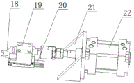
Reference numerals: 1. a frame; 2. a clamping device; 3. a work table; 4. a material guide block; 5. a cover plate; 6. a main shaft; 7. a fixed mount; 8. a belt pulley; 9. a second guide block; 10. a motor; 11. mounting a bracket; 12. a movable plate; 13. a material blocking device; 14. discharging a material block; 15. a bucket shaft sleeve; 16. a conveying device; 17. a second oil cylinder; 18. a clamping block; 19. a push block; 20. a first guide block; 21. an oil cylinder fixing plate; 22. a first oil cylinder; 23. a cylinder; 24. a fixed block; 25. a pressure lever; 26. a return spring; 27. a fixed seat; 28. a stop lever; 29. chamfering cutter; 30. a chip groove; 31. a chip outlet.
Detailed Description
A bucket shaft sleeve chamfering machine of the present invention is further described with reference to fig. 1 to 6.
The utility model provides a fill axle sleeve beveler, includes frame 1, workstation 3, motor 10, main shaft 6, clamping device 2 and dam device 13, characterized by: the worktable 3 is arranged above the frame 1, a material guide block 4 is arranged above the worktable, a bucket shaft sleeve 15 is arranged on the inner side of the material guide block 4, the clamping device 2 is positioned on two sides of the material guide block 4, the clamping device 2 comprises a first oil cylinder 22, a push block 19, a clamping block 18 and a first guide block 20, the push block 19 is detachably connected with a piston of the first oil cylinder 22 and the clamping block 18, an oil cylinder fixing plate 21 is arranged on the outer side of the first oil cylinder 22, the main shaft 6 is arranged above the clamping block 18, a chamfering tool 29 is arranged below the main shaft, belt pulleys 8 are arranged above the main shaft 6 and below the motor 10, a belt is arranged between the two belt pulleys 8, a fixing frame 7 is arranged on the outer side of the belt pulleys, a second oil cylinder 17 is arranged below the fixing frame 7, the second oil cylinder 17 and the motor 10 are positioned in the same direction, and a movable plate 12 is arranged on the, the rear side of the movable plate 12 is provided with a mounting bracket 11, a second guide block 9 is arranged between the mounting bracket 11 and the striker device 13, the striker device 13 is positioned on the left side of the main shaft 6, the striker device 13 comprises a cylinder 23, a fixed block 24, a pressure rod 25, a stop lever 28 and a fixed seat 27, the fixed block 24 is positioned on the outer side of the cylinder 23 and is mounted on the movable plate 12, the stop lever 28 is positioned at the lower end of the pressure rod 25, a return spring 26 is arranged between the stop lever and the fixed seat 27, a discharging block 14 is arranged on the left side of the workbench 3, and a conveying device 16 is arranged below the discharging block 14; the front ends of the two clamping blocks 18 are arc-shaped and matched with the outer surface of the bucket shaft sleeve 15, the workbench 3 and the material guide block 4 are inclined upwards by 45 degrees, the upper surface of the material guide block 4 is provided with a cover plate 5, a scrap groove 30 is formed in the position, corresponding to the main shaft 6, of the material guide block 4, a scrap outlet 31 is formed in the right end of the material outlet block 14, a scrap box is arranged on the inner side of the rack 1 and is located under the scrap outlet 31, the first oil cylinder 22 drives the clamping blocks 18 to move back and forth, and the second oil cylinder 17 drives the main shaft 6 and the motor 10 to move up and down.
The chamfering machine can realize the inner circle chamfering of the bucket shaft sleeve 15 by arranging the clamping device 2 and the chamfering cutter 29, the clamping block 18 is matched with the outer surface of the bucket shaft sleeve 15, the slipping phenomenon caused by two-point clamping can be avoided, a worker only needs to put the bucket shaft sleeve 15 on the material guide block 4, the automatic feeding of the bucket shaft sleeve 15 can be realized by utilizing the worktable 3 to incline 45 degrees and the material stopping device 13, in the processing process, scrap iron can enter a waste material box from the scrap groove 30 and the scrap outlet 31, the subsequent processing of the bucket shaft sleeve 15 cannot be influenced, the conveying device 16 comprises a conveying belt, a mounting frame, a driving motor and the like, the chamfered bucket shaft sleeve 15 can be conveyed into a finished product box, the lifting of the main shaft 6 and the clamping of the clamping block 18 are controlled by oil cylinders, the stop lever 28 is controlled by the air cylinder 23, the automatic processing of the bucket shaft sleeve 15 can be completed only by inputting a processing program, and the strength, the processing efficiency and quality are ensured; in conclusion, the chamfering machine is reasonable in structure arrangement, simple and convenient to operate, high in practicability and only used for chamfering shaft sleeve parts.
The above description is only a preferred embodiment of the present invention, and the protection scope of the present invention is not limited to the above embodiments, and all technical solutions belonging to the idea of the present invention belong to the protection scope of the present invention. It should be noted that modifications and embellishments within the scope of the invention may occur to those skilled in the art without departing from the principle of the invention, and are considered to be within the scope of the invention.
Claims (3)
1. The utility model provides a fill axle sleeve beveler, includes frame, workstation, motor, main shaft, clamping device and dam device, characterized by: the worktable is arranged above the rack, a material guide block is arranged above the worktable, a bucket shaft sleeve is arranged on the inner side of the material guide block, the clamping device is positioned on two sides of the material guide block and comprises a first oil cylinder, a push block, a clamping block and a first guide block, the push block is detachably connected with a piston and the clamping block of the first oil cylinder, an oil cylinder fixing plate is arranged on the outer side of the first oil cylinder, the main shaft is arranged above the clamping block, a chamfering cutter is arranged below the main shaft, belt pulleys are arranged above the main shaft and below the motor, a belt is arranged between the two belt pulleys, a fixing frame is arranged on the outer side of the belt, a second oil cylinder is arranged below the fixing frame, the second oil cylinder and the motor are positioned in the same direction, a movable plate is arranged on the rear side of the main shaft, a mounting bracket is arranged on the rear side of the movable plate, and a second, the material blocking device is positioned on the left side of the main shaft and is arranged on the material guiding block section, the material blocking device comprises an air cylinder, a fixing block, a pressure rod, a stop rod and a fixing seat, the fixing block is positioned on the outer side of the air cylinder, and is arranged on the movable plate, the stop lever is positioned at the lower end of the pressure lever, and a return spring is arranged between the stop lever and the fixed seat, one side of the stop lever close to the main shaft is used for stopping a hopper shaft sleeve after chamfering is finished, a discharging block is arranged on the left side of the workbench, a conveying device is arranged below the discharging blocks, the front ends of the two clamping blocks are arc-shaped, and is matched with the outer surface of the bucket shaft sleeve, the workbench and the material guide block are inclined upwards by 45 degrees, the upper surface of the material guide block is provided with a cover plate, a scrap groove is formed in the position, corresponding to the main shaft, of the material guide block, a scrap outlet is formed in the right end of the material outlet block, and the scrap outlet is communicated with the scrap groove.
2. The bucket shaft sleeve chamfering machine according to claim 1, wherein: the inside of frame is provided with the waste bin, the waste bin is located the bits mouth under.
3. The bucket shaft sleeve chamfering machine according to claim 1, wherein: the oil cylinder drives the clamping block to move back and forth, and the oil cylinder II drives the main shaft and the motor to move up and down.
Priority Applications (1)
| Application Number | Priority Date | Filing Date | Title |
|---|---|---|---|
| CN201811301985.6A CN109175530B (en) | 2018-11-02 | 2018-11-02 | Bucket shaft sleeve chamfering machine |
Applications Claiming Priority (1)
| Application Number | Priority Date | Filing Date | Title |
|---|---|---|---|
| CN201811301985.6A CN109175530B (en) | 2018-11-02 | 2018-11-02 | Bucket shaft sleeve chamfering machine |
Publications (2)
| Publication Number | Publication Date |
|---|---|
| CN109175530A CN109175530A (en) | 2019-01-11 |
| CN109175530B true CN109175530B (en) | 2020-10-16 |
Family
ID=64941637
Family Applications (1)
| Application Number | Title | Priority Date | Filing Date |
|---|---|---|---|
| CN201811301985.6A Active CN109175530B (en) | 2018-11-02 | 2018-11-02 | Bucket shaft sleeve chamfering machine |
Country Status (1)
| Country | Link |
|---|---|
| CN (1) | CN109175530B (en) |
Families Citing this family (2)
| Publication number | Priority date | Publication date | Assignee | Title |
|---|---|---|---|---|
| CN110153478A (en) * | 2019-07-02 | 2019-08-23 | 福建联骏机械有限公司 | A kind of bucket spindle set processing tool and method |
| CN113042779B (en) * | 2021-04-01 | 2022-06-10 | 福建联骏机械有限公司 | Automatic drilling combination machine for axial holes of bucket shaft and using method of automatic drilling combination machine |
Family Cites Families (11)
| Publication number | Priority date | Publication date | Assignee | Title |
|---|---|---|---|---|
| CN200945509Y (en) * | 2006-09-04 | 2007-09-12 | 庄添财 | Pipe fittings automatic leading-in clamping device |
| CN201776499U (en) * | 2010-08-16 | 2011-03-30 | 苏州工业园区凯艺精密科技有限公司 | Automatic pneumatic chamfering machine |
| CN103624548B (en) * | 2013-04-08 | 2016-01-27 | 苏州工业园区凯艺精密科技有限公司 | Orthopedic beveler |
| CN203738057U (en) * | 2014-02-28 | 2014-07-30 | 台州蓝盾机械有限公司 | Automatic drilling machine |
| CN204194865U (en) * | 2014-10-08 | 2015-03-11 | 泛科轴承集团有限公司 | Bearing outer ring porous machine for automatic working |
| CN204137854U (en) * | 2014-10-15 | 2015-02-04 | 金石机器人常州有限公司 | A kind of station blocking mechanism |
| CN206010041U (en) * | 2016-08-27 | 2017-03-15 | 浙江正东机车部件有限公司 | A kind of deburring mechanism of full-automatic lock core burr removal fixture |
| CN206047258U (en) * | 2016-09-20 | 2017-03-29 | 深圳市众恒世讯科技股份有限公司 | Automatic chamfering machine |
| CN206854779U (en) * | 2017-06-08 | 2018-01-09 | 佛山市天凌自动化设备有限公司 | A kind of rectangle square bar beveler |
| CN107414103B (en) * | 2017-08-25 | 2019-01-11 | 浙江力庆制冷设备有限公司 | A kind of beveler |
| CN108098073A (en) * | 2018-02-24 | 2018-06-01 | 王祖友 | A kind of automatic deburring machine for vehicle part |
-
2018
- 2018-11-02 CN CN201811301985.6A patent/CN109175530B/en active Active
Also Published As
| Publication number | Publication date |
|---|---|
| CN109175530A (en) | 2019-01-11 |
Similar Documents
| Publication | Publication Date | Title |
|---|---|---|
| CN109175530B (en) | Bucket shaft sleeve chamfering machine | |
| CN208961140U (en) | Die processing unit bed with automatic clearing function | |
| CN202271013U (en) | Automatic slot milling machine | |
| KR100485120B1 (en) | Auto-riveting machine | |
| KR100994788B1 (en) | Apparatus for cutting burr | |
| CN206343684U (en) | A kind of duplicating milling machine | |
| CN105347029A (en) | Automatic feeding equipment of hydraulic cylinder barrel expanding mill | |
| CN211218697U (en) | Automatic loading and unloading device for numerical control vehicle | |
| CN205222057U (en) | Pneumatic cylinder cylinder expanding machine automatic feeding equipment | |
| CN211588654U (en) | Wheel assembly mills valve hole lathe | |
| CN205057182U (en) | Automatic sawing device of sewing machine connecting rod | |
| CN217433735U (en) | Circular cutting machine for cutting automobile ball cage | |
| CN104552470B (en) | A kind of door pocket plate is combined sawing machine | |
| CN216758669U (en) | Tunnel type muffler inner tube welding set | |
| CN214393413U (en) | Cut-off chamfering machine | |
| CN112296652B (en) | Tooth body assembly devices of isolator | |
| CN214291144U (en) | Automatic double-station sawing machine | |
| CN209792651U (en) | efficient drilling machine | |
| CN209793247U (en) | Drilling machine feeding system | |
| CN207858502U (en) | A kind of control apparatus for general purpose engine deburring component | |
| CN110883423A (en) | Laser cutting machine's frame | |
| CN108942218A (en) | A kind of angle grinder spanner automatic assembling apparatus | |
| CN104942375A (en) | Necking machine used for processing automobile air-conditioning pipe fittings | |
| CN215661295U (en) | Automatic feeding and discharging mechanism | |
| CN110666191A (en) | Machine tool for turning outer circle |
Legal Events
| Date | Code | Title | Description |
|---|---|---|---|
| PB01 | Publication | ||
| PB01 | Publication | ||
| SE01 | Entry into force of request for substantive examination | ||
| SE01 | Entry into force of request for substantive examination | ||
| GR01 | Patent grant | ||
| GR01 | Patent grant |