CN109115669B - A water cycle test device and method for long-term automatic measurement of rock variable permeability - Google Patents
A water cycle test device and method for long-term automatic measurement of rock variable permeability Download PDFInfo
- Publication number
- CN109115669B CN109115669B CN201811143733.5A CN201811143733A CN109115669B CN 109115669 B CN109115669 B CN 109115669B CN 201811143733 A CN201811143733 A CN 201811143733A CN 109115669 B CN109115669 B CN 109115669B
- Authority
- CN
- China
- Prior art keywords
- valve
- water
- water tank
- rock
- pressure
- Prior art date
- Legal status (The legal status is an assumption and is not a legal conclusion. Google has not performed a legal analysis and makes no representation as to the accuracy of the status listed.)
- Active
Links
- XLYOFNOQVPJJNP-UHFFFAOYSA-N water Substances O XLYOFNOQVPJJNP-UHFFFAOYSA-N 0.000 title claims abstract description 156
- 239000011435 rock Substances 0.000 title claims abstract description 60
- 238000012360 testing method Methods 0.000 title claims abstract description 49
- 230000035699 permeability Effects 0.000 title claims abstract description 25
- 238000000034 method Methods 0.000 title claims abstract description 10
- 230000007774 longterm Effects 0.000 title abstract description 15
- 238000005259 measurement Methods 0.000 title abstract description 11
- 239000007924 injection Substances 0.000 claims abstract description 22
- 238000002347 injection Methods 0.000 claims abstract description 22
- 239000007788 liquid Substances 0.000 claims abstract description 19
- 230000008859 change Effects 0.000 claims abstract description 12
- 239000002184 metal Substances 0.000 claims description 9
- 239000011521 glass Substances 0.000 claims description 7
- 238000011010 flushing procedure Methods 0.000 claims description 5
- 238000010998 test method Methods 0.000 claims description 5
- 238000004590 computer program Methods 0.000 claims description 3
- 239000012535 impurity Substances 0.000 claims description 3
- 230000003204 osmotic effect Effects 0.000 claims description 2
- 239000012530 fluid Substances 0.000 abstract description 12
- 230000003628 erosive effect Effects 0.000 abstract description 5
- 230000008569 process Effects 0.000 abstract description 4
- 230000000694 effects Effects 0.000 abstract description 2
- 230000035515 penetration Effects 0.000 description 4
- 238000004891 communication Methods 0.000 description 2
- 238000013480 data collection Methods 0.000 description 2
- 238000012986 modification Methods 0.000 description 2
- 230000004048 modification Effects 0.000 description 2
- 238000007789 sealing Methods 0.000 description 2
- 230000009286 beneficial effect Effects 0.000 description 1
- 238000004364 calculation method Methods 0.000 description 1
- 238000004140 cleaning Methods 0.000 description 1
- 238000005520 cutting process Methods 0.000 description 1
- 238000010586 diagram Methods 0.000 description 1
- 230000008020 evaporation Effects 0.000 description 1
- 238000001704 evaporation Methods 0.000 description 1
- 206010016256 fatigue Diseases 0.000 description 1
- 238000012544 monitoring process Methods 0.000 description 1
- 230000000737 periodic effect Effects 0.000 description 1
- 238000011160 research Methods 0.000 description 1
- 239000000243 solution Substances 0.000 description 1
- 230000002269 spontaneous effect Effects 0.000 description 1
Images


Classifications
-
- G—PHYSICS
- G01—MEASURING; TESTING
- G01N—INVESTIGATING OR ANALYSING MATERIALS BY DETERMINING THEIR CHEMICAL OR PHYSICAL PROPERTIES
- G01N15/00—Investigating characteristics of particles; Investigating permeability, pore-volume or surface-area of porous materials
- G01N15/08—Investigating permeability, pore-volume, or surface area of porous materials
-
- G—PHYSICS
- G01—MEASURING; TESTING
- G01N—INVESTIGATING OR ANALYSING MATERIALS BY DETERMINING THEIR CHEMICAL OR PHYSICAL PROPERTIES
- G01N3/00—Investigating strength properties of solid materials by application of mechanical stress
- G01N3/08—Investigating strength properties of solid materials by application of mechanical stress by applying steady tensile or compressive forces
- G01N3/10—Investigating strength properties of solid materials by application of mechanical stress by applying steady tensile or compressive forces generated by pneumatic or hydraulic pressure
- G01N3/12—Pressure testing
Landscapes
- Chemical & Material Sciences (AREA)
- Biochemistry (AREA)
- Physics & Mathematics (AREA)
- Health & Medical Sciences (AREA)
- Life Sciences & Earth Sciences (AREA)
- Analytical Chemistry (AREA)
- General Health & Medical Sciences (AREA)
- General Physics & Mathematics (AREA)
- Immunology (AREA)
- Pathology (AREA)
- Dispersion Chemistry (AREA)
- Investigation Of Foundation Soil And Reinforcement Of Foundation Soil By Compacting Or Drainage (AREA)
- Investigating Strength Of Materials By Application Of Mechanical Stress (AREA)
Abstract
本发明公开了一种长期自动测量岩石变渗透率的水循环测试装置及方法,测试装置包括:岩样夹持加载系统,包括岩芯夹持器和围压控制系统,待测岩样放置于岩芯夹持器中;循环注液与排液系统,此系统控制流经岩石试样的液体,并形成一个循环回路;定时开关系统,此系统控制注液与排液系统在规定时间启动与关闭,无需操作人员值守控制;数据采集记录系统,此系统包括设置在测试装置中的三个压力变送器、两个质量传感器、一台无纸记录仪和计算机。本发明解决了现有技术中无法研究长期的水流冲蚀作用,且仪器测量量程小,无法适用于渗透率突变的情况和渗透率变化大的测试问题,同时解决了现有技术中测试仪器需要测试人员全程监测、手动操作的技术问题。
The invention discloses a water circulation test device and method for long-term automatic measurement of rock variable permeability. The test device includes: a rock sample clamping and loading system, including a core holder and a confining pressure control system. The rock sample to be tested is placed on a rock In the core holder; circulating fluid injection and drainage system, this system controls the liquid flowing through the rock sample, and forms a circulation loop; time switch system, this system controls the startup and shutdown of the fluid injection and drainage system at a specified time , no need for operator on-duty control; data acquisition and recording system, this system includes three pressure transmitters, two quality sensors, a paperless recorder and a computer set in the test device. The invention solves the problem that the long-term water erosion effect cannot be studied in the prior art, and the measurement range of the instrument is small, so it cannot be applied to the situation of a sudden change in permeability and the test problem of large permeability change, and at the same time solves the need for testing instruments in the prior art. Testers monitor and manually operate technical issues throughout the process.
Description
技术领域technical field
本发明涉及岩石渗透率的测试,特别涉及一种长期自动测量岩石变渗透率的水循环测试装置和测试方法。The invention relates to the test of rock permeability, in particular to a water circulation test device and a test method for long-term automatic measurement of rock variable permeability.
背景技术Background technique
渗透率是指在一定压差下,岩石允许流体通过的能力,长期水流冲刷会使岩体渗透率发生改变。为减小冲蚀作用的灾害损失,对岩石渗透率的长期变化研究十分重要。目前已存的测定岩石渗透率的测试仪器,大多需要操作人员全程值守。每一次测试都需要大量时间、精力和费用。目前已存的测量岩石渗流的仪器大多测量量程范围小,无法研究长时间的水流冲蚀作用造成的渗透率变化大的测试问题。尤其对于突水测试中渗透率急剧突变的情况难以适用。Permeability refers to the ability of rock to allow fluid to pass under a certain pressure difference. Long-term water erosion will change the permeability of rock mass. In order to reduce the disaster loss caused by erosion, it is very important to study the long-term change of rock permeability. Most of the existing testing instruments for measuring rock permeability require operators to be on duty all the time. Each test requires a lot of time, effort and expense. Most of the existing instruments for measuring rock seepage have a small measurement range, and cannot study the test problem of large permeability changes caused by long-term water erosion. It is especially difficult to apply to the situation where the permeability changes suddenly in the water inrush test.
发明内容Contents of the invention
发明目的:针对上述现有技术,提供一种长期自动测量岩石变渗透率的水循环测试装置和测试方法,解决了现有技术中无法研究长期的水流冲蚀作用,且仪器测量量程小,无法适用于大变化渗透率测试问题,同时解决了现有技术中测试仪器需要测试人员全程监测、手动操作的技术问题。Purpose of the invention: Aiming at the above prior art, to provide a water cycle test device and test method for long-term automatic measurement of rock variable permeability, which solves the problem that the long-term water erosion effect cannot be studied in the prior art, and the measuring range of the instrument is too small to be applicable It solves the problem of large-change permeability testing, and at the same time solves the technical problem that testing instruments in the prior art require full monitoring and manual operation by testers.
技术方案:一种长期自动测量岩石变渗透率的水循环测试装置,包括:Technical solution: A water cycle test device for long-term automatic measurement of rock variable permeability, including:
岩样夹持加载系统,所述岩样夹持加载系统包括岩芯夹持器和围压控制系统,待测岩样放置于所述岩芯夹持器中;A rock sample clamping and loading system, the rock sample clamping and loading system includes a core holder and a confining pressure control system, and the rock sample to be tested is placed in the core holder;
循环注液与排液系统,所述循环注液与排液系统用于将液体注入所述岩芯夹持器中,并将液体从所述岩芯夹持器系统中排出,形成一个闭路循环系统;Circulating fluid injection and drainage system, the circulation fluid injection and drainage system is used to inject fluid into the core holder and discharge fluid from the core holder system to form a closed loop system;
定时开关系统,所述定时开关系统用于控制所述循环注液与排液系统开始工作与结束工作的时间;A timing switch system, the timing switch system is used to control the time when the circulation injection and drainage system starts working and ends working;
数据采集记录系统,所述数据采集记录系统用于接收测试数据。A data collection and recording system, the data collection and recording system is used to receive test data.
进一步的,所述循环注液与排液系统包括第三水槽、过滤器、水泵、减压阀、节流阀、储能器、第一截止阀、第一压力变送器、第二截止阀、第二压力变送器、止回阀、若干电磁阀、第一水槽和第二水槽;所述第三水槽通过连通管道依次连接过滤器、水泵、减压阀、节流阀、储能器、第一截止阀,第一截止阀另一端和岩芯夹持器下端相连,岩芯夹持器与第一截止阀之间设置第一压力变送器;岩芯夹持器上端用连通管道依次连接第二截止阀、止回阀,止回阀的输出端分为两路,分别连接到第一电磁阀和第二电磁阀,第一、第二电磁阀出口分别对应放置第一水槽、第二水槽,岩芯夹持器与第二截止阀之间设置第二压力变送器;所述第一水槽和第二水槽内部底端分别对应设置第一排水电磁阀、第二排水电磁阀,第一排水电磁阀和第二排水电磁阀通过排水管连接第三水槽的进水口。Further, the circulating liquid injection and liquid drainage system includes a third water tank, a filter, a water pump, a pressure reducing valve, a throttle valve, an accumulator, a first shut-off valve, a first pressure transmitter, and a second shut-off valve , a second pressure transmitter, a check valve, several solenoid valves, a first water tank and a second water tank; the third water tank is sequentially connected to a filter, a water pump, a pressure reducing valve, a throttle valve, and an accumulator through a communication pipeline 1. The first shut-off valve, the other end of the first shut-off valve is connected to the lower end of the rock core holder, and the first pressure transmitter is arranged between the rock core holder and the first shut-off valve; the upper end of the rock core holder is connected with a connecting pipe Connect the second cut-off valve and check valve in turn. The output end of the check valve is divided into two circuits, which are respectively connected to the first solenoid valve and the second solenoid valve. The outlets of the first and second solenoid valves are respectively placed in the first water tank, The second water tank, the second pressure transmitter is set between the core holder and the second shut-off valve; the first water tank and the inner bottom of the second water tank are respectively provided with a first drain solenoid valve and a second drain solenoid valve , the first drain solenoid valve and the second drain solenoid valve are connected to the water inlet of the third water tank through the drain pipe.
进一步的,所述围压控制系统包括伺服液压油缸、第三截止阀和第三压力变送器,岩芯夹持器与伺服液压油缸连接,伺服液压油缸和岩芯夹持器之间设置第三压力变送器和第三截止阀。Further, the confining pressure control system includes a servo hydraulic cylinder, a third stop valve and a third pressure transmitter, the core holder is connected to the servo hydraulic cylinder, and a first Three pressure transmitters and a third shut-off valve.
进一步的,所述循环注液与排液系统还包括冲水装置,所述冲水装置包括两个浮子开关,两个浮子开关分别位于第一水槽、第二水槽的内壁上部,浮子开关连接电磁阀控制器,由所述电磁阀控制器控制各电磁阀的电源输出;当第一水槽中的水位达到设定高度时,第一水槽中的浮子开关启动,电磁阀控制器关闭第一电磁阀电源和第二电磁排水阀电源,同时开启第二电磁阀电源和第一电磁排水阀电源;当第二水槽中的水位达到设定高度时,第二水槽中的浮子开关启动,电磁阀控制器关闭第二电磁阀电源和第一排水阀电源,同时开启第一电磁阀电源和第二排水电磁阀电源。Further, the circulating liquid injection and draining system also includes a flushing device, the flushing device includes two float switches, the two float switches are respectively located on the upper part of the inner wall of the first water tank and the second water tank, and the float switches are connected to the electromagnetic Valve controller, the power output of each solenoid valve is controlled by the solenoid valve controller; when the water level in the first water tank reaches the set height, the float switch in the first water tank is activated, and the solenoid valve controller closes the first solenoid valve power supply and the second electromagnetic drain valve power supply, open the second electromagnetic valve power supply and the first electromagnetic drain valve power supply at the same time; when the water level in the second water tank reaches the set height, the float switch in the second water tank starts, and the solenoid valve controller Turn off the power supply of the second solenoid valve and the power supply of the first drain valve, and simultaneously turn on the power supply of the first solenoid valve and the power supply of the second drain solenoid valve.
进一步的,所述定时开关系统包括电源和定时器开关插座,所述定时器开关插座连接电源,所述水泵的电源插头插于所述定时器开关插座。Further, the timing switch system includes a power supply and a timer switch socket, the timer switch socket is connected to a power supply, and the power plug of the water pump is inserted into the timer switch socket.
进一步的,所述数据采集记录系统包括第一质量传感器和第二质量传感器、无纸记录仪、计算机,第二水槽和第三水槽分别悬挂于第一质量传感器和第二质量传感器下,第一至第三压力变送器以及第一、第二质量传感器皆与所述无纸记录仪相连,所述无纸记录仪连接计算机。Further, the data acquisition and recording system includes a first mass sensor and a second mass sensor, a paperless recorder, a computer, the second water tank and the third water tank are suspended under the first mass sensor and the second quality sensor respectively, and the first The third pressure transmitter and the first and second quality sensors are all connected to the paperless recorder, and the paperless recorder is connected to a computer.
进一步的,所述的第一水槽、第二水槽和第三水槽皆由透明玻璃制造,所述第三水槽顶部有透明玻璃盖。Further, the first water tank, the second water tank and the third water tank are all made of transparent glass, and the top of the third water tank has a transparent glass cover.
一种长期自动测量岩石变渗透率的水循环测试方法,以水作为渗透介质测试时,包括以下步骤:A long-term water cycle test method for automatically measuring rock variable permeability, when water is used as the penetration medium test, includes the following steps:
步骤1:连接好测试装置,检查装置密封性,关闭所有阀门,确保三个水槽中清洁无杂质,向第三水槽中注入清水;Step 1: Connect the test device, check the tightness of the device, close all valves, ensure that the three water tanks are clean and free of impurities, and pour clean water into the third water tank;
步骤2:将岩样相同直径、高度的金属管装入岩芯夹持器34中,确认岩芯夹持器封闭状况;Step 2: Put a metal tube with the same diameter and height as the rock sample into the
步骤3:连接好工作电路,将各压力变送器和质量传感器数据接入无纸记录仪;Step 3: Connect the working circuit, and connect the data of each pressure transmitter and quality sensor to the paperless recorder;
步骤4:打开第三截止阀,打开伺服液压油缸,将围压增加到工作围压;Step 4: Open the third stop valve, open the servo hydraulic cylinder, and increase the confining pressure to the working confining pressure;
步骤5:打开第一截止阀、第二截止阀,打开水泵,为循环注液与排液系统提供动力;Step 5: Open the first shut-off valve and the second shut-off valve, and turn on the water pump to provide power for the circulating injection and drainage system;
步骤6:通过观测无纸记录仪的记录,调整减压阀和节流阀得到需要的水压和流量,在无式样的情况下得到不同流量下的测试装置的沿程压力损失,并绘制相应曲线,将所对应的数据带入到计算机程序中;Step 6: By observing the records of the paperless recorder, adjust the pressure reducing valve and throttle valve to obtain the required water pressure and flow rate, and obtain the pressure loss along the test device under different flow rates without a sample, and draw the corresponding Curve, bring the corresponding data into the computer program;
步骤7:断开水泵工作电源,将围压降至零,关闭第一截止阀、第二截止阀和第三截止阀,取出金属管;Step 7: Disconnect the working power of the water pump, reduce the confining pressure to zero, close the first shut-off valve, the second shut-off valve and the third shut-off valve, and take out the metal pipe;
步骤8:装入待测试样,重复步骤4-5,根据需要,设置定时开关,确定渗透周期。改变围压值,调整减压阀和节流阀得到需要的水压和流量,等待装置完成设定任务;Step 8: Load the sample to be tested, repeat steps 4-5, and set the timer switch as needed to determine the penetration cycle. Change the confining pressure value, adjust the pressure reducing valve and throttle valve to obtain the required water pressure and flow, and wait for the device to complete the setting task;
步骤9:在不同的围压和水压条件下重复步骤8;Step 9: Repeat step 8 under different confining pressure and water pressure conditions;
步骤10:断开水泵工作电源,将围压降至零,取出试样,装入金属管加压后,水泵吸入清水冲洗整套测试装置;Step 10: Disconnect the working power of the water pump, reduce the confining pressure to zero, take out the sample, put it into a metal tube and pressurize it, and then the water pump sucks clean water to rinse the entire test device;
步骤11:关闭第一截止阀、第二截止阀和第三截止阀,测试结束。Step 11: Close the first shut-off valve, the second shut-off valve and the third shut-off valve, and the test ends.
有益效果:1.本装置创造性的改用测量渗流液体质量的变化来反映其流量变化,该方法将流速的测量范围扩大至现存仪器的数倍,对于突水情况下岩体的渗透率极限变化的研究具有显著优势。Beneficial effects: 1. This device creatively uses the change of the quality of the seepage liquid to reflect the change of its flow rate. This method expands the measurement range of the flow rate to several times that of the existing instrument. For the limit change of the permeability of the rock mass under the condition of water inrush research has significant advantages.
2.本装置具有定时自动启动、关闭开关,可以在无人看守的情况下进行的岩石渗流周期测试,实现数字化控制。2. This device has a timing automatic start and stop switch, which can conduct periodic rock seepage tests without being guarded, and realize digital control.
3.此外本测试装置的测试渗透介质处于一个首尾闭合管道系统中,可以循环不断的进行长达数个月的渗流测试,无需操作人员手动操作。3. In addition, the test permeation medium of this test device is in a head-to-tail closed pipeline system, which can continuously perform seepage tests for several months without manual operation by operators.
4.本装置所有数据均可自动录入无纸记录仪,并载入计算机软件中,得到高精度的数据资料并实时处理相关数据,无需观测读数和手动记录。4. All data of this device can be automatically entered into the paperless recorder and loaded into the computer software to obtain high-precision data and process relevant data in real time, without the need for observation readings and manual recording.
附图说明Description of drawings
图1为本发明一种长期自动测量岩石变渗透率的水循环测试装置的结构示意图;Fig. 1 is the structural representation of a kind of long-term automatic measurement rock variable permeability water circulation testing device of the present invention;
图2为本发明工作电路示意图。Fig. 2 is a schematic diagram of the working circuit of the present invention.
具体实施方式Detailed ways
下面结合附图对本发明做更进一步的解释。The present invention will be further explained below in conjunction with the accompanying drawings.
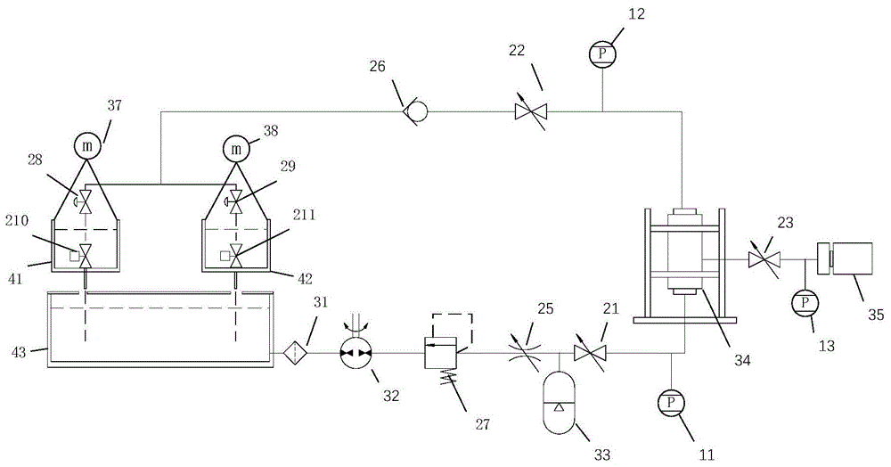
如图1所示,一种长期自动测量岩石变渗透率的水循环测试装置,包括岩样夹持加载系统、循环注液与排液系统、定时开关系统以及数据采集记录系统。岩样夹持加载系统包括岩芯夹持器34、待测岩样放置在岩芯夹持器34中,待测岩石的四周通过岩样夹持加载系统中的伺服液压油缸35加载围压,待测岩样的两端面通过循环注液与排液系统加载渗透压差。As shown in Figure 1, a water cycle test device for long-term automatic measurement of rock variable permeability includes a rock sample clamping and loading system, a circulating fluid injection and drainage system, a timing switch system, and a data acquisition and recording system. The rock sample clamping and loading system includes a
岩样夹持加载系统包括岩芯夹持器34和围压控制系统,待测岩样放置于岩芯夹持器34中,围压控制系统包括伺服液压油缸35、第三截止阀23和第三压力变送器13,岩芯夹持器与伺服液压油缸35连接,伺服液压油缸35和岩芯夹持器之间设置第三压力变送器13和第三截止阀23。The rock sample clamping and loading system includes a
循环注液与排液系统用于将液体注入所述岩芯夹持器34中,并可将液体从所述岩芯夹持器系统中排出,最终形成一个闭路循环系统。循环注液与排液系统包括第三水槽43、过滤器31、水泵32、减压阀27、节流阀25、储能器33、第一截止阀21、第一压力变送器11、第二截止阀22、止回阀26、若干电磁阀、第一水槽41和第二水槽42。第三水槽43的出水口通过密封管道依次连接过滤器31、水泵32、减压阀27、节流阀25、储能器33、第一截止阀21,第一截止阀21输出端和岩芯夹持器34下端相连,岩芯夹持器34与第一截止阀21之间设置第一压力变送器11。岩芯夹持器34上端用连通管道依次连接第二截止阀22、止回阀26,止回阀26的输出端分为两路,分别连接到第一电磁阀28和第二电磁阀29,第一、第二电磁阀出口分别对应放置第一水槽41、第二水槽42,岩芯夹持器34与第二截止阀22之间设置第二压力变送器12。第一水槽41和第二水槽42内部底端分别对应设置第一排水电磁阀210、第二排水电磁阀211,第一排水电磁阀210和第二排水电磁阀211通过排水管连接第三水槽43顶盖的进水口。第一水槽、第二水槽和第三水槽皆由透明玻璃制造且可以拆卸以方便清洗、察看水质以及更换循环液体。第三水槽顶部有透明玻璃盖,减小长期水分蒸发从而避免渗流介质不足的问题,玻璃盖上开有两个进水口,方便渗流液体流进第三水槽。The circulating fluid injection and drainage system is used to inject fluid into the
循环注液与排液系统还包括自动冲水装置,自动冲水装置包括两个浮子开关,两个浮子开关分别位于第一水槽41、第二水槽42的内壁上部,浮子开关连接电磁阀控制器54,由电磁阀控制器54控制第一电磁阀28、第二电磁阀29、第一排水电磁阀210、第二排水电磁阀211的工作。当第一水槽41中的水位达到设定高度时,第一水槽41中的浮子开关启动,电磁阀控制器54关闭第一电磁阀28电源和第二电磁排水阀211电源,同时开启第二电磁阀29电源和第一电磁排水阀210电源。此时第一水槽41开始排水,第二水槽42开始继续承接水流。同理,当第二水槽42中的水位达到设定高度时,第二水槽42中的浮子开关启动,电磁阀控制器54关闭第二电磁阀29电源和第一排水阀210电源,同时开启第一电磁阀28电源和第二排水电磁阀211电源。此时第二水槽42开始排水,第一水槽41开始继续承接水流。The circulating fluid injection and drainage system also includes an automatic flushing device, which includes two float switches, the two float switches are respectively located on the upper inner wall of the
定时开关系统用于控制循环注液与排液系统开始工作与结束工作的时间。定时开关系统包括电源和定时器开关插座53。定时器开关插座53连接电源,水泵33的电源插头连接于定时器开关插座53上,通过定时器开关插座53设置启动和关闭时间,从而控制循环注液与排液系统的接通和断开。The timing switch system is used to control the time when the circulation injection and drainage system starts working and ends working. Time switch system comprises power supply and
数据采集记录系统用于接收一种长期自动测量岩石变渗透率的水循环测试装置中的所有数据。数据采集记录系统包括第一质量传感器37、第二质量传感器38、无纸记录仪52和计算机51,第一至第三压力变送器和两个质量传感器皆与无纸记录仪52相连,无纸记录仪52连接计算机。第二水槽和第三水槽分别悬挂于第一质量传感器37和第二质量传感器38下,第一质量传感器37、第一水槽41和第一排水电磁阀210组成的流量测试单元与第一电磁阀28、第三水槽43均不接触;同理,第二质量传感器38、第二水槽42和第二排水电磁阀211组成的流量测试单元与第二电磁阀29、第三水槽43均不接触。通过质量传感器所测质量变化转换为水流流量变化。无纸记录仪直接接受所有变送器和质量传感器数据,并通过自发计算机软件同步处理测试数据并绘制图像,计算过程中已将装置的沿程压力损失剔除。The data acquisition and recording system is used to receive all the data in a water circulation test device for long-term automatic measurement of rock variable permeability. The data acquisition and recording system comprises a first
以水为渗透介质的测试中,本发明的具体测试方法如下:In the test with water as the penetration medium, the concrete test method of the present invention is as follows:
步骤1:连接好测试装置,检查装置密封性,关闭所有阀门,确保三个水槽中清洁无杂质,向第三水槽中注入清水43;Step 1: Connect the test device, check the tightness of the device, close all valves, ensure that the three water tanks are clean and free of impurities, and pour
步骤2:将岩样相同直径、高度的金属管装入岩芯夹持器34中,确认岩芯夹持器34封闭状况;Step 2: Put a metal tube with the same diameter and height as the rock sample into the
步骤3:连接好工作电路,将各压力变送器和质量传感器数据接入无纸记录仪52;Step 3: Connect the working circuit, and connect the data of each pressure transmitter and mass sensor to the
步骤4:打开第三截止阀23,打开伺服液压油缸35,将围压增加到工作围压;Step 4: Open the third cut-off
步骤5:打开第一截止阀21、第二截止阀22,打开隔膜泵32,为循环注液与排液系统提供动力;Step 5: Open the first shut-off
步骤6:通过观测无纸记录仪52的记录,调整减压阀27和节流阀25得到需要的水压和流量,在无式样的情况下得到不同流量下的测试装置的沿程压力损失,并绘制相应曲线,将所对应的数据带入到计算机程序中;Step 6: By observing the record of the
步骤7:断开水泵32工作电源,将围压降至零,关闭第一截止阀21、第二截止阀22和第三截止阀23,取出金属管;Step 7: Disconnect the working power of the
步骤8:装入待测试样,重复步骤4-5,根据需要,设置定时开关,确定渗透周期。改变围压值,调整减压阀27和节流阀25得到需要的水压和流量,等待装置完成设定任务;Step 8: Load the sample to be tested, repeat steps 4-5, and set the timer switch as needed to determine the penetration cycle. Change the confining pressure value, adjust the
步骤9:在不同的围压和水压条件下重复步骤8;Step 9: Repeat step 8 under different confining pressure and water pressure conditions;
步骤10:断开水泵工作电源,将围压降至零,取出试样,装入金属管加压后,水泵吸入清水冲洗整套测试装置,确保测试设备内无残余岩屑方便后续测试,并用滤纸过滤三个水槽中被冲蚀掉的岩屑便于测试分析;Step 10: Disconnect the working power of the water pump, reduce the confining pressure to zero, take out the sample, put it into a metal tube and pressurize it, and then the water pump sucks clean water to rinse the whole test device to ensure that there is no residual debris in the test device for subsequent testing, and use filter paper Filter the washed-out cuttings in the three tanks for testing and analysis;
步骤11:关闭第一截止阀21、第二截止阀22和第三截止阀23,测试结束。Step 11: Close the first shut-off
以上所述仅是本发明的优选实施方式,应当指出,对于本技术领域的普通技术人员来说,在不脱离本发明原理的前提下,还可以做出若干改进和润饰,这些改进和润饰也应视为本发明的保护范围。The above is only a preferred embodiment of the present invention, it should be pointed out that, for those of ordinary skill in the art, without departing from the principle of the present invention, some improvements and modifications can also be made, and these improvements and modifications can also be made. It should be regarded as the protection scope of the present invention.
Claims (5)
Priority Applications (1)
| Application Number | Priority Date | Filing Date | Title |
|---|---|---|---|
| CN201811143733.5A CN109115669B (en) | 2018-09-29 | 2018-09-29 | A water cycle test device and method for long-term automatic measurement of rock variable permeability |
Applications Claiming Priority (1)
| Application Number | Priority Date | Filing Date | Title |
|---|---|---|---|
| CN201811143733.5A CN109115669B (en) | 2018-09-29 | 2018-09-29 | A water cycle test device and method for long-term automatic measurement of rock variable permeability |
Publications (2)
| Publication Number | Publication Date |
|---|---|
| CN109115669A CN109115669A (en) | 2019-01-01 |
| CN109115669B true CN109115669B (en) | 2023-06-16 |
Family
ID=64857202
Family Applications (1)
| Application Number | Title | Priority Date | Filing Date |
|---|---|---|---|
| CN201811143733.5A Active CN109115669B (en) | 2018-09-29 | 2018-09-29 | A water cycle test device and method for long-term automatic measurement of rock variable permeability |
Country Status (1)
| Country | Link |
|---|---|
| CN (1) | CN109115669B (en) |
Families Citing this family (4)
| Publication number | Priority date | Publication date | Assignee | Title |
|---|---|---|---|---|
| CN111337402A (en) * | 2019-11-01 | 2020-06-26 | 东华大学 | Quick testing arrangement of different thickness fiber fabric in-plane permeability |
| CN112161889A (en) * | 2020-08-28 | 2021-01-01 | 鞍钢集团北京研究院有限公司 | Device and method for testing seawater and sea ice mixture abrasion resistance of steel |
| CN113109230B (en) * | 2021-03-30 | 2022-11-04 | 中国电建集团西北勘测设计研究院有限公司 | Novel earth and rockfill dam construction material seepage deformation test system and method |
| CN113533169A (en) * | 2021-07-28 | 2021-10-22 | 长江水利委员会长江科学院 | Underground water seal oil cave depot surrounding rock wall infiltration collection device |
Citations (9)
| Publication number | Priority date | Publication date | Assignee | Title |
|---|---|---|---|---|
| US4133058A (en) * | 1976-03-02 | 1979-01-09 | Baker William H | Automated pool level and skimming gutter flow control system |
| US4773254A (en) * | 1987-07-07 | 1988-09-27 | Chevron Research Company | Automated steady state relative permeability measurement system |
| CN1963455A (en) * | 2006-11-02 | 2007-05-16 | 中国海洋大学 | Automatic wetting and drying cycle apparatus for corrosion test sample |
| CN203165339U (en) * | 2013-04-01 | 2013-08-28 | 徐州工业职业技术学院 | Multifunctional liquid level control experimental device |
| CN103760087A (en) * | 2014-01-21 | 2014-04-30 | 盐城工学院 | Permeating device for sustainable pressurization of rock body seepage test |
| CN105675469A (en) * | 2016-01-25 | 2016-06-15 | 中国矿业大学 | Full-automatic test system and measurement method for gas permeability of rock |
| CN205826477U (en) * | 2016-07-01 | 2016-12-21 | 重庆科技学院 | A kind of novel core permeability tester |
| CN106872329A (en) * | 2016-12-30 | 2017-06-20 | 中国矿业大学 | A kind of test device and method of testing for surveying Thief zone rock Test Liquid Permeability of Core |
| KR101800383B1 (en) * | 2016-05-16 | 2017-11-23 | 동아대학교 산학협력단 | Isothermal and tri-axial pressure conditioned rock permeability measurement system |
-
2018
- 2018-09-29 CN CN201811143733.5A patent/CN109115669B/en active Active
Patent Citations (9)
| Publication number | Priority date | Publication date | Assignee | Title |
|---|---|---|---|---|
| US4133058A (en) * | 1976-03-02 | 1979-01-09 | Baker William H | Automated pool level and skimming gutter flow control system |
| US4773254A (en) * | 1987-07-07 | 1988-09-27 | Chevron Research Company | Automated steady state relative permeability measurement system |
| CN1963455A (en) * | 2006-11-02 | 2007-05-16 | 中国海洋大学 | Automatic wetting and drying cycle apparatus for corrosion test sample |
| CN203165339U (en) * | 2013-04-01 | 2013-08-28 | 徐州工业职业技术学院 | Multifunctional liquid level control experimental device |
| CN103760087A (en) * | 2014-01-21 | 2014-04-30 | 盐城工学院 | Permeating device for sustainable pressurization of rock body seepage test |
| CN105675469A (en) * | 2016-01-25 | 2016-06-15 | 中国矿业大学 | Full-automatic test system and measurement method for gas permeability of rock |
| KR101800383B1 (en) * | 2016-05-16 | 2017-11-23 | 동아대학교 산학협력단 | Isothermal and tri-axial pressure conditioned rock permeability measurement system |
| CN205826477U (en) * | 2016-07-01 | 2016-12-21 | 重庆科技学院 | A kind of novel core permeability tester |
| CN106872329A (en) * | 2016-12-30 | 2017-06-20 | 中国矿业大学 | A kind of test device and method of testing for surveying Thief zone rock Test Liquid Permeability of Core |
Non-Patent Citations (2)
| Title |
|---|
| 基于PID控制器三容水箱液位的控制设计;杨小强;刘静;黄晓艳;;宁波职业技术学院学报(第04期);全文 * |
| 基于PLC的液体循环控制系统的设计与应用;何立新;徐鹏飞;郝继峰;;中国教育技术装备(第08期);全文 * |
Also Published As
| Publication number | Publication date |
|---|---|
| CN109115669A (en) | 2019-01-01 |
Similar Documents
| Publication | Publication Date | Title |
|---|---|---|
| CN109115669B (en) | A water cycle test device and method for long-term automatic measurement of rock variable permeability | |
| US4215567A (en) | Method and apparatus for testing a production stream | |
| CN1963455A (en) | Automatic wetting and drying cycle apparatus for corrosion test sample | |
| CN103868838B (en) | Soil body osmotic coefficient measuring system | |
| CN202583008U (en) | Hydraulic pressure testing device for pressure pipe | |
| CN109342268B (en) | Quick full-automatic kinematic viscosity measuring device | |
| WO2022007916A1 (en) | Online testing method for integrity of sterilizing filter element | |
| CN107449705A (en) | Concrete permeability resistance on-spot tester | |
| CN110726640B (en) | Automatic determination device for coal sample gas adsorption constant | |
| CN209606283U (en) | It is a kind of for measuring the automatic test device of soil layer infiltration coefficient | |
| CN209182205U (en) | A water circulation test device for long-term automatic measurement of rock variable permeability | |
| CN214174093U (en) | Ceramic flat membrane water flux testing device | |
| CN207894593U (en) | A kind of multi-way valve pressure-resistant test system | |
| CN207717329U (en) | Siphon drainge system testing stand | |
| CN219496362U (en) | Mobile detection equipment for SDI value | |
| CN211411648U (en) | Flat ceramic membrane filtering performance test equipment | |
| RU2470283C2 (en) | Device for sampling from discharge pipeline (versions) | |
| CN110018100A (en) | A kind of varying head infiltration auto testing instrument | |
| CN208762991U (en) | A kind of improved permeameter water system | |
| CN207908256U (en) | A kind of program-controlled efficient pilot system for container class product pressure test | |
| CN111337412A (en) | A multifunctional automatic flexible wall penetration tester and its test method | |
| CN110899262A (en) | Device suitable for offshore platform chemical washing, oil washing and degreasing | |
| CN216815947U (en) | Water hammer test system and test device with the same | |
| CN205280291U (en) | Measurement device for small leakage quantity that lets out of hydraulic component | |
| CN104180877B (en) | A kind of fuel sensor and combination instrument match test platform |
Legal Events
| Date | Code | Title | Description |
|---|---|---|---|
| PB01 | Publication | ||
| PB01 | Publication | ||
| SE01 | Entry into force of request for substantive examination | ||
| SE01 | Entry into force of request for substantive examination | ||
| GR01 | Patent grant | ||
| GR01 | Patent grant |