CN109080552B - Mounting structure of on-vehicle stereo set host computer - Google Patents
Mounting structure of on-vehicle stereo set host computer Download PDFInfo
- Publication number
- CN109080552B CN109080552B CN201811106948.XA CN201811106948A CN109080552B CN 109080552 B CN109080552 B CN 109080552B CN 201811106948 A CN201811106948 A CN 201811106948A CN 109080552 B CN109080552 B CN 109080552B
- Authority
- CN
- China
- Prior art keywords
- guide rail
- vehicle
- mounted sound
- fixing
- main unit
- Prior art date
- Legal status (The legal status is an assumption and is not a legal conclusion. Google has not performed a legal analysis and makes no representation as to the accuracy of the status listed.)
- Active
Links
- 238000009434 installation Methods 0.000 claims abstract description 16
- 230000000149 penetrating effect Effects 0.000 claims abstract description 8
- 230000003014 reinforcing effect Effects 0.000 claims description 4
- 230000000694 effects Effects 0.000 description 4
- 238000010009 beating Methods 0.000 description 2
- 238000004519 manufacturing process Methods 0.000 description 2
- 238000000034 method Methods 0.000 description 2
- 238000004080 punching Methods 0.000 description 2
- 238000010276 construction Methods 0.000 description 1
- 238000012423 maintenance Methods 0.000 description 1
- 238000012986 modification Methods 0.000 description 1
- 230000004048 modification Effects 0.000 description 1
Images

Classifications
-
- B—PERFORMING OPERATIONS; TRANSPORTING
- B60—VEHICLES IN GENERAL
- B60R—VEHICLES, VEHICLE FITTINGS, OR VEHICLE PARTS, NOT OTHERWISE PROVIDED FOR
- B60R11/00—Arrangements for holding or mounting articles, not otherwise provided for
- B60R11/02—Arrangements for holding or mounting articles, not otherwise provided for for radio sets, television sets, telephones, or the like; Arrangement of controls thereof
- B60R11/0217—Arrangements for holding or mounting articles, not otherwise provided for for radio sets, television sets, telephones, or the like; Arrangement of controls thereof for loud-speakers
Landscapes
- Engineering & Computer Science (AREA)
- Mechanical Engineering (AREA)
- Fittings On The Vehicle Exterior For Carrying Loads, And Devices For Holding Or Mounting Articles (AREA)
Abstract
The invention provides an installation structure of a vehicle-mounted sound main unit, which is used for improving the convenience of installation and disassembly of the vehicle-mounted sound main unit. The vehicle-mounted sound equipment main machine is fixed on a vehicle body by utilizing a mounting bracket, the mounting bracket is composed of two guide rails positioned on two sides of the vehicle-mounted sound equipment main machine, the rear end of each guide rail is provided with a clamping groove connected with the corresponding guide rail, and the opening direction of each clamping groove is forward; the front end of the guide rail is provided with a mounting hole, and the axial direction of the mounting hole is parallel to the axial direction of the guide rail; the two sides of the rear end of the vehicle-mounted sound main machine are respectively provided with a protruding guide pillar, the two sides of the front end of the vehicle-mounted sound main machine are respectively provided with a fixing through hole, and the axial direction of the fixing through hole is parallel to the installation direction of the vehicle-mounted sound main machine; the guide post of the vehicle-mounted sound equipment main machine is clamped into the clamping groove along the guide rail, and the vehicle-mounted sound equipment main machine is fixedly connected with the guide rail by using a bolt penetrating through the fixing through hole and the mounting hole; and a guide rail mounting hole is formed below the guide rail, and the guide rail is fixedly connected with the vehicle body by using a bolt penetrating through the guide rail mounting hole.
Description
Technical Field
The invention belongs to the technical field of automobile manufacturing, and particularly relates to an installation structure of a vehicle-mounted sound main unit.
Background
At present, a vehicle-mounted sound system of an automobile is fixed in an instrument panel, the arrangement space is small, the size requirement on the vehicle-mounted sound is smaller and smaller, the requirement on the arrangement position of the vehicle-mounted sound is stricter and stricter, and therefore the sound host size needs to be designed in a minimized mode and is easy to detach, and after-sale maintenance is more convenient.
Disclosure of Invention
The invention aims to provide an installation structure of a vehicle-mounted sound main unit, which is used for improving the convenience of installation and disassembly of the vehicle-mounted sound main unit.
The mounting structure of the vehicle-mounted sound main unit fixes the vehicle-mounted sound main unit on a vehicle body by using a mounting bracket, and is characterized in that the mounting bracket consists of two guide rails positioned at two sides of the vehicle-mounted sound main unit, the rear end of each guide rail is provided with a clamping groove connected with the corresponding guide rail, and the opening direction of each clamping groove is forward; the front end of the guide rail is provided with a mounting hole, and the axial direction of the mounting hole is parallel to the axial direction of the guide rail; the two sides of the rear end of the vehicle-mounted sound main machine are respectively provided with a protruding guide pillar, the two sides of the front end of the vehicle-mounted sound main machine are respectively provided with a fixing through hole, and the axial direction of the fixing through hole is parallel to the installation direction of the vehicle-mounted sound main machine; the guide post of the vehicle-mounted sound equipment main machine is clamped into the clamping groove along the guide rail, and the vehicle-mounted sound equipment main machine is fixedly connected with the guide rail by using a bolt penetrating through the fixing through hole and the mounting hole; and a guide rail mounting hole is formed below the guide rail, and the guide rail is fixedly connected with the vehicle body by using a bolt penetrating through the guide rail mounting hole.
During assembly, the guide pillar of the vehicle-mounted sound host is carried on the edge of the front end of the guide rail, the vehicle-mounted sound host is pushed backwards along the guide rail until the guide pillar of the vehicle-mounted sound host is clamped in the clamping groove at the rear end of the guide rail, the host is assembled in place at the moment, the fixing through hole of the vehicle-mounted sound host is connected with the mounting hole of the guide rail, and finally the guide rail and the vehicle-mounted sound host are fixedly connected by penetrating the fixing through hole and the mounting hole through bolts to complete assembly. The guide rail plays the effect that the direction was supported in the assembling process, and the draw-in groove not only plays the effect that supports the rear end of on-vehicle stereo set host computer, the extreme position of on-vehicle stereo set host computer has still been restricted, and can prevent the rear end of on-vehicle stereo set host computer from upwards beating, make people only utilize the bolt fastening can guarantee the stability of on-vehicle stereo set host computer at the front end of on-vehicle stereo set host computer, the installation procedure has been simplified, and is same, only need to unscrew the bolt of front end when dismantling on-vehicle stereo set host computer, forward along the guide rail pulling on-vehicle stereo set host computer can.
Further, the draw-in groove is by preceding downward sloping gradually backward, forms certain contained angle with the guide rail, when slight not hard up appears in the bolt of fixed on-vehicle stereo set host computer, the guide pillar is owing to receive the resistance of draw-in groove, can't remove along the axial of bolt (the direction of guide rail promptly), only when the not hard up degree of bolt is great to on-vehicle stereo set host computer can be round when the bolt position rotates, the draw-in groove just can be deviate from to the guide pillar and remove along the guide rail, just so improved the reliability of on-vehicle stereo set host computer installation.
Further, for convenient manufacturing and guarantee the reliability that mounting hole and guide rail are connected, the guide rail is formed by the panel punching press, and the front end of guide rail is buckled in order to form first stationary plane, the mounting hole sets up on first stationary plane.
Furthermore, the upper end of the first fixing surface is provided with a convex part protruding forwards, the mounting hole is formed in the lower portion of the convex part, positioning holes for the convex part to penetrate through are formed in the two sides of the front end of the vehicle-mounted sound host machine above the fixing through holes, and after the vehicle-mounted sound host machine is installed in place, the convex part of the guide rail can be inserted into the positioning holes of the vehicle-mounted sound host machine, so that support is provided for the front end of the vehicle-mounted sound host machine, an assembler can guarantee the stability of the vehicle-mounted sound host machine without holding the vehicle-mounted sound host machine with hands, and the operation of screwing bolts is greatly.
Furthermore, the lower end of the guide rail and the two sides of the clamping groove are both punched to form flanges, and reinforcing ribs are arranged at the connecting positions of the clamping groove and the guide rail so as to improve the strength of the guide rail.
Furthermore, the fixing plates are mounted on two sides of the front end of the vehicle-mounted sound main unit through screws, the side portions of the fixing plates are bent to form a second fixing surface perpendicular to the axial direction of the vehicle-mounted sound main unit, and the positioning holes and the fixing through holes are formed in the second fixing surface. The guide post is provided with a stud and is installed on the side face of the vehicle-mounted sound box main machine in a threaded fit mode. With fixed plate, guide pillar all with on-vehicle stereo set host computer components of a whole that can function independently design, just so can increase fixed plate, guide pillar with traditional on-vehicle stereo set host computer and realize swift convenient mounting structure, and need not to customize on-vehicle stereo set host computer specially, improved the commonality.
According to the invention, the installation of the vehicle-mounted sound equipment main machine is designed to be a matching mode of the guide pillar and the guide rail, so that the convenience of installation and disassembly of the vehicle-mounted sound equipment main machine is greatly improved, the man-hour for installation and disassembly is saved, and the vehicle-mounted sound equipment main machine has good practicability.
Drawings
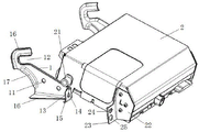
Fig. 1 is a schematic structural view of a mounting structure of a car audio main unit according to the present invention when it is not assembled.
Fig. 2 is a schematic structural view of the mounting structure of the car audio main unit according to the present invention after assembly.
The figures are numbered: 1. a guide rail; 11. a guide rail mounting hole; 12. a card slot; 13. a first fixing surface; 14. mounting holes; 15. a convex portion; 16. flanging; 17. reinforcing ribs; 2. a vehicle-mounted sound equipment host; 21. a guide post; 22. a fixing plate; 23. a second stationary surface; 24. positioning holes; 25. a fixing through hole; 3. and (4) bolts.
Detailed Description
The following describes embodiments of the present invention, such as shapes and structures of respective members, mutual positions and connection relationships between respective portions, and actions and operation principles of the respective portions, in further detail, with reference to the accompanying drawings.
Example 1:
this embodiment has proposed the mounting structure of a car audio host computer to improve the convenience that the installation of car audio host computer was dismantled.
As shown in fig. 1 and 2, the mounting structure of the car audio main unit of the present embodiment is to fix the car audio main unit 2 on the car body by using a mounting bracket, and is characterized in that the mounting bracket is composed of two guide rails 1 located on both sides of the car audio main unit 2, the guide rails 1 are integrally formed by punching plates, a guide rail mounting hole 11 is provided below the guide rail 1, and the guide rail 1 is fixedly connected to the car body by using a bolt penetrating through the guide rail mounting hole 11. The rear end of the guide rail 1 is provided with a clamping groove 12 connected with the guide rail 1, the clamping groove 12 gradually inclines downwards from front to back and forms a certain included angle with the guide rail 1, and the opening direction of the clamping groove 12 is forward; the front end of the guide rail 1 is bent to form a first fixing surface 13, the first fixing surface 13 is provided with a mounting hole 14, a sheet-shaped convex part 15 protruding forwards is arranged above the mounting hole 14, and the axial direction of the mounting hole 14 is parallel to the axial direction of the guide rail 1.
The rear end of the vehicle-mounted sound system main machine 2 is provided with protruding guide pillars 21 through thread matching, the front end of the vehicle-mounted sound system main machine 2 is provided with fixing plates 22 through screws, the side of each fixing plate 22 is bent to form a second fixing surface 23 perpendicular to the axial direction of the vehicle-mounted sound system main machine 2, the second fixing surfaces 23 are provided with positioning holes 24 and fixing through holes 25 from top to bottom, the axial direction of the fixing through holes 25 is parallel to the mounting direction of the vehicle-mounted sound system main machine 2, the positioning holes 24 correspond to the positions of the convex portions 15 of the guide rails 1, and the fixing through holes 25 correspond to the positions of the mounting holes 14 of the guide rails 1.
The guide post 21 of the car audio main unit 2 is inserted into the slot 12 along the guide rail 1, and the car audio main unit 2 is fixedly connected with the guide rail 1 by the bolt 3 passing through the fixing through hole 25 and the mounting hole 14.
During assembly, firstly, the guide post 21 of the vehicle-mounted sound main machine 2 is carried on the edge of the front end of the guide rail 1, the vehicle-mounted sound main machine 2 is pushed backwards along the guide rail 1 until the guide post 21 of the vehicle-mounted sound main machine 2 is clamped in the clamping groove 12 at the rear end of the guide rail 1, the main machine is assembled in place at the moment, the fixing through hole 25 of the vehicle-mounted sound main machine 2 is connected with the mounting hole 14 of the guide rail 1, and finally, the bolt 3 penetrates through the fixing through hole 25 and the mounting hole 14 to fixedly connect the guide rail 1 with the vehicle-mounted sound main machine 2.
After the vehicle-mounted sound main unit 2 is installed in place, the convex portion 15 of the guide rail 1 is inserted into the positioning hole 24 of the vehicle-mounted sound main unit 2, so that support is provided for the front end of the vehicle-mounted sound main unit 2, an assembler can guarantee the stability of the vehicle-mounted sound main unit 2 without holding the vehicle-mounted sound main unit 2 by hands, and operation of screwing the bolt 3 is greatly facilitated.
When slight not hard up appears in the bolt 3 of fixed on-vehicle stereo set host computer 2, guide pillar 21 is because the resistance that receives draw-in groove 12, can't remove along the axial of bolt 3 (the direction of guide rail 1 promptly), and only when the not hard up degree of bolt 3 is great to when on-vehicle stereo set host computer 2 can rotate round bolt 3 position, guide pillar 21 just can deviate from draw-in groove 12 and remove along guide rail 1, has just so improved the reliability of on-vehicle stereo set host computer 2 installation.
The invention has been described in connection with the accompanying drawings, it is to be understood that the invention is not limited in its application to the details of construction and the arrangement of the components set forth in the following description, as long as the invention is capable of being practiced without modification in any way whatsoever, and is capable of other applications without departing from the spirit and scope of the invention as defined by the appended claims.
Claims (4)
1. A mounting structure of a vehicle-mounted sound main unit is characterized in that the vehicle-mounted sound main unit is fixed on a vehicle body by utilizing a mounting bracket, the mounting bracket is composed of two guide rails positioned on two sides of the vehicle-mounted sound main unit, the rear end of each guide rail is provided with a clamping groove connected with the corresponding guide rail, and the opening direction of each clamping groove is forward; the front end of the guide rail is provided with a mounting hole, and the axial direction of the mounting hole is parallel to the axial direction of the guide rail; the two sides of the rear end of the vehicle-mounted sound main machine are respectively provided with a protruding guide pillar, the two sides of the front end of the vehicle-mounted sound main machine are respectively provided with a fixing through hole, and the axial direction of the fixing through hole is parallel to the installation direction of the vehicle-mounted sound main machine; the guide post of the vehicle-mounted sound equipment main machine is clamped into the clamping groove along the guide rail, and the vehicle-mounted sound equipment main machine is fixedly connected with the guide rail by using a bolt penetrating through the fixing through hole and the mounting hole; a guide rail mounting hole is formed below the guide rail, and the guide rail is fixedly connected with the vehicle body through a bolt penetrating through the guide rail mounting hole; the clamping groove is characterized in that the clamping groove gradually inclines downwards from front to back; the guide rail is formed by stamping a plate, the front end of the guide rail is bent to form a first fixing surface, and the mounting hole is formed in the first fixing surface; the upper end of the first fixing surface is provided with a convex part protruding forwards, the mounting hole is formed below the convex part, and positioning holes for the convex part to penetrate through are formed in the two sides of the front end of the vehicle-mounted sound main unit above the fixing through holes.
2. The mounting structure of a vehicle audio main unit according to claim 1, wherein flanges are stamped and formed at the lower end of the guide rail and at both sides of the engaging groove, and a reinforcing rib is provided at a joint of the engaging groove and the guide rail.
3. The mounting structure of a car audio main unit according to claim 1, wherein fixing plates are mounted on both sides of a front end of the car audio main unit by screws, the fixing plates are bent laterally to form a second fixing surface perpendicular to an axial direction of the car audio main unit, and the positioning holes and the fixing through holes are provided in the second fixing surface.
4. The mounting structure of a car audio main unit according to claim 1, wherein the guide post is provided with a stud and is mounted on a side surface of the car audio main unit by screw-fitting.
Priority Applications (1)
| Application Number | Priority Date | Filing Date | Title |
|---|---|---|---|
| CN201811106948.XA CN109080552B (en) | 2018-09-21 | 2018-09-21 | Mounting structure of on-vehicle stereo set host computer |
Applications Claiming Priority (1)
| Application Number | Priority Date | Filing Date | Title |
|---|---|---|---|
| CN201811106948.XA CN109080552B (en) | 2018-09-21 | 2018-09-21 | Mounting structure of on-vehicle stereo set host computer |
Publications (2)
| Publication Number | Publication Date |
|---|---|
| CN109080552A CN109080552A (en) | 2018-12-25 |
| CN109080552B true CN109080552B (en) | 2021-06-29 |
Family
ID=64842257
Family Applications (1)
| Application Number | Title | Priority Date | Filing Date |
|---|---|---|---|
| CN201811106948.XA Active CN109080552B (en) | 2018-09-21 | 2018-09-21 | Mounting structure of on-vehicle stereo set host computer |
Country Status (1)
| Country | Link |
|---|---|
| CN (1) | CN109080552B (en) |
Families Citing this family (1)
| Publication number | Priority date | Publication date | Assignee | Title |
|---|---|---|---|---|
| CN111712076A (en) * | 2020-06-16 | 2020-09-25 | 汉腾汽车有限公司 | An installation structure suitable for the electrical module inside the instrument panel |
Citations (4)
| Publication number | Priority date | Publication date | Assignee | Title |
|---|---|---|---|---|
| CN104409243A (en) * | 2014-11-20 | 2015-03-11 | 厦门宏发开关设备有限公司 | Mounting structure for appliance guide rail |
| CN205220539U (en) * | 2015-12-01 | 2016-05-11 | 广东杰成电子科技有限公司 | Detachable car audio and video navigator |
| CN106585511A (en) * | 2016-11-17 | 2017-04-26 | 绍兴丰源节能科技有限公司 | Embedded type automobile navigation instrument convenient to disassemble and assemble |
| CN207433299U (en) * | 2017-11-02 | 2018-06-01 | 重庆长安汽车股份有限公司 | The mounting structure of recreation terminal host |
Family Cites Families (7)
| Publication number | Priority date | Publication date | Assignee | Title |
|---|---|---|---|---|
| CN2599903Y (en) * | 2003-01-18 | 2004-01-14 | 鸿富锦精密工业(深圳)有限公司 | Hard disk fixed structure |
| CN102999120A (en) * | 2011-09-16 | 2013-03-27 | 鸿富锦精密工业(深圳)有限公司 | Data storage fixing device |
| CN203391705U (en) * | 2013-08-21 | 2014-01-15 | 惠州华阳通用电子有限公司 | Adjustable vehicle-mounted sound system installation structure |
| US20180170275A1 (en) * | 2016-12-20 | 2018-06-21 | Aamp Of Florida, Inc. | Multiple temperature sensor car radio installation kit |
| CN206691032U (en) * | 2017-05-22 | 2017-12-01 | 重庆车车盈网络科技有限公司 | Vehicle-carrying display screen fixing device |
| CN207399442U (en) * | 2017-11-21 | 2018-05-22 | 重庆赛帕斯汽车零部件有限公司 | A kind of automobile using loudspeaker mask assembly |
| CN207737220U (en) * | 2017-12-19 | 2018-08-17 | 车质尚(北京)汽车制造有限公司 | A kind of folding type computer desk |
-
2018
- 2018-09-21 CN CN201811106948.XA patent/CN109080552B/en active Active
Patent Citations (4)
| Publication number | Priority date | Publication date | Assignee | Title |
|---|---|---|---|---|
| CN104409243A (en) * | 2014-11-20 | 2015-03-11 | 厦门宏发开关设备有限公司 | Mounting structure for appliance guide rail |
| CN205220539U (en) * | 2015-12-01 | 2016-05-11 | 广东杰成电子科技有限公司 | Detachable car audio and video navigator |
| CN106585511A (en) * | 2016-11-17 | 2017-04-26 | 绍兴丰源节能科技有限公司 | Embedded type automobile navigation instrument convenient to disassemble and assemble |
| CN207433299U (en) * | 2017-11-02 | 2018-06-01 | 重庆长安汽车股份有限公司 | The mounting structure of recreation terminal host |
Also Published As
| Publication number | Publication date |
|---|---|
| CN109080552A (en) | 2018-12-25 |
Similar Documents
| Publication | Publication Date | Title |
|---|---|---|
| JP5611716B2 (en) | Plate module fixing structure | |
| CN109080552B (en) | Mounting structure of on-vehicle stereo set host computer | |
| CN101812952A (en) | Automobile door hinge capable of being conveniently detached and installed | |
| CN102406346A (en) | Drawer board connection structure | |
| KR20210066959A (en) | Fender insulation for vehicles | |
| CN117792248B (en) | Profile mounting assembly, photovoltaic system and photovoltaic system mounting method | |
| CN210351867U (en) | Electromechanical bottom box fixing components | |
| CN210680600U (en) | Vehicle-mounted all-in-one machine mounting structure | |
| CN203698141U (en) | Vehicle and electric appliance module installing support thereof | |
| CN104210435B (en) | Gap covering device for steering column cover | |
| EP1869725A1 (en) | Roof antenna for a vehicle with improved baseplate and contacting | |
| CN202624098U (en) | A connection structure between an automobile interior panel and a vehicle body | |
| CN216300968U (en) | Mounting structure for bus display | |
| CN218352883U (en) | Fixing structure capable of simplifying process and convenient to disassemble and assemble | |
| CN221031896U (en) | Net piece middle section reinforcement structure and rail system | |
| CN104141666A (en) | Folding wing type buckle for fixing sound insulation pad on front wall plate of automobile | |
| CN220349618U (en) | Door backplate subassembly and vehicle | |
| CN216162957U (en) | Vehicle-mounted active safety monitoring box convenient to assemble | |
| CN216844099U (en) | Firm type wallboard of cement plant easy equipment | |
| CN215922316U (en) | Fixed bolster, steering oil pipe subassembly and vehicle | |
| CN220764300U (en) | Vehicle-mounted electrical device installation structure and vehicle | |
| CN220871107U (en) | Panel structure and air conditioner | |
| CN219938248U (en) | Fixtures for photovoltaic systems and photovoltaic systems | |
| CN223793494U (en) | Photovoltaic noise barriers and photovoltaic systems | |
| CN223559588U (en) | On-vehicle intelligence ceiling television fixed knot constructs |
Legal Events
| Date | Code | Title | Description |
|---|---|---|---|
| PB01 | Publication | ||
| PB01 | Publication | ||
| SE01 | Entry into force of request for substantive examination | ||
| SE01 | Entry into force of request for substantive examination | ||
| GR01 | Patent grant | ||
| GR01 | Patent grant |