CN109036600B - Active and passive combined reactor cavity water injection cooling system debugging method - Google Patents
Active and passive combined reactor cavity water injection cooling system debugging method Download PDFInfo
- Publication number
- CN109036600B CN109036600B CN201810627770.7A CN201810627770A CN109036600B CN 109036600 B CN109036600 B CN 109036600B CN 201810627770 A CN201810627770 A CN 201810627770A CN 109036600 B CN109036600 B CN 109036600B
- Authority
- CN
- China
- Prior art keywords
- water injection
- reactor cavity
- debugging
- test
- cavity water
- Prior art date
- Legal status (The legal status is an assumption and is not a legal conclusion. Google has not performed a legal analysis and makes no representation as to the accuracy of the status listed.)
- Active
Links
Images

Classifications
-
- G—PHYSICS
- G21—NUCLEAR PHYSICS; NUCLEAR ENGINEERING
- G21C—NUCLEAR REACTORS
- G21C17/00—Monitoring; Testing ; Maintaining
- G21C17/001—Mechanical simulators
-
- G—PHYSICS
- G21—NUCLEAR PHYSICS; NUCLEAR ENGINEERING
- G21C—NUCLEAR REACTORS
- G21C15/00—Cooling arrangements within the pressure vessel containing the core; Selection of specific coolants
- G21C15/18—Emergency cooling arrangements; Removing shut-down heat
- G21C15/182—Emergency cooling arrangements; Removing shut-down heat comprising powered means, e.g. pumps
-
- Y—GENERAL TAGGING OF NEW TECHNOLOGICAL DEVELOPMENTS; GENERAL TAGGING OF CROSS-SECTIONAL TECHNOLOGIES SPANNING OVER SEVERAL SECTIONS OF THE IPC; TECHNICAL SUBJECTS COVERED BY FORMER USPC CROSS-REFERENCE ART COLLECTIONS [XRACs] AND DIGESTS
- Y02—TECHNOLOGIES OR APPLICATIONS FOR MITIGATION OR ADAPTATION AGAINST CLIMATE CHANGE
- Y02E—REDUCTION OF GREENHOUSE GAS [GHG] EMISSIONS, RELATED TO ENERGY GENERATION, TRANSMISSION OR DISTRIBUTION
- Y02E30/00—Energy generation of nuclear origin
- Y02E30/30—Nuclear fission reactors
Abstract
The invention relates to a debugging method of an active and passive combined reactor cavity water injection cooling system, which is based on the active and passive combined design characteristics of the reactor cavity water injection cooling system, and by analyzing each function and configuration of the system, designs debugging test items to be carried out by the system, the scheme and content of the specific implementation of the debugging test, the acceptance criteria of each test, the execution stage and the mutual execution logic sequence, including the debugging of system single equipment, the debugging of system independent sub-functions and the debugging of system comprehensive performance. The method can comprehensively and efficiently verify the functions of the system and the conformity with the design target of the system, and provides powerful guarantee for ensuring that the reactor cavity water injection cooling system can fully play the inherent role when a severe accident occurs in the nuclear power plant.
Description
Technical Field
The invention belongs to the debugging design technology of a nuclear power plant, and particularly relates to a debugging method of a reactor cavity water injection cooling system with active and passive combination.
Background
The debugging of the nuclear power plant refers to all activities to be executed when a structure, a system and components enter a certain operation mode after the installation work is basically finished so as to comprehensively verify the design, equipment manufacturing, construction and installation quality of the nuclear power plant and ensure that the nuclear power plant can continuously and stably operate under rated power, and the whole process mainly comprises two parts, namely a non-nuclear test and a nuclear test. The debugging is the last step of the construction phase and the first step of the operation phase of the nuclear power plant, and the comprehensiveness, safety and effectiveness of the debugging test are important for the safe and reliable operation of the nuclear power plant.
After the nuclear accident of the Japan Fudao, according to the adjustment of the nuclear energy policy of China and the development of the international trend, the nuclear power station of the advanced pressurized water reactor with higher safety and stronger accident resistance is adopted in the newly built domestic nuclear power station. The advanced pressurized water reactor nuclear power station firstly improves the overall safety of the nuclear power station from the design angle, introduces new concept design and items with new design characteristics, and comprises an active and passive combined reactor cavity water injection cooling system. The reactor cavity water injection cooling system has the functions that after a serious accident of reactor core melting occurs, the heat of reactor core molten material is taken away through cooling outside the pressure vessel, the temperature of the outer wall of the reactor pressure vessel is reduced, the integrity of the pressure vessel is maintained, and the retention of the reactor core molten material in the pressure vessel is realized. The reactor cavity water injection cooling system of the advanced pressurized water reactor nuclear power plant comprises an active part and a passive part, wherein the active part injects water into the reactor cavity by a water injection cooling pump to cool the reactor pressure container, and the passive part injects water into the reactor cavity by gravity to cool the reactor pressure container under the condition that the active part is unavailable.
As a process system adopting a new concept design in an advanced pressurized water reactor nuclear power plant, the functions of a reactor cavity water injection cooling system need to be debugged before the reactor cavity water injection cooling system is put into operation formally. The design, equipment manufacture and installation of the whole system are comprehensively checked to meet the design requirements and meet the system performance standard by analyzing and designing complete test items, accurate and easily-judged acceptance criteria and reasonable test logics and test stages, so that the whole system is ensured to play the inherent role of limiting the consequences of accidents when serious accidents occur in the nuclear power plant. However, in the design manual and the related literature of the system, how to perform the debugging test of the system is not specifically described, and the technical requirements of debugging are not explained; and a system which is newly designed and combines active and passive is adopted, and no debugging experience can be adopted and used for reference.
Disclosure of Invention
The invention aims to provide a debugging method of an advanced pressurized water reactor nuclear power plant reactor cavity water injection cooling system aiming at the design characteristic that the advanced pressurized water reactor nuclear power plant reactor cavity water injection cooling system is actively combined with non-active power, so that the performability and reasonability of system debugging work are ensured.
The technical scheme of the invention is as follows: a debugging method of a reactor cavity water injection cooling system combining active and passive comprises the following steps:
(1) analyzing the functions of the reactor cavity water injection cooling system, and decomposing the system configuration;
(2) based on the function analysis and configuration decomposition of the system, the debugging technical requirements of the single equipment test of the system are obtained according to the composition design of system equipment and components;
(3) designing and obtaining the technical requirements of independent test debugging of the system subfunction according to the functional attributes of the system and the composition of the system subfunction (active reactor cavity water injection and passive reactor cavity water injection);
(4) determining the technical requirement for debugging the comprehensive performance of the system on the basis of the function of the reactor cavity water injection cooling system in the aspects of ensuring the safety of the nuclear power station or limiting the accident consequence and combining the technical requirement for debugging the independent test of the system subfunction;
(5) and determining a principle of system debugging, namely firstly developing a single test of a single component and equipment, further developing an independent test of the sub-functions, finally developing a comprehensive performance test of the system, and designing the execution stage of each debugging test item of the reactor cavity water injection cooling system and the execution logic sequence of each debugging test item according to the prerequisite condition required by each test execution.
Further, according to the debugging method of the active and passive combined reactor cavity water injection cooling system, the system configuration in the step (1) comprises an active part and a passive part, the active part comprises two series which are arranged in parallel, each series is provided with a reactor cavity water injection cooling pump and an electric isolating valve, and the reactor cavity water injection cooling pump absorbs water from a containment built-in refueling water tank or a fire water tank and injects the water into the reactor cavity; the passive part comprises a passive reactor cavity water injection tank and four electric isolation valves.
Further, according to the debugging method of the active and passive combined reactor cavity water injection cooling system, the debugging items of the system single equipment test in the step (2) include: the method comprises the steps of pipeline flushing of a reactor cavity water injection cooling system, instrument and simulation control function tests, logic control channel tests, electric isolating valve tests and motor tests of a reactor cavity water injection cooling pump.
Further, in the active and passive combined reactor cavity water injection cooling system debugging method, the debugging items of the system sub-function independent test in the step (3) include: a reactor cavity water injection cooling pump small flow test and a passive reactor cavity water injection tank test.
Further, in the active and passive combined reactor cavity water injection cooling system debugging method, the items for debugging the comprehensive performance of the system in the step (4) include: the method comprises an active reactor cavity water injection flow verification test, a passive reactor cavity water injection flow verification test and a reactor pressure vessel and heat insulation layer gap verification test.
Furthermore, according to the debugging method of the active and passive combined reactor cavity water injection cooling system, the active reactor cavity water injection flow verification test and the passive reactor cavity water injection flow verification test in the step (4) are both completed through a bypass drainage pipeline, and cooling water is not directly injected into the reactor cavity; the verification test of the clearance between the reactor pressure vessel and the heat insulation layer is to check the smoothness of a flow channel by injecting compressed air to supplement and verify the direct injection of the flow of the reactor cavity.
Further, according to the debugging method of the active and passive combined reactor cavity water injection cooling system, in the step (5), the stages of each debugging test of the system to be executed and the logic sequence of each debugging test project to be executed are determined according to the installation progress of system equipment and components, the plan of debugging work and the time requirement for putting the system into operation.
The invention has the following beneficial effects:
(1) the invention not only needs to analyze the system function, but also needs to decompose the system configuration. The reactor cavity water injection cooling system is characterized in that the reactor cavity water injection cooling system combining active and passive is analyzed from two aspects of component and equipment composition of the system and sub-function composition of the system, so that reference and basis are provided for design of subsequent system monomer equipment debugging technical requirements, system independent sub-function debugging technical requirements and system comprehensive performance debugging technical requirements. The analysis of system functions and the decomposition of system configuration can ensure the comprehensiveness, integrity and reasonability of the design of debugging test project setting and debugging technical requirements.
(2) The invention designs the debugging technical requirements of the single equipment for the single equipment and the components of the system based on the system function and the configuration analysis result. The design process of the debugging technical requirements of the single equipment of the system not only covers all equipment and parts of the system, but also ensures the comprehensiveness and the integrity of the debugging technical requirement design; the transfer of work content and responsibility of the nuclear power station process system from the installation stage to the debugging stage are embodied, and the clear limitation, clear task and no omission of work content connection of the responsibility of the installation unit and the responsibility of the debugging unit are ensured.
(3) The invention is based on the functional attribute and the independent subfunction of the system, and designs the necessary debugging technical requirement to verify that the independent subfunction of the system meets the requirement of the system functional design. The method starts from the minimum unit of the system function, gradually develops debugging work according to the principle of firstly partially and then integrally, not only can provide a blueprint for the design of the next system comprehensive performance debugging technical requirement, but also can adjust each independent sub-function of the system to the optimal running state as much as possible through a debugging test, and provides guarantee for the development of the subsequent system comprehensive performance debugging. In addition, in order to protect important equipment from being damaged during debugging, a flow test of the reactor cavity water injection cooling pump is executed in a small-flow test pipeline mode, water in an outlet pipeline of the water injection cooling pump returns to the built-in refueling water tank through the small-flow pipeline during the test, and damage to pump body components caused by overhigh pressure or suppressed pressure of the outlet of the pump is avoided.
(4) The design of the system comprehensive performance debugging technical requirement ensures that the functions of the system in the aspects of nuclear power station safety guarantee or accident consequence limitation are effectively verified on one hand, and also ensures that the execution of the debugging test cannot cause the damage of nuclear power station equipment and the personal injury of workers on the other hand. In order to find a reasonable balance point between the reactor pressure vessel and the heat preservation layer, active and passive reactor cavity water injection flow is verified in a bypass drainage pipeline mode, and then a reactor pressure vessel and heat preservation layer gap verification test (the reactor cavity is directly injected with compressed air instead of water to check the smoothness of a flow channel) is performed to verify that reactor cavity flow injection meets design requirements, so that system functions are effectively verified, and meanwhile, the risk of damage to the reactor pressure vessel heat preservation layer and personnel hazard caused by direct injection of water into the reactor cavity is avoided.
(5) On the basis of the basic principle of debugging work execution and the sequence matching relation of the test execution, the invention comprehensively analyzes the installation progress of system equipment and components, the plan arrangement of the debugging work and the time requirement of the system for putting into operation to determine the implementation stage and the logic sequence of each debugging test, and ensures the performability and the reasonability of the debugging work of the system.
Drawings
FIG. 1 is a logic diagram of a debugging method of an advanced pressurized water reactor nuclear power plant reactor cavity water injection cooling system according to the present invention;
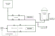
FIG. 2 is a schematic configuration diagram of an advanced pressurized water reactor nuclear power plant reactor cavity water injection cooling system.
Detailed Description
The invention is described in detail below with reference to the figures and examples.
The system debugging aims to enable structures, components and systems of the nuclear power plant to operate, verify that the performance of the structures, the components and the systems meets design requirements and meets performance standards, and all the systems and functions of the nuclear power plant can be put into operation after debugging tests are executed and test results meet design criteria. The reactor cavity water injection cooling system is used as an active and passive combined system which is designed by adopting a new concept in an advanced pressurized water reactor nuclear power plant, and no related debugging experience can be used for reference and reference. The invention provides a design method for debugging technical requirements of a reactor cavity water injection cooling system of an advanced pressurized water reactor nuclear power plant. The method is based on the design characteristics of the active and passive combination of the reactor cavity water injection cooling system, and by analyzing each function and configuration of the system, the debugging test items to be developed by the system, the scheme and content of the specific implementation of the debugging test, the acceptance criteria of each test and the logic sequence of the mutual execution are designed. As shown in FIG. 1, the debugging and designing method of the active and passive combined reactor cavity water injection cooling system provided by the invention comprises the following steps:
(1) system function and configuration resolution
After a severe accident of core melting occurs, the reactor cavity water injection cooling system combining active and passive takes away the heat of core melt through cooling outside the pressure vessel, reduces the temperature of the outer wall of the reactor pressure vessel, maintains the integrity of the pressure vessel, and realizes the retention of the core melt in the pressure vessel.
As shown in fig. 2, the active part of the system is provided with two series connected in parallel, each series is provided with a reactor cavity water injection cooling pump and an electric isolation valve, when a serious accident occurs, water in a refueling water tank or a fire water tank arranged in a containment vessel is injected into a pressure vessel heat insulation layer in the reactor cavity to cool the outer wall surface of the pressure vessel of the reactor, so that the heat of molten materials in a reactor core is led out, the pressure vessel is ensured not to be melted through, the integrity of the pressure vessel is maintained, and the consequence of the accident is reduced.
The passive part of the system is arranged in a containment, in order to ensure the reliability of water injection of a passive reactor cavity and prevent the system from being put into practice by mistake, four parallel electric isolation valves are arranged as isolation parts, and under the condition that the active injection part is unavailable, water in a water injection tank of the passive reactor cavity in the containment can be injected into a heat insulation layer of a pressure vessel in the reactor cavity by gravity to submerge a lower end socket of the pressure vessel of the reactor to a certain height and compensate the evaporation capacity of the water in the reactor cavity, so that the pressure vessel of the reactor is cooled in a passive mode.
(2) System single equipment debugging technical requirement design
The single equipment test project of the reactor cavity water injection cooling system combining active and passive mainly comprises the following steps: the method comprises the steps of pipeline flushing of a reactor cavity water injection cooling system, instrument and simulation control function testing, logic control channel testing, electric isolating valve testing and reactor cavity water injection pump motor testing. Wherein:
the pipeline flushing of the reactor cavity water injection cooling system is to flush desalted and deoxidized water after the installation of the components, equipment and pipelines of the system is finished, so as to discharge impurities, dirt and foreign matters in the system and achieve the specified cleanliness requirement.
The instrument and simulation control function test is used for testing the performances of sensors and actuating mechanisms of instruments and control systems in the system, and verifying that hardware and software meet requirements and the like.
The logic control channel test is used for testing the performance of an actuator and a contactor of an instrument and a control system and the correct logic of signal processing.
The electric isolating valve test is a function test of the electric isolating valve under the condition of no fluid, and comprises the steps of checking the availability of a limit switch and the stroke of a valve rod and measuring the action time.
The reactor cavity water injection pump motor test mainly checks the rotation direction, the electrical parameters and the vibration level of the motor and the temperature of the bearing and the winding after stable operation.
(3) System independent sub-function debugging technical requirement design
The independent subfunction test project of the reactor cavity water injection cooling system combining the active and the passive mainly comprises a reactor cavity water injection cooling pump small flow test and a passive reactor cavity water injection tank test. Wherein:
the reactor cavity water injection cooling pump small flow test is that the electric parameters, vibration parameters, temperature parameters and flow of the water injection cooling pump are measured through a small flow test pipeline of an active part, and the obtained data is verified to be the same as the values provided in an equipment operation and maintenance manual of the pump;
the passive reactor cavity water injection tank test aims at verifying the water level setting value of the reactor cavity water injection tank and related alarm signals and verifying the purification and water supplement functions.
(4) System comprehensive performance debugging technical requirement design
The comprehensive performance test projects of the reactor cavity water injection cooling system combining the active and the passive mainly comprise an active reactor cavity water injection flow verification test, a passive reactor cavity water injection flow verification test and a reactor pressure vessel and heat insulation layer gap verification test. Wherein:
the active reactor cavity water injection flow verification test is to verify that the electrical, hydraulic and mechanical parameters of a pump meet design requirements through a bypass drainage pipeline under the rated working condition of a water injection cooling pump (namely at the rated flow of the pump).
The passive reactor cavity water injection flow verification test is used for verifying passive reactor cavity water injection flow, calibrating related pore plates and verifying isolation performance of an electric isolation valve, and is also completed through a bypass drainage pipeline.
The verification test of the clearance between the reactor pressure vessel and the heat insulation layer verifies that the clearance between the reactor pressure vessel and the heat insulation layer is smooth by injecting compressed air instead of directly injecting water.
(5) System debugging test project logic sequence and execution phase design
According to the installation schedule of system equipment and components, the schedule of debugging work and the time for putting the system into operation, the active and passive combined reactor cavity water injection cooling system is required to be completed before the unit performs a primary circuit hydraulic test, and all tests of the reactor cavity water injection cooling system are required to be completed in a primary test sub-stage because the primary circuit hydraulic test is performed immediately after the primary test sub-stage is finished.
On the premise of ensuring the safety of nuclear power plants and the safety of workers and equipment of nuclear power plants, the invention analyzes the design characteristics of the reactor cavity water injection cooling system and the actual requirements of the system debugging work execution, and carries out detailed description aiming at the debugging technical requirements of the system.
It will be apparent to those skilled in the art that various changes and modifications may be made in the present invention without departing from the spirit and scope of the invention. Thus, if such modifications and variations of the present invention fall within the scope of the claims of the present invention and their equivalents, the present invention is intended to include such modifications and variations.
Claims (7)
1. A debugging method of a reactor cavity water injection cooling system combining active and passive comprises the following steps:
(1) analyzing the functions of the reactor cavity water injection cooling system, and decomposing the system configuration;
(2) based on the function analysis and configuration decomposition of the system, the debugging technical requirements of the single equipment test of the system are obtained according to the composition design of system equipment and components;
(3) designing to obtain the technical requirements of independent test debugging of the system subfunctions according to the functional attributes of the system and the composition of the system subfunctions;
(4) determining the technical requirement for debugging the comprehensive performance of the system on the basis of the function of the reactor cavity water injection cooling system in the aspects of ensuring the safety of the nuclear power station or limiting the accident consequence and combining the technical requirement for debugging the independent test of the system subfunction;
(5) and determining a principle of system debugging, namely firstly developing a single test of a single component and equipment, further developing an independent test of sub-functions, finally developing a comprehensive performance test of the system, and designing a logic sequence and an execution stage for executing each debugging test item of the reactor cavity water injection cooling system according to prerequisites required by executing each test.
2. The debugging method of the active and passive combined reactor cavity water injection cooling system according to claim 1, characterized in that: the system configuration in the step (1) comprises an active part and a passive part, wherein the active part comprises two series which are arranged in parallel, each series is provided with a reactor cavity water injection cooling pump and an electric isolation valve, and the reactor cavity water injection cooling pump absorbs water from a containment built-in refueling water tank or a fire water tank and injects the water into a reactor cavity; the passive part comprises a passive reactor cavity water injection tank and four electric isolation valves.
3. The debugging method of the active and passive combined reactor cavity water injection cooling system according to claim 1, characterized in that: the debugging items of the system single equipment test in the step (2) comprise: the method comprises the steps of pipeline flushing of a reactor cavity water injection cooling system, instrument and simulation control function tests, logic control channel tests, electric isolating valve tests and motor tests of a reactor cavity water injection cooling pump.
4. The debugging method of the active and passive combined reactor cavity water injection cooling system according to claim 1, characterized in that: the debugging items of the system sub-function independent test in the step (3) comprise: a reactor cavity water injection cooling pump small flow test and a passive reactor cavity water injection tank test.
5. The debugging method of the active and passive combined reactor cavity water injection cooling system according to claim 1, characterized in that: the project for debugging the comprehensive performance of the system in the step (4) comprises the following steps: the method comprises an active reactor cavity water injection flow verification test, a passive reactor cavity water injection flow verification test and a reactor pressure vessel and heat insulation layer gap verification test.
6. The debugging method of the active and passive combined reactor cavity water injection cooling system according to claim 5, characterized in that: the active reactor cavity water injection flow verification test and the passive reactor cavity water injection flow verification test in the step (4) are both completed through a bypass drainage pipeline, and cooling water is not directly injected into the reactor cavity; the verification test of the clearance between the reactor pressure vessel and the heat insulation layer is to check the smoothness of a flow channel by injecting compressed air to supplement and verify the direct injection of the flow of the reactor cavity.
7. The debugging method of the active and passive combined reactor cavity water injection cooling system according to claim 1, characterized in that: and (5) determining the stages of the system to be executed by each debugging test and the logic sequence of the execution of each debugging test item according to the installation progress of the system equipment and the components, the debugging work plan and the time requirement for putting the system into operation.
Priority Applications (1)
| Application Number | Priority Date | Filing Date | Title |
|---|---|---|---|
| CN201810627770.7A CN109036600B (en) | 2018-06-19 | 2018-06-19 | Active and passive combined reactor cavity water injection cooling system debugging method |
Applications Claiming Priority (1)
| Application Number | Priority Date | Filing Date | Title |
|---|---|---|---|
| CN201810627770.7A CN109036600B (en) | 2018-06-19 | 2018-06-19 | Active and passive combined reactor cavity water injection cooling system debugging method |
Publications (2)
| Publication Number | Publication Date |
|---|---|
| CN109036600A CN109036600A (en) | 2018-12-18 |
| CN109036600B true CN109036600B (en) | 2021-09-17 |
Family
ID=64609579
Family Applications (1)
| Application Number | Title | Priority Date | Filing Date |
|---|---|---|---|
| CN201810627770.7A Active CN109036600B (en) | 2018-06-19 | 2018-06-19 | Active and passive combined reactor cavity water injection cooling system debugging method |
Country Status (1)
| Country | Link |
|---|---|
| CN (1) | CN109036600B (en) |
Families Citing this family (4)
| Publication number | Priority date | Publication date | Assignee | Title |
|---|---|---|---|---|
| CN110931141A (en) * | 2019-11-13 | 2020-03-27 | 中国核电工程有限公司 | Debugging method for passive containment heat exporting system |
| CN112259274A (en) * | 2020-09-11 | 2021-01-22 | 中国核电工程有限公司 | Debugging method for middle-long-term heat-extraction cooling water system after nuclear power plant accident |
| CN112489842A (en) * | 2020-11-04 | 2021-03-12 | 中国核电工程有限公司 | Combined alarm method for active actuating mechanism of reactor cavity water injection cooling system |
| CN114548649A (en) * | 2021-12-28 | 2022-05-27 | 福建福清核电有限公司 | Active reactor cavity water injection system availability evaluation method combined with passive reactor cavity water injection system |
Citations (5)
| Publication number | Priority date | Publication date | Assignee | Title |
|---|---|---|---|---|
| CN101996130A (en) * | 2009-08-13 | 2011-03-30 | 上海杉达学院 | Software testing system |
| CN103168277A (en) * | 2010-08-31 | 2013-06-19 | Abb技术有限公司 | Method for debugging of process or manufacturing plant solutions comprising multiple sub-systems |
| CN104267283A (en) * | 2014-09-26 | 2015-01-07 | 上海科梁信息工程有限公司 | Platform and method for testing process layer to spacer layer of digital substation |
| CN105304148A (en) * | 2015-09-21 | 2016-02-03 | 国核工程有限公司 | Method for completeness evaluation of nuclear power plant debugging test projects |
| CN106093616A (en) * | 2016-05-30 | 2016-11-09 | 中国核电工程有限公司 | A kind of formulating method for advanced pressurized water reactor nuclear power plant debugging stage head heap pilot project |
-
2018
- 2018-06-19 CN CN201810627770.7A patent/CN109036600B/en active Active
Patent Citations (5)
| Publication number | Priority date | Publication date | Assignee | Title |
|---|---|---|---|---|
| CN101996130A (en) * | 2009-08-13 | 2011-03-30 | 上海杉达学院 | Software testing system |
| CN103168277A (en) * | 2010-08-31 | 2013-06-19 | Abb技术有限公司 | Method for debugging of process or manufacturing plant solutions comprising multiple sub-systems |
| CN104267283A (en) * | 2014-09-26 | 2015-01-07 | 上海科梁信息工程有限公司 | Platform and method for testing process layer to spacer layer of digital substation |
| CN105304148A (en) * | 2015-09-21 | 2016-02-03 | 国核工程有限公司 | Method for completeness evaluation of nuclear power plant debugging test projects |
| CN106093616A (en) * | 2016-05-30 | 2016-11-09 | 中国核电工程有限公司 | A kind of formulating method for advanced pressurized water reactor nuclear power plant debugging stage head heap pilot project |
Also Published As
| Publication number | Publication date |
|---|---|
| CN109036600A (en) | 2018-12-18 |
Similar Documents
| Publication | Publication Date | Title |
|---|---|---|
| CN109036600B (en) | Active and passive combined reactor cavity water injection cooling system debugging method | |
| EP3090433B1 (en) | Nuclear reactor protection systems and methods | |
| KR20020034011A (en) | Digital online active test plant protection system and method for nuclear power plant | |
| JP2013501945A (en) | General-purpose sensor self-diagnosis device and diagnosis method thereof | |
| CN110931141A (en) | Debugging method for passive containment heat exporting system | |
| CN103700411A (en) | Method and system for dealing with loss of coolant accident (LOCA) of nuclear power station | |
| Kwon et al. | Technical review on the localized digital instrumentation and control systems | |
| CN116147878B (en) | Large-scale low-temperature wind tunnel safety interlocking method, device and storage medium | |
| CN107843507A (en) | A kind of environment fatigue test method with notched specimen | |
| CN102096635A (en) | Accurate positioning method for software bug | |
| CN112259274A (en) | Debugging method for middle-long-term heat-extraction cooling water system after nuclear power plant accident | |
| CN103578590A (en) | Nuclear power station power-losing accident analysis method and system | |
| CN110085339B (en) | Main pump risk analysis method and device, computer equipment and storage medium | |
| CN107256787A (en) | A kind of dual transformer Buchholz relay device and application method for exempting from dismounting experiment | |
| CN103514312B (en) | A kind of compressed air system forfeiture and the analysis method of consequence | |
| Ayoub et al. | Simplified/harmonized PSA: a generic modeling framework | |
| Bai et al. | A hybrid fatigue analysis method for fatigue monitor system | |
| Liang et al. | Study on aging management of operating nuclear power plants in China | |
| Tikkala et al. | Test Case Selection Procedure for Simulation-Assisted Automation Testing | |
| Huang et al. | Discussion on application of reliability-centered maintenance to reliability improvement in new nuclear power plants | |
| CN112330124A (en) | Method and system for evaluating influence of accident environment on uncertainty of instrument channel | |
| Chen et al. | The application of fault tree analysis method in electrical component | |
| CN116500435A (en) | Intelligent gas relay aging test analysis system, method, medium and terminal | |
| Yu et al. | A Post-accident Operating State Monitoring and Tracing System for Primary Circuit in Nuclear Power Plants | |
| Leea et al. | Development of Software Test-based Reliability Assessment Method for Nuclear Power Plant Safety-critical Software |
Legal Events
| Date | Code | Title | Description |
|---|---|---|---|
| PB01 | Publication | ||
| PB01 | Publication | ||
| SE01 | Entry into force of request for substantive examination | ||
| SE01 | Entry into force of request for substantive examination | ||
| GR01 | Patent grant | ||
| GR01 | Patent grant |