EP3090433B1 - Nuclear reactor protection systems and methods - Google Patents
Nuclear reactor protection systems and methods Download PDFInfo
- Publication number
- EP3090433B1 EP3090433B1 EP14880292.9A EP14880292A EP3090433B1 EP 3090433 B1 EP3090433 B1 EP 3090433B1 EP 14880292 A EP14880292 A EP 14880292A EP 3090433 B1 EP3090433 B1 EP 3090433B1
- Authority
- EP
- European Patent Office
- Prior art keywords
- safety
- modules
- trip
- inputs
- esfas
- Prior art date
- Legal status (The legal status is an assumption and is not a legal conclusion. Google has not performed a legal analysis and makes no representation as to the accuracy of the status listed.)
- Active
Links
- 238000000034 method Methods 0.000 title claims description 43
- 230000006854 communication Effects 0.000 claims description 74
- 238000004891 communication Methods 0.000 claims description 74
- 230000009471 action Effects 0.000 claims description 65
- 230000003213 activating effect Effects 0.000 claims description 2
- 230000006870 function Effects 0.000 description 116
- 238000000926 separation method Methods 0.000 description 49
- 238000013461 design Methods 0.000 description 39
- 231100000279 safety data Toxicity 0.000 description 28
- 230000001681 protective effect Effects 0.000 description 25
- 238000012360 testing method Methods 0.000 description 24
- 230000008569 process Effects 0.000 description 22
- 238000012544 monitoring process Methods 0.000 description 20
- 238000010586 diagram Methods 0.000 description 18
- 230000000977 initiatory effect Effects 0.000 description 18
- 239000002826 coolant Substances 0.000 description 16
- 238000004458 analytical method Methods 0.000 description 14
- 230000001052 transient effect Effects 0.000 description 14
- 238000005259 measurement Methods 0.000 description 13
- 238000005516 engineering process Methods 0.000 description 11
- 230000007123 defense Effects 0.000 description 9
- 230000000694 effects Effects 0.000 description 7
- 230000036961 partial effect Effects 0.000 description 7
- 238000004630 atomic force microscopy Methods 0.000 description 6
- 230000004907 flux Effects 0.000 description 6
- 238000002955 isolation Methods 0.000 description 6
- 238000012423 maintenance Methods 0.000 description 6
- 229910052796 boron Inorganic materials 0.000 description 5
- 230000003750 conditioning effect Effects 0.000 description 5
- 238000001816 cooling Methods 0.000 description 5
- 230000004044 response Effects 0.000 description 5
- XLYOFNOQVPJJNP-UHFFFAOYSA-N water Substances O XLYOFNOQVPJJNP-UHFFFAOYSA-N 0.000 description 5
- 230000002547 anomalous effect Effects 0.000 description 4
- 230000001419 dependent effect Effects 0.000 description 4
- 238000001514 detection method Methods 0.000 description 4
- 230000000737 periodic effect Effects 0.000 description 4
- 230000000704 physical effect Effects 0.000 description 4
- ZOXJGFHDIHLPTG-UHFFFAOYSA-N Boron Chemical compound [B] ZOXJGFHDIHLPTG-UHFFFAOYSA-N 0.000 description 3
- 230000002159 abnormal effect Effects 0.000 description 3
- 230000008901 benefit Effects 0.000 description 3
- 230000001627 detrimental effect Effects 0.000 description 3
- 238000001914 filtration Methods 0.000 description 3
- 230000000670 limiting effect Effects 0.000 description 3
- 230000001902 propagating effect Effects 0.000 description 3
- 230000001105 regulatory effect Effects 0.000 description 3
- 238000012546 transfer Methods 0.000 description 3
- 230000004075 alteration Effects 0.000 description 2
- 230000003466 anti-cipated effect Effects 0.000 description 2
- 238000013459 approach Methods 0.000 description 2
- 238000009835 boiling Methods 0.000 description 2
- 230000008878 coupling Effects 0.000 description 2
- 238000010168 coupling process Methods 0.000 description 2
- 238000005859 coupling reaction Methods 0.000 description 2
- 230000018109 developmental process Effects 0.000 description 2
- 238000011156 evaluation Methods 0.000 description 2
- 239000000835 fiber Substances 0.000 description 2
- 239000007788 liquid Substances 0.000 description 2
- 238000004519 manufacturing process Methods 0.000 description 2
- 239000000463 material Substances 0.000 description 2
- 230000000116 mitigating effect Effects 0.000 description 2
- 238000005381 potential energy Methods 0.000 description 2
- 238000012545 processing Methods 0.000 description 2
- 239000012857 radioactive material Substances 0.000 description 2
- 238000012795 verification Methods 0.000 description 2
- RYGMFSIKBFXOCR-UHFFFAOYSA-N Copper Chemical compound [Cu] RYGMFSIKBFXOCR-UHFFFAOYSA-N 0.000 description 1
- 229910052692 Dysprosium Inorganic materials 0.000 description 1
- 229910052691 Erbium Inorganic materials 0.000 description 1
- 229910052693 Europium Inorganic materials 0.000 description 1
- 229910052688 Gadolinium Inorganic materials 0.000 description 1
- 229910052772 Samarium Inorganic materials 0.000 description 1
- BQCADISMDOOEFD-UHFFFAOYSA-N Silver Chemical compound [Ag] BQCADISMDOOEFD-UHFFFAOYSA-N 0.000 description 1
- 239000000654 additive Substances 0.000 description 1
- 230000000996 additive effect Effects 0.000 description 1
- 230000002411 adverse Effects 0.000 description 1
- 229910045601 alloy Inorganic materials 0.000 description 1
- 239000000956 alloy Substances 0.000 description 1
- 230000004888 barrier function Effects 0.000 description 1
- 230000007175 bidirectional communication Effects 0.000 description 1
- 230000002457 bidirectional effect Effects 0.000 description 1
- 230000005540 biological transmission Effects 0.000 description 1
- 229910052793 cadmium Inorganic materials 0.000 description 1
- BDOSMKKIYDKNTQ-UHFFFAOYSA-N cadmium atom Chemical compound [Cd] BDOSMKKIYDKNTQ-UHFFFAOYSA-N 0.000 description 1
- 230000001364 causal effect Effects 0.000 description 1
- 230000008859 change Effects 0.000 description 1
- 238000006243 chemical reaction Methods 0.000 description 1
- 238000005253 cladding Methods 0.000 description 1
- 229910017052 cobalt Inorganic materials 0.000 description 1
- 239000010941 cobalt Substances 0.000 description 1
- GUTLYIVDDKVIGB-UHFFFAOYSA-N cobalt atom Chemical compound [Co] GUTLYIVDDKVIGB-UHFFFAOYSA-N 0.000 description 1
- 230000000295 complement effect Effects 0.000 description 1
- 150000001875 compounds Chemical class 0.000 description 1
- 230000001276 controlling effect Effects 0.000 description 1
- 229910052802 copper Inorganic materials 0.000 description 1
- 239000010949 copper Substances 0.000 description 1
- 230000007547 defect Effects 0.000 description 1
- 238000011161 development Methods 0.000 description 1
- KBQHZAAAGSGFKK-UHFFFAOYSA-N dysprosium atom Chemical compound [Dy] KBQHZAAAGSGFKK-UHFFFAOYSA-N 0.000 description 1
- UYAHIZSMUZPPFV-UHFFFAOYSA-N erbium Chemical compound [Er] UYAHIZSMUZPPFV-UHFFFAOYSA-N 0.000 description 1
- OGPBJKLSAFTDLK-UHFFFAOYSA-N europium atom Chemical compound [Eu] OGPBJKLSAFTDLK-UHFFFAOYSA-N 0.000 description 1
- 230000004992 fission Effects 0.000 description 1
- 238000011990 functional testing Methods 0.000 description 1
- UIWYJDYFSGRHKR-UHFFFAOYSA-N gadolinium atom Chemical compound [Gd] UIWYJDYFSGRHKR-UHFFFAOYSA-N 0.000 description 1
- 229910052735 hafnium Inorganic materials 0.000 description 1
- VBJZVLUMGGDVMO-UHFFFAOYSA-N hafnium atom Chemical compound [Hf] VBJZVLUMGGDVMO-UHFFFAOYSA-N 0.000 description 1
- 238000010438 heat treatment Methods 0.000 description 1
- 229910052738 indium Inorganic materials 0.000 description 1
- APFVFJFRJDLVQX-UHFFFAOYSA-N indium atom Chemical compound [In] APFVFJFRJDLVQX-UHFFFAOYSA-N 0.000 description 1
- 238000002347 injection Methods 0.000 description 1
- 239000007924 injection Substances 0.000 description 1
- 230000003993 interaction Effects 0.000 description 1
- 230000007774 longterm Effects 0.000 description 1
- 230000005012 migration Effects 0.000 description 1
- 238000013508 migration Methods 0.000 description 1
- 239000003758 nuclear fuel Substances 0.000 description 1
- 230000003287 optical effect Effects 0.000 description 1
- 230000000644 propagated effect Effects 0.000 description 1
- 230000009257 reactivity Effects 0.000 description 1
- 230000002829 reductive effect Effects 0.000 description 1
- 230000002441 reversible effect Effects 0.000 description 1
- 238000012552 review Methods 0.000 description 1
- KZUNJOHGWZRPMI-UHFFFAOYSA-N samarium atom Chemical compound [Sm] KZUNJOHGWZRPMI-UHFFFAOYSA-N 0.000 description 1
- 238000005070 sampling Methods 0.000 description 1
- 230000008054 signal transmission Effects 0.000 description 1
- 229910052709 silver Inorganic materials 0.000 description 1
- 239000004332 silver Substances 0.000 description 1
- 238000003860 storage Methods 0.000 description 1
- 239000000126 substance Substances 0.000 description 1
- 238000006467 substitution reaction Methods 0.000 description 1
- 230000008093 supporting effect Effects 0.000 description 1
- 230000033772 system development Effects 0.000 description 1
- 230000007704 transition Effects 0.000 description 1
- 238000013024 troubleshooting Methods 0.000 description 1
- 238000010977 unit operation Methods 0.000 description 1
- 238000010200 validation analysis Methods 0.000 description 1
- 230000008016 vaporization Effects 0.000 description 1
Images


Classifications
-
- G—PHYSICS
- G21—NUCLEAR PHYSICS; NUCLEAR ENGINEERING
- G21C—NUCLEAR REACTORS
- G21C9/00—Emergency protection arrangements structurally associated with the reactor, e.g. safety valves provided with pressure equalisation devices
-
- G—PHYSICS
- G21—NUCLEAR PHYSICS; NUCLEAR ENGINEERING
- G21D—NUCLEAR POWER PLANT
- G21D3/00—Control of nuclear power plant
- G21D3/001—Computer implemented control
-
- G—PHYSICS
- G05—CONTROLLING; REGULATING
- G05B—CONTROL OR REGULATING SYSTEMS IN GENERAL; FUNCTIONAL ELEMENTS OF SUCH SYSTEMS; MONITORING OR TESTING ARRANGEMENTS FOR SUCH SYSTEMS OR ELEMENTS
- G05B9/00—Safety arrangements
- G05B9/02—Safety arrangements electric
- G05B9/03—Safety arrangements electric with multiple-channel loop, i.e. redundant control systems
-
- G—PHYSICS
- G21—NUCLEAR PHYSICS; NUCLEAR ENGINEERING
- G21C—NUCLEAR REACTORS
- G21C7/00—Control of nuclear reaction
- G21C7/36—Control circuits
-
- G—PHYSICS
- G21—NUCLEAR PHYSICS; NUCLEAR ENGINEERING
- G21D—NUCLEAR POWER PLANT
- G21D3/00—Control of nuclear power plant
- G21D3/04—Safety arrangements
-
- G—PHYSICS
- G05—CONTROLLING; REGULATING
- G05B—CONTROL OR REGULATING SYSTEMS IN GENERAL; FUNCTIONAL ELEMENTS OF SUCH SYSTEMS; MONITORING OR TESTING ARRANGEMENTS FOR SUCH SYSTEMS OR ELEMENTS
- G05B9/00—Safety arrangements
- G05B9/02—Safety arrangements electric
-
- G—PHYSICS
- G06—COMPUTING; CALCULATING OR COUNTING
- G06F—ELECTRIC DIGITAL DATA PROCESSING
- G06F1/00—Details not covered by groups G06F3/00 - G06F13/00 and G06F21/00
- G06F1/26—Power supply means, e.g. regulation thereof
- G06F1/28—Supervision thereof, e.g. detecting power-supply failure by out of limits supervision
-
- G—PHYSICS
- G21—NUCLEAR PHYSICS; NUCLEAR ENGINEERING
- G21C—NUCLEAR REACTORS
- G21C17/00—Monitoring; Testing ; Maintaining
-
- G—PHYSICS
- G21—NUCLEAR PHYSICS; NUCLEAR ENGINEERING
- G21D—NUCLEAR POWER PLANT
- G21D3/00—Control of nuclear power plant
- G21D3/04—Safety arrangements
- G21D3/06—Safety arrangements responsive to faults within the plant
-
- H—ELECTRICITY
- H02—GENERATION; CONVERSION OR DISTRIBUTION OF ELECTRIC POWER
- H02H—EMERGENCY PROTECTIVE CIRCUIT ARRANGEMENTS
- H02H3/00—Emergency protective circuit arrangements for automatic disconnection directly responsive to an undesired change from normal electric working condition with or without subsequent reconnection ; integrated protection
- H02H3/02—Details
- H02H3/05—Details with means for increasing reliability, e.g. redundancy arrangements
-
- Y—GENERAL TAGGING OF NEW TECHNOLOGICAL DEVELOPMENTS; GENERAL TAGGING OF CROSS-SECTIONAL TECHNOLOGIES SPANNING OVER SEVERAL SECTIONS OF THE IPC; TECHNICAL SUBJECTS COVERED BY FORMER USPC CROSS-REFERENCE ART COLLECTIONS [XRACs] AND DIGESTS
- Y02—TECHNOLOGIES OR APPLICATIONS FOR MITIGATION OR ADAPTATION AGAINST CLIMATE CHANGE
- Y02E—REDUCTION OF GREENHOUSE GAS [GHG] EMISSIONS, RELATED TO ENERGY GENERATION, TRANSMISSION OR DISTRIBUTION
- Y02E30/00—Energy generation of nuclear origin
- Y02E30/30—Nuclear fission reactors
Definitions
- a first aspect combinable with the general implementation further includes limiting, with one of the plurality of functionally independent modules, a single failure propagation to any other of the plurality of functionally independent modules.
- a nuclear reactor protection system includes a plurality of functionally independent modules, each of which makes a reactor trip/no trip determination, or an ESFAS actuation/no actuation determination, completely independent of all of the other modules.
- the means for receiving the plurality of inputs from the nuclear reactor safety system and logically determining the safety action logically determine a reactor trip in a multiple-tier voting scheme.
- a first tier of the two-tier voting scheme comprises a majority voting scheme.
- a second tier of the two-tier voting scheme comprises a non-majority vote scheme.
- the control system echelon typically, includes MCS 155 (e.g., non-Class IE manual or automatic control equipment), which routinely prevents reactor excursions toward unsafe regimes of operation and is generally used to operate the reactor in the safe power production operating region. Indicators, annunciators, and alarms may be included in the control echelon. Reactor control systems typically contain some equipment to satisfy particular rules and/or requirements, e.g., the requirement for a remote shutdown panel. The reactor control functions performed by the control system echelon are included in the MCS 155.
- the MCS 155 for instance, includes functions to maintain the system 100 within operating limits to avoid the need for reactor trip or ESF actuation.
- the MPS 145 may incorporate the six attributes of diversity in order to mitigate the effects of a common-cause failure (e.g., a failure caused by software errors or software-developed logic that could defeat the redundancy achieved by hardware architecture) in the MPS 145.
- a common-cause failure e.g., a failure caused by software errors or software-developed logic that could defeat the redundancy achieved by hardware architecture
- the RTS voting logic in this example implementation of the MPS 200, work on a "2 out of 4" logic, meaning that if at least two of the four trip determinations 208a-208d indicate that a reactor "trip" is necessary, then a trip signal is sent to the each of the RTB 264a - 264d and 266a - 266d.
- This breaker configuration permits safe and simple on-line testing of the MPS 200.
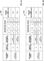
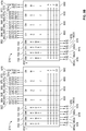
- FIGS. 4A-4B illustrate example charts 400 and 450, respectively, that illustrate how the multi-layered diversity strategy implemented within MPS 200 mitigates software- or software-logic based common-cause failures.
- Charts 400 and 450 illustrate how a multi-layered diversity strategy implemented within MPS 200 can eliminate a concern for software-based or software logic-based CCF within the MPS (e.g., MPS 200).
- the transient event is a loss of feedwater for a nuclear power system.
- two different process parameters, A1 and A2 are measured (e.g., through sensors 202a-202d).
- A1 as illustrated, is a temperature parameter while A2, as illustrated, is a pressure.
- an output of the safety function for A1 that indicates that protective action needs to be taken by all four separation groups (A, B, C, D) results in an initiation of protective action (e.g., as shown by the "Trip").
- FIG. 4B if there is a CCF in two separation groups (A and C), even two groups in a single division, for safety function A1, positive indications of a protective action in the other separation groups (B and D) still provide for sufficient votes (in a two-out-of-four scheme as described above) to initiate the protective action.
- the CCFs in groups A and C for safety function A1 do not propagate to safety function A2 because of the independent evaluation on each SFM.
- the output blocks 720 include, as illustrated, up to three independent output switches, or more in some examples, that can be used in external circuits and are coupled to electrical loads 702 (e.g., actuators). In some aspects, this allows for the EIM 700 to control a single component directly or provide an initiation signal for multiple components. For example, an output block 720 energizes a relay that starts various pumps and opens multiple valves. Each output block 720 may also include the capability to self-test and perform load continuity checks.
- the voting engine 722 receives the trip determination inputs from the communications blocks 724.
- the result of the voting provides an actuation or no actuation signal to the priority logic block 721 for an automatic actuation signal.
- the voting engine 722 may implement a voting scheme, and in some cases, a double voting scheme, to ensure that failures of a single component within the MPS do not propagate.
- the voting engine 722 receives trip determinations at the communications blocks 724.
- Each communication block 724 may receive a trip determination (e.g., trip or no trip) from four channels or separation groups (e.g., channels A-D described above).
- FIGS. 9A-9C illustrate block diagrams of separation group-, RTS-, and ESAFAS-level interconnects that utilize one or more of the SFM 500, CM 600, and EIM 700.
- the modules SFM 500, CM 600, and EIM 700 may be arranged within the MPS 200, for example, as functionally independent modules (e.g., an assembly of interconnected components that constitutes an identifiable device, instrument, or piece of equipment, and can be disconnected, removed as a unit, and replaced with a spare, with definable performance characteristics that permit it to be tested as a unit) that provide for protection against a single failure (e.g., hardware, software, or otherwise) from propagating to adjacent or other safety functions.
- a single failure e.g., hardware, software, or otherwise
- FIG. 10 illustrates a diversity analysis diagram for an I&C system 135 for a nuclear power system.
- the blocks identified in FIG. 10 represent a level of detail that simplifies system examination. Blocks have been selected to represent a physical subset of equipment and software whose internal failures can be assumed not to propagate to other blocks based on their attributes.
- blocks in the diagram of FIG. 10 illustrate an I&C system; in this example, I&C system 135.
- Block 1002 represents the non-IE monitoring and indication equipment
- block 1004a/b represent IE monitoring and indication I and II, respectively
- blocks 1006a/b represent Safety Blocks I and II, respectively.
- Block 1006a includes Separation Groups A and C, RTS I, and ESFAS I
- block 1006b includes Separation Groups B and D, RTS II, and ESFAS II.
- Block 1008 represents the MCS.
- connection lines with arrows indicate communication between blocks.
- Safety Block I and IE M/I I may be designed by one design team, with Safety Block II and IE M/l II may be designed by a different design team. Additionally, independent verification and validation teams may review the work of each design team to ensure design correctness. The above mentioned design teams are also different from those assigned to the Module Control System (MCS) and the non-IE M/I.
- MCS Module Control System
- the 1E M/I blocks involve a combination of video display units (digital hardware) and manual controls (non-digital hardware).
- the VDUs may be designed for indication only and do not have the capability to control equipment.
- the manual controls in each IE M/I block 1004a/b provide the operator the ability to initiate, at the division level, any protective action that is automatically performed by Safety Block I or II.
- a CCF can be assumed to affect one or the other, but not both.
Landscapes
- Engineering & Computer Science (AREA)
- Physics & Mathematics (AREA)
- General Engineering & Computer Science (AREA)
- Plasma & Fusion (AREA)
- High Energy & Nuclear Physics (AREA)
- Business, Economics & Management (AREA)
- Emergency Management (AREA)
- Automation & Control Theory (AREA)
- General Physics & Mathematics (AREA)
- Chemical & Material Sciences (AREA)
- Chemical Kinetics & Catalysis (AREA)
- Monitoring And Testing Of Nuclear Reactors (AREA)
- Testing And Monitoring For Control Systems (AREA)
- Safety Devices In Control Systems (AREA)
Description
- This application claims priority to
U.S. Provisional Patent Application Serial No. 61/922,625, filed December 31, 2013 U.S. Patent Application Serial No. 14/198,891, filed March 6, 2014 - This disclosure describes a nuclear reactor protection system and associated methods thereof.
- Nuclear reactor protection systems and, generally, nuclear reactor instrumentation and control (I&C) systems provide automatic initiating signals, automatic and manual control signals, and monitoring displays to mitigate the consequences of fault conditions. For example, I&C systems provide protection against unsafe reactor operation during steady state and transient power operation. During normal operation I&C systems measure various parameters and transmit the signals to control systems. During abnormal operation and accident conditions, the I&C systems transmit signals to the reactor protection system and, in some cases a reactor trip system (RTS) and engineered safety features actuation system (ESFAS) of the reactor protection system, to initiate protective actions based on predetermined set points.
-
US 6,532,550 B1 discloses a protection system for a complex process, in particular a nuclear reactor. The system has four redundant protection sets, each of which produces partial reactor trip and partial safeguard actuation signals. Two independent and redundant voting logic trains are provided for the partial reactor trip signals, and two identical, independent and redundant voting logic trains are provided for the partial safeguard actuation signals. Each of the trains includes a pair of redundant microprocessor-based voting logic controllers, each of which receives the partial reactor trip or partial safeguard actuation signals from each of the process protection sets and has a voting processor which generates an intermediate reactor trip or intermediate safeguard actuation signal in response to partial signals from a predetermined number of protection sets. The voting processors in the voting logic controllers apply a predetermined 2/4, 2/3 or 1/2 voting logic as appropriate to generate the intermediate reactor trip or safeguard actuation signals. The intermediate signals from the two voting logic controllers in each train are ANDed to generate train signals. The reactor trip train signals are then ORed to generate a reactor trip signal. Each of the train safeguard actuation signals activates a separate set of redundant components. -
US 2011/0313580 A1 discloses techniques for controlling plant operations. Various voting schemes - such as a 2/4 voting scheme, a 2/3 voting scheme, and a generic M/N voting scheme - are exemplified. The outputs of a plurality of voting results may be combined by a logic OR operation. - The present invention is defined by the independent claims. The dependent claims concern optional elements of some embodiments of the present invention.
- In a general implementation according to the present disclosure, a nuclear reactor protection system includes a plurality of functionally independent modules, each of the modules configured to receive a plurality of inputs from a nuclear reactor safety system, and logically determine a safety action based at least in part on the plurality of inputs; and one or more nuclear reactor safety actuators communicably coupled to the plurality of functionally independent modules to receive the safety action determination based at least in part on the plurality of inputs.
- In a first aspect combinable with the general implementation, each of the plurality of functionally independent modules provides protection against a single failure propagation to any other of the plurality of functionally independent modules.
- In a second aspect combinable with any of the previous aspects, the nuclear reactor safety system includes an engineered safety features actuation system (ESFAS), and the plurality of functionally independent modules receive a plurality of ESFAS inputs and logically determine an ESFAS component actuation based at least in part on the ESFAS inputs.
- In a third aspect combinable with any of the previous aspects, the plurality of functionally independent modules provide for redundant ESFAS voting divisions.
- In a fourth aspect combinable with any of the previous aspects, the nuclear reactor safety system includes a reactor trip system (RTS), and the plurality of functionally independent modules receive a plurality of RTS inputs and logically determine an RTS component actuation based at least in part on the RTS inputs.
- In a fifth aspect combinable with any of the previous aspects, the plurality of functionally independent modules provide for redundant RTS voting divisions.
- In a sixth aspect combinable with any of the previous aspects, each of the plurality of functionally independent modules provides protection against a single hardware failure propagation to any other of the plurality of functionally independent modules.
- In a seventh aspect combinable with any of the previous aspects, each of the plurality of functionally independent modules provides protection against a single software failure propagation to any other of the plurality of functionally independent modules.
- In an eighth aspect combinable with any of the previous aspects, each of the plurality of functionally independent modules provides protection against a single software developed logic failure propagation to any other of the plurality of functionally independent modules.
- In a ninth aspect combinable with any of the previous aspects, the plurality of functionally independent modules provides for triple redundancy for a signal path of a reactor trip sensing and determination.
- In a tenth aspect combinable with any of the previous aspects, the plurality of functionally independent modules provide include independent trip voting modules per reactor trip component.
- In an eleventh aspect combinable with any of the previous aspects, the plurality of functionally independent modules logically determine the reactor trip separately from every other module of the plurality of modules dedicated to the particular trip component.
- In a twelfth aspect combinable with any of the previous aspects, the plurality of functionally independent modules provide include independent ESFAS actuation voting modules per ESF component.
- In a thirteenth aspect combinable with any of the previous aspects, the plurality of functionally independent modules logically determine the ESFAS actuation separately from every other module of the plurality of modules dedicated to the particular ESF component.
- In a fourteenth aspect combinable with any of the previous aspects, the plurality of functionally independent modules include a plurality of safety function modules.
- In a second aspect combinable with any of the previous aspects, the plurality of functionally independent modules include a plurality of communication modules.
- In a fifteenth aspect combinable with any of the previous aspects, the plurality of functionally independent modules include a plurality of equipment interface modules.
- In a sixteenth aspect combinable with any of the previous aspects, the plurality of functionally independent modules logically determine the reactor trip in a single-tier voting scheme.
- In a seventeenth aspect combinable with any of the previous aspects, the plurality of functionally independent modules logically determine the reactor trip in a multiple-tier voting scheme.
- In an eighteenth aspect combinable with any of the previous aspects, the multiple-tier voting scheme includes a two-tier voting scheme.
- In a nineteenth aspect combinable with any of the previous aspects, a first tier of the two-tier voting scheme includes a majority voting scheme.
- In a twentieth aspect combinable with any of the previous aspects, the majority voting scheme includes a two out of three voting scheme.
- In a twenty-first aspect combinable with any of the previous aspects, a second tier of the two-tier voting scheme includes a non-majority vote scheme.
- In a twenty-second aspect combinable with any of the previous aspects, the second tier includes a two out of four vote scheme.
- In another general implementation according to the present disclosure, a method for determining a nuclear reactor trip includes receiving, from one of an engineered safety features actuation system (ESFAS) or a reactor trip system (RTS), a plurality of inputs at a plurality of functionally independent modules of a nuclear reactor protection system; logically determining, with the plurality of functionally independent modules, one of an ESFAS safety action or reactor trip determination, based at least in part on the plurality of inputs; and based on the logical determination, activating one of an ESFAS component actuator or a reactor trip breaker communicably coupled to the plurality of functionally independent modules.
- A first aspect combinable with the general implementation further includes limiting, with one of the plurality of functionally independent modules, a single failure propagation to any other of the plurality of functionally independent modules.
- In a second aspect combinable with any of the previous aspects, the single failure includes at least one of: a single hardware failure, a single software failure, or a single software developed logic failure.
- In a third aspect combinable with any of the previous aspects, logically determining, with the plurality of functionally independent modules, one of an ESFAS safety action or reactor trip determination, based at least in part on the inputs includes logically determining, with the plurality of functionally independent modules, the ESFAS safety action or reactor trip determination through a triple redundancy signal path.
- In a fourth aspect combinable with any of the previous aspects, the plurality of functionally independent modules provide for at least one of redundant RTS voting divisions or redundant ESFAS voting divisions.
- In a fifth aspect combinable with any of the previous aspects, logically determining, with the plurality of functionally independent modules, one of an ESFAS safety action or reactor trip determination, based at least in part on the inputs includes logically determining, with the plurality of functionally independent modules, the ESFAS safety action or reactor trip determination through independent trip voting modules per reactor trip component.
- In a sixth aspect combinable with any of the previous aspects, logically determining, with the plurality of functionally independent modules, one of an ESFAS safety action or reactor trip determination, based at least in part on the inputs includes logically determining, with a particular module of the plurality of functionally independent modules, the ESFAS safety action or reactor trip determination separately from every other module of the plurality of modules.
- In a seventh aspect combinable with any of the previous aspects, the plurality of functionally independent modules provide include independent ESFAS actuation voting modules per ESF component, the method further including logically determining, with a particular module of the plurality of functionally independent modules, the ESFAS actuation separately from every other module of the plurality of modules dedicated to the particular ESF component.
- In an eighth aspect combinable with any of the previous aspects, the plurality of functionally independent modules include a plurality of safety function modules, a plurality of communication modules, and a plurality of equipment interface modules.
- In a ninth aspect combinable with any of the previous aspects, logically determining, with the plurality of functionally independent modules, one of an ESFAS safety action or reactor trip determination, based at least in part on the inputs includes logically determining, with the plurality of functionally independent modules, the ESFAS safety action or reactor trip determination in a single-tier voting scheme.
- In a tenth aspect combinable with any of the previous aspects, logically determining, with the plurality of functionally independent modules, one of an ESFAS safety action or reactor trip determination, based at least in part on the inputs includes logically determining, with the plurality of functionally independent modules, the ESFAS safety action or reactor trip determination in a multiple-tier voting scheme.
- In an eleventh aspect combinable with any of the previous aspects, the multiple-tier voting scheme includes a two-tier voting scheme.
- In a twelfth aspect combinable with any of the previous aspects, a first tier of the two-tier voting scheme includes a majority voting scheme.
- In a thirteenth aspect combinable with any of the previous aspects, the majority voting scheme includes a two out of three voting scheme.
- In a fourteenth aspect combinable with any of the previous aspects, a second tier of the two-tier voting scheme includes a non-majority vote scheme.
- In a fifteenth aspect combinable with any of the previous aspects, the second tier includes a two out of four vote scheme.
- In another general implementation according to the present disclosure, a nuclear reactor protection system includes a plurality of functionally independent modules that limits migration of a single failure to a single module.
- In another general implementation according to the present disclosure, a nuclear reactor protection system includes a plurality of functionally independent modules that include by only three types of modules, thereby minimizing a number of line replaceable units.
- In another general implementation according to the present disclosure, a nuclear reactor protection system includes a plurality of functionally independent modules that include a communication module that determines a schedule of data passage through a data bus.
- In another general implementation according to the present disclosure, a nuclear reactor protection system includes a reactor trip system that defines a system architecture in which data is transmitted from the reactor trip system to a control room through a path that is exclusively associated with a safety function, rather than, for example, a post-accident monitoring function.
- In another general implementation according to the present disclosure, a nuclear reactor protection system includes a plurality of functionally independent modules, each of which is dedicated to a particular reactor trip breaker among a plurality of reactor trip breakers in the system.
- In another general implementation according to the present disclosure, a nuclear reactor protection system includes a plurality of functionally independent modules, each of which makes a reactor trip/no trip determination, or an ESFAS actuation/no actuation determination, completely independent of all of the other modules.
- In another general implementation according to the present disclosure, a nuclear reactor protection system includes a plurality of functionally independent modules, each of which is dedicated to a particular ESFAS equipment actuators among a plurality of ESFAS equipment actuators in the system.
- In another general implementation according to the present disclosure, a nuclear reactor protection apparatus includes means for receiving a plurality of inputs from a nuclear reactor safety system and logically determining a safety action based at least in part on the plurality of inputs; and means for receiving the safety action determination based at least in part on the plurality of inputs.
- In a first aspect combinable with the general implementation, the means for receiving the safety action determination is communicably coupled to the means for receiving the plurality of inputs from the nuclear reactor safety system and logically determining the safety action.
- In a second aspect combinable with any of the previous aspects, the means for receiving the plurality of inputs from the nuclear reactor safety system and logically determining the safety action provides protection against a single failure propagation within the apparatus.
- In a third aspect combinable with any of the previous aspects, the nuclear reactor safety system comprises an engineered safety features actuation system (ESFAS), and the means for receiving the plurality of inputs from the nuclear reactor safety system and logically determining the safety action receive a plurality of ESFAS inputs and logically determine an ESFAS component actuation based at least in part on the ESFAS inputs.
- In a fourth aspect combinable with any of the previous aspects, the means for receiving the plurality of inputs from the nuclear reactor safety system and logically determining the safety action provide for redundant ESFAS voting divisions.
- In a fifth aspect combinable with any of the previous aspects, the nuclear reactor safety system comprises a reactor trip system (RTS), and the means for receiving the plurality of inputs from the nuclear reactor safety system and logically determining the safety action receive a plurality of RTS inputs and logically determine an RTS component actuation based at least in part on the RTS inputs.
- In a sixth aspect combinable with any of the previous aspects, the means for receiving the plurality of inputs from the nuclear reactor safety system and logically determining the safety action comprise redundant RTS voting divisions.
- In a seventh aspect combinable with any of the previous aspects, the means for receiving the plurality of inputs from the nuclear reactor safety system and logically determining the safety action provides protection against a single hardware failure propagation within the apparatus.
- In an eighth aspect combinable with any of the previous aspects, the means for receiving the plurality of inputs from the nuclear reactor safety system and logically determining the safety action provides protection against a single software failure propagation within the apparatus.
- In a ninth aspect combinable with any of the previous aspects, the means for receiving the plurality of inputs from the nuclear reactor safety system and logically determining the safety action provides protection against a single software developed logic failure propagation within the apparatus.
- In a tenth aspect combinable with any of the previous aspects, the means for receiving the plurality of inputs from the nuclear reactor safety system and logically determining the safety action comprise a triple redundant signal path of a reactor trip sensing and determination.
- In an eleventh aspect combinable with any of the previous aspects, the means for receiving the plurality of inputs from the nuclear reactor safety system and logically determining the safety action comprise independent trip voting modules per reactor trip component.
- In a twelfth aspect combinable with any of the previous aspects, the means for receiving the plurality of inputs from the nuclear reactor safety system and logically determining the safety action independently determine a reactor trip for a particular reactor trip component.
- In a thirteenth aspect combinable with any of the previous aspects, wherein the means for receiving the plurality of inputs from the nuclear reactor safety system and logically determining the safety action comprise independent ESFAS actuation voting modules per ESF component.
- In a fourteenth aspect combinable with any of the previous aspects, the means for receiving the plurality of inputs from the nuclear reactor safety system and logically determining the safety action independently determine the ESFAS actuation for a particular ESF component.
- In a fifteenth aspect combinable with any of the previous aspects, the means for receiving the plurality of inputs from the nuclear reactor safety system and logically determining the safety action comprise a plurality of safety function modules.
- In a sixteenth aspect combinable with any of the previous aspects, the means for receiving the plurality of inputs from the nuclear reactor safety system and logically determining the safety action comprise a plurality of communication modules.
- In a seventeenth aspect combinable with any of the previous aspects, the means for receiving the plurality of inputs from the nuclear reactor safety system and logically determining the safety action comprise a plurality of equipment interface modules.
- In an eighteenth aspect combinable with any of the previous aspects, the means for receiving the plurality of inputs from the nuclear reactor safety system and logically determining the safety action logically determine a reactor trip in a single-tier voting scheme.
- In a nineteenth aspect combinable with any of the previous aspects, the means for receiving the plurality of inputs from the nuclear reactor safety system and logically determining the safety action logically determine a reactor trip in a multiple-tier voting scheme.
- In a twentieth aspect combinable with any of the previous aspects, the multiple-tier voting scheme comprises a two-tier voting scheme.
- In a twenty-first aspect combinable with any of the previous aspects, a first tier of the two-tier voting scheme comprises a majority voting scheme.
- In a twenty-second aspect combinable with any of the previous aspects, the majority voting scheme comprises a two out of three voting scheme.
- In a twenty-third aspect combinable with any of the previous aspects, a second tier of the two-tier voting scheme comprises a non-majority vote scheme.
- In a twenty-fourth aspect combinable with any of the previous aspects, the second tier comprises a two out of four vote scheme.
- Various implementations of a nuclear reactor protection system according to the present disclosure may include one, some, or all of the following features. For example, the reactor protection system may mitigate common-cause failures (CCF) caused by software or software-developed logic errors that could defeat and/or disable a safety function in the system. As another example, the reactor protection system may incorporate key attributes including independence, redundancy, determinism, multi-layered diversity, testability, and diagnostics. The reactor protection system may ensure that the nuclear reactor is maintained in a safe condition. As another example, the reactor protection system may have increased simplicity through a symmetrical architecture with the functionality implemented in individual logic engines dedicated to a particular function. As yet another example, the reactor protection system may facilitate communications within the architecture based on simple deterministic protocols and communicated via redundant paths.
- The details of one or more implementations of the subject matter described in this specification are set forth in the accompanying drawings and the description below. Other features, aspects, and advantages of the subject matter will become apparent from the description, the drawings, and the claims.
-
-
FIG. 1 illustrates a block diagram of an example implementation of a system that includes multiple nuclear power systems and an instrumentation & control (I&C) system; -
FIGS. 2A-2B illustrate a block diagram of module protection system (MPS) of an I&C system for a nuclear power system; -
FIG. 3A illustrates a block diagram of a trip determination block of an MPS of an I&C system for a nuclear power system; -
FIG. 3B illustrates a block diagram of an engineered safety features actuation system (ESFAS) of an MPS of an I&C system for a nuclear power system; -
FIGS. 4A-4B illustrate example charts that illustrate a multi-layered diversity strategy that mitigates software- or software-logic based common-cause failures within an MPS ensuring the I&C system can perform its intended safety function(s); -
FIG. 5 illustrates a block diagram of a safety function module (SFM) of an MPS of an I&C system for a nuclear power system; -
FIG. 6 illustrates a block diagram of a communications module (CM) of an MPS of an I&C system for a nuclear power system; -
FIG. 7 illustrates a block diagram of an equipment interface module (EIM) of an MPS of an I&C system for a nuclear power system; -
FIG. 8 illustrates an example of a chassis of a reactor protection system that communicably couple one or more SFM, EIM, and CM; -
FIGS. 9A-9C illustrate block diagrams of trip determination-, RTS-, and ESFAS-level interconnects that utilize one or more of the SFM, CM, and EIM; -
FIG. 10 illustrates a diversity analysis diagram for an MPS of an I&C system for a nuclear power system; and -
FIG. 11 illustrates a block diagram of an example separation of MPS blocks into the four echelons of defense. -
FIG. 1 illustrates an example implementation of asystem 100 that includes multiplenuclear power systems 150 and a nuclear instrumentation and control (I&C)system 135. Generally, theI&C system 135 provides automatic initiating signals, automatic and manual control signals, and monitoring and indication displays to prevent or mitigate the consequences of fault conditions in thesystem 100. TheI&C system 135 provides normal reactor controls and protection against unsafe reactor operation of thenuclear power systems 150 during steady state and transient power operation. During normal operation, instrumentation measures various process parameters and transmits the signals to the control systems ofI&C system 135. During abnormal operation and accident conditions, the instrumentation transmits signals to portions of the I&C system 135 (e.g., a reactor trip system (RTS) 147 and engineered safety features actuation system (ESFAS) 148 (e.g., for mitigating the effects of an accident) that are part of a module protection system (MPS) 145) to initiate protective actions based on predetermined set points. - In
FIG. 1 , thesystem 100 includes multiplenuclear power systems 150 that are electrically coupled toI&C system 135. Although only threenuclear power systems 150 are shown in this example, there may be fewer ormore systems 150 that are included within or coupled to the system 100 (e.g., 6, 9, 12, or otherwise). In one preferred implementation, there may be twelvenuclear power systems 150 included withinsystem 100, with one or more of thenuclear power systems 150 including a modular, light-water reactor as further described below. - With respect to each
nuclear power system 150 and although not shown explicitly, a nuclear reactor core may provide heat, which is utilized to boil water either in a primary coolant loop (e.g., as in a boiling water reactor) or in a secondary cooling loop (e.g., as in a pressurized water reactor). Vaporized coolant, such as steam, may be used to drive one or more turbines that convert the thermal potential energy into electrical energy. After condensing, coolant is then returned to again remove more heat energy from the nuclear reactor core.Nuclear power system 150 is one example of any system which requires monitoring and protection functions in order to minimize the hazards associated with failures within the system. - In a specific example implementation of each
nuclear reactor system 150, a reactor core is positioned at a bottom portion of a cylinder-shaped or capsule-shaped reactor vessel. Reactor core includes a quantity of fissile material that produces a controlled reaction that may occur over a period of perhaps several years or longer. Although not shown explicitly inFIG. 1 , control rods may be employed to control the rate of fission within reactor core. Control rods may include silver, indium, cadmium, boron, cobalt, hafnium, dysprosium, gadolinium, samarium, erbium, and europium, or their alloys and compounds. However, these are merely a few of many possible control rod materials. In nuclear reactors designed with passive operating systems, the laws of physics are employed to ensure that safe operation of the nuclear reactor is maintained during normal operation or even in an emergency condition without operator intervention or supervision, at least for some predefined period of time. - In implementations, a cylinder-shaped or capsule-shaped containment vessel surrounds reactor vessel and is partially or completely submerged in a reactor pool, such as below a waterline, within a reactor bay. The volume between reactor vessel and containment vessel may be partially or completely evacuated to reduce heat transfer from reactor vessel to the reactor pool. However, in other implementations, the volume between reactor vessel and containment vessel may be at least partially filled with a gas and/or a liquid that increases heat transfer between the reactor and containment vessels. Containment vessel may rest on a skirt at the base of reactor bay.
- In a particular implementation, reactor core is submerged within a liquid, such as water, which may include boron or other additive, which rises into channel after making contact with a surface of the reactor core. The coolant travels over the top of heat exchangers and is drawn downward by way of convection along the inner walls of reactor vessel thus allowing the coolant to impart heat to heat exchangers. After reaching a bottom portion of the reactor vessel, contact with reactor core results in heating the coolant, which again rises through channel.
- Heat exchangers within the reactor vessel may represent any number of helical coils that wrap around at least a portion of the channel. In another implementation, a different number of helical coils may wrap around channel in an opposite direction, in which, for example, a first helical coil wraps helically in a counterclockwise direction, while a second helical coil wraps helically in a clockwise direction. However, nothing prevents the use of differently-configured and/or differently-oriented heat exchangers and implementations are not limited in this regard.
- In
FIG. 1 , normal operation of the nuclear reactor module proceeds in a manner wherein heated coolant rises through the channel and makes contact with heat exchangers. After contacting heat exchangers, the coolant sinks towards the bottom of the reactor vessel in a manner that induces a thermal siphoning process. In the example ofFIG. 1 , coolant within the reactor vessel remains at a pressure above atmospheric pressure, thus allowing the coolant to maintain a high temperature without vaporizing (e.g., boiling). - As coolant within heat exchangers increases in temperature, the coolant may begin to boil. As the coolant within heat exchangers begins to boil, vaporized coolant, such as steam, may be used to drive one or more turbines that convert the thermal potential energy of steam into electrical energy. After condensing, coolant is returned to locations near the base of the heat exchangers.
- During normal operation of the
nuclear power system 150 ofFIG. 1 , various performance parameters of the nuclear power system may be monitored by way of sensors, e.g., of theI&C system 135, positioned at various locations within thenuclear power system 150. Sensors within the nuclear power system may measure system temperatures, system pressures, primary and/or secondary coolant levels, and neutron flux. Signals that represent these measurements may be reported external to the nuclear power system by way of communication channels to an interface panel of theI&C system 135. - The illustrated
I&C system 135, generally, includes amain control room 140, a module (or reactor) protection system (MPS) 145, and a non-safety module control system (MCS) 155. Themain control room 140 includes a set of controls andindicators 141 for eachnuclear power system 150. Each set of controls andindicators 141 includes manual IE controls 142, IE indicators 143, and non IE controls andindicators 144. In some aspects, "IE," may refer to regulatory requirements such as those that define a IE scheme under IEEE Std. 308-2001, section 3.7, endorsed by Nuclear Regulatory Commission Regulatory Guide 1.32, which defines a safety classification of the electric equipment and systems that are essential to emergency reactor shutdown, containment isolation, reactor core cooling, and containment and reactor heat removal, or that are otherwise essential in preventing significant release of radioactive material into the environment. Typically, certain controls and indicators may be "IE" qualified (e.g., the manual IE controls 142 and IE indicators 143) while other controls and indicators may not be "IE" qualified (e.g., the non-IE controls and indicators 144). - The non-1E controls and
indicators 144 is in bi-directional communication with theMCS 155. TheMCS 155 may provide control and monitoring of the non-safety portions of thenuclear power system 150. Generally, theMCS 155 constrains operational transients, to prevent unit trip, and re-establish steady state unit operation, among other operations. - The
MPS 145 is in one-way communication each with the manual IE controls 142 and the IE indicators 143 as shown inFIG. 1 . TheMPS 145, generally, initiates safety actions to mitigate consequences of design basis events. TheMPS 145, generally, includes all equipment (including hardware, software, and firmware) from sensors to the final actuation devices (power sources, sensors, signal conditioners, initiation circuits, logic, bypasses, control boards, interconnections, and actuation devices) required to initiate reactor shutdown. - The
MPS 145 includes theRTS 147 and theESFAS 148. TheRTS 147, in some aspects, includes four independent separation groups (e.g., a physical grouping of process channels with the same Class-IE electrical channel designation (A, B, C, or D)), which is provided with separate and independent power feeds and process instrumentation transmitters, and each of which groups is physically and electrically independent of the other groups) with independent measurement channels to monitor plant parameters that can be utilized to generate a reactor trip. Each measurement channel trips when the parameter exceeds a predetermined set point. The coincident logic of theRTS 147 may be designed so that no single failure can prevent a reactor trip when required, and no failure in a single measurement channel can generate an unnecessary reactor trip. - The
ESFAS 148, in some aspects, includes four independent separation groups with independent measurement channels, which monitor plant parameters, that can be utilized to activate the operation of the engineered safety features (ESF) equipment. Each measurement channel trips when the parameter exceeds a predetermined set point. TheESFAS 148's coincident logic may be designed so that no single failure can prevent a safeguards actuation when required, and no single failure in a single measurement channel can generate an unnecessary safeguards actuation. -
System 100 may include four echelons of defense, e.g., specific applications of the principle of defense-in-depth to the arrangement of instrumentation and control systems attached to a nuclear reactor for the purpose of operating the reactor or shutting it down and cooling it, as defined in NUREG/CR-6303. Specifically, the four echelons are a control system, a reactor trip or scram system, an ESFAS, and a monitoring and indicator system (e.g., the slowest and the most flexible echelon of defense that includes both Class IE and non-Class IE manual controls, monitors, and indicators required to operate equipment nominally assigned to the other three echelons). - The control system echelon, typically, includes MCS 155 (e.g., non-Class IE manual or automatic control equipment), which routinely prevents reactor excursions toward unsafe regimes of operation and is generally used to operate the reactor in the safe power production operating region. Indicators, annunciators, and alarms may be included in the control echelon. Reactor control systems typically contain some equipment to satisfy particular rules and/or requirements, e.g., the requirement for a remote shutdown panel. The reactor control functions performed by the control system echelon are included in the
MCS 155. TheMCS 155, for instance, includes functions to maintain thesystem 100 within operating limits to avoid the need for reactor trip or ESF actuation. - The reactor trip system echelon, typically, includes the
RTS 147, e.g., safety equipment designed to reduce reactor core reactivity rapidly in response to an uncontrolled excursion. This echelon typically consists of instrumentation for detecting potential or actual excursions, equipment and processes for rapidly and completely inserting the reactor control rods, and may also include certain chemical neutron moderation systems (e.g., boron injection). As illustrated, automatic reactor trip functions performed by the reactor trip echelon are included in the MPS 145 (e.g., in the RTS 147). - The ESFAS echelon, typically, includes the
ESFAS module 148 that is part of theMPS 145. The ESFAS echelon, as implemented in theESFAS module 148, typically includes safety equipment which removes heat or otherwise assists in maintaining the integrity of the three physical barriers to radioactive material release (e.g., nuclear fuel rod cladding, reactor vessel, and reactor containment). This echelon detects the need for and performs such functions as emergency reactor cooling, pressure relief or depressurization, isolation, and control of various support systems (e.g., emergency generators) or devices (valves, motors, pumps) required for ESF equipment to operate. - The monitoring and indicator system echelon, typically, includes the
main control room 140, and, in some aspects, is the slowest and also the most flexible echelon of defense. Like the other three echelons, human operators (e.g., of system 100) are dependent upon accurate sensor information to perform their tasks, but, given information, time, and means, can perform previously unspecified logical computations to react to unexpected events. The monitoring and indication echelon includes Class IE and non-Class IE manual controls, monitors, and indicators required to operate equipment nominally assigned to the other three echelons (e.g., through the manual 1E controls 142, 1E indicators 143, and non-IE controls and indicators 144). The functions required by the monitoring and indicator system echelons are provided by the manual controls, displays, and indicators in the main control room, which includes information from theMCS 155 andMPS 145. The safety monitoring, manual reactor trip, and manual ESF actuation functions are included in theMPS 145. TheMCS 155 provides non-safety monitoring and manual controls to maintain operating limits during normal plant operation. - In addition to including the four echelons of defense,
system 100 includes multiple levels of diversity. Specifically, I&C diversity is a principle of measuring variables or providing actuation means, using different technology, logic or algorithms, to provide diverse ways of responding to postulated plant conditions. Here, diversity is applied to the principle in instrumentation systems of sensing different parameters, using different technologies, logic or algorithms, or means of actuation to provide several ways of detecting and responding to a significant event. Diversity is complementary to the principle of defense-in-depth and increases the chances that defenses at a particular level or depth will be actuated when needed. Generally, there are six attributes of diversity: human diversity, design diversity, software diversity, functional diversity, signal diversity, and equipment diversity. As discussed in more depth in the present disclosure, theMPS 145 may incorporate the six attributes of diversity in order to mitigate the effects of a common-cause failure (e.g., a failure caused by software errors or software-developed logic that could defeat the redundancy achieved by hardware architecture) in theMPS 145. - Generally, human diversity relates to addressing human-induced faults throughout the system development life-cycle (e.g., mistakes, misinterpretations, errors, configuration failures) and is characterized by dissimilarity in the execution of life-cycle processes.
- Generally, design diversity is the use of different approaches, including software and hardware, to solve the same or a similar problem. Software diversity is a special case of design diversity and is mentioned separately because of its potential importance and its potential defects. The rationale for design diversity is that different designs have different failure modes and are not be susceptible to the same common influences.
- Generally, software diversity is the use of different software programs designed and implemented by different software development groups with different key personnel to accomplish the same safety goals, for example, using two separately designed programs to determine when a reactor should be tripped.
- Generally, functional diversity refers to two systems (e.g., sub-systems within system 100) that perform different physical or logical functions though they may have overlapping safety effects.
- Generally, signal diversity is the use of different process parameters to initiate protective action, in which any of the parameters may independently indicate an abnormal condition, even if the other parameters fail to be detected correctly.
- Generally, equipment diversity is the use of different equipment to perform similar safety functions (e.g., one of the processes or conditions essential to maintain plant parameters within acceptable limits established for a design basis event, which may be achieved by the RTS or the ESF completing all required protective actions or the auxiliary supporting features completing all required protective actions, or both). In this case, "different" may mean sufficiently unlike as to significantly decrease vulnerability to common cause failure.
- In some aspects, the
MPS 145 may incorporate a combination of continuous (or partially continuous) self-testing and periodic surveillance testing. Such a test strategy may ensure that all detectable failures are identified and announced to the station personnel (e.g., through the main control room 140). Self-test features may provide a comprehensive diagnostic system ensuring that a system status is continually (or partially) monitored. All detectable failures may be announced to station personnel, and an indication of the impact of the failure may be provided to determine the overall status of the system. The self-test features maintain separation group and division independence. The self-test features ensure system integrity is maintained at all times. - In some aspects, each sub module within the MPS 145 (described in more detail below) may contain self-test features providing high fault detection coverage designed to detect single failures within the module. This may minimize the time required to detect faults, providing a benefit to safety and system availability. While the system is in normal operation, the self-tests run without affecting the performance of the safety function, such as response time.
- The self-test features may be capable of detecting most faults in both active and inactive logic (e.g., logic that is activated only when a safety function is required to operate) to avoid having an undetected fault. Fault detection and indication occurs at the MPS sub module level, enabling plant personnel to easily identify the MPS sub module that needs to be replaced.
- Periodic on-line surveillance testing capability may be incorporated to ensure all functional tests and checks, calibration verification, and time response measurements are validated. The periodic surveillance testing also verifies the continual self-testing functions.
- The self-test and periodic surveillance testing features in the
MPS 145 may be designed for in-service testability commensurate with the safety functions to be performed for all plant operating modes. The performance self-testing and surveillance testing does not require any makeshift test setups. The testing features may be inherent to the design of the system and add minimal complexity to the safety function logic and data structures. Continual indication of a bypass condition is made if: (1) a fault is detected by self-testing during normal operation of the plant, or (2) some part of a safety function is bypassed or deliberately rendered inoperable for testing. Once the bypass condition is removed, the indication of the bypass is removed. This may ensure that plant personnel can confirm that a bypassed safety function has been properly returned to service. - Diagnostics data for the
MPS 145 are provided to a maintenance workstation (MWS) for each separation group and division. The MWS may be located close to the equipment to facilitate troubleshooting activities. The interface between the MPS and the MWS may be an optically-isolated, one-way diagnostic interface. All diagnostics data may be communicated via a physically separate communications path, ensuring that diagnostics functionality is independent of safety functionality. Additionally, the diagnostics data may be transmitted to a central historian for long-term storage. This provides a means of performing an historical analysis of the system operation. - The diagnostic system may maintain a list of installed modules. The lists may be continually compared to the installed modules that are active in the system to guard against a missing module or an incorrect module being installed.
- All MPS safety data communications may be designed with error detection to enhance data integrity. The protocol features ensure communications are robust and reliable with the ability to detect transmission faults. Similar data integrity features may be used to transfer diagnostics data.
-
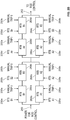
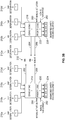
FIGS. 2A-2B illustrate a block diagram of module protection system (MPS) 200 of an I&C system for anuclear power system 150. In some implementations, theMPS 200 may be similar or identical to theMPS 145 shown inFIG. 1 . Generally, the illustratedMPS 200 includes four separation groups of sensors and detectors (e.g.,sensors 202a-202d); four separation groups of signal conditioning and signal conditioners (e.g.,signal conditioners 204a-204d); four separation groups of trip determination (e.g.,trip determinations 208a-208d); two divisions of RTS voting and reactor trip breakers (e.g., division I RTS voting 214, and division II RTS voting 216); and two divisions of engineered safety features actuation system (ESFAS) voting and engineered safety features (ESF) equipment (e.g., division I ESFAS voting 212 andESF equipment 224, and division II ESFAS voting 218 and ESF equipment 226). - Generally, the
sensors 202a-202d include process sensors that are responsible for measuring different process parameters such as pressure, temperature, level, and neutron flux. Thus, each process parameter of thenuclear power system 150 is measured using different sensors, and is processed by different algorithms, which are executed by different logic engines.
In some aspects, neutron flux sensors are responsible for measuring neutron flux from a reactor core from a shutdown condition up to 120 percent of full power. Three types of neutron flux detectors may be used in theMPS 200, including source range, intermediate range, and power range - Generally, the
signal conditioners 204a-204d receive the measurements from thesensors 202a-202d, process the measurements and provideoutputs 206a-206d. In some aspects, the interconnections of thesensors 202a-202d to thesignal conditioners 204a-204d may be dedicated copper wires or some other signal transmission method. - The
signal conditioners 204a-204d each may be comprised ofmultiple input modules 270a-270n (e.g., indicating any number of modules depending on the number of sensor inputs), as shown inFIG 3A , that are responsible for conditioning, measuring, filtering, and sampling field inputs from thesensors 202a-202d. Eachinput module 270a-270n may be dedicated to a specific input type, such as 24 V or 48 V digital inputs, 4-20 mA analog inputs, 0-10 V analog inputs, resistance thermal detector inputs, or thermo-couple inputs. - Each
input module 270a-270n may be comprised of an analog circuit and a digital circuit. The analog circuit is responsible for converting analog voltages or currents into a digital representation. It is also referred to as signal conditioning circuitry. The digital portion of eachinput module 270a-270n may be located within a logic engine. The logic engine performs all input module control, sample and hold filtering, integrity checks, self-testing, and digital filtering functions. The digital representation of the sensor output is communicated from thesignal conditioners 204a-204d to thetrip determination 208a-208d through theoutputs 206a-206d using, in some examples, a serial interface. - With reference to
FIG. 3A as well, thetrip determinations 208a-208d, generally, receive sensor input values in a digital format via a serial interface from thesignal conditioners 204a-204d as described above. Thetrip determinations 208a-208d are each comprised of independent safety function modules (SFM) 272a-272n (described more fully with reference toFIG. 5 ), where a specific module implements one set of safety functions (e.g., a set may be a single safety function or multiple safety functions related to a particular process parameter). For example, a set of safety functions may consist of a group of functions related to a primary variable, such as a high and low trip from the same pressure input. EachSFM 272a-272n contains a unique logic engine dedicated to implementing one set of safety functions. This results in a gate level implementation of each set of safety functions being entirely different from all other sets of safety functions. - The sensor input values (e.g.,
outputs 206a-206d) may be communicated via a deterministic path and are provided to aspecific SFM 272a-272n in eachtrip determination 208a-208d. These input values may then be converted to engineering units to determine what safety function, or a set of safety functions, is implemented on thatspecific SFM 272a-272n. Thetrip determinations 208a-208d provide these engineering unit values to the control system via, in some examples, an isolated, transmit only, fiber optic connection. - The SFMs in each
trip determination 208a-208d make a reactor trip determination based, if required, on a predetermined set point, and provides a trip or no-trip demand signal to each RTS division (e.g., theRTS voting ESFAS voting - As shown in
FIGS. 3A-3B , for instance, aparticular trip determination 208a provides a trip or no-trip demand signal to ESFAS voting 212 throughoutput 274a and to ESFAS voting 218 throughoutput 274b. Thetrip determination 208a provides a trip or no-trip demand signal to RTS voting 214 throughoutput 276a and to RTS voting 216 throughoutput 276b. These outputs are also generally shown inFIG. 2A asoutputs 210a-210d from thetrip determinations 208a-208d, respectively. - As further shown in
FIG. 3A , for instance, aparticular trip determination 208a provides a trip or no-trip demand signal to monitoring & indication (M&I) outputs 278a and 278b (one per division), as well as to anon-IE output 280.Outputs Output 280 provides process information and trip status information to the non-IE controls andindicators 144. - Returning to
FIG 2A , each RTS division (e.g., RTS voting 214 for division I and RTS voting 216 for division II) receives inputs from thetrip determinations 208a-208d as described above via isolated, and in some aspects redundant (e.g., double, triple, or otherwise), receive only,serial connections 210a-210d. The trip inputs are combined in the RTS voting logic so that two or more reactor trip inputs from thetrip determinations 208a-208d produce an automatic reactor trip output signal onoutputs 228a-228d and 230a-230d (as appropriate for each division) that actuates the trip coils for four of the eight reactor trip breakers (RTB) (shown inFIG. 2B ) associated with the respective division. In other words, the RTS voting logic, in this example implementation of theMPS 200, work on a "2 out of 4" logic, meaning that if at least two of the fourtrip determinations 208a-208d indicate that a reactor "trip" is necessary, then a trip signal is sent to the each of theRTB 264a - 264d and 266a - 266d. This breaker configuration permits safe and simple on-line testing of theMPS 200. - A
manual trip 250a provides a direct trip of the RTB 266a-266d (for division I) andmanual trip 250b provides a direct trip of theRTB 264a-264d (for division II) as well as input to the automatic actuation, manual trip 234 (for division I) and manual trip 236 (for division II) to ensure the sequence is maintained. - As further illustrated, each
RTB 264a-264d and each RTB 266a-266d includes, as an input, amanual trip manual trips power input 260 will not be transmitted topower output 262 regardless of the status (e.g., trip or no-trip) of theinputs 230a-230d andinputs 228a-228d). - ESFAS voting and logic are arranged, in the example implementation, so that no single failure can prevent a safeguards actuation when required, and no single failure in a trip determination signal (e.g., 210a-210d) can generate an unnecessary safeguards actuation. The ESFAS system may provide both automatic and manual initiation of critical systems, such as the emergency core cooling system and the decay heat removal system.
- Each ESFAS voting 212/218 receives
inputs 210a-210d from thetrip determinations 208a-208d via isolated, triple-redundant, receipt only, fiber optic (or other communication technique) connections. Actuation logic and voting occur within the ESFAS voting 212/218. When the ESFAS voting 212/218 determine an actuation is required, the ESFAS voting 212/218 sends an actuation demand signal toESFAS priority logic 220/222, respectively, which actuatesappropriate ESF equipment - The illustrated implementation of the
MPS 200 inFIGS. 2A-2B and3A-3B ensures a high level of independence between the key elements. This includes independence between the four separation groups of sensors anddetectors 202a-202d, the four separation groups of trip determination (labeled "a" through "d"), the two divisions ofRTS 214/216 (division I and division II as described), the two divisions of theESFAS circuitry 212/218 (division I and division II as described), and the two divisions of theESF equipment 224/226 (division I and division II as described). Based on inputs to an SFM (e.g., in thetrip determinations 208a-208d), theMPS 200 implements a set of safety functions independently within each of the four separation groups. Safety function independence is maintained from thesensors 202a-202d to thetrip determination output 210a-210d. This configuration, in some aspects, limits SFM failures to those based on that module's inputs. This strategy may help limit the effects of a common-cause failure and enhance signal diversity. This method of independence may also ensure a failure within independent safety functions does not propagate to any of the other safety functions modules. Further, on-line replacement of a failed SFM ensures that the failure can be corrected with minimal, if any, impact to other modules. - Communication of safety function data within the illustrated
MPS 200 is transmitted or received via triple module, redundant, independent, optically isolated, one-way communication paths. This communication scheme may ensure that, apart from interdivisional voting, a safety function is not dependent on any information or resource originating outside its division to accomplish its safety function. Fault propagation between Class IE divisions (e.g., divisions I and II) is prevented by one-way isolation (e.g., optical isolation or otherwise) of the divisional trip signals. - The illustrated implementation of the
MPS 200 inFIGS. 2A-2B and3A-3B further incorporates redundancy in multiple areas of the illustrated architecture. The redundancy within theMPS 200 includes four separation groups of sensors and detectors (labeled "a" through "d"), trip determination (labeled "a" through "d"), and two divisions of RTS and ESFAS circuitry (division I and division II as described). TheMPS 200 also uses two-out-of-four voting so that a single failure of an initiation signal will not prevent a reactor trip or ESF equipment actuation from occurring when required. Additionally, a single failure of an initiation signal will not cause spurious or inadvertent reactor trips or ESF equipment actuations when they are not required. - The
MPS 200 also incorporates functional independence by implementing each set of safety functions, which is used to mitigate a particular transient event on an independent SFM with a unique logic engine for that particular set of safety functions. - In some aspects, the
MPS 200 implements design techniques to realize a simple, highly reliable, and safe design for a nuclear reactor system. For example, theMPS 200 may be based on a symmetrical architecture of four separation groups and two divisions. Each of the four separation groups may be functionally equivalent to the others, and each of the two divisions may be functionally equivalent. As described above, two-out-of-four voting may be the only voting strategy in the illustrated implementation. As another example, logic of theMPS 200 may be implemented in finite-state machines (e.g., a collection of digital logic circuits that can be in one of a finite number of states, and is in only one state at a time, called the current state, but may change from one state to another when initiated by a triggering event or set of conditions, such as a state transition) dedicated to a particular safety function or group of safety functions. Thus, no kernel or operating system is required. As another example, communications within theMPS 200 may be based on deterministic protocols, and all safety data are communicated via redundant communication paths. As another example, diversity attributes of theMPS 200 may be designed to be inherent to the architecture without the additional complexities of additional systems based on completely different platforms. - For instance,
FIGS. 4A-4B illustrateexample charts MPS 200 mitigates software- or software-logic based common-cause failures.Charts MPS 200 can eliminate a concern for software-based or software logic-based CCF within the MPS (e.g., MPS 200). In these examples, the transient event is a loss of feedwater for a nuclear power system. As illustrated, two different process parameters, A1 and A2, are measured (e.g., throughsensors 202a-202d). A1, as illustrated, is a temperature parameter while A2, as illustrated, is a pressure. - The different process measurements, A1 and A2, are input into two different safety function algorithms: (A1) High Temperature and (A2) High Pressure, as illustrated. Each of the two safety function algorithms are located on an separate and independent SFM within a separation group. The safety function algorithms may be implemented using two different sets of programmable digital hardware (A/C and B/D) divided into four separation groups (A, B, C, D) and two divisions, as is shown with
MPS 200. For example, here, the two safety functions comprise a single set of safety functions. Each set (e.g., of two safety function algorithms) may be based on different technology. - Design diversity is also incorporated by process as each set of programmable digital hardware may be designed by different design teams using different sets of design tools. As one example, the safety function(s) may be implemented in a microprocessor. In this example, the safety function(s) may be evaluated in a sequential manner that, in some aspects, may introduce a dependency of one safety function (A2 for instance) on another safety function (A1 for instance) due to the sequential operation of the processing loop. As another example, the safety functions may be implemented in a state-based field programmable gate array (FPGA). In this example, each safety function may be evaluated independently of every other safety function. This latter example may ensure an increased independence by removing any dependence of the processing of one safety function on another safety function.
- The multi-layered diversity for the loss of feedwater transient event example provides protection against a CCF defeating the protective action by limiting the software CCF to one set (A/C) of a particular safety function (A1). In some aspects, the software CCF is limited to a particular safety function based on the functional independence between the two safety functions and the process measurements that the safety function algorithms use as inputs. In some aspects, the software CCF is limited to one set of a particular safety function by incorporating different programmable hardware, design teams, and design tools for each set. With the CCF limited to one set of a particular safety function, the transient event is mitigated by the other set (B/D) of that safety function (A1) or both sets (A/C and B/D) of the second safety function (A2).
- For example, as shown in
FIG. 4A , an output of the safety function for A1 that indicates that protective action needs to be taken by all four separation groups (A, B, C, D) (e.g., shown by the check marks) results in an initiation of protective action (e.g., as shown by the "Trip"). As shown inFIG. 4B , if there is a CCF in two separation groups (A and C), even two groups in a single division, for safety function A1, positive indications of a protective action in the other separation groups (B and D) still provide for sufficient votes (in a two-out-of-four scheme as described above) to initiate the protective action. Further, the CCFs in groups A and C for safety function A1 do not propagate to safety function A2 because of the independent evaluation on each SFM. -
FIG. 5 illustrates a block diagram of a safety function module (SFM) 500 of an MPS of an I&C system for a nuclear power system.FIG. 6 illustrates a block diagram of a communications module (CM) 600 of an MPS of an I&C system for a nuclear power system.FIG. 7 illustrates a block diagram of an equipment interface module (EIM) 700 of an MPS of an I&C system for a nuclear power system.FIG. 8 (discussed below) illustrates the communications paths within a chassis (e.g., a mechanical structure that interconnects one ormore SFM 500,CM 600, and EIM 700). Generally, the illustratedmodules chassis 800 and as described below), implement the safety functions of theMPS 200 and make up the separation group level modules (e.g.,signal conditioners 204a-204d,trip determinations 208a-208d), the RTS level modules (e.g., RTS voting 214/216), and the ESFAS level modules (e.g., ESFAS voting 212/218). In some aspects, having three types of modules (500, 600, and 700) may minimize the number of line replaceable units, thereby minimizing obsolescence. Further, these modules (500, 600, and 700) may be functionally independent so that a single failure in any individual module (500, 600, and 700) does not propagate to other modules or other safety functions. Further, the combinations of modules (500, 600, and 700) as implemented inFIGS. 8A-8C may provide for discrete, deterministic safety signal paths. - In some aspects, the modules (500, 600, and 700) may have one or more characteristics that defines, at least in part, their functional independence. For example, each of the modules may be fully autonomous relative to each other module in an overall system/architecture (e.g., in the MPS 200). As another example, each of the modules may perform a particular, intended safety function autonomously relative to each other module in the overall system/architecture. As yet another example, each of the modules may include dedicated logic, which is specific to the particular, intended safety function of the module. Each functionally independent module may not, therefore, be dependent on logic or functionality from any other module to complete the particular, intended safety function.
- Turning to
FIG. 5 , theSFM 500, as illustrated, processes sensor inputs or data from other SFMs to make reactor trip and/or ESF actuation determinations for the separation group to which the particular SFM is assigned (e.g., separation group A, B, C, or D). AnSFM 500 can be used in two separate configurations: (1) sensor signal conditioning with safety data bus communication, and reactor trip and/or ESF actuation; and (2) safety data bus communication with reactor trip determination and/or ESF actuation determination. - As illustrated, the
SFM 500 generally includes aninput block 504, afunctional logic block 512, and communication blocks 514, 516 and 518. Each input block 504 (four shown inFIG. 5 ) consists of asignal conditioning circuit 506, analog-to-digital (A/D)converter 508, andserial interface 510. Eachinput block 504 is communicably coupled to a sensor 502 (e.g., that may be the same or similar to thesensors 202a-202d). As shown, anindividual SFM 500 can handle up to four input blocks 504 (in the illustrated example). The input type can be any combination of analog and digital (e.g. 4-20 mA, 10-50 mA, 0-10 V) that theSFM 500 would need to make a trip or ESF actuation determination, including the generation of permissives and interlocks. - The
functional logic block 512 is a programmable portion of theSFM 500 that converts an output from theserial interface 510 of an input block 504 (if used) into engineering units. Thefunctional logic block 512 may also makes a trip and/or ESF actuation determination based on the output of the input block 504 (e.g., based on sensor measurement from sensor 502) and/or information from safety data buses. Thefunctional logic block 512 may also generate permissives and control interlocks. As illustrated, thefunctional logic block 512 consists of multiple deterministic logic engines that utilize the input blocks 504 and/or information obtained from safety data buses to make a trip or ESF actuation determination. - Setpoint and other tunable information utilized by the
functional logic block 512 may be stored in non-volatile memory (e.g., on the SFM 500). This may allow for changes without modifying underlying logic. Further, to implement functional, signal and software diversity, a primary and backup function used to mitigate an AOO or PA may not be on thesame SFM 500. Thus, by using adedicated SFM 500 for a function or group of functions and by ensuring primary and backup functions are onseparate modules 500, the effect of a software CCF is limited due to the unique logic and algorithm on eachmodule 500. - The communication blocks 514/516/518 consists of five separate communication ports (e.g., three safety data ports labeled 514, one port labeled 516, and one port labeled 518). Each port may be functionally independent and is designated as either a Monitoring and Indication (M/I) Bus (e.g., block 516), Maintenance Workstation (MWS) Bus (e.g., block 518), or a Safety Bus (e.g., blocks 514). Although each
safety data bus 514 may communicate the same data, each communication port is asynchronous and the port packages and transmits data differently by using different independent and unique communications engines. For example, onesafety data bus 514 may transmit, for example, 10 packets of data in sequential order (e.g., 1 ,2, ... , 10) while anothersafety bus 514 transmits the same 10 packets in reverse order (e.g., 10, 9, .. , 1) and athird safety bus 514 transmits even packets first followed by odd packets (e.g., 2, 4, .. 10, 1, 3, .. , 9). This triple module redundancy and diversity not only allows for communication error detection but limits a communication CCF to a particular bus without affecting the ability of RTS or ESFAS to make a correct trip and/or actuation determination. - Turning to
FIG. 6 , theCM 600 provides independent and redundant communication between other modules of the MPS, such asSFMs 500 andEIMs 700, within separation group-level interconnects, RTS-level interconnects, and ESFAS-level interconnects of an MPS of an I&C system for a nuclear power system (e.g., MPS 200). For example, theCM 600 may be a pipeline for data to be passed within the MPS, as well as a scheduler of such passage of data. TheCM 600, in any particular channel, may control the operations/passage of data within that channel. In the illustrated implementation of theCM 600, there are three types of blocks: restricted communication blocks (RCB) 604, acommunication scheduler 606, andcommunication blocks 608/610. - An
RCB 604, as illustrated, consists of four communication ports. In some aspects, each port can be configured to a different unidirectional path (e.g., receive only or transmit only). In some implementations, as in the illustratedCM 600, information received or sent from aparticular RCB 604 is passed through anoptic isolator 602. In some cases, theoptic isolator 602 may help ensure that data from any particular trip determination is isolated from the data of the other trip determinations, thereby ensuring independent redundancy. - The
communication scheduler 606 is responsible for moving data from/to the communication blocks 608/610 to/from theRCB 604. In some aspects, thecommunications engine 606 consists of programmable logic, such as an FPGA, a microprocessor, or other discrete logic programmed to schedule communication amongst the described interconnects. - The communication blocks 608/610 consist of four separate communication ports (e.g., three safety data ports labeled 608 and one port labeled 610). Each port may be functionally independent and is designated as a Monitoring and Indication (M/I) Bus (e.g., block 610) or a Safety Data Bus (e.g., blocks 608). In some aspects, an M/
I bus 610 may gather information from all modules in the MPS (e.g.,modules - Although each
safety data bus 608 may communicate the same data, each communication port packages and transmits data differently, as described above with reference tobusses 514. Depending on the application of the communications module, the fourcommunication blocks 608/610 can be configured in any combination of uni- and bidirectional paths. - Turning to
FIG. 7 , theEIM 700, generally, provides an interface to each component within the nuclear power system within the RTS and/or ESFAS level systems, in order for trip determinations to be voted on and component-level actuations and manipulations to be made. As illustrated, theEIM 700 includes output blocks 720, anequipment feedback block 718, a IEmanual input 716, a non-IEmanual input 714, avoting engine 722, apriority logic block 721, anequipment control block 723, andcommunication blocks 724/726/728. Generally, theEIM 700 may perform voting, and in some cases double voting (e.g., two out of three voting for communication and two out of four voting for trip signals), based on trip signals to ensure that failures of a single component do not propagate within channel-level interconnects, RTS-level interconnects, and ESFAS-level interconnects of an MPS of an I&C system for a nuclear power system (e.g., MPS 200). TheEIM 700 may perform a priority assignment for the automatic signal from the voting 722, manual actuation/IE input 716, andnon-IE input 714. - The output blocks 720, include, as illustrated, up to three independent output switches, or more in some examples, that can be used in external circuits and are coupled to electrical loads 702 (e.g., actuators). In some aspects, this allows for the
EIM 700 to control a single component directly or provide an initiation signal for multiple components. For example, anoutput block 720 energizes a relay that starts various pumps and opens multiple valves. Eachoutput block 720 may also include the capability to self-test and perform load continuity checks. - The
equipment feedback block 718, as shown, may consist of multiple (e.g., up to three or more in some examples)feedback inputs 704 from equipment. Thefeedback inputs 704 can include, for example, valve position (e.g., fully open, fully-closed), breaker status (e.g., closed/open), or other feedback from other components. Theequipment feedback 704 may be utilized in the voting equipment control block 723 discussed below. - The IE
manual input block 716 may provide multiple (e.g., up to two or more in some examples) manual input signals 706. This portion of theEIM 700 may be dedicated to manual inputs and is utilized in thepriority logic block 721. - The multiple input signals 708 are coupled to the
non-IE input block 714 via anisolation interface 712. Thiselectrical isolation interface 712 allows the use of non-IE signals for input to thepriority logic block 721. - The
voting engine 722 receives the trip determination inputs from the communications blocks 724. The result of the voting provides an actuation or no actuation signal to thepriority logic block 721 for an automatic actuation signal. In some aspects, thevoting engine 722 may implement a voting scheme, and in some cases, a double voting scheme, to ensure that failures of a single component within the MPS do not propagate. For example, in some aspects, thevoting engine 722 receives trip determinations at the communications blocks 724. Eachcommunication block 724 may receive a trip determination (e.g., trip or no trip) from four channels or separation groups (e.g., channels A-D described above). Within thevoting engine 722, in some aspects, there may be three "A" trip determinations, three "B" trip determinations, three "C" trip determinations, and three "D" trip determinations. Thevoting engine 722 may thus perform a two out of three determination on each of the four channels or separation groups. If at least two of three "A" channels provide a valid communication of a trip (e.g., indicate that communication of a trip determination is valid), for example, then thevoting engine 722 may communicate, at least initially, that there is a trip on channel "A," while if only one of the three "A" channels indicate a trip, then thevoting engine 722 may determine that there is no trip on channel "A." - The
voting engine 722, as noted above, may implement a double voting scheme to further ensure that failures are not propagated throughout the MPS structure. For example, subsequent to the two out of three communication determination described above, thevoting engine 722 may also perform a two out of four trip determination in order to determine whether a trip has actually occurred (e.g., as opposed to a failure indicating a false trip). For example, outputs of the four voting blocks (e.g., two of three voting logical gates) in thevoting engine 722 that perform the two of three determination may be fed to another voting block (e.g., two of four voting logical gate) that makes the two of four determination. If at least two of the four outputs from the first tier voting blocks (e.g., the two of three blocks) indicate a trip, then thevoting engine 722 may determine that a trip has occurred (and EFS equipment such asloads 702 should be actuated); otherwise, thevoting engine 722 may determine that no actual trip has occurred. - The priority logic block receives inputs from the
voting block manual input block 716, and non-IEmanual input block 714. Thepriority logic block 721 then makes a determination, based on all inputs, what to command the equipment control module to perform. - The equipment control block receives a command from the priority logic module and performs the appropriate actuation or manipulation on the component via the
output block 720. The equipment control block receives feedback from the equipment via theequipment feedback block 718 for equipment control purposes. - The
equipment control block 722,priority logic block 721, andvoting block 722 each provide status information to the Maintenance Workstation (MWS) Bus (e.g., block 728). The communication blocks 724/726/728 consist of five separate communication ports (e.g., three safety data ports labeled 724, one port labeled 726, and one port labeled 728)). Each port may be functionally independent and is designated as either a Monitoring and Indication (M/I) Bus (e.g., block 726), Maintenance Workstation (MWS) Bus (e.g., block 728), or a Safety Data Bus (e.g., blocks 724). -
FIG. 8 illustrates an example of achassis 800 of a reactor protection system (e.g., MPS 145) that communicably couples one ormore SFM 500,EIM 700, andCM 600. This figure provides an example of threeSFM 500 orEIM 700 connected to fourCM 600 in achassis 800. In this example, there are five data bus paths shown. For example, there are threesafety data ports 802 labeled X, Y, and Z, respectively. There is onedata bus path 804 labeled M/I. There is onedata bus path 804 labeled MWS. Eachdata bus path 802/804, in this example, may be functionally and electrically independent of every otherdata bus path 802/804 in thechassis 800. - In this illustrated example, each of the
CM 600 may include a master of one of thedata bus paths 802/804. As illustrated, themaster 808 of the Xdata bus path 802 is part of theCM 600 for safety data X. Themaster 810 of theY data path 802 is theCM 600 for safety data Y. Themaster 812 of theZ data path 802 is theCM 600 for safety data Z. Finally, as shown in this example, themaster 814 for the M/I data path 804 is theCM 600 for M/I. In this example as well, there is anMWS master 816 that is the master of theMWS data path 806, which is separately connected (e.g., as a Maintenance Workstation). The Maintenance Workstation (MWS master) 816 may be disconnected for normal operation of the equipment by a hardwired switch. -
FIGS. 9A-9C illustrate block diagrams of separation group-, RTS-, and ESAFAS-level interconnects that utilize one or more of theSFM 500,CM 600, andEIM 700. Generally, themodules SFM 500,CM 600, andEIM 700 may be arranged within theMPS 200, for example, as functionally independent modules (e.g., an assembly of interconnected components that constitutes an identifiable device, instrument, or piece of equipment, and can be disconnected, removed as a unit, and replaced with a spare, with definable performance characteristics that permit it to be tested as a unit) that provide for protection against a single failure (e.g., hardware, software, or otherwise) from propagating to adjacent or other safety functions. The modules may provide for up to triple redundancy, in some implementations, for trip sensing and determination. The modules may also be arranged to provide for redundant RTS and ESFAS voting divisions, as described above. In some implementations, the modules may provide for independent trip voting modules per trip component (e.g., breaker, sensor, or otherwise). - In some cases, the modules provide for RTS voting while in other cases, the modules provide for ESFAS voting. With respect to the independence of each module, each module may make a determination for a particular trip component, separately from every other module dedicated to the particular trip component, to activate or not activate an RTS/ESFAS trip. In some implementations, determination of a valid communication of a trip determination may be made by majority (e.g., two out of three). In some implementations, the determinations may be made in a double voting scheme, in which a communication of a trip determination is validated by majority decision (e.g., two of three) and a secondary trip determination vote is by less than a majority vote (e.g., two of four).
- Turning to
FIG. 9A , an example separation group-level interconnect 900 is illustrated. The illustrated channel-level interconnect 900 includes:channel sensor inputs 902,SFMs 500 that receive theinputs 902, andCMs 600 that communicateoutputs 904 through 920. As shown, to implement a single function or single set of functions, eachSFM 500 in the channel-level interconnect 900 can contain fourinputs 902, or more in some instances, in any combination of analog and digital. Eachinput 902 may be unique to a particular SFM 500 (e.g., a Channel A pressurizer pressure signal is a direct input to only one SFM 500). Input data along with status information (e.g., alarms, logic determination, module status) may be available on all four data buses. - The safety buses may be functionally independent and each use a master-slave protocol where the master is the
CM 600. Although the blocks within a SFM operate synchronously, communication between modules may be asynchronous. When aCM 600 for a bus requests information from aparticular SFM 500, theSFM 500 may respond with a broadcast to the bus. The benefit of the broadcast is that if, for example, theSFM 500 labeled "1" has information needed by theSFM 500 labeled "2" (e.g., permissive signal, sensor input value), then theSFM 500 "2" can listen and obtain the needed information. - In addition to the three safety data buses (e.g., labeled "X," "Y", and "Z"), there is a fourth illustrated communication bus for the Monitoring and Indication (M/I). The master of M/I bus may be the
CM 600 dedicated to providing M/I data to safety gateways and non-safety control systems. Unlike theCM 600 for the three safety data buses (e.g., busses X, Y, and Z), the M/I CM 600 may be able to listen to broadcast information on all three safety buses. - In some implementations, a restricted communication block (RCB) of a
CM 600 can have various point-to-point configurations. At the separation group-level interconnect 900, all four communication ports on the RCB may be configured for transmit only. Data from each safety data bus CM 600 (e.g.,CMs 600 labeled X, Y, and Z) may be sent to each division of an RTS and ESFAS (e.g., divisions I and II). Data (e.g., outputs 916-920) from the M/I CM 600 may be sent to safety gateways and to non-safety control systems. - The outputs 904-914 may be provided, for example, to RTS- and ESFAS level interconnects (described below). For example, as illustrated,
outputs outputs level interconnect 900 is shown inFIG. 9A , there may bemultiple interconnects 900 within an MPS structure. - Turning to
FIG. 9B , an example RTS-level interconnect, split by division, is shown. RTS-level interconnects, as shown, include Division I and II of RTS (e.g., RTS voting 214 and 216). Each illustrated Division (214 and 216) includes fourCM 600 and fourEIM 700. For each Division, each of the three safety data buses (labeled X, Y, and Z) may receive a trip or no trip determination from all four separation groups, shown as inputs 962-972 (e.g., with separation groups labeled with the same numeral, i.e., A1 and B1). Afourth CM 600 may be provided, as shown, to transmit data (as outputs 974-976) to non-safety control systems and a safety gateway. - Each communication port on the RCB for each
safety bus CM 600 may be configured for "Receive Only" and optically isolated (as described above). The M/I CM 600 may have all ports in the RCB configured to "Transmit Only." - In some implementations, trip determination for each safety data bus from all separation groups is available to each of the four
EIMs 700. TheEIMs 700 may use all three safety buses (labeled X, Y, and Z) to ensure there is no spurious actuation of breakers due to communication errors. When at least two of the four separation groups (inputs 962-972) indicate a trip condition, reactor trip breakers are opened. EachEIM 700 may be dedicated, for example, to a reactor trip breaker's undervoltage relay and shunt trip coil. In addition to automatic actuation, theEIM 600 will have input for a manual division-level reactor trip 978, breaker feedback, and ESFAS feedback. - The
EIM 600 outputs (labeled 980a-980d for Division I and 982a-982d for Division II) may be coupled to inputs for trip coils for reactor trip breakers (RTB) (shown inFIG. 2B ) associated with a particular division. - Turning to
FIG. 9C , an example ESFAS-level interconnect, split by division, is shown. ESFAS-level interconnects, as shown, include Division I and II of ESFAS (e.g., ESFAS voting 212 and 218). Each illustrated Division (212 and 218) includes fourCM 600 and fourEIM 700. For each Division, each of the three safety data buses (labeled X, Y, and Z) receives ESF actuation determination from all separation groups (four in this example, labeled-D), which are labeled as inputs 962-972. - Each communication port in the RCB for each safety data bus CM 600 (labeled X, Y, and Z) may be configured for "Receive Only" and optically isolated (as described above). The M/
I CM 600 may have all ports in the RCB configured for "Transmit Only" and optically isolated as well. - In some implementations, ESF actuation determination from all separation groups is available to the
EIMs 700 on all three safety data buses (labeled X, Y, and Z). For example, theEIMs 700 may use all three safety data buses to ensure there is no spurious actuation of equipment caused by communication errors. When at least two of the four separation groups indicate a need for ESF actuation (e.g., on inputs 962-972) the safety function(s) may be initiated through outputs 990 (which are coupled toESF equipment FIG. 3B ). In some aspects, eachEIM 700 can be dedicated to an individual component (e.g., a single ESF component). - Aside from automatic initiation, each
EIM 700 can usemanual inputs 992 to control the component. Further, eachEIM 700 may also receive anon-IE control input 994. The non-IE control input 994 (shown also asinput 282 inFIG. 3B ) may be provided to theEIM 700 for a non-1E to control the IE safety ESF component on the outputs of the EIM. Component feedback (e.g., limit switches), voting determination, and other available information (e.g., alarms) may be transmitted from an M/I CM 600 as outputs 974-976. -
FIG. 10 illustrates a diversity analysis diagram for anI&C system 135 for a nuclear power system. For the purpose of a diversity analysis, the blocks identified inFIG. 10 represent a level of detail that simplifies system examination. Blocks have been selected to represent a physical subset of equipment and software whose internal failures can be assumed not to propagate to other blocks based on their attributes. - As illustrated, blocks in the diagram of
FIG. 10 illustrate an I&C system; in this example,I&C system 135.Block 1002 represents the non-IE monitoring and indication equipment,block 1004a/b represent IE monitoring and indication I and II, respectively, blocks 1006a/b represent Safety Blocks I and II, respectively.Block 1006a includes Separation Groups A and C, RTS I, and ESFAS I, whileblock 1006b includes Separation Groups B and D, RTS II, and ESFAS II.Block 1008 represents the MCS. As illustrated, connection lines with arrows indicate communication between blocks. - One of the purposes for the four echelons is Diversity. For example, the MPS may meet a single failure criterion, which may require the MPS to perform all safety functions required for a design basis event in the presence of: (1) any single detectable failure within the safety systems concurrent with all identifiable but non-detectable failures; (2) all failures caused by the single failure; and (3) all failures and spurious system actions that cause or are caused by a design basis event requiring the safety functions. This requirement may provide increased reliability, but does not preclude the system from being vulnerable to common-cause failures (CCFs). For any design, dependence (e.g., coupling factors) may exist, which distinguish CCFs from multiple independent failures. This leads to two basic forms of preventing common cause failures in a system: either the causal influences are reduced or the system's ability to resist those influences is increased.
- Implementation of these two forms can be implemented in six attributes as described above: Design Diversity, Equipment Diversity, Functional Diversity, Human Diversity, Signal Diversity, and Software Diversity. Application of these attributes is examined with respect to each block illustrated in
FIG. 10 , as well as the attributes between blocks shown inFIG. 10 . - As illustrated and also described with reference to earlier figures, separation groups A, B, C, and D, and the two divisions of RTS and ESFAS, are grouped in accordance to the programmable technology on which they are based. Safety Block I and II, together, make up the Module Protection System (MPS) (e.g., MPS 200).
- Regarding signal diversity, for a given transient event there may exist at least two safety functions where each is based on measured variable(s) of different physical effects (e.g., pressure, level, temperature, neutron flux). Loss of one safety function does not prevent a block from identifying the need for a protective action.
- Regarding software diversity, based on its inputs, each safety function module (SFM 500) is dedicated to a safety function or a group of safety functions. As a result, each SFM has a unique algorithm/logic. Each communication module (CM 600) transmits the same packets of information in a different order, which may require that each communication engine (608/610) in the CM have a different algorithm. Each equipment interface module (EIM 700) may be dedicated to a single component and may result in unique algorithm/logic.
- IE monitoring and indication may be accomplished using two divisions of video display units (VDUs) and physical switches. Each division of IE monitoring and indication (M/I) may be a
block 1004a/b. With respect to design diversity, each division of M/I may provide plant status information on digital displays to the operator and has manual switches to manually initiate, at the division level, any protective action. With respect to signal diversity, the operator may have all measured variables utilized by the MPS to determine if a trip and/or ESF actuation is needed. Although not as fast, the operator may have multiple measured variables of different physical effects to make the same determination as the MPS. - Regarding human diversity, the software of Safety Block I and IE M/I I may be designed by one design team, with Safety Block II and IE M/l II may be designed by a different design team. Additionally, independent verification and validation teams may review the work of each design team to ensure design correctness. The above mentioned design teams are also different from those assigned to the Module Control System (MCS) and the non-IE M/I.
- Design diversity is the use of different approaches including both software and hardware to solve the same or similar problem. To limit the potential and the consequences of a CCF, Safety Block I 1004a and IE M/
I I block 1006a may use a different programmable technology than Safety Block II and IE M/I II. MCS and Non-IE M/I may also have a different programmable technology. Along with other attributes discussed below, different hardware designs may have different failure modes and, thus, reduce the possibility of a CCF affecting more than one block. For example, except for M/I blocks, blocks may be physically separated into different rooms. This is intended to further reduce coupling factors that could create the condition for multiple components to be involved in a CCF event. - Software diversity is a subset of design diversity and may include the use of different programs designed and implemented by different development groups with different key personnel to accomplish the same safety goals. Due to the design diversity discussed above, the different design teams may use different design tools and, thus, the tools may not introduce the same failure modes.
- Functional diversity may be introduced by having different purposes and functions between blocks. Safety Block I and II form the MPS. These blocks may initiate a reactor trip if operating limits are exceeded and initiate ESF to mitigate a postulated accident. The M/I blocks may allow for an operator to monitor and control both safety and non-safety systems. The operator can maintain a plant within operating limits or initiate necessary protective actions. MCS provides automatic control of systems to maintain the plant within operating limits including constraining certain operational transients.
- Between blocks, signal diversity may be provided by having automatic and manual means of actuation equipment and protective actions. The MCS and Non-IE M/I provide control at the equipment level while the 1E M/I blocks provide control at the division level.
- Equipment diversity is the use of different equipment to perform similar safety functions. Initiation of protective actions can be done by operator actions using switches or performed automatically by Safety Block I or II. Between Safety Block I and II, different programmable technology may be used, which may require different internal subcomponents and different manufacturing methods.
- Another analysis guideline of the four echelons is System Failure types.
Type 1 failures are those where protective actions fail to occur for plant transients initiated by control systems errors because of interactions between echelons of defense. Typically, this is associated with failure of a common sensor or signal source. Several of the plant parameters monitored by the MPS are provided to the MCS for normal plant control. As described above, instead of providing one signal source, all four separation groups and both divisions of ESFAS and RTS provide information through isolated one-way communications. This may allow for MCS to use different methods (e.g., median signal select) of selecting which redundant and independent signal source to use. -
Type 2 failures may not directly cause a transient and are those where protective equipment may not respond to a plant transient because of an undetected failure. Using the attributes within and between Safety Block I and II, sufficient diversity may exist to prevent an undetected failure or a CCF from affecting more than one block. With only one of two blocks needed to automatically initiate the protective action,Type 2 failures may be mitigated by the MPS (Safety Block I and II) without any additional systems. -
Type 3 failures are those where primary sensors relied on to detect design basis events produce anomalous readings. Signal diversity may exist within safety blocks by providing at least two safety functions, each based on different measured parameters, for any transient event. If all four separation groups of sensors for a given safety function provide anomalous readings, there may be two possible adverse scenarios for aType 3 failure: 1) anomalous readings indicate that no trip or ESF actuation is needed when limits have actually been exceeded; and 2) anomalous readings indicate that a trip or ESF actuation is needed even though limits have not been exceeded (e.g., spurious trip or ESF actuation). In the first scenario, aType 3 failure concurrent with a CCF within the safety blocks may not prevent initiation of the necessary protective action(s). As mentioned before, signal diversity may allow for a separate safety function to be available for mitigating a transient event. A CCF within MPS is limited to one of the two safety blocks and is assumed to either prevent initiation of protection action or prevent initiation with false indication. For example, as discussed above, a two out of four coincident logic may be used for all trip and ESF actuation, which means that two out of the four separation groups, for the unaffected safety function on the unaffected safety block, indicate a need for trip or ESF actuation and provide positive indication to the operator of action performed. - In the second scenario, the
Type 3 failure concurrent with a CCF within the safety blocks, results in a spurious trip or ESF actuation with IE M/I blocks indicating either one positive and one false indication of a successful actuation or one positive and one with no indication of actuation. In either case, it may take an operator longer to evaluate and correct the spurious actuation, but ability to re-align components as necessary is provided by both IE and non-IE controls that would not be affected by the same CCF. A spurious ESF actuation may be considered the most limiting event in this scenario. - Another analysis guideline is the Echelon Requirement. In order to provide blocks representing a level of detail that simplifies system examination, the four conceptual echelons of defense are not only combined (e.g., RTS and ESFAS) in some blocks but are also divided into separate blocks (e.g., Safety Block I and II, IE M/II and II). In some aspects, separation groups, RTS, and ESFAS are grouped into safety blocks according to the programmable technology on which they are based. For example, each half of MPS (e.g., two of four separation groups, one of two divisions of ESFAS, and one of two divisions of RTS) or one safety block may have sufficient diversity attributes. Different design teams (human diversity) utilizing different programmable digital hardware based on different programmable technology (design and equipment diversity) which requires the use of different design tools (software diversity). The M/I echelons may also be split into separate blocks. The IE M/I blocks may be split to identify that they have similar diversity attributes as safety blocks. How the chosen blocks fall into the four echelons of defense is illustrated
FIG. 11 , which shows diagram 1100. - Another analysis guideline is the Method of Evaluation. Blocks chosen in should be considered as "black boxes," so that any credible failure required to be postulated produces the most detrimental consequence when analyzed in accordance with the Output Signals guideline (discussed below). In some aspects, the failure of a system to actuate might not be the worst case failure, particularly when analyzing the time required to identifying and responding to conditions resulting from a CCF in an automated safety system. Blocks will be evaluated based on a hardware CCF and software CCF. For each CCF, the block may be evaluated to have three possible outputs which may produce the most detrimental consequences: 1) fail-as-is with false indication or no action when required, 2) spurious initiation of function(s) with indication of successful actuation, and 3) spurious initiation of function(s) without indication of successful actuation. The EIMs within any of the safety blocks may not be considered to be vulnerable to software CCFs. For example, the EIM may be a priority logic module dedicated to a single ESF component or reactor trip breaker and interfaces with manual and automatic controls. Use of finite-state machines may allow for exhaustive testing of the functionality; including all possible inputs, device states, and outputs of the state machine. Based on its testability, EIM diversity attributes, and being dedicated to a single component, the EIM may be sufficiently simple that consideration of software based or software logic based CCF is not required.
- Another analysis guideline is the Postulated Common-Cause Failure of Blocks. The 1E M/I blocks involve a combination of video display units (digital hardware) and manual controls (non-digital hardware). The VDUs may be designed for indication only and do not have the capability to control equipment. The manual controls in each IE M/
I block 1004a/b provide the operator the ability to initiate, at the division level, any protective action that is automatically performed by Safety Block I or II. With the indication and manual control being, in some examples, different hardware (e.g., digital vs. open/close contact switches), a CCF can be assumed to affect one or the other, but not both. For both a software and hardware CCF, a fail-as-is condition results in one division of operator displays indicating false safe operating conditions or failure of one division of manual switches. The VDUs may have little or no control capabilities so they may not provide spurious actuation; however, with a software CCF the VDUs may provide false indication of a successful actuation or provide incorrect plant conditions requiring an operator to initiate spurious protective actions. - For the exception of the EIM, modules within a safety block are postulated to have a software CCF. Due to the diversity attributes within a safety block, a software CCF may be limited to a CM or function(s) on an SFM. A software CCF within a safety block that prevents a SFM from making a proper trip determination may be mitigated by equipment, signal, and software diversity within that block. For each transient event, the primary and backup safety functions required to mitigate the event may be implemented on separate safety functions using different logic/algorithm based on measured parameters of different physical effects. With the implementation of triple module redundancy and each data bus transmitting the same information in a different manner, a CM with software CCF may not spuriously initiate or prevent initiation of a protective action. As a result, the most detrimental scenario may be a software CCF in an SFM that results in spurious actuation of an ESFAS function.
- A hardware CCF within a safety block may be postulated to be a complete failure of the block to detect and initiate the necessary protective actions. A hardware CCF that results in spurious actuation of ESF functions may have the same affects as a spurious actuation due to software CCF and, thus, may not be considered again for hardware CCF.
- Non-IE M/I includes controls for safety and non-safety equipment. The VDUs for non-IE are diverse from those used by IE M/I. Since non-IE M/I is used for normal day-to-day operations, any spurious actuations induced by a software or hardware CCF within non-IE M/I subsystem (e.g., turbine controls, feedwater control) may be immediately identifiable and, if exceeding operating limits, may be mitigated by the MPS (Safety Blocks I and II). The postulated failures for non-IE are failing in an as-is condition with 1) spurious actuation of a subsystem's components with and without indication of successful actuation and 2) indication of successful actuation when no equipment was actually actuated.
- MCS encompasses the non-safety systems relied on to maintain day-to-day plant operations within operating limits including constraining certain operational transients. As such, any failures of subsystems (e.g., rod control) may be immediately detected by an operator. Similar to non-IE M/I, the postulated software and hardware CCF for MCS results in a fail as-is condition with 1) spurious actuation of a subsystem's components with and without indication of successful actuation and 2) providing indication of successful actuation when no equipment was actually actuated.
- Another analysis guideline is the Use of Identical Hardware and Software Modules. Here, the diversity between blocks provides the basis for not considering blocks to be identical. Based on this, a postulated CCF may be limited to a single block.
- Another analysis guideline is the Effect of Other Blocks. All blocks are assumed to function correctly in response to inputs that are correct or incorrect. Each block is considered to be independent and unaffected by a postulated CCF in another block.
- Another analysis guideline is Output Signals. In some aspects, the I&C architecture may prevent errors from propagating backwards into the output of a previous block. All information from Safety Block I and II to IE M/I may be sent through optically-isolated transmit-only communication engines (as shown in CM 600). Signals from IE M/I to safety blocks may be open/close contacts from manual switches whose position or contact state cannot be changed by a CCF in safety blocks. The communication between safety blocks may be data sent from separation group A and C to Division II of ESFAS and RTS, and separation group B and D to Division I of ESFAS and RTS. The four separation groups are independent and redundant; however, for illustrative purposes of
FIG. 10 , the separation groups are grouped into safety blocks according to the programmable technology it uses. Similar to communication between safety blocks and IE M/I, communication from separation groups to any division of RTS and ESFAS may be through optically isolated transmit-only communication engines. Non-safety inputs to safety blocks may be to the ESFAS EIMs, which may be limited to isolated open/close contacts. - All inputs from safety blocks may be from optically isolated transmit-only communication engines. This may prevent any error in IE M/I from propagating backwards to the safety blocks.
- Another analysis guideline is Diversity for Anticipated Operational Occurrences. A single CCF or a
Type 2 failure in conjunction with a transient event may not prevent the MPS from performing its safety function. Safety Block I and II, which together make up the MPS, may be chosen to limit a CCF to one block. Traditionally, nuclear plants have relied on a Diverse Actuation System (DAS) or Anticipated Transient without Scram (ATWS) System to provide a diverse method of initiating functions if the MPS was disabled by a CCF. But in the illustrated MPS design, sufficient diversity may exist within the system to initiate safety functions even with a single CCF. Here, the MPS is split into Safety Block I and II (e.g., 1006a/b). A postulated software or hardware CCF would be limited to one safety block. Each block uses different design teams (human diversity) utilizing different programmable digital hardware based on different programmable technology (design and equipment diversity), which may require the use of different design tools (software diversity). Within either block, there may exist at least two safety functions based on measured variable(s) of different physical effects that are implemented on separate SFMs. All logic may be implemented in finite-state machines and all safety data may be communicated in a deterministic manner. Due to these attributes, even aType 3 failure in conjunction with a CCF may not prevent the MPS from initiating the necessary protective action. - Another analysis guideline is Diversity for Accidents. Similar to AOO, postulated accidents in conjunction with a CCF error within MPS may not prevent MPS from performing its safety function.
- Another analysis guideline is Manual Operator Action. Manual division-level actuations of protective actions performed by the MPS may be provided to the operator. Manual component-level controls are provided to the operator using non-IE M/I if permitted by 1E M/I.
- Particular implementations of the subject matter have been described. Other implementations, alterations, and permutations of the described implementations are within the scope of the following claims as will be apparent to those skilled in the art. For example, the actions recited in the claims can be performed in a different order and still achieve desirable results. Accordingly, the above description of example implementations does not define or constrain this disclosure. Other changes, substitutions, and alterations are also possible without departing from the scope of this disclosure.
Claims (15)
- A method for determining a nuclear reactor trip or a safety action of an engineered safety features actuation system, ESFAS, comprising:receiving, from one of an engineered safety features actuation system or a reactor trip system, RTS, a plurality of inputs at a plurality of modules (500, 600, 700) of a nuclear reactor protection system;logically determining, with the plurality of modules (500, 600, 700) and using a plurality of redundant signal paths, one of an ESFAS safety action or reactor trip determination in a multiple-tier voting scheme, based at least in part on the plurality of inputs; andbased on the logical determination, activating one of an ESFAS component actuator or a reactor trip breaker communicably coupled to the plurality of modules (500, 600, 700);wherein the modules of the plurality of modules (500, 600, 700) are functionally independent so that a single failure in any individual module of the plurality of modules (500, 600, 700) does not propagate to other modules of the plurality of modules (500, 600, 700); andwherein a first tier of the multiple-tier voting scheme comprises a voting to validate communications through the plurality of redundant signal paths, and a second tier of the multiple-tier voting scheme comprises a voting on the ESFAS safety action or reactor trip determination.
- The method of claim 1,
wherein the single failure comprises at least one of: a single hardware failure, a single software failure, or a single software developed logic failure. - The method of claim 1 or claim 2,
wherein the plurality of redundant signal paths comprises a triple redundancy set of signal paths; and/or
wherein the plurality of functionally independent modules comprise independent ESFAS actuation voting modules for each of a plurality of engineered safety features, ESF, components, the method further comprising logically determining, with a particular module of the plurality of functionally independent modules (500, 600, 700), the ESFAS actuation for a particular ESF component of the plurality of ESF components separately from every other module of the plurality of modules (500, 600, 700) dedicated to the particular ESF component. - The method of any of claims 1-3,
wherein logically determining, with the plurality of functionally independent modules (500, 600, 700), one of an ESFAS safety action or reactor trip determination comprises logically determining, with the plurality of functionally independent modules (500, 600, 700), the ESFAS safety action or reactor trip determination through independent trip voting modules for each of a the plurality of reactor trip components. - The method of claim 4,
wherein logically determining, with the plurality of functionally independent modules (500, 600, 700), one of an ESFAS safety action or reactor trip determination comprises logically determining, with a particular module of the plurality of functionally independent modules (500, 600, 700), the ESFAS safety action or reactor trip determination separately from every other module of the plurality of modules (500, 600, 700). - A nuclear reactor protection apparatus, comprising:means (500, 600, 700) configured for receiving a plurality of inputs from a nuclear reactor safety system and logically determining, in a multiple-tier voting scheme, a safety action based at least in part on the plurality of inputs, using a plurality of redundant signal paths; andmeans configured for receiving the safety action determination based at least in part on the plurality of inputs;wherein the nuclear reactor safety system comprises an engineered safety features actuation system, ESFAS, and/or a reactor trip system, RTS; andwherein a first tier of the multiple-tier voting scheme comprises a voting to validate communications through the plurality of redundant signal paths, and a second tier of the multiple-tier voting scheme comprises a voting on the safety action.
- The nuclear reactor protection apparatus of claim 6,
wherein the means configured for receiving the safety action determination is communicably coupled to the means (500, 600, 700) configured for receiving the plurality of inputs from the nuclear reactor safety system and logically determining the safety action. - The nuclear reactor protection apparatus of claim 6 or claim 7,
wherein the nuclear reactor safety system comprises the engineered safety features actuation system, ESFAS, and wherein the means (500, 600, 700) configured for receiving the plurality of inputs from the nuclear reactor safety system and logically determining the safety action receive a plurality of ESFAS inputs and logically determine an actuation of an ESF component of a plurality of engineered safety features, ESF, components based at least in part on the ESFAS inputs; and
wherein, in some embodiments, the means (500, 600, 700) configured for receiving the plurality of inputs from the nuclear reactor safety system and logically determining the safety action provide for redundant ESFAS voting divisions. - The nuclear reactor protection apparatus of any of claims 6-8,
wherein the nuclear reactor safety system comprises the reactor trip system, RTS, and wherein the means (500, 600, 700) configured for receiving the plurality of inputs from the nuclear reactor safety system and logically determining the safety action receive a plurality of RTS inputs and logically determine an actuation of a reactor trip component of a plurality of reactor trip components based at least in part on the RTS inputs; and
wherein, in some embodiments, the means (500, 600, 700) configured for receiving the plurality of inputs from the nuclear reactor safety system and logically determining the safety action comprise redundant RTS voting divisions. - The nuclear reactor protection apparatus of any of claims 6-9,
wherein the means (500, 600, 700) configured for receiving the plurality of inputs from the nuclear reactor safety system and logically determining the safety action comprises a plurality of modules (500, 600, 700) that are functionally independent so that a single failure in any individual module of the plurality of modules (500, 600, 700) does not propagate to other modules of the plurality of modules (500, 600, 700); and/or
wherein the plurality of redundant signal paths comprise a triple redundant set of signal paths; and/or
wherein the RTS comprises a plurality of reactor trip components, and wherein the means (500, 600, 700) configured for receiving the plurality of inputs from the nuclear reactor safety system and logically determining the safety action comprise independent trip voting modules for each of the plurality of reactor trip components. - The nuclear reactor protection apparatus of any of claims 6-10,
wherein the means (500, 600, 700) configured for receiving the plurality of inputs from the nuclear reactor safety system and logically determining the safety action (i) comprise independent ESFAS actuation voting modules for each of a plurality of engineered safety features, ESF, components and/or (ii) independently determine the ESFAS actuation for a particular ESF component of the plurality of ESF components. - The nuclear reactor protection apparatus of any of claims 6-9,
wherein the means (500, 600, 700) configured for receiving the plurality of inputs is one of a plurality of modules (500, 600, 700), each of the modules configured to receive a plurality of inputs from the nuclear reactor safety system, and logically determine a safety action based at least in part on the plurality of inputs;
wherein the plurality of modules (500, 600, 700) are functionally independent so that a single failure in any individual module of the plurality of modules (500, 600, 700) does not propagate to other modules of the plurality of modules (500, 600, 700); and
wherein the means configured for receiving the safety action comprise one or more nuclear reactor safety actuators communicably coupled to the plurality of functionally independent modules (500, 600, 700) to receive the safety action determination based at least in part on the plurality of inputs. - The method of any of claims 1-5 or the nuclear reactor protection apparatus of any of claims 6-12, wherein the multiple-tier voting scheme comprises a two-tier voting scheme.
- The method or the nuclear reactor protection apparatus of claim 13,
wherein a first tier of the two-tier voting scheme comprises a majority voting scheme which, in some embodiments, comprises a two out of three voting scheme. - The method or the nuclear reactor protection apparatus of claim 13 or claim 14,
wherein a second tier of the two-tier voting scheme comprises a non-majority voting scheme which, in some embodiments, comprises a two out of four voting scheme.
Priority Applications (1)
| Application Number | Priority Date | Filing Date | Title |
|---|---|---|---|
| PL14880292T PL3090433T3 (en) | 2013-12-31 | 2014-12-23 | Nuclear reactor protection systems and methods |
Applications Claiming Priority (3)
| Application Number | Priority Date | Filing Date | Title |
|---|---|---|---|
| US201361922625P | 2013-12-31 | 2013-12-31 | |
| US14/198,891 US11017907B2 (en) | 2013-12-31 | 2014-03-06 | Nuclear reactor protection systems and methods |
| PCT/US2014/072224 WO2015112304A2 (en) | 2013-12-31 | 2014-12-23 | Nuclear reactor protection systems and methods |
Publications (3)
| Publication Number | Publication Date |
|---|---|
| EP3090433A2 EP3090433A2 (en) | 2016-11-09 |
| EP3090433A4 EP3090433A4 (en) | 2016-12-14 |
| EP3090433B1 true EP3090433B1 (en) | 2020-03-11 |
Family
ID=53682109
Family Applications (1)
| Application Number | Title | Priority Date | Filing Date |
|---|---|---|---|
| EP14880292.9A Active EP3090433B1 (en) | 2013-12-31 | 2014-12-23 | Nuclear reactor protection systems and methods |
Country Status (8)
| Country | Link |
|---|---|
| US (3) | US11017907B2 (en) |
| EP (1) | EP3090433B1 (en) |
| JP (5) | JP2017501419A (en) |
| KR (1) | KR102364973B1 (en) |
| CN (1) | CN106165020B (en) |
| CA (2) | CA2927946C (en) |
| PL (1) | PL3090433T3 (en) |
| WO (1) | WO2015112304A2 (en) |
Families Citing this family (17)
| Publication number | Priority date | Publication date | Assignee | Title |
|---|---|---|---|---|
| US11017907B2 (en) | 2013-12-31 | 2021-05-25 | Nuscale Power, Llc | Nuclear reactor protection systems and methods |
| US9997265B2 (en) * | 2015-03-27 | 2018-06-12 | Mitsubishi Electric Power Products, Inc. | Safety system for a nuclear power plant and method for operating the same |
| WO2017079950A1 (en) * | 2015-11-12 | 2017-05-18 | 中广核工程有限公司 | Nuclear power plant diverse driving system, method and diverse protection system |
| WO2017101031A1 (en) * | 2015-12-15 | 2017-06-22 | 中广核工程有限公司 | Nuclear power plant reactor protection system and safety control method therein |
| KR101736405B1 (en) * | 2016-03-31 | 2017-05-16 | 한국전력기술 주식회사 | System and method for designing nuclear power plant |
| KR101797078B1 (en) * | 2016-07-15 | 2017-11-13 | 두산중공업 주식회사 | Apparatus and System for Simulating Core Protection system maintenance |
| KR102642462B1 (en) * | 2016-12-30 | 2024-03-04 | 뉴스케일 파워, 엘엘씨 | Nuclear reactor protection systems and methods |
| FR3063855B1 (en) * | 2017-03-08 | 2019-04-12 | Areva Np | PROGRAMMABLE LOGIC CIRCUIT FOR CONTROLLING AN ELECTRICAL INSTALLATION, IN PARTICULAR A NUCLEAR INSTALLATION, DEVICE AND CONTROL METHOD THEREOF |
| CN107132837B (en) * | 2017-04-24 | 2019-07-23 | 中广核工程有限公司 | A kind of test method and system of nuclear plant digital reactor protection system |
| CN109429116A (en) * | 2017-08-28 | 2019-03-05 | 广东核电合营有限公司 | Redundant backup system based on nuclear power monitoring |
| CN108665990A (en) * | 2018-04-26 | 2018-10-16 | 中国核动力研究设计院 | A kind of device and method of reliable stoppage in transit reactor coolant pump |
| CN108711459B (en) * | 2018-05-30 | 2020-12-11 | 中国原子能科学研究院 | Diversified protection device for fast reactor |
| CN109240245A (en) * | 2018-10-25 | 2019-01-18 | 中国船舶重工集团公司第七〇九研究所 | A kind of nuclear power unit complex control system Digitallized system framework |
| CN110444305B (en) * | 2019-08-13 | 2022-09-13 | 中国核动力研究设计院 | Optimized digital reactor protection system |
| US11289893B2 (en) * | 2019-12-18 | 2022-03-29 | Semiconductor Components Industries, Llc | Devices, systems and methods for avoiding fault propagation in safety systems |
| US11946972B2 (en) | 2020-08-06 | 2024-04-02 | Semiconductor Components Industries, Llc | Monitoring of interconnect lines |
| CN114647939B (en) * | 2022-03-23 | 2023-09-19 | 中国核动力研究设计院 | Selection method of diversified protection parameters of marine nuclear power device |
Family Cites Families (66)
| Publication number | Priority date | Publication date | Assignee | Title |
|---|---|---|---|---|
| US3597939A (en) | 1969-06-25 | 1971-08-10 | Atomic Energy Commission | Control assembly for a nuclear reactor including an offset coupling |
| US4661310A (en) * | 1983-10-27 | 1987-04-28 | Westinghouse Electric Corp | Pulsed multichannel protection system with saturable core magnetic logic units |
| US4783307A (en) | 1987-03-05 | 1988-11-08 | Commonwealth Edison Company | Reactor control system verification |
| JPS63290989A (en) | 1987-05-22 | 1988-11-28 | Hitachi Ltd | Control rod drive mechanism |
| IT1246467B (en) * | 1990-10-22 | 1994-11-19 | St Microelectronics Srl | FINITE STATE MACHINE FOR RELIABLE COMPUTATION AND REGULATION SYSTEMS |
| CZ293613B6 (en) | 1992-01-17 | 2004-06-16 | Westinghouse Electric Corporation | Method for monitoring the operation of a facility using CPU |
| JPH07174890A (en) | 1993-12-17 | 1995-07-14 | Toshiba Corp | Plant control device |
| DE69618160T2 (en) | 1995-07-14 | 2002-09-05 | General Electric Co., Schenectady | REACTOR PROTECTION SYSTEM |
| US5621776A (en) | 1995-07-14 | 1997-04-15 | General Electric Company | Fault-tolerant reactor protection system |
| JPH0944203A (en) * | 1995-07-26 | 1997-02-14 | Hitachi Ltd | Redundancy control system |
| JP3567038B2 (en) | 1995-12-27 | 2004-09-15 | 株式会社東芝 | Reactor power monitoring device |
| US5892440A (en) | 1997-05-14 | 1999-04-06 | Combustion Engineering Inc. | Alarm significance mapping |
| JPH10104385A (en) | 1996-10-01 | 1998-04-24 | Hitachi Ltd | Surveillance method and system for transmitter in plant |
| US6292523B1 (en) | 1997-06-06 | 2001-09-18 | Westinghouse Electric Company Llc | Digital engineered safety features actuation system |
| US6049578A (en) | 1997-06-06 | 2000-04-11 | Abb Combustion Engineering Nuclear Power, Inc. | Digital plant protection system |
| JP3595661B2 (en) | 1997-09-19 | 2004-12-02 | 株式会社東芝 | Nuclear power plant safety protection system controller |
| US5820475A (en) | 1997-10-30 | 1998-10-13 | Luna; Antonio A. | Compact golf ball teeing machine |
| CN1145975C (en) | 1998-02-19 | 2004-04-14 | Abb燃烧工程核力公司 | Pump selection logic |
| US6449732B1 (en) | 1998-12-18 | 2002-09-10 | Triconex Corporation | Method and apparatus for processing control using a multiple redundant processor control system |
| EP1141813A4 (en) | 1998-12-23 | 2007-10-24 | Triconex Corp | Cause effect diagram program maintenance development and test system |
| CN1144236C (en) | 1999-08-19 | 2004-03-31 | 东芝株式会社 | Test method and apparatus for control bar operation monitor controlling system |
| JP2001142503A (en) | 1999-11-16 | 2001-05-25 | Mitsubishi Heavy Ind Ltd | Multiplexing device |
| US7328189B2 (en) | 2000-01-26 | 2008-02-05 | Paybyclick Corporation | Method and apparatus for conducting electronic commerce transactions using electronic tokens |
| US6532550B1 (en) | 2000-02-10 | 2003-03-11 | Westinghouse Electric Company Llc | Process protection system |
| US8121941B2 (en) | 2000-03-07 | 2012-02-21 | American Express Travel Related Services Company, Inc. | System and method for automatic reconciliation of transaction account spend |
| US6418178B1 (en) | 2001-04-16 | 2002-07-09 | General Electric Company | Control rod coupling assembly for a nuclear reactor |
| US20030149576A1 (en) | 2001-04-19 | 2003-08-07 | Sunyich Steven L. | Personalized smart room |
| KR100408493B1 (en) * | 2001-05-07 | 2003-12-06 | 한국전력기술 주식회사 | System for digital reactor protecting to prevent common mode failures and control method of the same |
| US6842669B2 (en) * | 2001-09-24 | 2005-01-11 | Westinghouse Electric Company Llc | Component interface module |
| US7102343B1 (en) | 2003-03-31 | 2006-09-05 | Invensys Systems, Inc. | Methods and systems having multiple cooperating transformers |
| US7784062B2 (en) * | 2004-06-18 | 2010-08-24 | General Electric Company | Event based operating system, method, and apparatus for instrumentation and control systems |
| JP4568143B2 (en) | 2005-02-28 | 2010-10-27 | 株式会社東芝 | Safety system verification method and safety system verified by the verification method |
| US7558292B2 (en) | 2005-08-19 | 2009-07-07 | Invensys Systems, Inc. | Redundant time synchronization |
| US7840285B2 (en) | 2005-10-28 | 2010-11-23 | Invensys Systems, Inc. | Sequence of events recorder facility for an industrial process control environment |
| KR100848881B1 (en) | 2006-08-07 | 2008-07-29 | 삼창기업 주식회사 | Digital Security System for Nuclear Power Plant |
| KR100850484B1 (en) * | 2006-11-28 | 2008-08-05 | 한국원자력연구원 | Method and apparatus for adjusting trip set values of programmable logic controller based digital reactor protection system |
| KR20090000054A (en) | 2006-12-20 | 2009-01-07 | (주) 호미인터랙티브 | Method for providing a service to intermediate moving picture publishing |
| GB0704753D0 (en) | 2007-03-13 | 2007-04-18 | Airbus Uk Ltd | Preparation of a component for use in a joint |
| KR100931136B1 (en) | 2007-11-27 | 2009-12-10 | 한국원자력연구원 | Digital reactor protection system and its driving method with tripled wp and cpu and initiation circuit structure of 2/3 logic |
| US7870299B1 (en) | 2008-02-06 | 2011-01-11 | Westinghouse Electric Co Llc | Advanced logic system |
| US8117512B2 (en) | 2008-02-06 | 2012-02-14 | Westinghouse Electric Company Llc | Failure detection and mitigation in logic circuits |
| KR100980043B1 (en) * | 2008-10-22 | 2010-09-06 | 한국전력기술 주식회사 | System and method of protecting a power plant using FPGA |
| JP2010249559A (en) | 2009-04-13 | 2010-11-04 | Toshiba Corp | System for digital safety protection system |
| US8776066B2 (en) | 2009-11-30 | 2014-07-08 | International Business Machines Corporation | Managing task execution on accelerators |
| US20110173060A1 (en) | 2010-01-08 | 2011-07-14 | Gallagher Kevin N | Guest Check Presenter Having a Wireless Communication Device |
| US20110178863A1 (en) | 2010-01-19 | 2011-07-21 | Daigle Mark R | Location based consumer interface for retail environment |
| US8730004B2 (en) | 2010-01-29 | 2014-05-20 | Assa Abloy Hospitality, Inc. | Method and system for permitting remote check-in and coordinating access control |
| US20110302504A1 (en) | 2010-06-08 | 2011-12-08 | Santosh Khare | Mobile Application for Proximity Based Awareness System |
| CA2707373A1 (en) | 2010-06-14 | 2011-12-14 | Ievgenii Bakhmach | Platform and method to implement safety critical instrumentation and control (i&c) functions |
| US20110313580A1 (en) | 2010-06-17 | 2011-12-22 | Levgenii Bakhmach | Method and platform to implement safety critical systems |
| US9095002B2 (en) | 2010-07-12 | 2015-07-28 | Invensys Systems, Inc. | Methods and apparatus for process control with improved communication links |
| US8331855B2 (en) | 2010-07-12 | 2012-12-11 | Invensys Systems, Inc. | Methods and apparatus for process control with improved communication links |
| JP5675208B2 (en) * | 2010-08-06 | 2015-02-25 | 三菱重工業株式会社 | Nuclear facility control system |
| KR101022606B1 (en) * | 2010-09-28 | 2011-03-16 | (주) 코아네트 | Apparatus and method of electronic control processing of digital signal in nuclear power plant |
| US8565735B2 (en) | 2010-10-29 | 2013-10-22 | Jeffrey L. Wohlwend | System and method for supporting mobile unit connectivity to venue specific servers |
| US8498900B1 (en) | 2011-07-25 | 2013-07-30 | Dash Software, LLC | Bar or restaurant check-in and payment systems and methods of their operation |
| DE102011108802B4 (en) | 2011-07-29 | 2013-02-21 | Areva Np Gmbh | Connection between control rod guide tube and drive housing tube of a nuclear reactor |
| CN102426863B (en) | 2011-10-31 | 2015-12-16 | 中广核工程有限公司 | Nuclear power plant reactor shutdown signal transmission system and method |
| JP5583153B2 (en) | 2012-01-26 | 2014-09-03 | 株式会社東芝 | Liquid level detection device and method |
| US9031892B2 (en) | 2012-04-19 | 2015-05-12 | Invensys Systems, Inc. | Real time safety management system and method |
| US20130304578A1 (en) | 2012-05-08 | 2013-11-14 | 24/7 Customer, Inc. | Method and apparatus for enhanced in-store retail experience using location awareness |
| WO2014025700A2 (en) | 2012-08-06 | 2014-02-13 | Holtec International, Inc. | Fail-safe control rod drive system for nuclear reactor |
| CN104091558B (en) | 2013-04-01 | 2017-03-01 | 香港理工大学 | The driving method of LED display panel and system |
| JP6139341B2 (en) | 2013-09-04 | 2017-05-31 | 三菱電機株式会社 | Safety system display system |
| US11017907B2 (en) | 2013-12-31 | 2021-05-25 | Nuscale Power, Llc | Nuclear reactor protection systems and methods |
| FR3063855B1 (en) * | 2017-03-08 | 2019-04-12 | Areva Np | PROGRAMMABLE LOGIC CIRCUIT FOR CONTROLLING AN ELECTRICAL INSTALLATION, IN PARTICULAR A NUCLEAR INSTALLATION, DEVICE AND CONTROL METHOD THEREOF |
-
2014
- 2014-03-06 US US14/198,891 patent/US11017907B2/en active Active
- 2014-12-23 PL PL14880292T patent/PL3090433T3/en unknown
- 2014-12-23 CA CA2927946A patent/CA2927946C/en active Active
- 2014-12-23 CA CA3144136A patent/CA3144136A1/en active Pending
- 2014-12-23 CN CN201480066779.5A patent/CN106165020B/en active Active
- 2014-12-23 JP JP2016544596A patent/JP2017501419A/en active Pending
- 2014-12-23 KR KR1020167017646A patent/KR102364973B1/en active IP Right Grant
- 2014-12-23 WO PCT/US2014/072224 patent/WO2015112304A2/en active Application Filing
- 2014-12-23 EP EP14880292.9A patent/EP3090433B1/en active Active
-
2019
- 2019-11-22 JP JP2019211482A patent/JP6899884B2/en active Active
-
2020
- 2020-10-22 US US17/077,979 patent/US11728051B2/en active Active
-
2021
- 2021-06-15 JP JP2021099632A patent/JP7203154B2/en active Active
-
2022
- 2022-12-26 JP JP2022208089A patent/JP7482205B2/en active Active
-
2023
- 2023-03-15 US US18/122,028 patent/US20230290527A1/en active Pending
-
2024
- 2024-04-26 JP JP2024072210A patent/JP2024112810A/en active Pending
Non-Patent Citations (1)
| Title |
|---|
| None * |
Also Published As
| Publication number | Publication date |
|---|---|
| CN106165020B (en) | 2019-01-22 |
| US11728051B2 (en) | 2023-08-15 |
| PL3090433T3 (en) | 2020-08-24 |
| US20230290527A1 (en) | 2023-09-14 |
| US11017907B2 (en) | 2021-05-25 |
| JP2023040088A (en) | 2023-03-22 |
| US20200343009A1 (en) | 2020-10-29 |
| EP3090433A4 (en) | 2016-12-14 |
| JP2021156899A (en) | 2021-10-07 |
| JP7482205B2 (en) | 2024-05-13 |
| JP2024112810A (en) | 2024-08-21 |
| JP7203154B2 (en) | 2023-01-12 |
| WO2015112304A3 (en) | 2015-10-29 |
| JP2017501419A (en) | 2017-01-12 |
| CA3144136A1 (en) | 2015-07-30 |
| CA2927946A1 (en) | 2015-07-30 |
| WO2015112304A2 (en) | 2015-07-30 |
| JP2020034575A (en) | 2020-03-05 |
| KR102364973B1 (en) | 2022-02-18 |
| JP6899884B2 (en) | 2021-07-07 |
| CA2927946C (en) | 2023-01-24 |
| EP3090433A2 (en) | 2016-11-09 |
| US20210210225A1 (en) | 2021-07-08 |
| KR20160104627A (en) | 2016-09-05 |
| CN106165020A (en) | 2016-11-23 |
Similar Documents
| Publication | Publication Date | Title |
|---|---|---|
| US11728051B2 (en) | Nuclear reactor protection systems and methods | |
| US11961625B2 (en) | Nuclear reactor protection systems and methods | |
| KR100931136B1 (en) | Digital reactor protection system and its driving method with tripled wp and cpu and initiation circuit structure of 2/3 logic | |
| KR100788826B1 (en) | Apparatus and method for automatic test and self-diagnosis in digital reactor protection system | |
| CN107484430A (en) | A kind of security system and its operating method for nuclear power plant | |
| Kabra et al. | Dependability analysis of proposed I&C architecture for safety systems of a large PWR | |
| Moutrey et al. | Sizewell B power station primary protection system design application overview | |
| Yu et al. | Instrumentation and Control System | |
| O'Brien et al. | Protection systems |
Legal Events
| Date | Code | Title | Description |
|---|---|---|---|
| PUAI | Public reference made under article 153(3) epc to a published international application that has entered the european phase |
Free format text: ORIGINAL CODE: 0009012 |
|
| 17P | Request for examination filed |
Effective date: 20160801 |
|
| AK | Designated contracting states |
Kind code of ref document: A2 Designated state(s): AL AT BE BG CH CY CZ DE DK EE ES FI FR GB GR HR HU IE IS IT LI LT LU LV MC MK MT NL NO PL PT RO RS SE SI SK SM TR |
|
| AX | Request for extension of the european patent |
Extension state: BA ME |
|
| A4 | Supplementary search report drawn up and despatched |
Effective date: 20161111 |
|
| RIC1 | Information provided on ipc code assigned before grant |
Ipc: G05B 9/03 20060101ALI20161107BHEP Ipc: G21D 3/06 20060101ALI20161107BHEP Ipc: G21C 9/00 20060101AFI20161107BHEP Ipc: G21D 3/04 20060101ALI20161107BHEP Ipc: G21D 3/00 20060101ALI20161107BHEP |
|
| DAX | Request for extension of the european patent (deleted) | ||
| STAA | Information on the status of an ep patent application or granted ep patent |
Free format text: STATUS: REQUEST FOR EXAMINATION WAS MADE |
|
| REG | Reference to a national code |
Ref country code: HK Ref legal event code: DE Ref document number: 1225508 Country of ref document: HK |
|
| STAA | Information on the status of an ep patent application or granted ep patent |
Free format text: STATUS: EXAMINATION IS IN PROGRESS |
|
| 17Q | First examination report despatched |
Effective date: 20180308 |
|
| GRAP | Despatch of communication of intention to grant a patent |
Free format text: ORIGINAL CODE: EPIDOSNIGR1 |
|
| STAA | Information on the status of an ep patent application or granted ep patent |
Free format text: STATUS: GRANT OF PATENT IS INTENDED |
|
| INTG | Intention to grant announced |
Effective date: 20190402 |
|
| GRAJ | Information related to disapproval of communication of intention to grant by the applicant or resumption of examination proceedings by the epo deleted |
Free format text: ORIGINAL CODE: EPIDOSDIGR1 |
|
| STAA | Information on the status of an ep patent application or granted ep patent |
Free format text: STATUS: EXAMINATION IS IN PROGRESS |
|
| INTC | Intention to grant announced (deleted) | ||
| GRAP | Despatch of communication of intention to grant a patent |
Free format text: ORIGINAL CODE: EPIDOSNIGR1 |
|
| STAA | Information on the status of an ep patent application or granted ep patent |
Free format text: STATUS: GRANT OF PATENT IS INTENDED |
|
| INTG | Intention to grant announced |
Effective date: 20190919 |
|
| GRAS | Grant fee paid |
Free format text: ORIGINAL CODE: EPIDOSNIGR3 |
|
| GRAA | (expected) grant |
Free format text: ORIGINAL CODE: 0009210 |
|
| STAA | Information on the status of an ep patent application or granted ep patent |
Free format text: STATUS: THE PATENT HAS BEEN GRANTED |
|
| AK | Designated contracting states |
Kind code of ref document: B1 Designated state(s): AL AT BE BG CH CY CZ DE DK EE ES FI FR GB GR HR HU IE IS IT LI LT LU LV MC MK MT NL NO PL PT RO RS SE SI SK SM TR |
|
| REG | Reference to a national code |
Ref country code: GB Ref legal event code: FG4D |
|
| REG | Reference to a national code |
Ref country code: CH Ref legal event code: EP |
|
| REG | Reference to a national code |
Ref country code: AT Ref legal event code: REF Ref document number: 1244137 Country of ref document: AT Kind code of ref document: T Effective date: 20200315 |
|
| REG | Reference to a national code |
Ref country code: IE Ref legal event code: FG4D |
|
| REG | Reference to a national code |
Ref country code: DE Ref legal event code: R096 Ref document number: 602014062363 Country of ref document: DE |
|
| REG | Reference to a national code |
Ref country code: FI Ref legal event code: FGE |
|
| REG | Reference to a national code |
Ref country code: NL Ref legal event code: FP |
|
| PG25 | Lapsed in a contracting state [announced via postgrant information from national office to epo] |
Ref country code: RS Free format text: LAPSE BECAUSE OF FAILURE TO SUBMIT A TRANSLATION OF THE DESCRIPTION OR TO PAY THE FEE WITHIN THE PRESCRIBED TIME-LIMIT Effective date: 20200311 Ref country code: NO Free format text: LAPSE BECAUSE OF FAILURE TO SUBMIT A TRANSLATION OF THE DESCRIPTION OR TO PAY THE FEE WITHIN THE PRESCRIBED TIME-LIMIT Effective date: 20200611 |
|
| PG25 | Lapsed in a contracting state [announced via postgrant information from national office to epo] |
Ref country code: HR Free format text: LAPSE BECAUSE OF FAILURE TO SUBMIT A TRANSLATION OF THE DESCRIPTION OR TO PAY THE FEE WITHIN THE PRESCRIBED TIME-LIMIT Effective date: 20200311 Ref country code: SE Free format text: LAPSE BECAUSE OF FAILURE TO SUBMIT A TRANSLATION OF THE DESCRIPTION OR TO PAY THE FEE WITHIN THE PRESCRIBED TIME-LIMIT Effective date: 20200311 Ref country code: LV Free format text: LAPSE BECAUSE OF FAILURE TO SUBMIT A TRANSLATION OF THE DESCRIPTION OR TO PAY THE FEE WITHIN THE PRESCRIBED TIME-LIMIT Effective date: 20200311 Ref country code: GR Free format text: LAPSE BECAUSE OF FAILURE TO SUBMIT A TRANSLATION OF THE DESCRIPTION OR TO PAY THE FEE WITHIN THE PRESCRIBED TIME-LIMIT Effective date: 20200612 Ref country code: BG Free format text: LAPSE BECAUSE OF FAILURE TO SUBMIT A TRANSLATION OF THE DESCRIPTION OR TO PAY THE FEE WITHIN THE PRESCRIBED TIME-LIMIT Effective date: 20200611 |
|
| REG | Reference to a national code |
Ref country code: LT Ref legal event code: MG4D |
|
| PG25 | Lapsed in a contracting state [announced via postgrant information from national office to epo] |
Ref country code: RO Free format text: LAPSE BECAUSE OF FAILURE TO SUBMIT A TRANSLATION OF THE DESCRIPTION OR TO PAY THE FEE WITHIN THE PRESCRIBED TIME-LIMIT Effective date: 20200311 Ref country code: LT Free format text: LAPSE BECAUSE OF FAILURE TO SUBMIT A TRANSLATION OF THE DESCRIPTION OR TO PAY THE FEE WITHIN THE PRESCRIBED TIME-LIMIT Effective date: 20200311 Ref country code: SM Free format text: LAPSE BECAUSE OF FAILURE TO SUBMIT A TRANSLATION OF THE DESCRIPTION OR TO PAY THE FEE WITHIN THE PRESCRIBED TIME-LIMIT Effective date: 20200311 Ref country code: EE Free format text: LAPSE BECAUSE OF FAILURE TO SUBMIT A TRANSLATION OF THE DESCRIPTION OR TO PAY THE FEE WITHIN THE PRESCRIBED TIME-LIMIT Effective date: 20200311 Ref country code: SK Free format text: LAPSE BECAUSE OF FAILURE TO SUBMIT A TRANSLATION OF THE DESCRIPTION OR TO PAY THE FEE WITHIN THE PRESCRIBED TIME-LIMIT Effective date: 20200311 Ref country code: IS Free format text: LAPSE BECAUSE OF FAILURE TO SUBMIT A TRANSLATION OF THE DESCRIPTION OR TO PAY THE FEE WITHIN THE PRESCRIBED TIME-LIMIT Effective date: 20200711 Ref country code: PT Free format text: LAPSE BECAUSE OF FAILURE TO SUBMIT A TRANSLATION OF THE DESCRIPTION OR TO PAY THE FEE WITHIN THE PRESCRIBED TIME-LIMIT Effective date: 20200805 |
|
| REG | Reference to a national code |
Ref country code: AT Ref legal event code: MK05 Ref document number: 1244137 Country of ref document: AT Kind code of ref document: T Effective date: 20200311 |
|
| REG | Reference to a national code |
Ref country code: DE Ref legal event code: R097 Ref document number: 602014062363 Country of ref document: DE |
|
| PLBE | No opposition filed within time limit |
Free format text: ORIGINAL CODE: 0009261 |
|
| STAA | Information on the status of an ep patent application or granted ep patent |
Free format text: STATUS: NO OPPOSITION FILED WITHIN TIME LIMIT |
|
| PG25 | Lapsed in a contracting state [announced via postgrant information from national office to epo] |
Ref country code: AT Free format text: LAPSE BECAUSE OF FAILURE TO SUBMIT A TRANSLATION OF THE DESCRIPTION OR TO PAY THE FEE WITHIN THE PRESCRIBED TIME-LIMIT Effective date: 20200311 Ref country code: ES Free format text: LAPSE BECAUSE OF FAILURE TO SUBMIT A TRANSLATION OF THE DESCRIPTION OR TO PAY THE FEE WITHIN THE PRESCRIBED TIME-LIMIT Effective date: 20200311 Ref country code: DK Free format text: LAPSE BECAUSE OF FAILURE TO SUBMIT A TRANSLATION OF THE DESCRIPTION OR TO PAY THE FEE WITHIN THE PRESCRIBED TIME-LIMIT Effective date: 20200311 Ref country code: IT Free format text: LAPSE BECAUSE OF FAILURE TO SUBMIT A TRANSLATION OF THE DESCRIPTION OR TO PAY THE FEE WITHIN THE PRESCRIBED TIME-LIMIT Effective date: 20200311 |
|
| 26N | No opposition filed |
Effective date: 20201214 |
|
| PG25 | Lapsed in a contracting state [announced via postgrant information from national office to epo] |
Ref country code: SI Free format text: LAPSE BECAUSE OF FAILURE TO SUBMIT A TRANSLATION OF THE DESCRIPTION OR TO PAY THE FEE WITHIN THE PRESCRIBED TIME-LIMIT Effective date: 20200311 |
|
| REG | Reference to a national code |
Ref country code: DE Ref legal event code: R119 Ref document number: 602014062363 Country of ref document: DE |
|
| REG | Reference to a national code |
Ref country code: CH Ref legal event code: PL |
|
| PG25 | Lapsed in a contracting state [announced via postgrant information from national office to epo] |
Ref country code: MC Free format text: LAPSE BECAUSE OF FAILURE TO SUBMIT A TRANSLATION OF THE DESCRIPTION OR TO PAY THE FEE WITHIN THE PRESCRIBED TIME-LIMIT Effective date: 20200311 |
|
| REG | Reference to a national code |
Ref country code: BE Ref legal event code: MM Effective date: 20201231 |
|
| PG25 | Lapsed in a contracting state [announced via postgrant information from national office to epo] |
Ref country code: LU Free format text: LAPSE BECAUSE OF NON-PAYMENT OF DUE FEES Effective date: 20201223 Ref country code: IE Free format text: LAPSE BECAUSE OF NON-PAYMENT OF DUE FEES Effective date: 20201223 |
|
| PG25 | Lapsed in a contracting state [announced via postgrant information from national office to epo] |
Ref country code: DE Free format text: LAPSE BECAUSE OF NON-PAYMENT OF DUE FEES Effective date: 20210701 Ref country code: CH Free format text: LAPSE BECAUSE OF NON-PAYMENT OF DUE FEES Effective date: 20201231 Ref country code: LI Free format text: LAPSE BECAUSE OF NON-PAYMENT OF DUE FEES Effective date: 20201231 |
|
| PG25 | Lapsed in a contracting state [announced via postgrant information from national office to epo] |
Ref country code: TR Free format text: LAPSE BECAUSE OF FAILURE TO SUBMIT A TRANSLATION OF THE DESCRIPTION OR TO PAY THE FEE WITHIN THE PRESCRIBED TIME-LIMIT Effective date: 20200311 Ref country code: MT Free format text: LAPSE BECAUSE OF FAILURE TO SUBMIT A TRANSLATION OF THE DESCRIPTION OR TO PAY THE FEE WITHIN THE PRESCRIBED TIME-LIMIT Effective date: 20200311 Ref country code: CY Free format text: LAPSE BECAUSE OF FAILURE TO SUBMIT A TRANSLATION OF THE DESCRIPTION OR TO PAY THE FEE WITHIN THE PRESCRIBED TIME-LIMIT Effective date: 20200311 |
|
| PG25 | Lapsed in a contracting state [announced via postgrant information from national office to epo] |
Ref country code: MK Free format text: LAPSE BECAUSE OF FAILURE TO SUBMIT A TRANSLATION OF THE DESCRIPTION OR TO PAY THE FEE WITHIN THE PRESCRIBED TIME-LIMIT Effective date: 20200311 Ref country code: AL Free format text: LAPSE BECAUSE OF FAILURE TO SUBMIT A TRANSLATION OF THE DESCRIPTION OR TO PAY THE FEE WITHIN THE PRESCRIBED TIME-LIMIT Effective date: 20200311 |
|
| PG25 | Lapsed in a contracting state [announced via postgrant information from national office to epo] |
Ref country code: BE Free format text: LAPSE BECAUSE OF NON-PAYMENT OF DUE FEES Effective date: 20201231 |
|
| PGFP | Annual fee paid to national office [announced via postgrant information from national office to epo] |
Ref country code: CZ Payment date: 20221221 Year of fee payment: 9 |
|
| REG | Reference to a national code |
Ref country code: GB Ref legal event code: 732E Free format text: REGISTERED BETWEEN 20230504 AND 20230510 |
|
| P01 | Opt-out of the competence of the unified patent court (upc) registered |
Effective date: 20230512 |
|
| PGFP | Annual fee paid to national office [announced via postgrant information from national office to epo] |
Ref country code: GB Payment date: 20231219 Year of fee payment: 10 |
|
| PGFP | Annual fee paid to national office [announced via postgrant information from national office to epo] |
Ref country code: NL Payment date: 20231226 Year of fee payment: 10 Ref country code: FR Payment date: 20231226 Year of fee payment: 10 Ref country code: FI Payment date: 20231228 Year of fee payment: 10 |
|
| PGFP | Annual fee paid to national office [announced via postgrant information from national office to epo] |
Ref country code: PL Payment date: 20231214 Year of fee payment: 10 |
|
| PG25 | Lapsed in a contracting state [announced via postgrant information from national office to epo] |
Ref country code: CZ Free format text: LAPSE BECAUSE OF NON-PAYMENT OF DUE FEES Effective date: 20231223 |
|
| PG25 | Lapsed in a contracting state [announced via postgrant information from national office to epo] |
Ref country code: CZ Free format text: LAPSE BECAUSE OF NON-PAYMENT OF DUE FEES Effective date: 20231223 |
|
| REG | Reference to a national code |
Ref country code: NL Ref legal event code: PD Owner name: PARAGON ENERGY SOLUTIONS, LLC; US Free format text: DETAILS ASSIGNMENT: CHANGE OF OWNER(S), ASSIGNMENT; FORMER OWNER NAME: ROCK CREEK INNOVATIONS LLC Effective date: 20240821 |