CN1090324C - Accelerative senser, method formfg. same and shock testing device utilizing the senser - Google Patents
Accelerative senser, method formfg. same and shock testing device utilizing the senser Download PDFInfo
- Publication number
- CN1090324C CN1090324C CN96122837A CN96122837A CN1090324C CN 1090324 C CN1090324 C CN 1090324C CN 96122837 A CN96122837 A CN 96122837A CN 96122837 A CN96122837 A CN 96122837A CN 1090324 C CN1090324 C CN 1090324C
- Authority
- CN
- China
- Prior art keywords
- mentioned
- piezoelectric
- acceleration transducer
- machine
- piezoelectric substrate
- Prior art date
- Legal status (The legal status is an assumption and is not a legal conclusion. Google has not performed a legal analysis and makes no representation as to the accuracy of the status listed.)
- Expired - Fee Related
Links
- 238000000034 method Methods 0.000 title claims description 74
- 230000035939 shock Effects 0.000 title description 17
- 238000012360 testing method Methods 0.000 title description 17
- 239000000758 substrate Substances 0.000 claims abstract description 274
- 230000001133 acceleration Effects 0.000 claims description 285
- 239000000463 material Substances 0.000 claims description 65
- 238000004519 manufacturing process Methods 0.000 claims description 61
- 239000013078 crystal Substances 0.000 claims description 42
- 230000015572 biosynthetic process Effects 0.000 claims description 31
- 125000002887 hydroxy group Chemical group [H]O* 0.000 claims description 17
- 230000005484 gravity Effects 0.000 claims description 10
- 230000003321 amplification Effects 0.000 claims description 4
- 238000006243 chemical reaction Methods 0.000 claims description 4
- 238000003199 nucleic acid amplification method Methods 0.000 claims description 4
- 125000004429 atom Chemical group 0.000 claims 7
- 125000004430 oxygen atom Chemical group O* 0.000 claims 7
- 125000003178 carboxy group Chemical group [H]OC(*)=O 0.000 claims 1
- 238000007669 thermal treatment Methods 0.000 claims 1
- 229910003327 LiNbO3 Inorganic materials 0.000 abstract description 3
- RZVXOCDCIIFGGH-UHFFFAOYSA-N chromium gold Chemical compound [Cr].[Au] RZVXOCDCIIFGGH-UHFFFAOYSA-N 0.000 abstract description 2
- 230000010287 polarization Effects 0.000 abstract 1
- GQYHUHYESMUTHG-UHFFFAOYSA-N lithium niobate Chemical compound [Li+].[O-][Nb](=O)=O GQYHUHYESMUTHG-UHFFFAOYSA-N 0.000 description 70
- 230000035945 sensitivity Effects 0.000 description 58
- 238000005520 cutting process Methods 0.000 description 49
- 239000007767 bonding agent Substances 0.000 description 33
- VYPSYNLAJGMNEJ-UHFFFAOYSA-N silicon dioxide Inorganic materials O=[Si]=O VYPSYNLAJGMNEJ-UHFFFAOYSA-N 0.000 description 22
- 239000000919 ceramic Substances 0.000 description 20
- 239000000853 adhesive Substances 0.000 description 17
- 230000001070 adhesive effect Effects 0.000 description 17
- 239000010453 quartz Substances 0.000 description 13
- QVGXLLKOCUKJST-UHFFFAOYSA-N atomic oxygen Chemical compound [O] QVGXLLKOCUKJST-UHFFFAOYSA-N 0.000 description 10
- 239000010408 film Substances 0.000 description 10
- 239000000203 mixture Substances 0.000 description 10
- 239000001301 oxygen Substances 0.000 description 10
- 229910052760 oxygen Inorganic materials 0.000 description 10
- WSMQKESQZFQMFW-UHFFFAOYSA-N 5-methyl-pyrazole-3-carboxylic acid Chemical compound CC1=CC(C(O)=O)=NN1 WSMQKESQZFQMFW-UHFFFAOYSA-N 0.000 description 9
- 230000006835 compression Effects 0.000 description 9
- 238000007906 compression Methods 0.000 description 9
- 230000003116 impacting effect Effects 0.000 description 9
- 229910052814 silicon oxide Inorganic materials 0.000 description 9
- 238000010276 construction Methods 0.000 description 8
- 230000006866 deterioration Effects 0.000 description 8
- 230000000694 effects Effects 0.000 description 8
- 230000008569 process Effects 0.000 description 7
- PXHVJJICTQNCMI-UHFFFAOYSA-N Nickel Chemical compound [Ni] PXHVJJICTQNCMI-UHFFFAOYSA-N 0.000 description 6
- 230000008859 change Effects 0.000 description 6
- 238000001514 detection method Methods 0.000 description 6
- 238000010586 diagram Methods 0.000 description 6
- 238000005259 measurement Methods 0.000 description 6
- 238000012545 processing Methods 0.000 description 6
- 238000007514 turning Methods 0.000 description 5
- 230000000994 depressogenic effect Effects 0.000 description 4
- 239000003822 epoxy resin Substances 0.000 description 4
- 239000007789 gas Substances 0.000 description 4
- 239000011521 glass Substances 0.000 description 4
- 230000005055 memory storage Effects 0.000 description 4
- 229920000647 polyepoxide Polymers 0.000 description 4
- PNEYBMLMFCGWSK-UHFFFAOYSA-N Alumina Chemical compound [O-2].[O-2].[O-2].[Al+3].[Al+3] PNEYBMLMFCGWSK-UHFFFAOYSA-N 0.000 description 3
- VYZAMTAEIAYCRO-UHFFFAOYSA-N Chromium Chemical compound [Cr] VYZAMTAEIAYCRO-UHFFFAOYSA-N 0.000 description 3
- BQCADISMDOOEFD-UHFFFAOYSA-N Silver Chemical compound [Ag] BQCADISMDOOEFD-UHFFFAOYSA-N 0.000 description 3
- 239000000956 alloy Substances 0.000 description 3
- 238000005452 bending Methods 0.000 description 3
- 229910052804 chromium Inorganic materials 0.000 description 3
- 239000011651 chromium Substances 0.000 description 3
- 238000013016 damping Methods 0.000 description 3
- PCHJSUWPFVWCPO-UHFFFAOYSA-N gold Chemical compound [Au] PCHJSUWPFVWCPO-UHFFFAOYSA-N 0.000 description 3
- 229910052737 gold Inorganic materials 0.000 description 3
- 239000010931 gold Substances 0.000 description 3
- 229910052759 nickel Inorganic materials 0.000 description 3
- 229910052709 silver Inorganic materials 0.000 description 3
- 239000004332 silver Substances 0.000 description 3
- 238000005476 soldering Methods 0.000 description 3
- 238000001771 vacuum deposition Methods 0.000 description 3
- XLYOFNOQVPJJNP-UHFFFAOYSA-N water Substances O XLYOFNOQVPJJNP-UHFFFAOYSA-N 0.000 description 3
- QGZKDVFQNNGYKY-UHFFFAOYSA-N Ammonia Chemical compound N QGZKDVFQNNGYKY-UHFFFAOYSA-N 0.000 description 2
- MHAJPDPJQMAIIY-UHFFFAOYSA-N Hydrogen peroxide Chemical compound OO MHAJPDPJQMAIIY-UHFFFAOYSA-N 0.000 description 2
- 230000009471 action Effects 0.000 description 2
- 230000007797 corrosion Effects 0.000 description 2
- 238000005260 corrosion Methods 0.000 description 2
- 230000006378 damage Effects 0.000 description 2
- 230000002950 deficient Effects 0.000 description 2
- 239000006185 dispersion Substances 0.000 description 2
- 239000000428 dust Substances 0.000 description 2
- 230000001939 inductive effect Effects 0.000 description 2
- 238000003754 machining Methods 0.000 description 2
- 230000007246 mechanism Effects 0.000 description 2
- 229910052751 metal Inorganic materials 0.000 description 2
- 239000002184 metal Substances 0.000 description 2
- 239000011259 mixed solution Substances 0.000 description 2
- SWELZOZIOHGSPA-UHFFFAOYSA-N palladium silver Chemical compound [Pd].[Ag] SWELZOZIOHGSPA-UHFFFAOYSA-N 0.000 description 2
- 229920002120 photoresistant polymer Polymers 0.000 description 2
- 239000010703 silicon Substances 0.000 description 2
- 229910052710 silicon Inorganic materials 0.000 description 2
- 238000005245 sintering Methods 0.000 description 2
- 230000009466 transformation Effects 0.000 description 2
- 101100004280 Caenorhabditis elegans best-2 gene Proteins 0.000 description 1
- UFHFLCQGNIYNRP-UHFFFAOYSA-N Hydrogen Chemical compound [H][H] UFHFLCQGNIYNRP-UHFFFAOYSA-N 0.000 description 1
- 229910052581 Si3N4 Inorganic materials 0.000 description 1
- ATJFFYVFTNAWJD-UHFFFAOYSA-N Tin Chemical compound [Sn] ATJFFYVFTNAWJD-UHFFFAOYSA-N 0.000 description 1
- 230000009102 absorption Effects 0.000 description 1
- 238000010521 absorption reaction Methods 0.000 description 1
- 229910021529 ammonia Inorganic materials 0.000 description 1
- 235000011114 ammonium hydroxide Nutrition 0.000 description 1
- 238000005229 chemical vapour deposition Methods 0.000 description 1
- 230000003247 decreasing effect Effects 0.000 description 1
- 230000018044 dehydration Effects 0.000 description 1
- 238000006297 dehydration reaction Methods 0.000 description 1
- 238000013461 design Methods 0.000 description 1
- 238000004070 electrodeposition Methods 0.000 description 1
- 238000005516 engineering process Methods 0.000 description 1
- 230000005669 field effect Effects 0.000 description 1
- 238000010438 heat treatment Methods 0.000 description 1
- 239000001257 hydrogen Substances 0.000 description 1
- 229910052739 hydrogen Inorganic materials 0.000 description 1
- 150000002500 ions Chemical class 0.000 description 1
- 239000004033 plastic Substances 0.000 description 1
- 229920003023 plastic Polymers 0.000 description 1
- 238000007747 plating Methods 0.000 description 1
- -1 pottery Substances 0.000 description 1
- 238000007639 printing Methods 0.000 description 1
- 238000012797 qualification Methods 0.000 description 1
- 239000002994 raw material Substances 0.000 description 1
- 229920005989 resin Polymers 0.000 description 1
- 239000011347 resin Substances 0.000 description 1
- 229910021332 silicide Inorganic materials 0.000 description 1
- FVBUAEGBCNSCDD-UHFFFAOYSA-N silicide(4-) Chemical compound [Si-4] FVBUAEGBCNSCDD-UHFFFAOYSA-N 0.000 description 1
- HQVNEWCFYHHQES-UHFFFAOYSA-N silicon nitride Chemical compound N12[Si]34N5[Si]62N3[Si]51N64 HQVNEWCFYHHQES-UHFFFAOYSA-N 0.000 description 1
- 229910000679 solder Inorganic materials 0.000 description 1
- 239000007921 spray Substances 0.000 description 1
- 238000004544 sputter deposition Methods 0.000 description 1
- 238000004381 surface treatment Methods 0.000 description 1
- 230000005676 thermoelectric effect Effects 0.000 description 1
- 239000010409 thin film Substances 0.000 description 1
Images


Classifications
-
- G—PHYSICS
- G01—MEASURING; TESTING
- G01P—MEASURING LINEAR OR ANGULAR SPEED, ACCELERATION, DECELERATION, OR SHOCK; INDICATING PRESENCE, ABSENCE, OR DIRECTION, OF MOVEMENT
- G01P15/00—Measuring acceleration; Measuring deceleration; Measuring shock, i.e. sudden change of acceleration
- G01P15/02—Measuring acceleration; Measuring deceleration; Measuring shock, i.e. sudden change of acceleration by making use of inertia forces using solid seismic masses
- G01P15/08—Measuring acceleration; Measuring deceleration; Measuring shock, i.e. sudden change of acceleration by making use of inertia forces using solid seismic masses with conversion into electric or magnetic values
- G01P15/0891—Measuring acceleration; Measuring deceleration; Measuring shock, i.e. sudden change of acceleration by making use of inertia forces using solid seismic masses with conversion into electric or magnetic values with indication of predetermined acceleration values
-
- G—PHYSICS
- G01—MEASURING; TESTING
- G01L—MEASURING FORCE, STRESS, TORQUE, WORK, MECHANICAL POWER, MECHANICAL EFFICIENCY, OR FLUID PRESSURE
- G01L5/00—Apparatus for, or methods of, measuring force, work, mechanical power, or torque, specially adapted for specific purposes
- G01L5/0052—Apparatus for, or methods of, measuring force, work, mechanical power, or torque, specially adapted for specific purposes measuring forces due to impact
-
- G—PHYSICS
- G01—MEASURING; TESTING
- G01P—MEASURING LINEAR OR ANGULAR SPEED, ACCELERATION, DECELERATION, OR SHOCK; INDICATING PRESENCE, ABSENCE, OR DIRECTION, OF MOVEMENT
- G01P1/00—Details of instruments
- G01P1/12—Recording devices
- G01P1/127—Recording devices for acceleration values
-
- G—PHYSICS
- G01—MEASURING; TESTING
- G01P—MEASURING LINEAR OR ANGULAR SPEED, ACCELERATION, DECELERATION, OR SHOCK; INDICATING PRESENCE, ABSENCE, OR DIRECTION, OF MOVEMENT
- G01P15/00—Measuring acceleration; Measuring deceleration; Measuring shock, i.e. sudden change of acceleration
- G01P15/02—Measuring acceleration; Measuring deceleration; Measuring shock, i.e. sudden change of acceleration by making use of inertia forces using solid seismic masses
- G01P15/08—Measuring acceleration; Measuring deceleration; Measuring shock, i.e. sudden change of acceleration by making use of inertia forces using solid seismic masses with conversion into electric or magnetic values
- G01P15/0802—Details
-
- G—PHYSICS
- G01—MEASURING; TESTING
- G01P—MEASURING LINEAR OR ANGULAR SPEED, ACCELERATION, DECELERATION, OR SHOCK; INDICATING PRESENCE, ABSENCE, OR DIRECTION, OF MOVEMENT
- G01P15/00—Measuring acceleration; Measuring deceleration; Measuring shock, i.e. sudden change of acceleration
- G01P15/02—Measuring acceleration; Measuring deceleration; Measuring shock, i.e. sudden change of acceleration by making use of inertia forces using solid seismic masses
- G01P15/08—Measuring acceleration; Measuring deceleration; Measuring shock, i.e. sudden change of acceleration by making use of inertia forces using solid seismic masses with conversion into electric or magnetic values
- G01P15/09—Measuring acceleration; Measuring deceleration; Measuring shock, i.e. sudden change of acceleration by making use of inertia forces using solid seismic masses with conversion into electric or magnetic values by piezoelectric pick-up
- G01P15/0922—Measuring acceleration; Measuring deceleration; Measuring shock, i.e. sudden change of acceleration by making use of inertia forces using solid seismic masses with conversion into electric or magnetic values by piezoelectric pick-up of the bending or flexing mode type
-
- G—PHYSICS
- G01—MEASURING; TESTING
- G01R—MEASURING ELECTRIC VARIABLES; MEASURING MAGNETIC VARIABLES
- G01R31/00—Arrangements for testing electric properties; Arrangements for locating electric faults; Arrangements for electrical testing characterised by what is being tested not provided for elsewhere
- G01R31/28—Testing of electronic circuits, e.g. by signal tracer
- G01R31/2832—Specific tests of electronic circuits not provided for elsewhere
- G01R31/2834—Automated test systems [ATE]; using microprocessors or computers
-
- G—PHYSICS
- G01—MEASURING; TESTING
- G01R—MEASURING ELECTRIC VARIABLES; MEASURING MAGNETIC VARIABLES
- G01R31/00—Arrangements for testing electric properties; Arrangements for locating electric faults; Arrangements for electrical testing characterised by what is being tested not provided for elsewhere
- G01R31/28—Testing of electronic circuits, e.g. by signal tracer
- G01R31/30—Marginal testing, e.g. by varying supply voltage
-
- Y—GENERAL TAGGING OF NEW TECHNOLOGICAL DEVELOPMENTS; GENERAL TAGGING OF CROSS-SECTIONAL TECHNOLOGIES SPANNING OVER SEVERAL SECTIONS OF THE IPC; TECHNICAL SUBJECTS COVERED BY FORMER USPC CROSS-REFERENCE ART COLLECTIONS [XRACs] AND DIGESTS
- Y10—TECHNICAL SUBJECTS COVERED BY FORMER USPC
- Y10T—TECHNICAL SUBJECTS COVERED BY FORMER US CLASSIFICATION
- Y10T29/00—Metal working
- Y10T29/42—Piezoelectric device making
-
- Y—GENERAL TAGGING OF NEW TECHNOLOGICAL DEVELOPMENTS; GENERAL TAGGING OF CROSS-SECTIONAL TECHNOLOGIES SPANNING OVER SEVERAL SECTIONS OF THE IPC; TECHNICAL SUBJECTS COVERED BY FORMER USPC CROSS-REFERENCE ART COLLECTIONS [XRACs] AND DIGESTS
- Y10—TECHNICAL SUBJECTS COVERED BY FORMER USPC
- Y10T—TECHNICAL SUBJECTS COVERED BY FORMER US CLASSIFICATION
- Y10T29/00—Metal working
- Y10T29/49—Method of mechanical manufacture
- Y10T29/49002—Electrical device making
- Y10T29/49005—Acoustic transducer
-
- Y—GENERAL TAGGING OF NEW TECHNOLOGICAL DEVELOPMENTS; GENERAL TAGGING OF CROSS-SECTIONAL TECHNOLOGIES SPANNING OVER SEVERAL SECTIONS OF THE IPC; TECHNICAL SUBJECTS COVERED BY FORMER USPC CROSS-REFERENCE ART COLLECTIONS [XRACs] AND DIGESTS
- Y10—TECHNICAL SUBJECTS COVERED BY FORMER USPC
- Y10T—TECHNICAL SUBJECTS COVERED BY FORMER US CLASSIFICATION
- Y10T29/00—Metal working
- Y10T29/49—Method of mechanical manufacture
- Y10T29/49002—Electrical device making
- Y10T29/49117—Conductor or circuit manufacturing
- Y10T29/49124—On flat or curved insulated base, e.g., printed circuit, etc.
- Y10T29/49126—Assembling bases
-
- Y—GENERAL TAGGING OF NEW TECHNOLOGICAL DEVELOPMENTS; GENERAL TAGGING OF CROSS-SECTIONAL TECHNOLOGIES SPANNING OVER SEVERAL SECTIONS OF THE IPC; TECHNICAL SUBJECTS COVERED BY FORMER USPC CROSS-REFERENCE ART COLLECTIONS [XRACs] AND DIGESTS
- Y10—TECHNICAL SUBJECTS COVERED BY FORMER USPC
- Y10T—TECHNICAL SUBJECTS COVERED BY FORMER US CLASSIFICATION
- Y10T29/00—Metal working
- Y10T29/49—Method of mechanical manufacture
- Y10T29/49789—Obtaining plural product pieces from unitary workpiece
Landscapes
- Physics & Mathematics (AREA)
- General Physics & Mathematics (AREA)
- Engineering & Computer Science (AREA)
- General Engineering & Computer Science (AREA)
- Computer Hardware Design (AREA)
- Microelectronics & Electronic Packaging (AREA)
- Pressure Sensors (AREA)
- Gyroscopes (AREA)
- Piezo-Electric Or Mechanical Vibrators, Or Delay Or Filter Circuits (AREA)
Abstract
A piezoelectric element is formed by connecting two main faces of rectangular LiNbO3 piezoelectric substrates of 50um,0.5m,2m in thickness,breadth and length, in which the polarization axes are directed oppositely. Electrodes of chromium-gold being 0.2 mum thick are successively connected to the two main faces of the piezoelectric element and to the supporters, thus to produce a cantilever structure bimorph electromechanical transducer. So the inventive accelarator sensor is constituted.
Description
The present invention relates to acceleration transducer and manufacture method thereof that the measurement of acceleration and the detection of vibration etc. are used.In more detail, just relate to small-sized, high performance acceleration transducer and manufacture method thereof.
Along with electronic device constantly develops to miniaturization, portable electronic instruments such as notebook computer have obtained popularizing in recent years.Reliability in order to ensure improving these electronic device impact has improved the requirement to the high-performance acceleration transducer of small-sized practical set from the teeth outwards.
For example, if applying impact in the write activity of highdensity hard disk, the position of magnetic head will be departed from, thereby might cause the write error of data and damage magnetic head.Therefore, need to detect the impact that is added on the hard disk, write activity stopped and making magnetic head keep out of the way the technology of the position of safety.
In addition, in order to protect the passenger the impact that when automobile take place to be collided, is subjected to, also improved the requirement of the impulse detection of air bag apparatus with acceleration transducer etc.
In addition, also improved detection is applied to impact on the portable small-sized machine, the fault of avoiding impacting the machine that causes and mechanism and the mechanism of the fact that record has applied impact and the requirement of device of misoperation are set in device.Therefore, also improved the requirement of the small-sized acceleration transducer that these devices are used.
As everyone knows, in the past,, be to use piezoelectrics such as piezoelectric ceramics as acceleration transducer.If use these acceleration transducers, the electricity-machine conversion characteristics by utilizing piezoelectric can realize high detection sensitivity.The acceleration transducer of piezoelectric type is the sensor that the force transformation that utilizes piezoelectric effect degree of will speed up and vibration to cause is exported for voltage.As such acceleration transducer, there is the spy to drive the sensor of the rectangle bimorph formula machine-electric inverting element of the disclosed use cantilever beam structure of flat 2-248086 communique.As shown in figure 26, utilizing the bimorph formula machine-electric inverting element 50 of piezoelectric effect is that piezoelectric ceramics 51a, the 51b that will form electrode 52a, 52b utilizes bonding agent 53 such as epoxy resin to paste mutually and form.As shown in figure 27, cantilever beam structure is that a end with bimorph formula machine-electric inverting element 50 utilizes conductive adhesive 54 grades to be adhesively fixed on the fixed part 55 and forms.The bimorph formula machine-electric inverting element of cantilever beam structure is low owing to its resonant frequency, so, be used to measure acceleration with lower frequency content.In addition, when measuring the acceleration of high-frequency region, as shown in figure 28, use and utilize conductive adhesive 54 grades the be adhesively fixed bimorph formula machine-electric inverting element 50 of the both arms girder construction on the fixed part 55 of two ends.By the two ends of machine-electric inverting element are fixed, can make resonant frequency than higher.
Under the state of acceleration transducer on the inwall that fixed part 55 is fixed to container by machine-electric inverting element 50 is accommodated in the container and is constituted.In addition, the electric charge that produces on electrode 52a, the 52b of machine-electric inverting element 50 is fetched into outer electrode by conductive adhesive 54.
As mentioned above, in the acceleration transducer that formerly has, the bonding bonding agent that constitutes by epoxy resin etc. that is to use of piezoelectric ceramics, still, with the Young modulus 15 * 10 of piezoelectric ceramics
-12m
2/ N compares, because the Young modulus 200 * 10 of epoxy resin
-12m
2/ N is big, so the distortion of the machine that acceleration causes-electric inverting element will be by absorptions such as epoxy resin, thereby sensitivity reduces.In addition, owing to be difficult to make the bonding equably piezoelectric ceramics of thickness of adhesive linkage, so the characteristic of machine-electric inverting element will produce deviation.
In addition, stable for the sensitivity of bimorph formula machine-electric inverting element of making rectangle, must make its resonant frequency stable.At this moment, must make the stationary state of machine-electric inverting element stable, in fact, because stress machinery or that temperature variation etc. takes place, will depart from support sector such as metal or fixed part support or fixing part.For example, when using adhesive securement machine-electric inverting element, its fixed position will change with the scope of smearing of bonding agent, thereby deviation will take place the resonant frequency of machine-electric inverting element.In addition, the stationary state of machine-electric inverting element also changes with the temperature variation of bonding agent, thereby is difficult to the stationary state that keeps stable.
In addition, individually make when accommodating in the container behind machine-electric inverting element one by one, manual operations etc. is had any problem in manufacturing process, influences the miniaturization of acceleration transducer, simultaneously, also causes production efficiency low.
In addition, owing to piezoelectric ceramics is made various raw material mixed sinterings, so, to compare with monocrystal material, the deviation of material constant is big.Therefore, when using piezoelectric ceramics to make acceleration transducer, sensitivity and electric capacity will have big deviation.
In addition, when the acceleration transducer of use piezoelectric ceramics is used to detect the impact that is applied on the portable machine, because the deviation of sensitivity is big, so, scope as the accekeration of the benchmark that is used to avoid impacting the mechanical disorder that causes increases, thereby is difficult to detect accurately impact.In addition, the deviation of electric capacity makes and is difficult to design the circuit that is used to amplify the electric signal that is produced by acceleration that is connected with acceleration transducer, thereby will produce the deviation of the enlargement factor of circuit.As a result, the deviation of output signal increases, thereby influence is used in the impulse detection machine.
The present invention's motion for the above-mentioned problem that solves prior art, purpose aim to provide has very small acceleration transducer of characteristic deviation and manufacture methods thereof such as high sensitivity and sensitivity at wide frequency field.In addition, the present invention also aims to provide the little shock testing device of deviation that has utilized such acceleration transducer and output signal.
In order to achieve the above object, the 1st structure of acceleration transducer of the present invention comprise the piezoelectric element that directly engages between the above-mentioned interarea of at least 2 piezoelectric substrates and constitute with 2 relative interareas, the machine-electric inverting element that constitutes by the electrode that on 2 relative interareas of above-mentioned piezoelectric element, forms and the support of supporting above-mentioned machine-electric inverting element.The 1st structure according to this acceleration transducer, owing to do not use adhesive linkages such as bonding agent, piezoelectric substrate passes through directly to engage and formation machine-electric inverting element, so, when machine-electric inverting element bends vibration owing to acceleration, just there is not the problem that absorbs these flexural vibrations.Therefore, the stress that on piezoelectric substrate, will take place not lose, thus obtain big electromotive force.As a result, can realize having the acceleration transducer of high sensitivity.In addition, because the joint of piezoelectric substrate is uniformly, so the resonant frequency of machine-electric inverting element and the deviation of sensitivity are very little.In addition, owing between piezoelectric substrate, do not have adhesive linkage, so the vibration characteristics of machine-electric inverting element can not vary with temperature and change.
In addition, in the 1st structure of the acceleration transducer of the invention described above, the interarea of 2 piezoelectric substrates preferably constituting atom by making above-mentioned 2 piezoelectric substrates at least a kind by selecting from the group who is made of oxygen and hydroxyl mutually combines and engages.According to this splendid example, can be implemented in the state that directly engages securely on the atomic level between the interarea of 2 piezoelectric substrates.
In addition, in the 1st structure of the acceleration transducer of the invention described above, 2 piezoelectric substrates combine the direction that preferably makes polaxis becomes mutually opposite direction.According to this splendid example, no matter the stress that takes place is compression stress or drawing stress, the electric charge of identical polar takes place all on 2 piezoelectric substrates in 2 piezoelectric substrates.That is the electromotive force of equidirectional, takes place on 2 piezoelectric substrates.The electrode that therefore, can form from the two sides at machine-electric inverting element obtains the signal of the size of reflection acceleration.
In addition, in the 1st structure of the acceleration transducer of the invention described above, 2 piezoelectric substrates preferably directly engage by cushion.According to this splendid example, rise and fall or when concavo-convex or foreign matter such as dust when being attached on the composition surface when having on the composition surface, because concavo-convex grade is cushioned layer and absorbs, so, can obtain firm direct composition surface.In addition, even, also can obtain firm direct composition surface by engaging via cushion for because of be difficult to situation by hydrophilicity-imparting treatment at the material joint of surface formation oxygen and hydroxyl.
In addition, in the 1st structure of the acceleration transducer of the invention described above, an end of machine-electric inverting element preferably is supported on the support.According to this splendid example, can realize the acceleration transducer of cantilever beam structure.
In addition, in the 1st structure of the acceleration transducer of the invention described above, the two ends of machine-electric inverting element preferably are supported on the support.According to this splendid example, can realize the acceleration transducer of both arms girder construction.And even the machine of equal length, same thickness-electric inverting element, resonant frequency is also than the situation height of cantilever beam structure, so, can measure the acceleration of higher frequency field.
In addition, in the 1st structure of the acceleration transducer of the invention described above, piezoelectric substrate is made of the mono-crystalline piezoelectric materials of crystal structure 3m family, if when making the crystal axis of above-mentioned mono-crystalline piezoelectric materials be X-axis, Y-axis, Z axle, the interarea of above-mentioned piezoelectric substrate is+129 °~+ 152 ° axle perpendicular to the angle with Y-axis preferably and comprises X-axis that the line at the center of gravity of above-mentioned piezoelectric substrate and support sector center is perpendicular to X-axis.According to this splendid example, it is peaked 90~100% that the piezoelectric constant of piezoelectric substrate becomes, and the problem of sensitivity deterioration can not take place.
In addition, in the 1st structure of the acceleration transducer of the invention described above, piezoelectric substrate is made of the mono-crystalline piezoelectric materials of crystal structure 3m family, if when making the crystal axis of above-mentioned mono-crystalline piezoelectric materials be X-axis, Y-axis, Z axle, the interarea of above-mentioned piezoelectric substrate is-26 °~+ 26 ° axle perpendicular to the angle with Y-axis preferably and comprises X-axis that the line at the center of gravity of above-mentioned piezoelectric substrate and support sector center is perpendicular to X-axis.According to this splendid example, it is peaked 90~100% that the piezoelectric constant of piezoelectric substrate becomes, and the problem of sensitivity deterioration can not take place.
In addition, in the 1st structure of the acceleration transducer of the invention described above, piezoelectric substrate is made of the mono-crystalline piezoelectric materials of crystal structure 32 families, if when making the crystal axis of above-mentioned mono-crystalline piezoelectric materials be X-axis, Y-axis, Z axle, the interarea of above-mentioned piezoelectric substrate is preferably perpendicular to X-axis, and the line at the center of gravity of above-mentioned piezoelectric substrate and support sector center and the angle of Z axle are+52 °~+ 86 °.According to this splendid example, it is peaked 90~100% that the piezoelectric constant of piezoelectric substrate becomes, and the problem of sensitivity deterioration can not take place.
In addition, in the 1st structure of the acceleration transducer of the invention described above, piezoelectric substrate is made of the mono-crystalline piezoelectric materials of crystal structure 32 families, if when making the crystal axis of above-mentioned mono-crystalline piezoelectric materials be X-axis, Y-axis, Z axle, the interarea of above-mentioned piezoelectric substrate is-26 °~+ 26 ° axle perpendicular to the angle with X-axis preferably and comprises Y-axis that the line at the center of gravity of above-mentioned piezoelectric substrate and support sector center is parallel to Y-axis.According to this splendid example, it is peaked 90~100% that the piezoelectric constant of piezoelectric substrate becomes, and the problem of sensitivity deterioration can not take place.
In addition, in the 1st structure of the acceleration transducer of the invention described above, piezoelectric substrate is made of the mono-crystalline piezoelectric materials of crystal structure 32 families, if when making the crystal axis of above-mentioned mono-crystalline piezoelectric materials be X-axis, Y-axis, Z axle, the interarea of above-mentioned piezoelectric substrate is+52 °~+ 68 ° axle perpendicular to the angle with X-axis preferably and comprises the Z axle that the line at the center of gravity of above-mentioned piezoelectric substrate and support sector center is perpendicular to the Z axle.According to this splendid example, it is peaked 90~100% that the piezoelectric constant of piezoelectric substrate becomes, and the problem of sensitivity deterioration can not take place.
In addition, the 2nd structure of acceleration transducer of the present invention comprises the piezoelectric element that engages between the above-mentioned interarea of at least 2 piezoelectric substrates with 2 relative interareas and constitute, the machine-electric inverting element that is made of the electrode that forms on 2 relative interareas of above-mentioned piezoelectric element and the support of supporting above-mentioned machine-electric inverting element, the structure that to be above-mentioned machine-electric inverting element directly engage with above-mentioned support.According to the 2nd structure of this acceleration transducer, owing to do not use bonding agent, machine-electric inverting element directly engages with support, so the deviation of the supporting location of machine-electric inverting element reduces.As a result, can realize the little acceleration transducer of deviation of resonant frequency.In addition, owing to do not use bonding agent, machine-electric inverting element directly engages with support, so acceleration can pass to machine-electric inverting element with not losing.In addition, owing between machine-electric inverting element and support, do not have adhesive linkage, so status of support can not vary with temperature yet and change.
In addition, in the 2nd structure of the acceleration transducer of the invention described above, the piezoelectric substrate of formation machine-electric inverting element and the support preferably constituting atom of the constituting atom by making above-mentioned piezoelectric substrate and above-mentioned support engage by at least a the mutually combining of selecting from the group who is made of oxygen and hydroxyl.
In addition, in the 2nd structure of the acceleration transducer of the invention described above, the piezoelectric substrate and the support of formation machine-electric inverting element preferably directly engage by cushion.
In addition, in the 2nd structure of the acceleration transducer of the invention described above, piezoelectric substrate and support preferably are made of identical materials.According to this splendid example, owing to the influence of the distortion that not caused by temperature, so, can realize the highly stable acceleration transducer of temperature variation.
In addition, in the 2nd structure of the acceleration transducer of the invention described above, an end of machine-electric inverting element preferably is supported on the support.
In addition, in the 2nd structure of the acceleration transducer of the invention described above, the two ends of machine-electric inverting element preferably are supported on the support.
In addition, machine-electric inverting element that the 3rd structure of acceleration transducer of the present invention comprises the piezoelectric element that engages between the above-mentioned interarea of at least 2 piezoelectric substrates with 2 relative interareas and constitute, be made of the electrode that forms, support the support of above-mentioned machine-electric inverting element and accommodate the container of above-mentioned machine-electric inverting element that above-mentioned support directly engages with said vesse on 2 relative interareas of above-mentioned piezoelectric element.According to the 3rd structure of this acceleration transducer, owing to do not use bonding agent, the support of machine-electric inverting element directly engages with container, so support becomes the state that engages securely with container.As a result, can be implemented in the acceleration that produces on the practical set face does not pass to support with not losing by container highly sensitive acceleration transducer.
In addition, in the 3rd structure of the acceleration transducer of the invention described above, container and the support preferably constituting atom of the constituting atom by making said vesse and above-mentioned support engage by at least a the mutually combining of selecting from the group who is made of oxygen and hydroxyl.
In addition, in the 3rd structure of the acceleration transducer of the invention described above, container and support preferably directly engage by cushion.
In addition, in the 3rd structure of the acceleration transducer of the invention described above, container and support preferably are made of identical materials.
In addition, machine-electric inverting element that the 4th structure of acceleration transducer of the present invention comprises the piezoelectric element that engages between the above-mentioned interarea of at least 2 piezoelectric substrates with 2 relative interareas and constitute, be made of the electrode that forms on 2 relative interareas of above-mentioned piezoelectric element, support the support of above-mentioned machine-electric inverting element and accommodate the container of above-mentioned machine-electric inverting element, directly engage with said vesse by the above-mentioned piezoelectric substrate that constitutes above-mentioned piezoelectric element, support above-mentioned machine-electric inverting element.According to the 4th structure of this acceleration transducer, owing to do not use bonding agent, the piezoelectric substrate that constitutes piezoelectric element directly engages with container, so machine-electric inverting element becomes the state that engages securely with container.As a result, the acceleration that container can be subjected to does not pass to machine-electric inverting element with not losing, so, can realize highly sensitive acceleration transducer.In addition, because container has been served as the effect of holding components, so, can reduce the quantity of structure member.
In addition, in the 4th structure of the acceleration transducer of the invention described above, piezoelectric substrate and the container preferably constituting atom of the constituting atom by making above-mentioned piezoelectric substrate and said vesse engage by at least a the mutually combining of selecting from the group who is made of oxygen and hydroxyl.
In addition, in the 4th structure of the acceleration transducer of the invention described above, piezoelectric substrate and container preferably directly engage by cushion.
In addition, in the 4th structure of the acceleration transducer of the invention described above, piezoelectric substrate and container preferably are made of identical materials.
In addition, in the 4th structure of the acceleration transducer of the invention described above, in piezoelectric element, the part beyond machine-electric inverting element preferably has conductive layer.According to this splendid example, even cantilever beam structure also can be provided with outer electrode in an opposite side of support sector.In addition, owing to can on all faces of machine-electric inverting element, electrode be set, so, can obtain highly sensitive acceleration transducer.
In addition, machine-electric inverting element that the 5th structure of acceleration transducer of the present invention comprises the piezoelectric element that engages between the above-mentioned interarea of at least 2 piezoelectric substrates with 2 relative interareas and constitute, be made of the electrode that forms on 2 relative interareas of above-mentioned piezoelectric element, support the support of above-mentioned machine-electric inverting element and accommodate the container that constitutes by two parts at least of above-mentioned machine-electric inverting element, constitute between the each several part of said vesse and directly engage.According to the 5th structure of this acceleration transducer, owing to do not use bonding agent, engage securely between the each several part of formation container, so, the thermotolerance height on composition surface.As a result, even carry out reflow soldering, gas can not take place in the junction surface yet, becomes hermetic closed state between the each several part of formation container, so, can obtain to have the not high acceleration transducer of reliability of deterioration of characteristic.
In addition, in the 5th structure of the acceleration transducer of the invention described above, the each several part that constitutes container preferably constituting atom by making container engages by at least a the mutually combining of selecting from the group who is made of oxygen and hydroxyl.
In addition, in the 5th structure of the acceleration transducer of the invention described above, constitute between the each several part of container and preferably directly engage by cushion.
In addition, the 1st structure of the manufacture method of acceleration transducer of the present invention is the manufacture method of the acceleration transducer of machine-electric inverting element that comprises the piezoelectric element that engages between the above-mentioned interarea of at least 2 piezoelectric substrates with 2 relative interareas and constitute, is made of the electrode that forms on 2 relative interareas of above-mentioned piezoelectric element and the support of supporting above-mentioned machine-electric inverting element, it is characterized in that: form above-mentioned piezoelectric element by directly engaging between the above-mentioned interarea that makes above-mentioned 2 piezoelectric substrates.According to the 1st structure of the manufacture method of this acceleration transducer owing to do not use adhesive linkage such as bonding agent, by piezoelectric substrate is directly engaged and formation machine-electric inverting element, so, can obtain not absorb the acceleration transducer of the flexural vibrations that in machine-electric inverting element, take place that acceleration causes.
In addition, in the 1st structure of the manufacture method of the acceleration transducer of the invention described above, after preferably will engaging, directly engage by the above-mentioned interarea of heat-treating with above-mentioned 2 piezoelectric substrates through the interarea of 2 piezoelectric substrates of hydrophilicity-imparting treatment.According to this splendid example, can be implemented in the state that directly engages securely on the atomic level by oxygen or hydroxyl between the interarea of 2 piezoelectric substrates.
In addition, the 2nd structure of the manufacture method of acceleration transducer of the present invention is the manufacture method of the acceleration transducer of machine-electric inverting element that comprises the piezoelectric element that engages between the above-mentioned interarea of at least 2 piezoelectric substrates with 2 relative interareas and constitute, is made of the electrode that forms on 2 relative interareas of above-mentioned piezoelectric element and the support of supporting above-mentioned machine-electric inverting element, it is characterized in that: the above-mentioned piezoelectric substrate of above-mentioned support with the above-mentioned piezoelectric element of formation directly engaged.According to the 2nd structure of the manufacture method of this acceleration transducer, owing to do not use bonding agent, machine-electric inverting element is directly engaged with support, so, can obtain the little acceleration transducer of supporting location deviation of machine-electric inverting element.As a result, can realize the acceleration transducer that the resonant frequency deviation is little.
In addition, in the 2nd structure of the manufacture method of the acceleration transducer of the invention described above, preferably will by heat-treating above-mentioned support directly be engaged with above-mentioned piezoelectric substrate through the support of hydrophilicity-imparting treatment with after piezoelectric substrate engages.
In addition, the 3rd structure of the manufacture method of acceleration transducer of the present invention is machine-electric inverting element of comprising the piezoelectric element that engages between the above-mentioned interarea of at least 2 piezoelectric substrates with 2 relative interareas and constitute, being made of the electrode that forms on 2 relative interareas of above-mentioned piezoelectric element, support the support of above-mentioned machine-electric inverting element and accommodate the manufacture method of acceleration transducer of the container of above-mentioned machine-electric inverting element, it is characterized in that: above-mentioned support is directly engaged with said vesse.The 3rd structure according to the manufacture method of this acceleration transducer can engage support with container securely.As a result, owing to the acceleration that produces can not passed to support by container with not losing on the practical set face, so, can realize highly sensitive acceleration transducer.
In addition, in the 3rd structure of the manufacture method of the acceleration transducer of the invention described above, preferably will by heat-treating above-mentioned support directly be engaged with said vesse through the support of hydrophilicity-imparting treatment with after container engages.
In addition, the 4th structure of the manufacture method of acceleration transducer of the present invention is the manufacture method of the acceleration transducer of machine-electric inverting element that comprises the piezoelectric element that engages between the above-mentioned interarea of at least 2 piezoelectric substrates with 2 relative interareas and constitute, is made of the electrode that forms on 2 relative interareas of above-mentioned piezoelectric element and the container of accommodating above-mentioned machine-electric inverting element, and it is characterized in that: the piezoelectric substrate that will constitute above-mentioned piezoelectric element directly engages with said vesse.The 4th structure according to the manufacture method of this acceleration transducer can engage machine-electric inverting element with container securely.As a result, because the acceleration that container can be subjected to does not pass to machine-electric inverting element with not losing, so, can realize highly sensitive acceleration transducer.In addition, owing to can make container serve as the effect of holding components, so, can reduce the quantity of structure member, simultaneously, manufacturing process is simplified.
In addition, in the 4th structure of the manufacture method of the acceleration transducer of the invention described above, preferably will by heat-treating above-mentioned piezoelectric substrate directly be engaged with said vesse through the piezoelectric substrate of hydrophilicity-imparting treatment with after container engages.
In addition, the 5th structure of the manufacture method of acceleration transducer of the present invention is machine-electric inverting element of comprising the piezoelectric element that engages between the above-mentioned interarea of at least 2 piezoelectric substrates with 2 relative interareas and constitute, being made of the electrode that forms on 2 relative interareas of above-mentioned piezoelectric element, support the support of above-mentioned machine-electric inverting element and accommodate the manufacture method of acceleration transducer of the container that is made of two parts at least of above-mentioned machine-electric inverting element, it is characterized in that: will directly engage between the each several part of said vesse.According to the 5th structure of the manufacture method of this acceleration transducer, owing to do not use bonding agent, can constitute between the each several part of container and engage securely, so, can improve the thermotolerance on composition surface.As a result, even carry out reflow soldering, can gas not take place from the junction surface, become hermetic closed state between the each several part of formation container yet, so, can realize the not high acceleration transducer of reliability of deterioration of characteristic.
In addition, in the 5th structure of the manufacture method of the acceleration transducer of the invention described above, after engaging between preferably will each several part, will directly engage between the each several part of said vesse by heat-treating through the container of hydrophilicity-imparting treatment.
In addition, the 6th structure of the manufacture method of acceleration transducer of the present invention is to comprise the piezoelectric element that engages between the above-mentioned interarea of at least 2 piezoelectric substrates with 2 relative interareas and constitute, machine-electric the inverting element that is made of the electrode that forms on 2 relative interareas of above-mentioned piezoelectric element and accommodate the manufacture method of acceleration transducer of the container of above-mentioned machine-electric inverting element is characterized in that: have 2 piezoelectric substrates that will form a plurality of semi-girder portions or both arms beam portion with model and directly engage the operation that forms a plurality of piezoelectric elements at least, to form the container and above-mentioned piezoelectric substrate operation that directly engages and the operation that is separated into each acceleration transducer that comprises above-mentioned piezoelectric element of recess at the position corresponding with above-mentioned piezoelectric element.According to the 6th structure of the manufacture method of this acceleration transducer, because machine-electric inverting element is the structure that is formed with model by piezoelectric substrate, so the deviation of the shape of machine-electric inverting element is little.In addition, owing to machine-electric inverting element forms simultaneously with support sector, so the deviation of the status of support of machine-electric inverting element is little.Therefore, because the deviation of the length of semi-girder or both arms beam is little, so, can realize the very little acceleration transducers of characteristic deviation such as resonant frequency.In addition, owing to form machine-electric inverting element and support sector and container with commaterial, so, can realize not being subjected to the acceleration transducer of excellent in stability of the influence of distortion that temperature causes etc.In addition, owing to be 1 a plurality of acceleration transducer of making on 1 substrate, so, can realize the acceleration transducer that production efficiency is high.
In addition, in the 6th structure of the manufacture method of the acceleration transducer of the invention described above, be preferably in form piezoelectric element after, on 2 relative interareas of above-mentioned piezoelectric element, form electrode.According to this splendid example, owing to formed piezoelectric element, so, the position of easy alignment mask etc. when forming electrode, and, electrode can only on piezoelectric element, be formed accurately.As a result, can obtain the high machine of precision-electric inverting element.In addition, at this moment, when on 2 relative interareas of piezoelectric element, forming electrode, preferably on piezoelectric substrate, form simultaneously conductive layer.According to this splendid example, can simplify manufacturing process.
In addition, in the 6th structure of the manufacture method of the acceleration transducer of the invention described above, after forming electrode on the piezoelectric substrate, the most handy model forms semi-girder portion or both arms beam portion.According to this splendid example, even electrode position is not aimed at accurately, also can maker-electric inverting element.In addition, when piezoelectric element approached, when forming electrode after forming beam portion, the electrode of pros and cons can be short-circuited sometimes, still, according to this splendid example, can avoid taking place this problem.In addition, at this moment, when forming electrode, preferably on piezoelectric substrate, form simultaneously conductive layer.
In addition, the 7th structure of the manufacture method of acceleration transducer of the present invention is to comprise the piezoelectric element that engages between the above-mentioned interarea of at least 2 piezoelectric substrates with 2 relative interareas and constitute, machine-electric the inverting element that is made of the electrode that forms on 2 relative interareas of above-mentioned piezoelectric element and accommodate the manufacture method of acceleration transducer of the container of above-mentioned machine-electric inverting element is characterized in that: thus have will at least 2 piezoelectric substrates directly engage the back and form the operation that a plurality of semi-girder portions or both arms beam portion form a plurality of piezoelectric elements with model, to form the container and above-mentioned piezoelectric substrate operation that directly engages and the operation that is separated into each acceleration transducer that comprises above-mentioned piezoelectric element of recess at the position corresponding with above-mentioned piezoelectric element.
In addition, in the 7th structure of the manufacture method of the acceleration transducer of the invention described above, be preferably in form piezoelectric element after, on 2 relative interareas of above-mentioned piezoelectric element, form electrode.In addition, at this moment, when on 2 relative interareas of piezoelectric element, forming electrode, preferably on piezoelectric substrate, form simultaneously conductive layer.
In addition, in the 7th structure of the manufacture method of the acceleration transducer of the invention described above, be preferably in form electrode on the piezoelectric substrate after, form the structure of semi-girder or both arms beam.In addition, at this moment, when forming electrode, preferably on piezoelectric substrate, form simultaneously conductive layer.
In addition, the structure of shock testing device of the present invention comprises the acceleration transducer with support of piezoelectric element that constitutes and the machine-electric inverting element that is made of the electrode that forms and support above-mentioned machine-electric inverting element by engaging between the above-mentioned interarea of at least 2 piezoelectric substrates with 2 relative interareas on 2 relative interareas of above-mentioned piezoelectric element, the amplifying circuit that will carry out conversion and amplification from the signal of above-mentioned acceleration transducer output, the comparator circuit that will compare from the signal of above-mentioned amplifying circuit output and signal as benchmark, the control circuit and the memory storage that writes down impact of the machine of above-mentioned acceleration transducer loaded onto in control.Structure according to this shock testing device; owing to the deviation of the sensitivity that does not have acceleration transducer and the deviation of electric capacity; so, can realize acceleration the measuring accuracy height, can use comparator circuit to judge soundly, can detect and write down simultaneously and impact and can judge and the shock testing device of the action that machine avoids impacting is protected in indication for the value of the benchmark when detect impacting by control circuit.
Fig. 1 is the oblique view of machine-electric inverting element that expression is used for the acceleration transducer of the present invention the 1st embodiment.
Fig. 2 is the key diagram of interfacial state of piezoelectric substrate in each stage of direct joint of manufacture method of the machine-electric inverting element of the expression acceleration transducer that is used for the present invention the 1st embodiment.
Fig. 3 is the oblique view of other examples of the machine-electric inverting element of the expression acceleration transducer that is used for the present invention the 1st embodiment.
Fig. 4 is the oblique view of bimorph formula machine-electric inverting element of the cantilever beam structure of expression the present invention the 1st embodiment.
Fig. 5 is the sectional view of bimorph formula machine-electric inverting element of the cantilever beam structure of expression the present invention the 1st embodiment.
Fig. 6 is the exploded perspective view of an example of the acceleration transducer of expression the present invention the 1st embodiment.
Fig. 7 is the key diagram that is illustrated in the situation when bending vibration in the bimorph formula machine-electric inverting element of cantilever beam structure of the present invention the 1st embodiment.
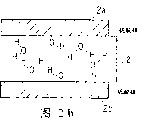
Fig. 8 is the figure of the relation of expression crystal axis of piezoelectric substrate and cutting angle.
Fig. 9 is the figure of the relation of expression cutting angle of lithium niobate substrate and piezoelectric constant.
Figure 10 is the frequency characteristic figure of the acceleration transducer of the present invention the 1st embodiment.
Figure 11 is the figure of cutting angle of the acceleration transducer of expression the present invention the 1st embodiment.
Figure 12 is the figure of the relation of expression cutting angle of quartz base plate and piezoelectric constant.
Figure 13 is the figure of the relation of expression cutting angle of quartz base plate and piezoelectric constant.
Figure 14 is the figure of the relation of expression cutting angle of quartz base plate and piezoelectric constant.
Figure 15 is the sectional view of machine-electric inverting element that expression is used for the acceleration transducer of the present invention the 2nd embodiment.
Figure 16 is the exploded perspective view of an example of the acceleration transducer of expression the present invention the 2nd embodiment.
Figure 17 is the sectional view of an example of the acceleration transducer of expression the present invention the 2nd embodiment.
Figure 18 is other routine exploded perspective views of the acceleration transducer of expression the present invention the 2nd embodiment.
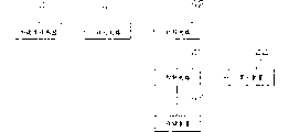
Figure 19 is the process chart of manufacture method of the acceleration transducer of expression the present invention the 3rd embodiment.
Figure 20 is the process chart of manufacture method of the acceleration transducer of expression the present invention the 3rd embodiment.
Figure 21 is the exploded perspective view of an example of the acceleration transducer of expression the present invention the 4th embodiment.
Figure 22 is other routine exploded perspective views of the acceleration transducer of expression the present invention the 4th embodiment.
Figure 23 is the circuit structure diagram of the shock testing device of the present invention the 5th embodiment.
Figure 24 is the circuit diagram of amplifying circuit of the shock testing device of expression the present invention the 5th embodiment.
Figure 25 be expression when measuring with the shock testing device of the present invention the 5th embodiment output and the figure of relationship with acceleration.
Figure 26 is the oblique view of the bimorph formula machine-electric inverting element of expression prior art.
Figure 27 is the sectional view of bimorph formula machine-electric inverting element of the cantilever beam structure of expression prior art.
Figure 28 is the sectional view of bimorph formula machine-electric inverting element of the both arms girder construction of expression prior art.
(the 1st embodiment)
Fig. 1 is the oblique view of machine-electric inverting element that expression is used for the acceleration transducer of the present invention the 1st embodiment.As shown in Figure 1, piezoelectric substrate 2a, 2b by the rectangular lithium niobate (LiNbO3) of the thick 50 μ m with 2 relative interareas, wide 0.5mm, long 2mm constitutes directly engage between its interarea, constitute piezoelectric element 2 with this.Here, piezoelectric substrate 2a and piezoelectric substrate 2b become mutually opposite direction with the direction of polaxis and engage.On 2 relative interareas of piezoelectric element 2, form electrode 3a, 3b that the chromium-Jin by thick 0.2 μ m constitutes respectively.Constitute the machine-electric inverting element 1 of bimorph formula with this.
Below, an example of the manufacture method of the machine-electric inverting element with said structure is described.
Fig. 2 is the key diagram of interfacial state of piezoelectric substrate in each stage of direct joint of manufacture method of the machine-electric inverting element of the expression acceleration transducer that is used for the present invention the 1st embodiment.Among Fig. 2, L1, L2, L3 represent the distance between piezoelectric substrate.At first, piezoelectric substrate 2a, 2b are promptly carried out mirror ultrafinish in the two sides of 2 lithium niobate substrates.Then, with these piezoelectric substrates 2a, 2b by mixed solution (ammoniacal liquor: aquae hydrogenii dioxidi: water=1: 1: 6 (volume ratio)) clean, piezoelectric substrate 2a, 2b are carried out hydrophilicity-imparting treatment with ammonia and hydrogen peroxide and water.Shown in Fig. 2 (a), terminal processes is carried out with hydroxyl (OH yl) in the surface of piezoelectric substrate 2a, 2b that above-mentioned mixed solution cleaned, becomes water wettability (state before engaging).
Secondly, shown in Fig. 2 (b), 2 piezoelectric substrates (lithium niobate) 2a, the 2b that will carry out hydrophilicity-imparting treatment becomes mutually opposite direction with the direction of polaxis and engages (L1>L2).Like this, cause dehydration, piezoelectric substrate (lithium niobate) 2a and piezoelectric substrate (lithium niobate) 2b just overlap owing to-OH and hydrogen in conjunction with etc. gravitation attract each other and engage.
Then, piezoelectric substrate (lithium niobate) 2a, the 2b to above-mentioned joint heat-treats under 450 ℃.Like this, shown in Fig. 2 (c), just (L2>L3), piezoelectric substrate 2a, 2b are joined directly on atomic level securely to become the state of covalent bonds by oxygen (O) between the constituting atom of the constituting atom of piezoelectric substrate (lithium niobate) 2a and piezoelectric substrate (lithium niobate) 2b.That is, can obtain not exist the bonding state of adhesive linkage such as bonding agent at the interface that engages.Perhaps, also become the state of covalent bonds sometimes between the constituting atom of the constituting atom of piezoelectric substrate (lithium niobate) 2a and piezoelectric substrate (lithium niobate) 2b by hydroxyl, piezoelectric substrate 2a, 2b are joined directly on atomic level securely.。
The Curie point of lithium niobate is 1210 ℃, because by approaching therewith temperature experience, characteristic will worsen, so, wish that heat treatment temperature is less than Curie point.
Face by process the mirror ultrafinish that will wish to engage carries out making its contact after the surface treatment and the joint that directly do not take place between the interface by adhesive linkages such as bonding agents is called " directly joint ".Usually, by heat-treating formation, the joint that is formed by molecular force is the joint of the brute force of atomic levels such as covalent bonds and ions binding.
Then, on 2 relative interareas that direct piezoelectric substrate (lithium niobate) 2a, the 2b that engages is piezoelectric element, utilize Vacuum Coating method to plate chromium-Jin film, form electrode 3a, 3b (referring to Fig. 1).At last, use cast-cutting saw to be cut into the short plate shape of specifying size, thereby be made into bimorph formula machine-electric inverting element 1.
As shown in Figure 3, directly joint also can be undertaken by the cushion 46 that is made of silicon oxide film etc.Promptly, on the interarea on one side of piezoelectric substrate 2a, form the cushion 46 that constitutes by the silicon oxide film of thick 0.1 μ m etc., after this cushion 46 and another piezoelectric substrate 2b carried out hydrophilicity-imparting treatment, both are overlapped, by heat-treating, the constituting atom of the constituting atom of piezoelectric substrate 2b and cushion 46 engages by oxygen or hydroxyl.Even on the composition surface, have to rise and fall and when concavo-convex or when having foreign matter such as dust to be attached on the composition surface because absorb by cushion 46 concavo-convex etc., so, can directly engage at an easy rate.In addition, even situation about engaging for the material that is difficult to form from the teeth outwards oxygen and hydroxyl because of hydrophilicity-imparting treatment engages by cushion 46, also can directly engage at an easy rate.At this moment, cushion both can only be arranged on 10,000 of the predetermined face that engages, also can be arranged on both sides' the face.In addition, as the material of cushion, except monox, can also use for example silicon nitride, metal silicide etc.
Fig. 4 is the oblique view of bimorph formula machine-electric inverting element of the cantilever beam structure of expression the present invention the 1st embodiment, and Fig. 5 is its sectional view.As Fig. 4, shown in Figure 5, piezoelectric substrate 2a, 2b by the rectangular lithium niobate of the thick 50 μ m with 2 relative interareas, wide 0.5mm, long 2mm constitutes directly engage between its interarea, constitute piezoelectric element 2 with this.Here, piezoelectric substrate 2a and piezoelectric substrate 2b become mutually opposite direction with the direction that is polarizing and engage.One end of piezoelectric element 2 is to be fixed by the support 4a that is made of LiNbO3, the state of 4b clamping.Here, piezoelectric element 2 directly engages with support 4a, 4b.At this moment, piezoelectric element 2 can be undertaken by the cushion that is made of silicon oxide film etc. with direct the joint also of support 4a, 4b.On 2 relative interareas of piezoelectric element 2, form electrode 3a, 3b that the chromium-Jin by thick 0.2 μ m constitutes respectively, these electrodes 3a, 3b also form on support 4a, 4b continuously.Like this, just constituted the bimorph formula machine-electric inverting element 1 of cantilever beam structure.
Fig. 6 is the exploded perspective view of an example of the acceleration transducer of expression the present invention the 1st embodiment.As shown in Figure 6, the bimorph formula machine-electric inverting element 1 with cantilever beam structure of Fig. 4, structure shown in Figure 5 is accommodated by utilizing method such as corrosion in central portion forms the container 10b that the lithium niobate of depressed part constitutes.Promptly, part beyond support 4a, the 4b of bimorph formula machine-electric inverting element 1 remains under the state on the depressed part, and support 4a, the 4b of bimorph formula machine-electric inverting element 1 utilizes conductive paste 5a, 5b (5a is not shown) to be fixed on the container 10b.Overlapping bonding by equally forming container 10a and container 10b that the lithium niobate of depressed part constitutes at central portion.Like this, whole bimorph formula machine-electric inverting element 1 is just covered by container 10a, 10b.In the inside of container 10b, form the conductive layer 7a, the 7b that constitute by silver-palladium, the end of conductive layer 7a, 7b is electrically connected with electrode 3a, the 3b of bimorph formula machine-electric inverting element 1 respectively by conductive paste 5a, 5b.In addition, form outer electrode 9a, the 9b that is made of nickel on the both ends of the surface of container 10a, 10b, the other end of conductive layer 7a, 7b is electrically connected with outer electrode 9a, 9b respectively.That is, electrode 3a, the 3b of bimorph formula machine-electric inverting element 1 are electrically connected with outer electrode 9a, 9b respectively by conductive paste 5a, 5b and conductive layer 7a, 7b.Like this, just, the electric charge that bimorph formula machine-electric inverting element 1 takes place can be fetched into the outside.Utilize said structure to constitute acceleration transducer 100.
When acceleration was added on the object that acceleration transducer 100 shown in Figure 6 is installed, the power that is directly proportional with acceleration just passed to machine-electric inverting element 1 by container 10a, 10b, support 4a, 4b.When above-below direction (direction of arrow of Fig. 4) produced acceleration, machine-electric inverting element 1 was just crooked along the vertical direction, and vibration bends.This situation is shown in Fig. 7.If the crooked downwards situation (solid line of Fig. 7) of machine-electric inverting element 1 that consideration is made of piezoelectric substrate 2a, 2b, because piezoelectric substrate 2a is positioned at upside with respect to the central shaft of machine-electric inverting element 1, so, in piezoelectric substrate 2a, will occur in such distortion that is stretched under the tension force effect.On the other hand, because piezoelectric substrate 2b is positioned at downside with respect to the central shaft of machine-electric inverting element 1, so, in piezoelectric substrate 2b, will occur in the distortion of shrinking under the compression force.
Under the situation of piezoelectric ceramic substrate is the bonding and machine that has earlier-electric inverting element of making, owing between piezoelectric substrate, there is bonding agent than piezoelectric substrate softness, so, when machine-electric inverting element is crooked along the vertical direction, flexural vibrations will be absorbed by bonding agent, thereby the stress that produces in piezoelectric substrate will reduce.Therefore, the electromotive force that takes place in piezoelectric substrate also reduces.
But the machine of present embodiment-electric inverting element 1 is owing to make by piezoelectric substrate 2a, 2b are directly engaged, so, between piezoelectric substrate 2a, 2b, there are not adhesive linkages such as bonding agent.That is, when machine-electric inverting element 1 bends vibration owing to acceleration, just there is not the problem that absorbs these flexural vibrations.Therefore, the terrestrial stress that generation is not decreased in piezoelectric substrate 2a, 2b, thus can obtain big electromotive force.As a result, can realize having the acceleration transducer of high sensitivity.In addition, because the engagement state of piezoelectric substrate 2a, 2b is even, so the machine-resonant frequency of electric inverting element 1 and the deviation of sensitivity are very little.In addition, owing between piezoelectric substrate 2a, 2b, do not have adhesive linkage, so the vibration characteristics of machine-electric inverting element 1 can not vary with temperature and change.
In addition, owing to support 4a, 4b engage on atomic level securely with machine-electric inverting element 1, so the acceleration that is added on the object that container 10a, 10b are installed does not pass to machine-electric inverting element 1 with not losing.
In the piezoelectric substrate 2a, the 2b that constitute by lithium niobate etc., the electric charge that caused by compression stress, drawing stress takes place in the top and bottom of piezoelectric substrate 2a, 2b, but, mutually opposite direction engages because piezoelectric substrate 2a and piezoelectric substrate 2b become with the direction of polaxis, so, although the stress difference that in piezoelectric substrate 2a, 2b, takes place, one is compression stress, one is drawing stress, still, the electric charge of identical polar takes place but on piezoelectric substrate 2a and piezoelectric substrate 2b.That is the electromotive force (referring to Fig. 7) of equidirectional, takes place on piezoelectric substrate 2a and piezoelectric substrate 2b.Therefore, electrode 3a, the 3b that can form from the two sides at machine-electric inverting element 1 obtains the signal of the size of reflection acceleration.If the thickness direction of lithium niobate substrate is set at Y ' direction of principal axis, length direction is set at Z ' direction of principal axis, then compression stress and drawing stress will be along the effects of Z ' direction of principal axis, and electric charge takes place along Y ' direction of principal axis.At this moment, the quantity of electric charge of generation and piezoelectric constant d23 ' relation is very big.In addition, the size of this piezoelectric constant d23 ' with Y ' axle, which direction Z ' axle is taken at respect to crystal axis alters a great deal.That is, the sensitivity of acceleration transducer alters a great deal with the direction of Y ' axle and Z ' axle.When suitably setting Y ' axle and Z ' axle, when selection makes the absolute value of the size of piezoelectric constant d23 ' be the cutting angle of maximum, just can obtain the best acceleration transducer of sensitivity.
Fig. 8 is the crystal axis of lithium niobate substrate and the relation of cutting angle.In Fig. 8, X-axis, Y-axis, Z axle are represented the direction of the crystal axis of lithium niobate, and X ' axle (=X-axis), Y ' axle, the expression of Z ' axle are the orthogonal axes of center when Y-axis is rotated the θ angle with the X-axis.That is the cut direction of X ' axle (=X-axis), Y ' axle, Z ' axle expression lithium niobate substrate.When setting the direction of each as shown in Figure 8, with the thickness direction of lithium niobate substrate be set at X ' direction of principal axis, when length direction is set at Y ' direction of principal axis, piezoelectric constant d12 ' is very big with the relation of the sensitivity of acceleration transducer.In addition, with the thickness direction of lithium niobate substrate be set at X ' direction of principal axis, when length direction is set at Z ' direction of principal axis, piezoelectric constant d13 ' is very big with the relation of the sensitivity of acceleration transducer.In addition, with the thickness direction of lithium niobate substrate be set at Y ' direction of principal axis, when length direction is set at X ' direction of principal axis, piezoelectric constant d21 ' is very big with the relation of the sensitivity of acceleration transducer.In addition, with the thickness direction of lithium niobate substrate be set at Y ' direction of principal axis, when length direction is set at Z ' direction of principal axis, piezoelectric constant d23 ' is very big with the relation of the sensitivity of acceleration transducer.In addition, with the thickness direction of lithium niobate substrate be set at Z ' direction of principal axis, when length direction is set at X ' direction of principal axis, piezoelectric constant d31 ' is very big with the relation of the sensitivity of acceleration transducer.In addition, with the thickness direction of lithium niobate substrate be set at Z ' direction of principal axis, when length direction is set at Y ' direction of principal axis, piezoelectric constant d32 ' is very big with the relation of the sensitivity of acceleration transducer.
Fig. 9 is the cutting angle of lithium niobate substrate and the relation of piezoelectric constant.As shown in Figure 9, when cutting angle was 140 °, piezoelectric constant d23 ' had maximum value.Actual experimental result when changing cutting angle maker-electric inverting element is shown in following table 1 and Figure 10.
Table 1
| Cutting angle [°] | Piezoelectric constant d23 ' [C/N] | Sensitivity [mV/G] |
| Y-cuts 135 ° of Z ' directions | -2.99×10 -11 | 6.1 |
| Y-cuts 135 ° of directions Xs | 1.40×10 -11 | 3.7 |
| Y-cuts 140 ° of Z ' directions | -3.06×10 -11 | 6.4 |
| Y-cuts 140 ° of directions Xs | 1.53×10 -11 | 3.8 |
| Y-cuts 165 ° of Y directions | 1.98×10 -11 | 4.6 |
| Z- | 0.0 | Non sensitivity |
| Z- | 0.0 | Non sensitivity |
By shown in the above-mentioned table 1 as can be known, use 140 ° of substrates of Y-cutting of piezoelectric constant maximum, be that the electric charge that machine-electric inverting element takes place of length direction is maximum with Z ' direction of principal axis, sensitivity the best.Figure 11 is the relation of the cutting angle of acceleration transducer at this moment.Being the center with X-axis shown in Figure 11 rotates Y-axis 140 °, electrode is arranged on the face vertical with Y ' axle, length direction is set at the axial acceleration transducer of Z ' has the highest sensitivity.
Crystal Structure of Lithium Niobate is a rhombohedral 3m family, is to be 3 symmetrical structures in center with the Z axle.Therefore, exist several to have the cutting angle of same piezoelectric constant.For example, as shown in Figure 9, the piezoelectric constant d23 ' of 50 ° of cutting angles and 230 ° piezoelectric constant d32 ' and 140 ° of cutting angles and 320 ° is identical value.If the consideration symmetry of crystals can be understood this point.
In addition, near the cutting angle the optimal cutting angle of sensitivity maximum, the relation of piezoelectric constant and cutting angle is smaller, is best even strictly do not make cutting angle, also can obtain sensitivity much at one.If thinking strictly to make cutting angle is optimal cutting angle, then the high precision int by the processing of regulation cutting angle strictly, will become problem for the increase of the complicated processing charges that causes of the operation that suppresses deviation and the increase that qualification rate reduces the unit price that causes.With regard to piezoelectric constant d
23 ', as shown in Figure 9, optimal cutting angle is 140 °, still, as long as cutting angle is in 129 °~152 ° the scope, it is peaked 90~100% that piezoelectric constant just becomes, and the problem that sensitivity worsens just can not take place.In addition, with the thickness direction of lithium niobate substrate be set at Y ' direction of principal axis, when length direction is set at X-direction, the sensitivity of acceleration transducer and piezoelectric constant d
21 'Relevant.As shown in Figure 9, piezoelectric constant d
21 'With the relation of cutting angle than piezoelectric constant d
23 'Little with the relation of cutting angle.At this moment, as long as cutting angle is in optimal cutting angle ± 26 °, piezoelectric constant just becomes peaked 90~100% value, thereby the problem that sensitivity worsens can not take place.Therefore,, also can make highly sensitive acceleration transducer even do not process cutting angle accurately, so, the processing charges cheapness.If the cutting angle of 2 piezoelectric substrates has difference, the problem that the electric charge that produces with regard to the thermoelectric effect that exists by piezoelectrics can not be offset, so, the difference of the cutting angle of best 2 piezoelectric substrates is the smaller the better, but, because the relation of piezoelectric constant and cutting angle is little, so, the difference of cutting angle of 2 piezoelectric substrates that needs only formation machine-electric inverting element at 1 ° with interior just passable.
The frequency range of the length of machine-electric inverting element, thickness and the width acceleration by being considered as measuring object determines.The frequency of the acceleration of measuring is more near the resonant frequency of machine-electric inverting element, and the sensitivity of acceleration transducer is high more.The resonant frequency of machine-electric inverting element 1 that 2 lithium niobate substrates directly engage, the length setting from the front end to the support is the cantilever beam structure of 2mm of thickness 50 μ m is 20kHz.By the measurement result of the frequency of the sensitivity of Figure 10 and acceleration as can be known, the frequency of acceleration is during greater than 10kHz, because near the resonant frequency of machine-electric inverting element 1, so sensitivity is increased.In the survey frequency scope, little for the relation of the sensitivity that makes acceleration transducer and frequency, must make resonant frequency away from the survey frequency scope.Therefore, for example, machine-electric inverting element 1 can be designed to 2 times the frequency that resonant frequency becomes the highest measurement frequency.As mentioned above, the resonant frequency of machine-electric inverting element 1 depends on its length and thickness.The situation of the acceleration transducer of the use piezoelectric ceramics that has earlier, the support of machine-electric inverting element is undertaken by bonding agent.The applying amount of control bonding agent is difficult, because overflowing of bonding agent waits the physical length of machine-electric inverting element to shorten, thus the deviation increase.Therefore, under the situation of the acceleration transducer of the use piezoelectric ceramics that formerly has, because the resonant frequency deviation of machine-electric inverting element, so, exist the sensitivity of high-frequency region will produce deviation, perhaps measurable frequency is problems such as variation with each acceleration transducer.Under the situation of present embodiment, because support 4a, 4b are directly engaged with machine-electric inverting element 1, so the deviation of the length of machine-electric inverting element 1 is very little.As a result, the deviation of the resonant frequency of machine-electric inverting element 1 is just very little, thereby each acceleration transducer is just very little in the variation of the sensitivity of high-frequency region and survey frequency scope.
The lithium niobate that uses as piezoelectric is a monocrystalline, and the deviation of its piezoelectric constant, specific inductive capacity, elastic constant etc. is very little.For piezoelectric ceramics, have an appointment usually 20% deviation of these material constants.Therefore, use also have an appointment 20% deviation of the sensitivity of acceleration transducer of piezoelectric ceramics and resonant frequency.But in the acceleration transducer of the present embodiment of making in that lithium niobate substrate is directly engaged, sensitivity and resonant frequency can be suppressed to its deviation less than 5%.
In addition, piezoelectric ceramics is big over time, deficient in stability.Therefore, there is the problem of sensitivity time to time change about 10~15% in the acceleration transducer of use piezoelectric ceramics.But, lithium niobate substrate directly engaged and the acceleration transducer of the present embodiment made is highly stable, over time less than 2%.
As the material of piezoelectric substrate 2a, 2b, can be the mono-crystalline piezoelectric materials that can directly engage, except lithium niobate, can also use lithium tantalate (LiTaO3), quartz, Langasite type piezoelectric crystal etc.As Langasite type piezoelectric crystal, have: La
3Ga
5SiO
14La
3Ga
5.5Nb
0.5O
14La
3Ga
5.5Ta
0.5O
14The crystal structure of lithium tantalate is the same with lithium niobate, is rhombohedral 3m family, and its optimal cutting angle is identical with lithium niobate.In addition, the crystal structure of quartz and Langasite type piezoelectric crystal is rhombohedral 32 families.Figure 12~Figure 14 has the cutting angle of quartz base plate of crystal structure of 32 families and the relation of piezoelectric constant.Figure 12 is to be the cutting angle and the relation of piezoelectric constant of turning axle when rotating with the X-axis, Figure 13 be with the Y-axis be turning axle when rotating cutting angle and the relation of piezoelectric constant, Figure 14 is the cutting angle when being the turning axle rotation with the Z axle and the relation of piezoelectric constant.In addition, the relation of the cutting angle of the substrate that is made of Langasite type piezoelectric crystal and piezoelectric constant too.
The optimal cutting angle of mono-crystalline piezoelectric materials of the crystal structure of the optimal cutting angle of mono-crystalline piezoelectric materials of the crystal structure of obtaining according to Figure 12~Figure 14 with 32 families and the foregoing 3m of having family is shown in following table 2 in the lump.
(table 2)
| Crystal structure | The material name | Optimal cutting angle (Eulerian angle) | Maximum piezoelectric constant |
| The 3m trigonal system | The lithium | 140,0,0 | |
| 0,0,0 | d 21′ | ||
| 32 trigonal systems | Quartzy Langasite type | 70,0,0 | |
| 0,0,0 | | ||
| 0,0,90 | d 21′ |
[appendix] and then also comprise with the Z axle being that the center is rotated 120 ° cutting angle and is that 180 ° angle is rotated at the center with X-axis and Y-axis respectively.
In above-mentioned table 2,3 digital sequence lists of Eulerian angle show that with X-axis, Y-axis, Z axle be the angle of rotation at center.In addition, in above-mentioned table 2, also show maximum piezoelectric constant.Shown in above-mentioned table 2, when the piezoelectrics that will have a crystal structure of 32 families rotated 70 ° with X-axis as turning axle, maximum piezoelectric constant was d
13 'When the piezoelectrics that this expression will have a crystal structure of 32 families rotate 70 ° with X-axis as turning axle, perpendicular to the X ' axle (=X-axis) direction after rotating cut out piezoelectric substrate, when the length direction of piezoelectric substrate is set at Z ' direction of principal axis, sensitivity is the highest.In addition, when Eulerian angle were (0,0,0), maximum piezoelectric constant was d
12 'This expression is when Eulerian angle when be (0,0,0), perpendicular to the X ' axle (=X-axis) direction after the rotation cut out piezoelectric substrate, when the length direction of piezoelectric substrate is set at Y ' direction of principal axis, sensitivity is the highest.In addition, when Eulerian angle were (0,0,90), maximum piezoelectric constant was d
21 'This expression is when Eulerian angle when be (0,0,90), perpendicular to the Y ' direction of principal axis after the rotation cut out piezoelectric substrate, when the length direction of piezoelectric substrate is set at X ' direction of principal axis, sensitivity is the highest.
In addition, under the situation of the piezoelectric substrate (quartz, Langasite type piezoelectric crystal etc.) of crystal structure, for d with 32 families
13 ', d
12 'And d
32 'Respectively in+52 °~+ 86 ° scope, ± 26 ° scope in and in+52 °~+ 68 ° the scope piezoelectric constant become peakedly 90~100%, the problem of sensitivity deterioration can not take place.Therefore,, also can make highly sensitive acceleration transducer even do not process cutting angle accurately, so, the processing charges cheapness.
As mentioned above, according to present embodiment, owing to do not use adhesive linkage such as bonding agent, by piezoelectric substrate 2a, 2b are directly engaged and formation machine-electric inverting element 1 securely, so, can realize not having the highly sensitive acceleration transducer that has of characteristic deviation and rotational delay etc.In addition, machine-electric inverting element 1 is not directly engaged with support 4a, 4b owing to do not use bonding agent, so, can carry out the position adjustment of machine-electric inverting element 1 accurately.As a result, can realize length and the status of support bias free and stable high, the very small acceleration transducer of characteristic dispersion of semi-girder.In addition, owing to do not use bonding agent machine-electric inverting element 1 is not directly engaged with support 4a, 4b, so acceleration can pass to machine-electric inverting element 1 with not losing.
In the present embodiment, the material as electrode 3a, 3b is to use chromium-Jin, still, not necessarily is limited to this material, for example, also can use gold, chromium, silver or alloy material.
In addition, in the present embodiment, the material as container 10a, 10b is to use lithium niobate, still, not necessarily is limited to this material, for example, also can use materials such as pottery such as lithium tantalate, quartz, glass, plastics, aluminium oxide.
In addition, in the present embodiment, machine-electric inverting element 1 is adopted cantilever beam structure, but, not necessarily be limited to this structure, also the two ends of machine-electric inverting element 1 directly can be engaged with support and make the both arms girder construction, in addition, the center of machine-electric inverting element 1 directly can also be engaged as the center supporting structure with support.
(the 2nd embodiment)
Figure 15 is the sectional view of machine-electric inverting element that expression is used for the acceleration transducer of the present invention the 2nd embodiment.As shown in figure 15, directly engage between its interarea of piezoelectric substrate 2a, 2b that constitutes by the rectangular lithium niobate of the thick 50 μ m with 2 relative interareas, wide 0.5mm, long 2mm, constitute piezoelectric element 2 with this.Here, piezoelectric substrate 2a and piezoelectric substrate 2b become mutually opposite direction with the direction of polaxis and engage.One end of piezoelectric element 2 is fixed with the support 4a that is made of lithium niobate, the state of 4b clamping.Here, piezoelectric element 2 directly engages with support 4a, 4b.On 2 relative interareas of piezoelectric element 2, form electrode 3a, the 3b that the chromium-Jin by thickness 0.2 μ m constitutes respectively in the part that is not supported body 4a, 4b clamping.Like this, just, constitute the machine-electric inverting element 1 of the bimorph formula of cantilever beam structure.
Figure 16 is the exploded perspective view of an example of the acceleration transducer of expression the present invention the 2nd embodiment, and Figure 17 is its sectional view.As Figure 16, shown in Figure 17, have the cantilever beam structure of structure shown in Figure 15 machine-electric inverting element 1 is accommodated in the above, in the container 10c that constitutes by lithium niobate of an end face and a lateral opening, support 4a, 4b directly engage with the inboard of other end of container 10c.At this moment, support 4a, 4b can be undertaken by the cushion that is made of silicon oxide film etc. with direct the joint also of container 10c.Under the state that support 4a, 4b and container 10c are overlapped, the end of conductive layer 7c, 7d is connected with electrode 3a, 3b, the other end of conductive layer 7c, 7d exposes from the end of container 10c.The container 10d identical with container 10c shape that is made of identical lithium niobate engages with container 10c.Outside at container 10c, 10d forms outer electrode 9c, the 9d that is made of nickel, and outer electrode 9c, 9d are electrically connected with conductive layer 7c, 7d respectively.That is, electrode 3a, the 3b of machine-electric inverting element 1 are electrically connected by conductive layer 7c, 7d and outer electrode 9c, 9d.Like this, just, the electric charge that machine-electric inverting element 1 takes place can be fetched into the outside.Like this, just constituted acceleration transducer 102.
In acceleration transducer shown in Figure 17 102, when above-below direction applies acceleration, machine-just vibration along the vertical direction of electric inverting element 1, vibration bends.When bending vibration, the distortion that stretches takes place in the side of piezoelectric substrate (lithium niobate) 2a, 2b, and the compression distortion takes place the opposing party.Here, because piezoelectric substrate 2a and piezoelectric substrate 2b become mutually opposite direction with polaxis and engage, so, although the stress difference that in piezoelectric substrate 2a, 2b, takes place, one is compression stress, one is drawing stress, still, the electric charge of identical polar takes place but on piezoelectric substrate 2a and piezoelectric substrate 2b.That is the electromotive force of equidirectional, takes place in piezoelectric substrate 2a and piezoelectric substrate 2b.Therefore, electrode 3a, the 3b that can form from the two sides at machine-electric inverting element 1 obtains the signal of the size of reflection acceleration.
Figure 18 is other routine exploded perspective views of the acceleration transducer of expression the present invention the 2nd embodiment.As shown in figure 18, directly engage between its interarea of piezoelectric substrate 2a, 2b that constitutes by the rectangular lithium niobate of the thick 50 μ m with 2 relative interareas, wide 0.5mm, long 2mm, constitute piezoelectric element 2 with this.Here, piezoelectric substrate 2a and piezoelectric substrate 2b become mutually opposite direction with polaxis and engage.On 2 relative interareas of piezoelectric element 2, form electrode 3a, 3b that the chromium-Jin by thickness 0.2 μ m constitutes.Like this, just, constitute machine-electric inverting element 1.One end of machine-electric inverting element 1 is clamped by top and bottom opening, the container 10e, the 10f that are made of lithium niobate that are divided into two, with this support machine-electric inverting element 1.Here, container 10e, 10f and machine-electric inverting element 1 directly engages, and in addition, also directly engages between container 10e, the 10f.At this moment, the direct joint of container 10e, 10f and machine-electric inverting element 1 or the direct joint between container 10e, the 10f also can be undertaken by the cushion that is made of silicon oxide film etc.Container 10g, 10h use the top and bottom of bonding agent and container 10e, 10f to be adhesively fixed.Like this, machine-electric inverting element 1 just is sealed up in a container.Form the outer electrode 9e, the 9f that are made of nickel on the both ends of the surface of container respectively, this outer electrode 9e, 9f are electrically connected with electrode 3a, the 3b of machine-electric inverting element 1 respectively by not shown conductive layer.Like this, just, the electric charge that machine-electric inverting element 1 takes place can be fetched into the outside.In addition, depressed part is set at the inside surface of container 10g, 10h, so that machine-electric inverting element 1 can not contact with machine-electric inverting element 1 when crooked.Like this, just constituted acceleration transducer 103.
The frequency range that length, thickness and the width of machine-electric inverting element 1 is considered as the acceleration of measuring object determines.The frequency of the acceleration of measuring is more near the resonant frequency of machine-electric inverting element 1, and the sensitivity of acceleration transducer is high more.In the survey frequency scope, little for the relation of the sensitivity that makes acceleration transducer and frequency, must make resonant frequency away from the survey frequency scope.Therefore, for example machine-electric inverting element 1 can be designed to 2 times the frequency that resonant frequency is the highest measurement frequency.
The lithium niobate that uses as piezoelectric is a monocrystalline, and the deviation of its piezoelectric constant, specific inductive capacity, elastic constant etc. is very little.Under the situation of piezoelectric ceramics, have an appointment usually 20% deviation of these material constants.Therefore, use also have an appointment 20% deviation of the sensitivity of acceleration transducer of piezoelectric ceramics and resonant frequency.But in the acceleration transducer of the present embodiment of making in that lithium niobate substrate is directly engaged, sensitivity and resonant frequency can be suppressed to deviation less than 5%.
In addition, piezoelectric ceramics is big over time, deficient in stability.Therefore, there is the problem of sensitivity time to time change about 10~15% in the acceleration transducer of use piezoelectric ceramics.But, lithium niobate substrate directly engaged and the acceleration transducer of the present embodiment made is highly stable, over time less than 2%.
As mentioned above, according to present embodiment, owing to do not use adhesive linkage such as bonding agent, by piezoelectric substrate 2a, 2b are directly engaged and formation machine-electric inverting element 1 securely, so, can realize not having the highly sensitive acceleration transducer that has of characteristic deviation and vibration damping etc.In addition, machine-electric inverting element 1 is not directly engaged with support 4a, 4b owing to do not use bonding agent, so, can carry out the position adjustment of machine-electric inverting element 1 accurately.As a result, can realize length and the status of support bias free and stable high, the very small acceleration transducer of characteristic dispersion of semi-girder.In addition, do not use bonding agent and by machine-electric inverting element 1 is directly engaged with support 4a, 4b, acceleration can pass to machine-electric inverting element 1 with not losing.In addition, by thereby directly being engaged support 4a, 4b with support 4a, 4b, machine-electric inverting element 1 do not engage securely from the container that the practical set face directly transmits with acceleration owing to do not use bonding agent, so acceleration can pass to machine-electric inverting element 1 with not losing.
In addition, in the present embodiment, be to use lithium niobate as the material of piezoelectric substrate 2a, 2b, but not necessarily be limited to this material, for example, also can use lithium tantalate and quartz.
In addition, in the present embodiment, be to use chromium-Jin, still, not necessarily be limited to this material, for example, also can use gold, chromium, silver or alloy material as the material of electrode 3a, 3b.
In addition, in the present embodiment, be to use lithium niobate, still, not necessarily be limited to this material, for example, also can use glass, pottery, resin etc. as the material of container.
In addition, in the present embodiment, as support 4a, the 4b of machine-electric inverting element 1 in container fixed form and the fixed form of container be to use direct joint, but, not necessarily be limited to this mode, use bonding agent to fix, also can bring into play same characteristic.
In addition, in the present embodiment, machine-electric inverting element 1 is adopted cantilever beam structure, but, not necessarily be limited to this structure, the both arms girder construction that also can adopt two ends and support with machine-electric inverting element 1 directly to engage, in addition, the center supporting structure that can also adopt center and support with machine-electric inverting element 1 directly to engage.
(the 3rd embodiment)
Below, acceleration transducer and manufacture method thereof with cantilever beam structure identical with Figure 16~Figure 18 are described.
Figure 19, Figure 20 are the process charts of manufacture method of the acceleration transducer of expression the present invention the 3rd embodiment.
At first, shown in Figure 19 (a),, use lithium niobate substrate, utilize the sand-blast formation semi-girder 11a of portion, the 11b of photoresists model as mask parts as piezoelectric substrate 12a, 12b.
Secondly, shown in Figure 19 (b), form the piezoelectric substrate 12a of the semi-girder 11a of portion and the piezoelectric substrate 12b of the formation semi-girder 11b of portion and engage by direct joint.Directly engage will become mutually opposite direction joint as described above with the polaxis direction after, to heat-treat and carry out through 2 piezoelectric substrate 12a, 12b of hydrophilicity-imparting treatment.At this moment, piezoelectric substrate 12a can be undertaken by the cushion that is made of silicon oxide film etc. with direct the joint also of piezoelectric substrate 12b.
Then, shown in Figure 19 (c), the two sides in semi-girder portion utilizes Vacuum Coating method to plate chromium-gold thin film and forms electrode 13a, 13b.Like this, just, can obtain the bimorph formula machine-electric inverting element 15 of cantilever beam structure.Machine-electric inverting element 15 is supported as support sector with the open circumferential of piezoelectric substrate 12a, 12b.In addition, with the face of electrode 13a the same side of piezoelectric substrate 12a on form conductive layer 14a with state with electrode 13a conducting.This conductive layer 14a is used for taking place on electrode 13a electric charge is fetched into outer electrode 20a (Figure 20 (b), (c)).In addition, with the face of electrode 13b the same side of piezoelectric substrate 12b on form conductive layer 14b so that an opposite side (right side of the figure) conducting of the opening of semi-girder portion and piezoelectric substrate 12b.At this moment, if conductive layer 14a or conductive layer 14b and electrode 13a or electrode 13b are formed simultaneously, just can simplify manufacturing process.
Secondly, shown in Figure 20 (a), on other lithium niobate substrate, use, make container 16a, 16b the sand-blast formation recess 17 of photoresists model as mask parts.In addition, be formed for simultaneously on this container 16a, the 16b with piezoelectric substrate 12a, 12b on conductive layer 14a, the through hole 18 that 14b is electrically connected.
Then, shown in Figure 20 (b), directly engage with container 16a, 16b by piezoelectric substrate 12a, the 12b that will form machine-electric inverting element 15.Like this, just machine-electric inverting element 15 is closed in container 16a, the 16b.At this moment, piezoelectric substrate 12a, 12b can be undertaken by the cushion that is made of silicon oxide film etc. with direct the joint also of container 16a, 16b.Because semi-girder portion utilizes model to form by lithium niobate substrate and support sector simultaneously, so support sector also has flexible, utilizes other lithium niobate substrate of double as container 16a, 16b and support sector to support more firmly.Because at the junction surface of piezoelectric substrate (lithium niobate) 12a, 12b and container (lithium niobate) 16a, 16b formation conductive layer (chromium-Jin) 14a, 14b, so, be difficult to piezoelectric substrate 12a, 12b are directly engaged with container 16a, 16b, but, if it is enough big that the bonding area of piezoelectric substrate 12a, 12b and container 16a, 16b is compared with the area of conductive layer 14a, 14b, just can engage securely.Then, conductive paste is poured in the through hole 18 of container 16a, 16b, form vertical conductive part 19a, 19b in order to be electrically connected with conductive layer 14a, 14b by sintering.In addition, at container 16a, above the 16b, printed silver-palladium, in order to vertical conductive part 19a, 19b conducting, form outer electrode 20a, 20b.Like this, electrode 13a, the 13b on machine-electric inverting element 15 and outer electrode 20a, 20b just form and are electrically connected.
Secondly, shown in Figure 20 (c), using cast-cutting saw is each acceleration transducer 104 with substrate cut.Machine-electric inverting element 15 has cantilever beam structure, engages securely with container 16a, 16b.
In the acceleration transducer 104 of Figure 20 (c), when applying acceleration along the vertical direction, machine-just vibration along the vertical direction of electric inverting element 15, thus bend vibration.When bending vibration, the distortion that stretches takes place in the side of piezoelectric substrate 12a, 12b, and the compression distortion takes place the opposing party.Here, because piezoelectric substrate 12a and piezoelectric substrate 12b are the directions with polaxis to be become mutual reverse direction and engages, so, although the stress that takes place in piezoelectric substrate 12a and piezoelectric substrate 12b is different, one is compression stress, one is drawing stress, still, the electric charge of identical polar takes place but on piezoelectric substrate 12a and piezoelectric substrate 12b.That is the electromotive force of equidirectional, takes place in piezoelectric substrate 12a and piezoelectric substrate 12b.Therefore, electrode 13a, the 13b that can form from the two sides at machine-electric inverting element 15 obtains the signal of the size of reflection acceleration.
The frequency range that length, thickness and the width of machine-electric inverting element 15 is considered as the acceleration of measuring object determines.The frequency of the acceleration of measuring is more near the resonant frequency of machine-electric inverting element 15, and the sensitivity of acceleration transducer 104 is high more.In the survey frequency scope, little for the relation of the sensitivity that makes acceleration transducer 104 and frequency, machine-electric inverting element 15 must be designed to 2 times the frequency that resonant frequency is the highest measurement frequency.
As mentioned above, according to present embodiment, owing to do not use adhesive linkage such as bonding agent by piezoelectric substrate 12a, 12b directly being engaged securely formation machine-electric inverting element 15, so, can realize not having characteristic deviation and vibration damping etc., having highly sensitive acceleration transducer 104.In addition, because machine-electric inverting element 15 utilizes model to form by piezoelectric substrate, so the deviation of the shape of machine-electric inverting element 15 is little.In addition, owing to machine-electric inverting element 15 forms simultaneously with support sector, so the deviation of the status of support of machine-electric inverting element 15 is little.Therefore, the deviation of the length of semi-girder is little, thereby can realize the very little acceleration transducers of characteristic deviation such as resonant frequency.In addition, owing to can form machine-electric inverting element 15, holding components and container 16a, 16b with commaterial, so, can realize not being subjected to the small-sized acceleration transducer of excellent in stability of the influence of distortion that temperature causes etc.In addition, owing on 1 substrate, make a large amount of acceleration transducers 1 time, so, can realize the acceleration transducer of production efficiency excellence.
In the present embodiment, as container 12a, the material of 12b is to use lithium niobate, still, not necessarily is limited to this material, for example, also can use lithium tantalate, quartz.
In the present embodiment, the material as container 16a, 16b is to use lithium niobate, still, not necessarily is limited to this material, for example, also can use materials such as lithium tantalate, quartz, silicon, glass.Preferably use piezoelectric substrate 12a, 12b identical materials with formation machine-electric inverting element 15, it would be desirable the approaching material of material thermal expansion coefficient with piezoelectric substrate 12a, the 12b of formation machine-electric inverting element 15.
In addition, in the present embodiment, the material as electrode 13a, 13b is to use chromium-Jin, but not necessarily is limited to this material, for example, also can use gold, chromium, silver or alloy material.
In addition, in the present embodiment, the material as vertical conductive part 19a, 19b is to use conductive paste, still, not necessarily is limited to this material, for example, also can use scolding tin and silver solder etc.
In addition, in the present embodiment, behind piezoelectric substrate (lithium niobate) 12a, the last formation of the 12b semi-girder 11a of portion, 11b, by they directly being engaged the machine-electric inverting element 15 that forms the bimorph formula, but, not necessarily be limited to this order, also 2 piezoelectric substrates (lithium niobate) 12a, 12b directly can be being engaged the back formation semi-girder 11a of portion, 11b.
In addition, in the present embodiment, after forming the semi-girder 11a of portion, 11b, form electrode 13a, 13b, still, not necessarily be limited to this order, also can after forming electrode 13a, 13b, form the semi-girder 11a of portion, 11b.
In addition, in the present embodiment, job operation and the recess 17 of container 16a, 16b and the job operation of through hole 18 as the 11a of semi-girder portion, 11b on piezoelectric substrate 12a, the 12b, use sand-blast, but, not necessarily be limited to this method, for example, also can use machinings such as universe burn into wet corrosion, Laser Processing, I.B.M., cutting and scroll saw, spray processing and electrodischarge machining etc.
In addition, in the present embodiment, the formation method as electrode 13a, 13b is to use Vacuum Coating method, still, not necessarily is limited to this method, for example, also can use gas phases such as sputtering method, CVD method to become embrane method and methods such as plating and printing.
In addition, in the present embodiment, with outer electrode 20a, 20b be arranged on container 16a, 16b above, still, not necessarily be limited to this structure, also can be arranged on the side of container 16a, 16b or cross over the side and above.
In addition, in the present embodiment, be to carry out being connected of conductive layer 14a, 14b and outer electrode 20a, 20b, still by through hole 18 is set on container 16a, 16b, not necessarily be limited to this method, also can be undertaken by otch etc. is set on container 16a, 16b.
In addition, when the existence owing to conductive layer 14a, 14b causes piezoelectric substrate (lithium niobate) 12a, the 12b of machine-electric inverting element 15 can not engage with enough intensity with container (lithium niobate) 16a, 16b, if on the composition surface, form silicon oxide film, can obtain strong bond strength just engage by this cushion as cushion.
(the 4th embodiment)
Figure 21 is the exploded perspective view of the acceleration transducer of expression the present invention the 4th embodiment.As shown in figure 21, the machine of bimorph formula-electric inverting element 21 is arranged on the container 27b that is made of lithium niobate with the state that its two ends are supported and goes up (both arms girder construction).The machine of bimorph formula-electric inverting element 21 directly engages and constitutes by piezoelectric substrate (lithium niobate) 22a, 22b.The same container 27a that is made of lithium niobate directly engages with container 27b.At this moment, container 27a can be undertaken by the cushion that is made of silicon oxide film etc. with direct the joint also of container 27b.In addition, in the outside of container 27a, 27b, form outer electrode 26a, 26b (not shown 26b) respectively, this outer electrode 26a, 26b are electrically connected with electrode 23a, the 23b of machine-electric inverting element 21 respectively.Like this, just, the electric charge that electrode 23a, 23b on machine-electric inverting element 21 take place can be fetched into the outside.By above-mentioned steps, just constituted acceleration transducer 105.
The acceleration transducer 105 of the both arms girder construction of present embodiment also can utilize the method manufacturing identical with above-mentioned the 3rd embodiment.That is, as shown in figure 22, at first,,, make the piezoelectric element of bimorph formula by piezoelectric substrate 22a, 22b are directly engaged in 2 piezoelectric substrates (lithium niobate) 22a, the last formation of 22b both arms beam portion.Secondly, in both arms beam portion, form electrode 23a, 23b, make the machine-electric inverting element 21 of bimorph formula.Then, be formed for conductive layer 24a, 24b (not shown 24b) that outer electrode is connected with electrode 23a, 23b.The machine of this both arms girder construction-electric inverting element 21 is identical with above-mentioned the 3rd embodiment, forms a large amount of elements simultaneously on substrate, can enhance productivity.Use and the identical operation of above-mentioned the 3rd embodiment, the lithium niobate substrate that forms recess and through hole is directly engaged with piezoelectric substrate 22a, the 22b of formation machine-electric inverting element 21, form container.At last, outer electrode etc. is set, is made into acceleration transducer.
When using the both arms girder construction, even the machine of equal length, same thickness-electric inverting element, resonant frequency height during also than cantilever beam structure, so, the acceleration in higher frequency zone can be measured.
The frequency range that length, thickness and the width of machine-electric inverting element 21 is considered as the acceleration of measuring object determines.The frequency of the acceleration of measuring is more near the resonant frequency of machine-electric inverting element 21, and the sensitivity of acceleration transducer 105 is high more.In the survey frequency scope, little for the relation of the sensitivity that makes acceleration transducer 105 and frequency, must make resonant frequency away from the survey frequency scope.Therefore, for example machine-electric inverting element 21 can be designed to 2 times the frequency that resonant frequency is the highest measurement frequency.
As mentioned above, according to present embodiment, owing to do not use adhesive linkage such as bonding agent by piezoelectric substrate 22a, 22b directly being engaged securely formation machine-electric inverting element 21, so, can realize not having characteristic deviation and vibration damping etc., having highly sensitive acceleration transducer.In addition, because machine-electric inverting element 21 is directly engaged with container 27a, 27b, so, the position alignment precision height of machine-electric inverting element 21, deviation can not take place in the length and the status of support of both arms beam portion.The small-sized acceleration transducer that as a result, can realize that stability is high, characteristic deviation is very little, can measure high-frequency range.In addition, owing to, do not use bonding agent container 27a and container 27b just can engage securely by container 27a and container 27b are directly engaged, so, the thermotolerance height on composition surface.As a result, even carry out reflow soldering etc., gas can not take place yet from the junction surface, container 27a and container 27b become hermetic closed state, so, the high acceleration transducer of reliability that can acquired character worsen.
In the present embodiment, the material as piezoelectric substrate 22a, 22b is to use lithium niobate, still, not necessarily is limited to this material, for example, also can use lithium tantalate and quartz.
In addition, in the present embodiment, the material as container 27a, 27b is to use lithium niobate, still, not necessarily is limited to this material, for example, also can use materials such as lithium tantalate, quartz, silicon, glass.Preferably use and piezoelectric substrate 22a, the 22b identical materials of formation machine-electric inverting element 21 optimal being to use and the approaching material of thermal expansivity of piezoelectric substrate 22a, the 22b of formation machine-electric inverting element 21.
(the 5th embodiment)
Figure 23 is the circuit structure diagram of the shock testing device of the present invention the 5th embodiment.As shown in figure 23, this shock testing device by acceleration transducer 40, will be from the amplifying circuit 41 of the signal transformation of acceleration transducer 40 output and amplification, the comparator circuit 42 that will compare from the signal of amplifying circuit 41 outputs and signal, memory storage 43 that record impacts as benchmark, show that the control circuit 45 of display device 44, control comparator circuit 42 and the memory storage 43 and the display device of impacting constitutes.As control circuit 45, also can utilize the part of the control device of the machine of having loaded onto this shock testing device.Here, as acceleration transducer 40, use the acceleration transducer (Fig. 6) of above-mentioned the 1st embodiment.
Figure 24 is the structure of amplifying circuit.As shown in figure 24, acceleration transducer 40 and resistance R 1 are parallel-connected to the grid of field effect transistor (FET), from the grid of the signal fet input of acceleration transducer 40 outputs.The cutoff frequency of the low frequency end of the frequency characteristic of this circuit can be shown the R1C1 into fc=1/2 π by the electric capacity C1 decision of resistance R 1 and acceleration transducer 40.Therefore, be lower than the frequency of fc, output reduces.The electric capacity C1 of acceleration transducer 40 is discrete when big, and cutoff frequency fc just produces deviation, thereby measurable low-limit frequency just changes.In the acceleration transducer that uses piezoelectric ceramics, the deviation of electric capacity is about 20%, and cutoff frequency also has the deviation of same order.But, in the acceleration transducer of making in that single crystal piezoelectric substrate of the present invention is directly engaged 40, because the deviation of electric capacity C1 is very little, less than 7%, so cutoff frequency fc is also stable, even for the acceleration of low frequency, also can obtain stable output.Carry out conversion and amplification from the signal of acceleration transducer 40 outputs by amplifying circuit 41.Signal input comparator circuit 42 from amplifying circuit 41 outputs.By comparator circuit 42 judge signal from amplifying circuit 41 outputs greater than still less than signal as benchmark.
Below, impact as the impact more than applying 10G, record impacts and show the situation of impacting by time identification for illustrative examples.Figure 25 is with output voltage and relationship with acceleration when the circuit measuring of Figure 24 is used in the output of the acceleration transducer described in above-mentioned the 1st embodiment.Size from the signal of amplifying circuit 41 outputs that are connected with acceleration transducer 40 when as shown in figure 25, applying the acceleration of 10G is 64mV.At this moment, 64mV is imported comparator circuits 42 as reference signal from control circuit 45.Compare by the output signal of comparator circuit 42, when big, output signal just take place, and send control circuit 45 back to from the signal of amplifying circuit 41 output with this reference signal and amplifying circuit 41.Control circuit 45 is identified applied and liken big impact to into the 10G of benchmark.Control circuit 45 can be given an order to memory storage 43, makes it to store to have received to liken the big impact into the 10G of benchmark to.At this moment, can write down the size and the time of accepting acceleration, date etc. of acceleration.In addition, control circuit 45 is also given an order to display device 44, makes it to show to have received to liken to be the size of big impact of the 10G of benchmark and impact and time, date etc., and display device 44 just shows these information.In addition, control circuit 45 can also be given an order to the entire machine of having loaded onto this shock testing device, makes it to avoid impacting misoperation and the destruction that causes.For example, when this shock testing device is assembled in the hard disk,, just can gives an order and end from magnetic head, make magnetic head keep out of the way the position that magnetic head and disk do not reach to the disk writing information in the moment that detects impact.In addition, when this shock testing device was assembled in the hand telephone set, the autodiagnosis of can also giving an order had non-fault.
In the shock testing device of present embodiment, owing to the acceleration transducer (Fig. 6) that is to use above-mentioned the 1st embodiment as acceleration transducer, so the sensitivity and the electric capacity of acceleration transducer do not have deviation.As a result, can realize the measuring accuracy height of acceleration, the shock testing device that can use comparator circuit to judge soundly with respect to the value of the benchmark when detect impacting.In addition, owing to constitute shock testing device in a manner described, so, can realize detecting and to write down impacts, the use control circuit is judged and indicate the impulse detection machine of protecting the action that machine avoids impacting.
Claims (36)
1. acceleration transducer, it is characterized in that: comprise the piezoelectric element that directly engages between the above-mentioned interarea of 2 piezoelectric substrates and constitute, the machine-electric inverting element that constitutes by the electrode that on 2 relative interareas of above-mentioned piezoelectric element, forms and the support of supporting above-mentioned machine-electric inverting element, mutually combine by oxygen atom, hydroxyl or oxygen atom and hydroxyl by the constituting atom that makes above-mentioned 2 piezoelectric substrates between the interarea of above-mentioned 2 piezoelectric substrates and directly engage with 2 relative interareas.
2. by the described acceleration transducer of claim 1, it is characterized in that: 2 piezoelectric substrates become mutually opposite direction with the direction of polaxis and engage.
3. by the described acceleration transducer of claim 1, it is characterized in that: 2 piezoelectric substrates directly engage by cushion.
4. by the described acceleration transducer of claim 1, it is characterized in that: an end of machine-electric inverting element is supported on the support.
5. by the described acceleration transducer of claim 1, it is characterized in that: the two ends of machine-electric inverting element are supported on the support.
6. by the described acceleration transducer of claim 1, it is characterized in that: piezoelectric substrate is made of the mono-crystalline piezoelectric materials of crystal structure 3m family, when being X-axis, Y-axis, Z axle with the crystal axis of above-mentioned mono-crystalline piezoelectric materials, the interarea of above-mentioned piezoelectric substrate is+129 °-+152 ° axle perpendicular to the angle with Y-axis and comprises X-axis, and the line at center that connects the center of gravity of above-mentioned piezoelectric substrate and support is perpendicular to X-axis.
7. by the described acceleration transducer of claim 1, it is characterized in that: piezoelectric substrate is made of the mono-crystalline piezoelectric materials of crystal structure 3m family, when being X-axis, Y-axis, Z axle with the crystal axis of above-mentioned mono-crystalline piezoelectric materials, the interarea of above-mentioned piezoelectric substrate is-26 °~+ 26 ° axle perpendicular to the angle with Y-axis and comprises X-axis, and the line at center that connects the center of gravity of above-mentioned piezoelectric substrate and support is perpendicular to X-axis.
8. by the described acceleration transducer of claim 1, it is characterized in that: piezoelectric substrate is made of the mono-crystalline piezoelectric materials of crystal structure 32 families, when being X-axis, Y-axis, Z axle with the crystal axis of above-mentioned mono-crystalline piezoelectric materials, the interarea of above-mentioned piezoelectric substrate is perpendicular to X-axis, and the angle that connects the line at the center of gravity of above-mentioned piezoelectric substrate and support sector center and Z axle is+52 °-+86 ° a angle.
9. by the described acceleration transducer of claim 1, it is characterized in that: piezoelectric substrate is made of the mono-crystalline piezoelectric materials of crystal structure 32 families, when being X-axis, Y-axis, Z axle with the crystal axis of above-mentioned mono-crystalline piezoelectric materials, the interarea of above-mentioned piezoelectric substrate is-26 °~+ 26 ° axle perpendicular to the angle with X-axis and comprises Y-axis that the line that connects the center of the center of gravity of above-mentioned piezoelectric substrate and support is parallel to Y-axis.
10. by the described acceleration transducer of claim 1, it is characterized in that: piezoelectric substrate is made of the mono-crystalline piezoelectric materials of crystal structure 32 families, when being X-axis, Y-axis, Z axle with the crystal axis of above-mentioned mono-crystalline piezoelectric materials, the interarea of above-mentioned piezoelectric substrate is+52 °~+ 68 ° axle perpendicular to the angle with X-axis and comprises the Z axle, and the line at center that connects the center of gravity of above-mentioned piezoelectric substrate and support is perpendicular to the Z axle.
11. the acceleration transducer according to claim 1 is characterized in that: the constituting atom of above-mentioned piezoelectric substrate and the constituting atom of support mutually combine by oxygen atom and/or hydroxyl, and above-mentioned machine-electric inverting element is directly engaged with above-mentioned support.
12. by the described acceleration transducer of claim 11, it is characterized in that: the piezoelectric substrate and the support of formation machine-electric inverting element directly engage by cushion.
13. by the described acceleration transducer of claim 11, it is characterized in that: piezoelectric substrate and support are made of commaterial.
14. by the described acceleration transducer of claim 11, it is characterized in that: an end of machine-electric inverting element is supported on the support.
15. by the described acceleration transducer of claim 11, it is characterized in that: the two ends of machine-electric inverting element are supported on the support.
16. acceleration transducer according to claim 1, it is characterized in that: also comprise the container of accommodating above-mentioned machine-electric inverting element, the constituting atom of said vesse mutually combines by oxygen atom, hydroxyl or oxygen atom and hydroxyl with the constituting atom of above-mentioned support and directly engages, and above-mentioned support is directly engaged with said vesse.
17. by the described acceleration transducer of claim 16, it is characterized in that: container and support directly engage by cushion.
18. acceleration transducer according to claim 1, it is characterized in that: comprise the container of accommodating above-mentioned machine-electric inverting element, the constituting atom of above-mentioned piezoelectric substrate and the constituting atom of said vesse mutually combine by oxygen atom, carboxyl or oxygen atom and hydroxyl, the above-mentioned piezoelectric substrate that constitutes above-mentioned piezoelectric element is directly engaged with said vesse, support above-mentioned machine-electric inverting element.
19. by the described acceleration transducer of claim 18, it is characterized in that: piezoelectric substrate and container directly engage by cushion.
20. by the described acceleration transducer of claim 18, it is characterized in that: piezoelectric substrate and container are made of commaterial.
21. acceleration transducer according to claim 1, it is characterized in that: comprise the container that constitutes by two parts at least of accommodating above-mentioned machine-electric inverting element, the interarea of above-mentioned 2 piezoelectric substrates that will be by hydrophilicity-imparting treatment in conjunction with after, make between the each several part that constitutes said vesse by thermal treatment directly to engage.
22., it is characterized in that: directly engage by cushion between the each several part of formation container by the described acceleration transducer of claim 21.
The manufacture method of the acceleration transducer of the piezoelectric element that constitutes 23. engage between the above-mentioned interarea that comprises 2 piezoelectric substrates, the machine-electric inverting element that constitutes by the electrode that on 2 relative interareas of above-mentioned piezoelectric element, forms and the support of supporting above-mentioned machine-electric inverting element with 2 relative interareas, it is characterized in that: will through the above-mentioned interarea of above-mentioned 2 piezoelectric substrates of hydrophilicity-imparting treatment in conjunction with after, form piezoelectric element by heat-treating directly to engage between the above-mentioned interarea that makes above-mentioned 2 piezoelectric substrates.
24. according to claim 23 the manufacture method of acceleration transducer, it is characterized in that: after will engaging through the support of hydrophilicity-imparting treatment and piezoelectric substrate, by heat-treating above-mentioned support is directly engaged with above-mentioned piezoelectric substrate, thereby above-mentioned support is directly engaged with the above-mentioned piezoelectric substrate that constitutes above-mentioned piezoelectric element.
25. manufacture method according to the acceleration transducer of claim 23, it is characterized in that: also comprise the container of accommodating above-mentioned machine-electric inverting element, after will engaging through the support of hydrophilicity-imparting treatment and container, by heat-treating above-mentioned support is directly engaged with said vesse, above-mentioned support is directly engaged with said vesse.
26. manufacture method according to the acceleration transducer of claim 23, it is characterized in that: also comprise the container of accommodating above-mentioned machine-electric inverting element, after will engaging through the piezoelectric substrate of hydrophilicity-imparting treatment and container, by heat-treating above-mentioned piezoelectric substrate is directly engaged with said vesse, the piezoelectric substrate that will constitute above-mentioned piezoelectric element thus directly engages with said vesse.
27. manufacture method according to claim 23, it is characterized in that: also comprise the container that constitutes by 2 parts at least of accommodating above-mentioned machine-electric inverting element, after engaging between will be through the each several part of the container of hydrophilicity-imparting treatment, to directly engage between the each several part of said vesse by heat-treating, will directly engage between the each several part of said vesse thus.
28. manufacture method according to the acceleration transducer of claim 23, it is characterized in that: also comprise the container of accommodating above-mentioned machine-electric inverting element, described method comprises that 2 piezoelectric substrates that will form a plurality of semi-girder portions or both arms beam portion with model directly engage the operation of a plurality of piezoelectric elements of formation, will form container and the operation that above-mentioned piezoelectric substrate directly engages and the operation that is separated into each acceleration transducer that comprises above-mentioned piezoelectric element of recess at the position corresponding with above-mentioned piezoelectric element.
29. the manufacture method by the described acceleration transducer of claim 28 is characterized in that: after forming piezoelectric element, on the relative interarea of above-mentioned piezoelectric element, form electrode.
30. the manufacture method by the described acceleration transducer of claim 28 is characterized in that: after forming electrode on the piezoelectric substrate, form semi-girder portion or both arms beam portion with model.
31. the manufacture method by claim 29 or 30 described acceleration transducers is characterized in that: when forming electrode, on piezoelectric substrate, form conductive layer simultaneously.
32. manufacture method according to the acceleration transducer of claim 23, it is characterized in that: also comprise the container of accommodating above-mentioned machine-electric inverting element, thereby described method is included in 2 piezoelectric substrates are directly engaged the back with operation that model forms operation that a plurality of semi-girder portions or both arms beam portion form a plurality of piezoelectric elements, the container and the above-mentioned piezoelectric substrate that will form recess at the position corresponding with above-mentioned piezoelectric element directly engages and the operation that is separated into each acceleration transducer that comprises above-mentioned piezoelectric element.
33. the manufacture method by the described acceleration transducer of claim 32 is characterized in that: after forming piezoelectric element, on the relative interarea of above-mentioned piezoelectric element, form electrode.
34. the manufacture method by the described acceleration transducer of claim 32 is characterized in that: after forming electrode on the piezoelectric substrate, form semi-girder portion or both arms beam portion with model.
35. the manufacture method by claim 32 or 33 described acceleration transducers is characterized in that: when forming electrode, on piezoelectric substrate, form conductive layer simultaneously.
36. a kind of acceleration transducer according to claim 1 is characterized in that: also comprise the amplifying circuit that the signal from described machine-electric inverting element output is carried out conversion and amplification.
Applications Claiming Priority (4)
| Application Number | Priority Date | Filing Date | Title |
|---|---|---|---|
| JP261240/95 | 1995-10-09 | ||
| JP26124095 | 1995-10-09 | ||
| JP20161696 | 1996-07-31 | ||
| JP201616/96 | 1996-07-31 |
Publications (2)
| Publication Number | Publication Date |
|---|---|
| CN1154478A CN1154478A (en) | 1997-07-16 |
| CN1090324C true CN1090324C (en) | 2002-09-04 |
Family
ID=26512891
Family Applications (1)
| Application Number | Title | Priority Date | Filing Date |
|---|---|---|---|
| CN96122837A Expired - Fee Related CN1090324C (en) | 1995-10-09 | 1996-10-09 | Accelerative senser, method formfg. same and shock testing device utilizing the senser |
Country Status (4)
| Country | Link |
|---|---|
| US (2) | US6098460A (en) |
| EP (1) | EP0768532B1 (en) |
| CN (1) | CN1090324C (en) |
| DE (1) | DE69627603T2 (en) |
Cited By (1)
| Publication number | Priority date | Publication date | Assignee | Title |
|---|---|---|---|---|
| CN1918502B (en) * | 2004-02-06 | 2010-10-06 | 欧洲光学系统公司 | Bimorph mirror provided with two piezoelectric layers separated by a central core made of a semi-rigid material |
Families Citing this family (51)
| Publication number | Priority date | Publication date | Assignee | Title |
|---|---|---|---|---|
| US6270202B1 (en) | 1997-04-24 | 2001-08-07 | Matsushita Electric Industrial Co., Ltd. | Liquid jetting apparatus having a piezoelectric drive element directly bonded to a casing |
| JPH116841A (en) * | 1997-06-16 | 1999-01-12 | Matsushita Electric Ind Co Ltd | Acceleration sensor and its production method |
| JPH1130628A (en) * | 1997-07-11 | 1999-02-02 | Matsushita Electric Ind Co Ltd | Bimorph type piezoelectric element for acceleration sensor and manufacture thereof |
| US6550116B2 (en) | 1997-07-11 | 2003-04-22 | Matsushita Electric Industrial Co., Ltd. | Method for manufacturing a bimorph piezoelectric device for acceleration sensor |
| JP3335122B2 (en) * | 1998-05-06 | 2002-10-15 | 松下電器産業株式会社 | Angular velocity sensor |
| CN1138149C (en) | 1998-05-19 | 2004-02-11 | 松下电器产业株式会社 | Acceleration sensor and acceleration apparatus using acceleration sensor |
| JP3339425B2 (en) * | 1998-10-19 | 2002-10-28 | 株式会社村田製作所 | Acceleration sensor and acceleration detection device |
| JP2000346865A (en) * | 1999-03-26 | 2000-12-15 | Ngk Insulators Ltd | Sensitivity adjusting method for acceleration sensor element |
| US6336366B1 (en) * | 1999-09-24 | 2002-01-08 | Ut-Battelle, Llc | Piezoelectrically tunable resonance frequency beam utilizing a stress-sensitive film |
| US6629462B2 (en) * | 2000-07-24 | 2003-10-07 | Matsushita Electric Industrial Co., Ltd. | Acceleration sensor, an acceleration detection apparatus, and a positioning device |
| US7005777B2 (en) * | 2001-01-10 | 2006-02-28 | Seagate Technology Llc | Tapered piezoelectric in-plane bimorph and method of fabricating |
| JP2002243754A (en) * | 2001-02-15 | 2002-08-28 | Matsushita Electric Ind Co Ltd | Electronic apparatus and impact detecting method for detecting impact exerted thereon |
| JP3514240B2 (en) * | 2001-02-19 | 2004-03-31 | 株式会社村田製作所 | Acceleration sensor |
| DE10121732A1 (en) * | 2001-05-04 | 2002-11-07 | Leica Microsystems | Microscope and method for operating a microscope |
| US6777856B2 (en) * | 2001-08-02 | 2004-08-17 | Kistler Holding Ag | Crystal element for piezo sensors |
| DE50213193D1 (en) * | 2001-08-02 | 2009-02-26 | Kistler Holding Ag | Crystal element for piezo sensors |
| TW546477B (en) * | 2001-08-09 | 2003-08-11 | Matsushita Electric Ind Co Ltd | Drop impact determination system and acceleration sensing element used in the drop impact determination system |
| US7275412B2 (en) * | 2001-08-09 | 2007-10-02 | Matsushita Electric Industrial Co., Ltd. | Drop shock measurement system and acceleration sensor element used in the same |
| JP3756109B2 (en) * | 2001-11-28 | 2006-03-15 | 富士通メディアデバイス株式会社 | Magnetic head support mechanism and magnetic head positioning control mechanism |
| JP4190208B2 (en) * | 2002-05-21 | 2008-12-03 | 株式会社村田製作所 | Acceleration sensor |
| JP4209144B2 (en) * | 2002-06-21 | 2009-01-14 | パナソニック株式会社 | Piezoelectric actuator, inkjet head, and inkjet recording apparatus |
| CN100411216C (en) * | 2003-12-31 | 2008-08-13 | 中国兵器工业集团第五三研究所 | Organic piezoelectric film polarization method |
| DE102004014282C5 (en) * | 2004-03-22 | 2008-06-12 | Db Netz Ag | Diagnosis and condition monitoring in the overflow area of switches, rigid frogs and crossings |
| JP2006116399A (en) * | 2004-10-20 | 2006-05-11 | Citizen Electronics Co Ltd | Deflection vibration type exciter |
| US7219550B2 (en) * | 2005-02-17 | 2007-05-22 | Michael Ping Cheung Lau | Piezoelectric accelerometer |
| JP4556784B2 (en) | 2005-06-27 | 2010-10-06 | 株式会社デンソー | Pressure sensor |
| AT502125B1 (en) * | 2006-10-09 | 2008-05-15 | Avl List Gmbh | PIEZOELECTRIC SENSOR DEVICE |
| US20080309688A1 (en) * | 2007-03-13 | 2008-12-18 | Nanolnk, Inc. | Nanolithography with use of viewports |
| US8086330B1 (en) * | 2007-04-25 | 2011-12-27 | Apple Inc. | Accessing accelerometer data |
| DE202007014048U1 (en) | 2007-10-08 | 2007-12-13 | Nivag Handelsgesellschaft Mbh | Emergency hammer with additional functions as a shell of a multipurpose tool |
| AT504958B1 (en) * | 2008-05-29 | 2009-08-15 | Avl List Gmbh | PIEZOELECTRIC SENSOR DEVICE |
| EP2244489A1 (en) * | 2009-04-24 | 2010-10-27 | Bayer MaterialScience AG | Method for producing an electromechanical converter |
| EP2267579B1 (en) | 2009-06-22 | 2013-08-21 | Research In Motion Limited | Portable electronic device and method of measuring drop impact at the portable electronic device |
| US8061182B2 (en) | 2009-06-22 | 2011-11-22 | Research In Motion Limited | Portable electronic device and method of measuring drop impact at the portable electronic device |
| US8176617B2 (en) * | 2010-03-31 | 2012-05-15 | Honeywell International Inc. | Methods for making a sensitive resonating beam accelerometer |
| JP2014504364A (en) * | 2010-12-08 | 2014-02-20 | マイクロファイン・マテリアルズ・テクノロジーズ・ピーティーイー・リミテッド | High performance curved accelerometer |
| JP5811785B2 (en) | 2011-11-08 | 2015-11-11 | セイコーエプソン株式会社 | Sensor element, force detection device and robot |
| NO335565B1 (en) * | 2012-12-21 | 2014-12-29 | Cggveritas Services Norway As | Geophysical acceleration sensor with adjustable impact protection and method |
| US9470593B2 (en) * | 2013-09-12 | 2016-10-18 | Honeywell International Inc. | Media isolated pressure sensor |
| US9422944B2 (en) | 2014-08-15 | 2016-08-23 | Dell Products, Lp | Carbon fiber laminate piezoelectric cooler and method therefor |
| JP6508326B2 (en) * | 2015-03-12 | 2019-05-08 | 株式会社村田製作所 | Acceleration detection device and method of manufacturing the same |
| CN106092387B (en) * | 2015-04-30 | 2019-11-22 | 意法半导体股份有限公司 | For detecting the integrated piezoelectric sensor of the power in the planes such as impact, acceleration, rotary force |
| DE102015212669B4 (en) * | 2015-07-07 | 2018-05-03 | Infineon Technologies Ag | Capacitive microelectromechanical device and method of forming a capacitive microelectromechanical device |
| US10109322B1 (en) | 2017-06-12 | 2018-10-23 | Seagate Technology Llc | Anti-shock system for a data storage device |
| CN111066165B (en) * | 2017-07-05 | 2023-09-26 | 格勒诺布尔阿尔卑斯大学 | Bending structure for piezoelectric energy collection and manufacturing method thereof |
| CN108640078B (en) * | 2018-04-19 | 2021-03-30 | 中芯集成电路(宁波)有限公司 | Pressure sensor and forming method thereof |
| CN108775956A (en) * | 2018-05-24 | 2018-11-09 | 北京科技大学 | A kind of wireless vibration cantilever beam sensor based on piezoelectricity |
| WO2020093166A1 (en) * | 2018-11-07 | 2020-05-14 | World Wide Warranty Life Services Inc. | Method and system for detecting presence of a protective case on a portable electronic device during drop impact |
| JP6545918B1 (en) * | 2019-05-22 | 2019-07-17 | Imv株式会社 | Acceleration sensor core unit, method for preventing deflection of substrate on which acceleration sensor is mounted |
| CN110501521B (en) * | 2019-08-12 | 2020-12-11 | 武汉大学 | Piezoelectric accelerometer |
| WO2021072557A1 (en) | 2019-10-18 | 2021-04-22 | World Wide Warranty Life Services Inc. | Detecting the presence or absence of a protective case on an electronic device |
Family Cites Families (24)
| Publication number | Priority date | Publication date | Assignee | Title |
|---|---|---|---|---|
| US3631383A (en) * | 1969-07-25 | 1971-12-28 | Bendix Corp | Piezoelectric transducer configuration |
| US3735161A (en) * | 1971-12-23 | 1973-05-22 | Bell & Howell Co | Piezoelectric transducer |
| FR2557973A1 (en) * | 1984-01-06 | 1985-07-12 | Rambaud Guy | Device for indicating the strain undergone by mechanical parts or set of mechanical parts. |
| EP0262637B1 (en) * | 1986-09-29 | 1995-03-22 | Mitsubishi Chemical Corporation | Piezoelectric actuator |
| JPH0623782B2 (en) * | 1988-11-15 | 1994-03-30 | 株式会社日立製作所 | Capacitance type acceleration sensor and semiconductor pressure sensor |
| JPH02248086A (en) * | 1989-03-22 | 1990-10-03 | Matsushita Electric Ind Co Ltd | Acceleration sensor |
| JPH0392764A (en) * | 1989-09-05 | 1991-04-17 | Fujikura Ltd | Piezoelectric acceleration sensor |
| DE68926166T2 (en) * | 1989-11-14 | 1996-12-12 | Battelle Memorial Institute | Method of making a piezoelectric stack drive device |
| US5003824A (en) * | 1989-12-26 | 1991-04-02 | Matsushita Electric Industrial Co., Ltd. | Vibration/acceleration sensor |
| US5747857A (en) * | 1991-03-13 | 1998-05-05 | Matsushita Electric Industrial Co., Ltd. | Electronic components having high-frequency elements and methods of manufacture therefor |
| FR2685958B1 (en) * | 1992-01-07 | 1995-06-30 | Befic | PORTABLE AND SELF-CONTAINED APPARATUS FOR THE DETECTION AND RECORDING OF SHORT-DURING PHENOMENA OF RANDOM. |
| JP3222220B2 (en) * | 1992-10-19 | 2001-10-22 | 株式会社村田製作所 | Manufacturing method of chip type piezoelectric resonator |
| US5453652A (en) * | 1992-12-17 | 1995-09-26 | Matsushita Electric Industrial Co., Ltd. | Surface acoustic wave device with interdigital transducers formed on a holding substrate thereof and a method of producing the same |
| JP3136847B2 (en) * | 1993-07-13 | 2001-02-19 | 株式会社村田製作所 | Method of manufacturing acceleration sensor |
| DE69414739T2 (en) * | 1993-03-19 | 1999-07-01 | Murata Mfg. Co., Ltd., Nagaokakyo, Kyoto | Accelerometer |
| DE69429848T2 (en) * | 1993-11-01 | 2002-09-26 | Matsushita Electric Industrial Co., Ltd. | Electronic assembly and manufacturing method |
| JP3094757B2 (en) * | 1993-11-12 | 2000-10-03 | 株式会社村田製作所 | Method of manufacturing acceleration detecting element |
| US5539270A (en) * | 1993-11-19 | 1996-07-23 | Matsushita Electric Works, Ltd. | Acceleration detector |
| US5413955A (en) * | 1993-12-21 | 1995-05-09 | Delco Electronics Corporation | Method of bonding silicon wafers at temperatures below 500 degrees centigrade for sensor applications |
| US5369057A (en) * | 1993-12-21 | 1994-11-29 | Delco Electronics Corporation | Method of making and sealing a semiconductor device having an air path therethrough |
| JPH07202283A (en) * | 1993-12-28 | 1995-08-04 | Tdk Corp | Piezoelectric sensor and its manufacture |
| JPH07260819A (en) * | 1994-03-22 | 1995-10-13 | Tokin Corp | Acceleration sensor |
| JP3585310B2 (en) * | 1996-02-20 | 2004-11-04 | 日本碍子株式会社 | Manufacturing method of multi-diaphragm structure |
| US6145385A (en) * | 1998-12-29 | 2000-11-14 | Lucent Technologies Inc. | Measurement of mechanical fastener clamping force |
-
1996
- 1996-10-08 EP EP96116104A patent/EP0768532B1/en not_active Expired - Lifetime
- 1996-10-08 US US08/727,302 patent/US6098460A/en not_active Expired - Fee Related
- 1996-10-08 DE DE69627603T patent/DE69627603T2/en not_active Expired - Fee Related
- 1996-10-09 CN CN96122837A patent/CN1090324C/en not_active Expired - Fee Related
-
2000
- 2000-05-19 US US09/573,542 patent/US6615465B2/en not_active Expired - Fee Related
Cited By (1)
| Publication number | Priority date | Publication date | Assignee | Title |
|---|---|---|---|---|
| CN1918502B (en) * | 2004-02-06 | 2010-10-06 | 欧洲光学系统公司 | Bimorph mirror provided with two piezoelectric layers separated by a central core made of a semi-rigid material |
Also Published As
| Publication number | Publication date |
|---|---|
| EP0768532A3 (en) | 1997-07-23 |
| DE69627603T2 (en) | 2003-12-18 |
| DE69627603D1 (en) | 2003-05-28 |
| EP0768532B1 (en) | 2003-04-23 |
| US6615465B2 (en) | 2003-09-09 |
| US20020171328A1 (en) | 2002-11-21 |
| US6098460A (en) | 2000-08-08 |
| EP0768532A2 (en) | 1997-04-16 |
| CN1154478A (en) | 1997-07-16 |
Similar Documents
| Publication | Publication Date | Title |
|---|---|---|
| CN1090324C (en) | Accelerative senser, method formfg. same and shock testing device utilizing the senser | |
| CN1157606C (en) | Acceleration transducer and acceleration measuring device and locating device | |
| US9362483B2 (en) | Vibrator element having a suppressed vibration signal of leakage vibration | |
| CN1204545C (en) | Head slider suspension | |
| JP3929983B2 (en) | Bonding substrate, surface acoustic wave element, surface acoustic wave device, and manufacturing method thereof | |
| JP6078968B2 (en) | Manufacturing method of vibrating piece | |
| CN1576785A (en) | Piezoelectric vibrating element, supporting structure therefor, piezoelectric vibrator and piezoelectric vibrating gyroscope | |
| CN1612472A (en) | Piezoelectric resonator element, piezoelectric device, method of manufacturing the same, cellular phone device and electronic equipment | |
| US9093638B2 (en) | Vibrating element, sensor unit and electronic apparatus | |
| JP2010187373A (en) | Composite substrate and elastic wave device using the same | |
| KR101661361B1 (en) | Composite substrate, and elastic surface wave filter and resonator using the same | |
| CN1921299A (en) | Piezoelectric vibrator, oscillator, electronic part, electronic apparatus, method of fabricating piezoelectric vibrator and method of fabricating electronic part | |
| CN1764067A (en) | Piezoelectric resonator element and piezoelectric device | |
| CN1480710A (en) | Fork oscillating element, its mfg. method, oscillating revolving parts and electronic device | |
| CN1537231A (en) | Acceleration sensor | |
| CN1746622A (en) | Structures for supporting vibrators and devices for measuring physical quantities | |
| CN1822497A (en) | Piezoelectric vibrator, surface-mounting type piezoelectric vibrator, oscillator, electronic apparatus and wave clock | |
| US9299912B2 (en) | Vibrator element, manufacturing method of vibrator element, sensor unit, and electronic apparatus | |
| CN1925320A (en) | Surface mount type piezoelectric vibrator and its fabricating method, oscillator, electronic apparatus and radio wave timepiece | |
| US20110138911A1 (en) | Vibrating reed, vibrator, physical quantity sensor, and electronic apparatus | |
| CN1175563C (en) | Piezo-electric resonator and its parts | |
| US11293755B2 (en) | Vibrator device | |
| JP2012134824A (en) | Vibrating reed, vibrator, oscillator and electronic apparatus | |
| JP5970699B2 (en) | Sensor unit, electronic equipment | |
| JPH1096742A (en) | Acceleration sensor, manufacture thereof, and impact detecting device utilizing the acceleration sensor |
Legal Events
| Date | Code | Title | Description |
|---|---|---|---|
| C06 | Publication | ||
| PB01 | Publication | ||
| C10 | Entry into substantive examination | ||
| SE01 | Entry into force of request for substantive examination | ||
| C14 | Grant of patent or utility model | ||
| GR01 | Patent grant | ||
| C19 | Lapse of patent right due to non-payment of the annual fee | ||
| CF01 | Termination of patent right due to non-payment of annual fee |