EP0262637B1 - Piezoelectric actuator - Google Patents
Piezoelectric actuator Download PDFInfo
- Publication number
- EP0262637B1 EP0262637B1 EP87114140A EP87114140A EP0262637B1 EP 0262637 B1 EP0262637 B1 EP 0262637B1 EP 87114140 A EP87114140 A EP 87114140A EP 87114140 A EP87114140 A EP 87114140A EP 0262637 B1 EP0262637 B1 EP 0262637B1
- Authority
- EP
- European Patent Office
- Prior art keywords
- piezoelectric
- piezoelectric element
- supporting member
- type
- thickness
- Prior art date
- Legal status (The legal status is an assumption and is not a legal conclusion. Google has not performed a legal analysis and makes no representation as to the accuracy of the status listed.)
- Expired - Lifetime
Links
Images


Classifications
-
- H—ELECTRICITY
- H10—SEMICONDUCTOR DEVICES; ELECTRIC SOLID-STATE DEVICES NOT OTHERWISE PROVIDED FOR
- H10N—ELECTRIC SOLID-STATE DEVICES NOT OTHERWISE PROVIDED FOR
- H10N30/00—Piezoelectric or electrostrictive devices
- H10N30/20—Piezoelectric or electrostrictive devices with electrical input and mechanical output, e.g. functioning as actuators or vibrators
- H10N30/204—Piezoelectric or electrostrictive devices with electrical input and mechanical output, e.g. functioning as actuators or vibrators using bending displacement, e.g. unimorph, bimorph or multimorph cantilever or membrane benders
- H10N30/2041—Beam type
- H10N30/2042—Cantilevers, i.e. having one fixed end
Definitions
- the present invention relates to a piezoelectric actuator which is capable of providing a large displacement at the end tip of cantilever and a large generated force.
- Figures 3 to 6 show conventional piezoelectric actuators.
- Figure 3 is a perspective view of a longitudinal effect-type laminated piezoelectric actuator, wherein reference numeral 1 indicates the entire structure of a longitudinal effect-type laminated piezoelectric element (hereinafter referred to simply as a piezoelectric element 1), numeral 2 indicates a piezoelectric ceramic sheet, numeral 3 indicates an electrode, and numeral 4 indicates a power source, whereby an electric field E is applied to each piezoelectric ceramic sheet 2 via the electrode 3.
- Symbol P indicates the polarization direction of each piezoelectric ceramic sheet.
- Arrow A indicates the direction of contraction of the piezoelectric ceramic sheet 2 upon the application of the electric field E
- arrow B indicates the direction of expansion of the piezoelectric ceramic sheet 2.
- the piezoelectric element 1 is composed of several hundred piezoelectric ceramic sheets 2 each having a thickness of from 50 to 100 »m, laminated in their thickness direction and designed to utilize the longitudinal effect whereby the entire element expands in a longitudinal direction upon the application of the electric field E in the same direction as the polarization direction P.
- FIG 4 is a perspective view of a transversal effect-type piezoelectric actuator which is referred to as a unimorph-type.
- the same reference symbols as used in Figure 3 indicate the same elements
- reference numeral 5 indicates a transversal effect-type piezoelectric element (hereinafter referred to simply as a piezoelectric element 5)
- numeral 6 indicates a piezoelectric ceramic sheet
- numeral 11 is a bending metal plate bonded to one side of the piezoelectric ceramic sheet 6 with the above-mentioned electrode 3 interposed therebetween.
- the piezoelectric element 5 is composed of a piezoelectric ceramic sheet 6 having a thickness of from 100 to 500 »m and a metal plate 11 bonded to one side thereof, and it is of a type to be flexed in the direction of arrow C by the transversal effect whereby it expands in the thickness direction upon the application of the electric field E in the same direction as the polarization direction P of the piezoelectric ceramic sheet 6.
- FIG 5 is a perspective view of a transversal effect-type piezoelectric actuator which is referred to as a bimorph-type.
- the same reference symbols as in Figure 4 indicate the same elements, and reference numerals 6A and 6B indicate piezoelectric ceramic sheets, numeral 8 indicates a transversal effect-type piezoelectric element (hereinafter referred to simply as a piezoelectric element 8), and numeral 9 is a fixing means for fixing the piezoelectric element 8.
- the piezoelectric element 8 is composed of piezoelectric ceramic sheets 6A and 6B each having a thickness of from 100 to 500 »m bonded directly or with a metal intermediate electrode sheet interposed therebetween to facilitate leading out of an electrode, and it is of a type to be flexed in the direction of arrow C by the application of the electric field E to the piezoelectric ceramic sheet 6A in a direction opposite to the polarization direction P and to the other piezoelectric ceramic sheet 6B in the same direction as the polarization direction P.
- FIG 6 is a perspective view of a transversal effect-type laminated piezoelectric actuator which is referred to as a multimorph-type.
- the same reference symbols as in Figure 5 indicate the same elements, and reference numeral 10 indicates a transversal effect-type laminated piezoelectric element of multimorph-type (hereinafter referred to simply as a piezoelectric element 10).
- the piezoelectric element 10 has a structure wherein a plurality, two each in the illustrated case, of piezoelectric ceramic sheets 6A and 6B as used in the transversal effect-type piezoelectric element in Figure 5, are laminated, and it is of a type to be flexed in the direction of arrow P by the application of the electric field E to a piezoelectric element 6A′ at an upper portion above the center of the piezoelectric element 10 in a direction opposite to the polarization direction P and to a piezoelectric element 6B′ at a lower portion in the same direction as the polarization direction P.
- the conventional longitudinal effect-type laminated piezoelectric actuator as shown in Figure 3 has a problem such that the displacement ⁇ at the end tip of cantilever is very small at a level of a few ten »m or less although the generated force F can be as large as a few GPa (a few hundred kg/mm2).
- the unimorph-type piezoelectric actuator as shown in Figure 4 is usually used as an oscillator for a piezoelectric buzzer, and the technique for designing such an oscillator has been almost fully established by now.
- no design has been disclosed to bring e.g. the thicknesses of the piezoelectric element and the bending supporting member to the optimum for obtaining a large displacement at the end tip of cantilever and a large generated force simultaneously.
- the bimorph-type piezoelectric acturator of a double layer structure (no intermediate sheet) as shown in Figure 5 is prepared usually by bonding a pair of piezoelectric ceramic sheets made of the same material and having the same size (and thickness). Also in this case, no product has been disclosed which is capable of providing a large displacement at the end tip of cantilever and a large generated force simultaneously.
- the transversal effect-type piezoelectric actuators as shown in Figures 4 to 6 are superior in the displacement at the end tip of cantilever by virtue of the bending mode as compared with the longitudinal effect-type piezoelectric actuators, and the displacement ⁇ at the end tip of cantilever is as large as a few hundred »m, but the constraint generating force is conversely very small at a level of from 10 ⁇ 2 ⁇ 10 ⁇ 1 N (a few gf to a few tens gf).
- the constraint force may be increased either by increasing the thickness of the piezoelectric ceramic sheet 6 or by reducing the length of the piezoelectric element.
- the displacement ⁇ at the end tip of cantilever is inversely proportional to the thickness and decreases in proportion to the square of the length of the piezoelectric element.
- the bimorph-type has been devised since no adequate displacement ⁇ at the end tip of cantilever and constraint generated force F have been obtained by the unimorph-type as shown in Figure 4 among the transversal effect-type piezoelectric actuators.
- the electric field E applicable is at a level of only 0.5 MV/m (500 V/mm) at best, while the allowable electric field E applied in the same direction as the polarization direction P is at a level of from 1 to 2 MV/m (kV/mm) (i.e. the level of the electric field at which no dielectric breakdown takes place).
- the present invention provides a piezoelectric actuator comprising a longitudinal effect-type laminated piezoelectric element composed of piezoelectric ceramic sheets laminated in their thickness direction, and a supporting member fixed to one side in the longitudinal direction of the element and being bending and capable of constraining expansion of the element.
- a piezoelectric actuator is preferred wherein the supporting member is fixed to the longitudinal effect-type piezoelectric element with an insulating layer interposed therebetween, when at least the surface of the supporting member is electrically conductive.
- a supporting member made of a non-piezoelectric bending plate capable of constraining expansion or contraction of a longitudinal effect-type laminated piezoelectric element or a supporting member made of a transversal effect-type piezoelectric element contractible in a direction opposite to the direction of expansion of the longitudinal effect-type laminated piezoelectric element is fixed to one side in the longitudinal direction of the longitudinal effect-type laminated piezoelectric element composed of piezoelectric ceramic sheets laminated in their thickness direction.
- the Young's modulus of the supporting member is at least 2.5 times the Young's modulus of the piezoelectric element; the thickness t2 of the piezoelectric element is within a range of 100 »m ⁇ t2 ⁇ 5000 »m; and the ratio of t2/t1 where t2 is the thickness of the piezoelectric element and t1 is the thickness of the supporting member, is at least 1.6.
- Figure 1 is a perspective view of a unimorph-type piezoelectric actuator as an embodiment of the present invention, wherein the same reference symbols as used in Figure 3 indicate the same elements, and reference numeral 100 indicates the unimorph-type piezoelectric actuator, which is a combination of a longitudinal effect-type laminated piezoelectric element 1 (hereinafter referred to simply as a piezoelectric element 1) and a metal plate 11.
- the metal plate 11 is bonded to one side in the longitudinal direction of the piezoelectric element 1 (composed of a number of piezoelectric ceramic sheets laminated in their thickness direction in the same manner as illustrated in Figure 3 and laid in the direction of lamination) by an insulating adhesive such as an epoxy resin to form an insulating layer 12.
- an insulating adhesive such as an epoxy resin
- FIG 2 is a perspective view of a bimorph-type piezoelectric actuator as another embodiment of the present invention, wherein the same reference symbols as in Figure 1 indicate the same elements, and reference numeral 200 is the bimorph-type piezoelectric actuator, which is a combination of a longitudinal effect-type piezoelectric element 1 and a transversal effect-type laminated piezoelectric element 6B′ (hereinafter referred to simply as a piezoelectric element 6B′).
- the direction of the application of the electric field E, the polarization direction P, the contraction direction A and the expansion direction B are the same as in Figure 3 with respect to the piezoelectric element 1 and are the same as in the case of the multimorph-type piezoelectric element 6B′ shown in Figure 6 with respect to the piezoelectric element 6B′ .
- a metal plate 11 as shown in Figure 1 may be interposed between the insulating layer 12 and the piezoelectric element 6B′.
- a powder of lead titanate zirconate (PZT) as a piezoelectric material and an organic binder are kneaded together with a plasticizer, a solvent, etc. to obtain a slurry, which is then moled into a sheet by means of e.g. a doctor blade and then dried.
- the required electrode 3 is formed by screen printing.
- a plurality of the piezoelectric ceramic sheets thus prepared are laminated and press-bonded under heating to obtain a monolithic shaped product.
- each piezoelectric ceramic sheet 2 and the number of laminated sheets correspond to the length of the piezoelectric element 1 and they are determined to obtain a necessary length of the element taking into the consideration the desired applied voltage, displacement at the end tip of cantilever, generated force, etc.
- the shaped product is then cut in a direction perpendicular to the direction of the electrodes 3 so that the thickness of the piezoelectric element 1 would be about from a few hundred »m to a few thousand »m and then sintered and subjected to necessary abrasive finishing to obtain a finished element composed of piezoelectric ceramic sheets 2 laminated in the longitudinal direction of the element.
- the shaped product may be sintered as it is i.e. without cutting, and then, cut and subjected to abrasive finishing to obtain a piezoelectric element 1 in a similar fashion.
- outer connecting electrodes are fixed with inner electrodes and a lead wire is connected thereto, followed by polarization treatment.
- an epoxy resin serving both as an insulating agent and as an adhesive is coated on a metal plate 11 made of e.g. a Fe-Ni alloy to form an insulating layer 12, and then, the metal plate 11 is bonded to the piezoelectric element 1.
- a transversal effect-type laminated piezoelectric element 6B′ is sintered, then processed into a predetermined shape and subjected to polarization treatment, and thereafter an insulating layer 12 is formed in the same manner as in the case of the unimorph-type of Figure 1. Then, the element 6B′ is bonded to the piezoelectric element 1. Further, in order to facilitate the leading out of the electrodes, a bending metal plate may be inserted as an intermediate electrode plate between the transversal effect-type laminated piezoelectric element 6B′ and the insulating layer 12 and simultaneously bonded.
- a single layer transversal effect-type piezoelectric element 6B may be provided instead of the transversal effect-type laminated piezoelectric element 6B′ to obtain the same function and effects.
- the direction of the application of the electric field E, the polarization direction P, the contraction direction A and the expansion direction B are the same as in the case of the piezoelectric element 1 in Figure 3.
- the longitudinal effect-type piezoelectric element 1 of a plate form thus prepared by the above steps is applied to a bending mode to obtain a unimorph-type or bimorph-type piezoelectric actuator 100 or 200 having a large displacement at the end tip of cantilever and a large generated force F.
- the piezoelectric strain will be from 2 to 3 times greater than the conventional unimorph-type piezoelectric element 5 (i.e. d33 ⁇ 2 to 3 x d31). Accordingly, the displacement ⁇ at the end tip of cantilever and the generated force F will be from 2 to 3 times larger than the conventional transversal effect-type unimorph of the same shape.
- the upper portion above the insulating layer 12 expands by means of the longitudinal effect-type piezoelectric element 1, and the lower portion below the insulating layer 12 contracts by means of the transversal effect-type piezoelectric element 6B′.
- the electric field E it is possible to apply the electric field E to the piezoelectric elements 1 and 6B′ in the same direction as the polarizing direction P, whereby depolarization which used to be a drawback of the conventional bimorph-type does not take place, and it is possible to apply the electric field with high intensity at a level where no substantial dielectric breakdown takes place.
- the electric field applicable in the direction opposite to the polarization direction is at a level of only 0.5 MV/m (500 V/mm) at best.
- the piezoelectric actuator 100 or 200 of the present invention it is possible to apply a high electric field E at a level of from 1 to 2 MV/m (kV/mm).
- the piezoelectric strain will be from about 2 to about 3 times larger even when the same material as the conventional material is used (d33 ⁇ 2 to 3 x d31).
- the supporting member is required to have a sufficient strength to constrain the expansion of the piezoelectric ceramic element and at the same time required to be bending. Further, when the supporting member is an electrically conductive material or a transversal effect-type piezoelectric ceramic material, it is necessary to interpose an insulating layer between it and the longitudinal effect-type piezoelectric element since electrodes are exposed on the surface of the longitudinal effect-type piezoelectric element.
- the supporting member may be made of an oxide ceramic material such as alumina, zirconia, MgAl2O4, mullite, beryllia or cordierite; a non-oxide ceramic material such as SiC, Si3N4, AlN, B4C, TiC or tungsten carbide; a metal plate such as an iron-nickel alloy; or a transversal effect-type piezoelectric ceramic element.
- oxide ceramic material such as alumina, zirconia, MgAl2O4, mullite, beryllia or cordierite
- a non-oxide ceramic material such as SiC, Si3N4, AlN, B4C, TiC or tungsten carbide
- a metal plate such as an iron-nickel alloy
- the Young's modulus of the supporting member to a level of at least 2.5 times the Young's modulus of the piezoelectric element 1 to which it is bonded, the thickness t2 of the piezoelectric element 1 within a range of 100 »m ⁇ t2 ⁇ 5000 »m and the ratio of t2/t1 where t2 is the thickness of the piezoelectric element and t1 is the thickness of the supporting member, to a level of at least 1.6.
- the Young's modulus of the two members preferably satisfy Y1 ⁇ 2.5 Y2 where Y1 is the Young's modulus of the supporting member and Y2 is the Young's modulus of the piezoelectric element. If the Young's modulus of the supporting member is less than 2.5 times the Young's modulus of the piezoelectric element, the reduction of the required intensity of the applied electric field is small. If the ratio in the thickness of the piezoelectric element to the supporting member is less than 1.6, not only the reduction in the required strength of the applied electric field decreases, but also a higher intensity of the applied electric fi-eld will be required because a supporting member having a high Young's modulus will be employed, such being disadvantageous.
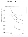
- Curves I, II and III represent 500 »m/0.49 N (500 »m/50 gf), 500 »m/0.29 N (500 »m/30 gf) and 250 »m/0.25 N (250 »m/25 gf), respectively, of a unimorph-type.
- the larger the work load (1/2 ⁇ F where ⁇ : displacement at the end tip of cantilever and F: generated force), the higher the effect of the Young's modulus relative to the reduction of the necessary strain. Namely, the larger the work load, the more advantageous it becomes to use a material having a high Young's modulus.
- Y2 the Young's modulus of the piezoelectric element
- Y1 the Young's modulus of the supporting member
- t2 the thickness of the piezoelectric element
- t1 the thickness of the supporting member
- F generated force
- ⁇ displacement at the end tip of cantilever
- l length of the piezoelectric element
- b width of the piezoelectric element.
- the thickness t2 of the piezoelectric element satisfies the following formula I
- the thickness t1 of the supporting member satisfies the formula I: 100 »m ⁇ t2 ⁇ 5000 »m Y 2 t2 »m ⁇ t1 ⁇ 2 ⁇ Y t2 »m
- Table 1 shows the shape of each piezoelectric actuator 100 or 200 and the conditions for the measurement.
- the unimorph-type piezoelectric actuator 100 was fixed at one end, and the displacement ⁇ at the end tip of cantilever and the generated force F at the other end were measured.
- the displacement ⁇ at the end tip of cantilever was measured by an eddy current system senser, and the generated force F was represented by the force whereby the displacement at the end tip of cantilever becomes 0.
- the bimorph-type piezoelectric actuator 200 was measured in the same manner as described above. The results thereby obtained are shown in Table 2.
- the Comparative Examples in Table 2 will be described as follows:
- the size of the piezoelectric element and the intensity of the applied electrical field were the same as in Example 1.
- a longitudinal effect-type laminated piezoelectric ceramic element was used and the supporting member was varied.
- the width of the element was 5 mm
- the length of the element was 15 mm
- the thickness of the supporting member was 60 »m
- the Young's modulus of the piezoelectric element was 5.9 x 10¹⁰ Pa (N/m2).
- d33 720 x 10 ⁇ 6 m/V)
- Y1 2.1 x 10¹¹ Pa (N/m2)
- Y1/Y2 3.6
- Applied electric field strength 1.35 MV/m (kV/mm)
- Figure 8 shows the relation between the applied electric field intensity and the displacement at the end tip of cantilever
- Figure 7 shows the relation between the displacement at the end tip of cantilever and the generated force.
- a longitudinal effect-type laminated piezoelectric element is formed by laminating piezoelectric ceramic sheets in their thickness direction, and a means for constraining the expansion of the element is provided on one side in the longitudinal direction of the longitudinal effect-type laminated piezoelectric element, whereby the longitudinal effect-type laminated piezoelectric element is used in a bending mode, and it is thereby possible to obtain a piezoelectric strain coefficient of from 2 to 3 times higher than the transversal effect-type piezelectric actuator of a unimorph-type.
- the bimorph-type piezoelectric actuator of the present invention has advantages over the conventional bimorph-type and multimorph-type transversal effect-type piezoelectric elements in that it is possible to apply the electric field in the same direction as the polarization direction of the piezoelectric ceramic sheets, whereby a relatively high electric field can be applied without leading to dielectric breakdown and without requiring a means for preventing depolarization, and accordingly it is possible to obtain a large displacement at the end tip of cantilever and a large generated force.
- the required intensity of the applied electric field can be substantially reduced by adjusting the Young's modulus Y2 and Y1 of the piezoelectric ceramic element and of the supporting member to be Y1 ⁇ 2.5 Y2, the thickness t2 of the piezoelectric element to be 100 »m ⁇ t2 ⁇ 5000 »m and the ratio of t1/t2 where t2 is the thickness of the piezoelectric element and t1 is the thickness of the supporting member, to be at least 1.6. Accordingly, the generated force and the displacement at the end tip of cantilever can be increased over the conventional levels.
- the thickness t2 of the piezoelectric ceramic element satisfies the following formula I and the thickness t1 of the supporting member satisfies the following formula II, it is possible to determine the combination of the thicknesses which minimizes the necessary intensity of the applied electric filed once the materials used and the desired displacement at the end tip of cantilever and generated force are determined, whereby it is possible to increase the generated force and the displacement at the end tip of cantilever: 100 »m ⁇ t2 ⁇ 5000 »m ⁇ Y 2 t2 »m ⁇ t1 ⁇ 2 ⁇ Y t2 »m
Description
- The present invention relates to a piezoelectric actuator which is capable of providing a large displacement at the end tip of cantilever and a large generated force.
- Figures 3 to 6 show conventional piezoelectric actuators.
- The embodiments according to Figures 3 to 6 are known from Ceramic Material for Electronics, p. 202-205 (edited by R. C. Buchanan).
- The embodiments according to Figures 3 to 5 are known from Proc. at the 33rd Annual National Relay Conference, Oklahoma (1985) p. 7-1.
- The embodiments according to Figures 5 and 6 are known from Proceedings of the sixth international meeting on ferrolectricity, Kobe 1985, JJAP 24 (1985) Supplement 24-2, p.457-459.
- The embodiment according to Figure 6 is known from JJAP 24 (1985) Supplement 24-2, p.485-487 and USP 4593160.
- Figure 3 is a perspective view of a longitudinal effect-type laminated piezoelectric actuator, wherein reference numeral 1 indicates the entire structure of a longitudinal effect-type laminated piezoelectric element (hereinafter referred to simply as a piezoelectric element 1),
numeral 2 indicates a piezoelectric ceramic sheet,numeral 3 indicates an electrode, andnumeral 4 indicates a power source, whereby an electric field E is applied to each piezoelectricceramic sheet 2 via theelectrode 3. Symbol P indicates the polarization direction of each piezoelectric ceramic sheet. Arrow A indicates the direction of contraction of the piezoelectricceramic sheet 2 upon the application of the electric field E, and arrow B indicates the direction of expansion of the piezoelectricceramic sheet 2. - Thus, the piezoelectric element 1 is composed of several hundred piezoelectric
ceramic sheets 2 each having a thickness of from 50 to 100 »m, laminated in their thickness direction and designed to utilize the longitudinal effect whereby the entire element expands in a longitudinal direction upon the application of the electric field E in the same direction as the polarization direction P. - Figure 4 is a perspective view of a transversal effect-type piezoelectric actuator which is referred to as a unimorph-type. In this Figure, the same reference symbols as used in Figure 3 indicate the same elements, and reference numeral 5 indicates a transversal effect-type piezoelectric element (hereinafter referred to simply as a piezoelectric element 5),
numeral 6 indicates a piezoelectric ceramic sheet, and numeral 11 is a bending metal plate bonded to one side of the piezoelectricceramic sheet 6 with the above-mentionedelectrode 3 interposed therebetween. - Thus, the piezoelectric element 5 is composed of a piezoelectric
ceramic sheet 6 having a thickness of from 100 to 500 »m and a metal plate 11 bonded to one side thereof, and it is of a type to be flexed in the direction of arrow C by the transversal effect whereby it expands in the thickness direction upon the application of the electric field E in the same direction as the polarization direction P of the piezoelectricceramic sheet 6. - Figure 5 is a perspective view of a transversal effect-type piezoelectric actuator which is referred to as a bimorph-type. In this Figure, the same reference symbols as in Figure 4 indicate the same elements, and
reference numerals numeral 8 indicates a transversal effect-type piezoelectric element (hereinafter referred to simply as a piezoelectric element 8), andnumeral 9 is a fixing means for fixing thepiezoelectric element 8. In this embodiment, thepiezoelectric element 8 is composed of piezoelectricceramic sheets ceramic sheet 6A in a direction opposite to the polarization direction P and to the other piezoelectricceramic sheet 6B in the same direction as the polarization direction P. - Figure 6 is a perspective view of a transversal effect-type laminated piezoelectric actuator which is referred to as a multimorph-type. In this Figure, the same reference symbols as in Figure 5 indicate the same elements, and
reference numeral 10 indicates a transversal effect-type laminated piezoelectric element of multimorph-type (hereinafter referred to simply as a piezoelectric element 10). - Thus, the
piezoelectric element 10 has a structure wherein a plurality, two each in the illustrated case, of piezoelectricceramic sheets piezoelectric element 6A′ at an upper portion above the center of thepiezoelectric element 10 in a direction opposite to the polarization direction P and to apiezoelectric element 6B′ at a lower portion in the same direction as the polarization direction P. - The conventional longitudinal effect-type laminated piezoelectric actuator as shown in Figure 3 has a problem such that the displacement δ at the end tip of cantilever is very small at a level of a few ten »m or less although the generated force F can be as large as a few GPa (a few hundred kg/mm²).
- On the other hand, the unimorph-type piezoelectric actuator as shown in Figure 4 is usually used as an oscillator for a piezoelectric buzzer, and the technique for designing such an oscillator has been almost fully established by now. However, in an application where no oscillation is utilized as in the case of an actuator or in a case where low frequency driving is conducted, no design has been disclosed to bring e.g. the thicknesses of the piezoelectric element and the bending supporting member to the optimum for obtaining a large displacement at the end tip of cantilever and a large generated force simultaneously.
- The bimorph-type piezoelectric acturator of a double layer structure (no intermediate sheet) as shown in Figure 5 is prepared usually by bonding a pair of piezoelectric ceramic sheets made of the same material and having the same size (and thickness). Also in this case, no product has been disclosed which is capable of providing a large displacement at the end tip of cantilever and a large generated force simultaneously.
- Namely, the transversal effect-type piezoelectric actuators as shown in Figures 4 to 6 are superior in the displacement at the end tip of cantilever by virtue of the bending mode as compared with the longitudinal effect-type piezoelectric actuators, and the displacement δ at the end tip of cantilever is as large as a few hundred »m, but the constraint generating force is conversely very small at a level of from 10⁻² ∼ 10⁻¹ N (a few gf to a few tens gf). In the case of the transversal effect-type piezoelectric actuators, the constraint force may be increased either by increasing the thickness of the piezoelectric
ceramic sheet 6 or by reducing the length of the piezoelectric element. However, there has been a problem that the displacement δ at the end tip of cantilever is inversely proportional to the thickness and decreases in proportion to the square of the length of the piezoelectric element. - More specifically, with respect to the bimorph-type as shown in Figure 5, the relations of the displacement δ at the end tip of cantilever and the constraint generated force F are represented by the following equations:


where ℓ: effective length of the piezoelectricceramic sheet 6, d₃₁: piezoelectric strain coefficient, E: electric field intensity, t: thickness per layer, b: width of the piezoelectricceramic sheet 6, and Y: Young's modulus. The applied voltage V = Et. - With respect to a multimorph-type as shown in Figure 6, the corresponding relations are represented by the following equations:


where N: number of laminated pairs, and other symbols are the same as in the equations (1) and (2). - Thus, it is possible to increase the displacement δ at the end tip of cantilever and the constraint generated force F simultaneously either by using a material having a large piezoelectric strain coefficient (d₃₁, d₃₃) or by intensifying the applied electric field.
- However, it is very difficult to find a new material having a high piezoelectric strain coefficient (d₃₁, d₃₃) since such an aspect has already been extensively explored by now.
- The bimorph-type has been devised since no adequate displacement δ at the end tip of cantilever and constraint generated force F have been obtained by the unimorph-type as shown in Figure 4 among the transversal effect-type piezoelectric actuators.
- However, in the case of the bimorph-type, it is necessary to apply the electric field E in a direction opposite to the polarization direction P, and the intensity of the electric field E is limited to a level at which no depolarization takes place. Namely, with the bimorph-type, the electric field E applicable is at a level of only 0.5 MV/m (500 V/mm) at best, while the allowable electric field E applied in the same direction as the polarization direction P is at a level of from 1 to 2 MV/m (kV/mm) (i.e. the level of the electric field at which no dielectric breakdown takes place). For this reason, even with the bimorph-type, it is difficult to obtain sufficiently large displacement δ at the end tip of cantilever and constraint generated force F simultaneously although the displacement at the end tip of cantilever and constraint generated force thereby obtainable are larger than those obtainable by the unimorph-type.
- It is an object of the present invention to solve the above-mentioned problems and to provide a piezoelectric actuator capable of providing a large displacement at the end tip of cantilever and a large force simultaneously by making it possible to apply a high intensity electric field to a piezoelectric ceramic element and whereby it is possible to reduce or minimize the electric field intensity required for such purpose.
- The present invention provides a piezoelectric actuator comprising a longitudinal effect-type laminated piezoelectric element composed of piezoelectric ceramic sheets laminated in their thickness direction, and a supporting member fixed to one side in the longitudinal direction of the element and being bending and capable of constraining expansion of the element.
- A piezoelectric actuator is preferred wherein the supporting member is fixed to the longitudinal effect-type piezoelectric element with an insulating layer interposed therebetween, when at least the surface of the supporting member is electrically conductive.
- Now, the present invention will be described in detail with reference to the preferred embodiments.
- In the accompanying drawings:
- Figure 1 is a perspective view of an embodiment of the present invention;
- Figure 2 is a perspective view of another embodiment of the present invention;
-
Fgiures 3 to 6 show conventional piezoelectric actuators, namely, Figure 3 is a perspective view of a longitudinal effect-type laminated piezoelectric actuator, and Figures 4, 5 and 6 are perspective views of unimorph-type, bimorph-type and multimorph-type transversal effect-type piezoelectric actuators, respectively; - Figure 7 shows the relation between the applied electric field intensity and the Young's modulus of supporting members in Examples of the present invention;
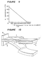
- Figure 8 shows the relation between the applied electric field intensity and the displacement at the end tip of cantilever as measured with respect to the unimorph-type actuator in Example 6;
- Figure 9 shows the relation between the displacement at the end tip of cantilever and the generated force as measured with respect to the unimorph-type actuator in Example 6; and
- Figure 10 illustrates a construction wherein two unimorph-type elements are combined to make the forward end portion horizontal.
- In the piezoelectric actuator of the present invention, a supporting member made of a non-piezoelectric bending plate capable of constraining expansion or contraction of a longitudinal effect-type laminated piezoelectric element or a supporting member made of a transversal effect-type piezoelectric element contractible in a direction opposite to the direction of expansion of the longitudinal effect-type laminated piezoelectric element, is fixed to one side in the longitudinal direction of the longitudinal effect-type laminated piezoelectric element composed of piezoelectric ceramic sheets laminated in their thickness direction. It is preferred in the case of the unimorph-type actuator that the Young's modulus of the supporting member is at least 2.5 times the Young's modulus of the piezoelectric element; the thickness t₂ of the piezoelectric element is within a range of 100 »m ≦ t₂ ≦ 5000 »m; and the ratio of t₂/t₁ where t₂ is the thickness of the piezoelectric element and t₁ is the thickness of the supporting member, is at least 1.6.
- More preferably, the thickness t₂ of the piezoelectric elemnt and the thickness t₁ of the supporting member satisfy the following formulas I and II, repectively:


where Y = Y₂/Y₁ where Y₂ is the Young's modulus of the piezoelectric element and Y₁ is the Young's modulus of the supporting member. - Now, the present invention will be described in more detail with reference to the drawings.
- Figure 1 is a perspective view of a unimorph-type piezoelectric actuator as an embodiment of the present invention, wherein the same reference symbols as used in Figure 3 indicate the same elements, and
reference numeral 100 indicates the unimorph-type piezoelectric actuator, which is a combination of a longitudinal effect-type laminated piezoelectric element 1 (hereinafter referred to simply as a piezoelectric element 1) and a metal plate 11. Namely, the metal plate 11 is bonded to one side in the longitudinal direction of the piezoelectric element 1 (composed of a number of piezoelectric ceramic sheets laminated in their thickness direction in the same manner as illustrated in Figure 3 and laid in the direction of lamination) by an insulating adhesive such as an epoxy resin to form aninsulating layer 12. Although not shown in Figure 1, the direction for the application of the electric field E, the polarization direction P, the contraction direction A and the expansion direction B are the same as in the case of the piezoelectric element 1 in Figure 3. - Figure 2 is a perspective view of a bimorph-type piezoelectric actuator as another embodiment of the present invention, wherein the same reference symbols as in Figure 1 indicate the same elements, and
reference numeral 200 is the bimorph-type piezoelectric actuator, which is a combination of a longitudinal effect-type piezoelectric element 1 and a transversal effect-type laminatedpiezoelectric element 6B′ (hereinafter referred to simply as apiezoelectric element 6B′). - Although not shown in the Figure, the direction of the application of the electric field E, the polarization direction P, the contraction direction A and the expansion direction B are the same as in Figure 3 with respect to the piezoelectric element 1 and are the same as in the case of the multimorph-type
piezoelectric element 6B′ shown in Figure 6 with respect to thepiezoelectric element 6B′ . A metal plate 11 as shown in Figure 1 may be interposed between theinsulating layer 12 and thepiezoelectric element 6B′. - Now, for the preparation of the
piezoelectric actuators electrode 3 is formed by screen printing. A plurality of the piezoelectric ceramic sheets thus prepared are laminated and press-bonded under heating to obtain a monolithic shaped product. The thickness of each piezoelectricceramic sheet 2 and the number of laminated sheets correspond to the length of the piezoelectric element 1 and they are determined to obtain a necessary length of the element taking into the consideration the desired applied voltage, displacement at the end tip of cantilever, generated force, etc. The shaped product is then cut in a direction perpendicular to the direction of theelectrodes 3 so that the thickness of the piezoelectric element 1 would be about from a few hundred »m to a few thousand »m and then sintered and subjected to necessary abrasive finishing to obtain a finished element composed of piezoelectricceramic sheets 2 laminated in the longitudinal direction of the element. - Otherwise, the shaped product may be sintered as it is i.e. without cutting, and then, cut and subjected to abrasive finishing to obtain a piezoelectric element 1 in a similar fashion. To this, outer connecting electrodes are fixed with inner electrodes and a lead wire is connected thereto, followed by polarization treatment.
- Then, in the case of the unimorph-
type piezoelectric actuator 100 as shown in Figure 1, an epoxy resin serving both as an insulating agent and as an adhesive is coated on a metal plate 11 made of e.g. a Fe-Ni alloy to form an insulatinglayer 12, and then, the metal plate 11 is bonded to the piezoelectric element 1. - In the case of the bimorph-
type piezoelectric actuator 200 as shown in Figure s, a transversal effect-type laminatedpiezoelectric element 6B′ is sintered, then processed into a predetermined shape and subjected to polarization treatment, and thereafter an insulatinglayer 12 is formed in the same manner as in the case of the unimorph-type of Figure 1. Then, theelement 6B′ is bonded to the piezoelectric element 1. Further, in order to facilitate the leading out of the electrodes, a bending metal plate may be inserted as an intermediate electrode plate between the transversal effect-type laminatedpiezoelectric element 6B′ and the insulatinglayer 12 and simultaneously bonded. - In the
piezoelectric actuator 200, a single layer transversal effect-type piezoelectric element 6B may be provided instead of the transversal effect-type laminatedpiezoelectric element 6B′ to obtain the same function and effects. - Although not shown in the Figure, the direction of the application of the electric field E, the polarization direction P, the contraction direction A and the expansion direction B are the same as in the case of the piezoelectric element 1 in Figure 3.
- The longitudinal effect-type piezoelectric element 1 of a plate form thus prepared by the above steps is applied to a bending mode to obtain a unimorph-type or bimorph-
type piezoelectric actuator - Thus, when the above piezoelectric element 1 is used for the unimorph-
type piezoelectric actuator 100, the piezoelectric strain will be from 2 to 3 times greater than the conventional unimorph-type piezoelectric element 5 (i.e. d₃₃ ≒ 2 to 3 x d₃₁). Accordingly, the displacement δ at the end tip of cantilever and the generated force F will be from 2 to 3 times larger than the conventional transversal effect-type unimorph of the same shape. - On the other hand, when it is used for the bimorph-
type piezoelectric actuator 200, the upper portion above the insulatinglayer 12 expands by means of the longitudinal effect-type piezoelectric element 1, and the lower portion below the insulatinglayer 12 contracts by means of the transversal effect-type piezoelectric element 6B′. By using this combination, it is possible to apply the electric field E to thepiezoelectric elements 1 and 6B′ in the same direction as the polarizing direction P, whereby depolarization which used to be a drawback of the conventional bimorph-type does not take place, and it is possible to apply the electric field with high intensity at a level where no substantial dielectric breakdown takes place. - Accordingly, it is unnecessary to apply a low electric field to each of the two piezoelectric elements in order to avoid the depolarization which used to be the most serious drawback of the conventional bimorph-type, or to take a trouble of preventing the depolarization by applying a high electric field in the same direction and a low electric field in the opposite direction. Namely, in the case of the conventional bimorph-type, the electric field applicable in the direction opposite to the polarization direction is at a level of only 0.5 MV/m (500 V/mm) at best. Whereas, when the
piezoelectric actuator - Further, since a longitudinal effect-type piezoelectric element 1 is used in the same manner as in the unimorph-type, the piezoelectric strain will be from about 2 to about 3 times larger even when the same material as the conventional material is used (d₃₃ ≒ 2 to 3 x d₃₁). Thus, it is possible not only to apply an electric field E higher by from 2 to 10 times than the conventional actuator but also to utilize a piezoelectric strain larger by from 2 to 3 times, whereby both the displacement δ at the end tip of cantilever and the generated force F can be increased by from 4 to 30 times.
- The supporting member is required to have a sufficient strength to constrain the expansion of the piezoelectric ceramic element and at the same time required to be bending. Further, when the supporting member is an electrically conductive material or a transversal effect-type piezoelectric ceramic material, it is necessary to interpose an insulating layer between it and the longitudinal effect-type piezoelectric element since electrodes are exposed on the surface of the longitudinal effect-type piezoelectric element. More specifically, the supporting member may be made of an oxide ceramic material such as alumina, zirconia, MgAl₂O₄, mullite, beryllia or cordierite; a non-oxide ceramic material such as SiC, Si₃N₄, AlN, B₄C, TiC or tungsten carbide; a metal plate such as an iron-nickel alloy; or a transversal effect-type piezoelectric ceramic element.
- Further, it has been found possible to substantially reduce the required intensity of the electric field by adjusting the Young's modulus of the supporting member to a level of at least 2.5 times the Young's modulus of the piezoelectric element 1 to which it is bonded, the thickness t₂ of the piezoelectric element 1 within a range of 100 »m ≦ t₂ ≦ 5000 »m and the ratio of t₂/t₁ where t₂ is the thickness of the piezoelectric element and t₁ is the thickness of the supporting member, to a level of at least 1.6. Namely, the Young's modulus of the two members preferably satisfy Y₁ ≧ 2.5 Y₂ where Y₁ is the Young's modulus of the supporting member and Y₂ is the Young's modulus of the piezoelectric element. If the Young's modulus of the supporting member is less than 2.5 times the Young's modulus of the piezoelectric element, the reduction of the required intensity of the applied electric field is small. If the ratio in the thickness of the piezoelectric element to the supporting member is less than 1.6, not only the reduction in the required strength of the applied electric field decreases, but also a higher intensity of the applied electric fi-eld will be required because a supporting member having a high Young's modulus will be employed, such being disadvantageous.
- In Figure 7, the relation between the Young's modulus Y₁ (x 10¹⁰ Pa (N/m²)) of the supporting member and the electric field strength (MV/m) (kV/mm) for the desired displacement at the end tip of cantilever and generated force. The Young's modulus Y₂ of the piezoelectric element 1 was set to be Y₂ = 5.9 x 10¹⁰ Pa (N/m²), and the thickness of the supporting member was 60 »m, the thickness of the piezoelectric element was 210 »m (i.e. the ratio to the thickness is 3.5), the width of the piezoelectric element was 5 mm and the length of the piezoelectric element was 15 mm.
- Curves I, II and III represent 500 »m/0.49 N (500 »m/50 gf), 500 »m/0.29 N (500 »m/30 gf) and 250 »m/0.25 N (250 »m/25 gf), respectively, of a unimorph-type.
- As is evident from this Figure, when a supporting member 11 made of a material having a large Young's modulus Y₁, the prescribed levels of the displacement at the end tip of cantilever and the force can be obtained with a small level of the required strain (d x E, where d: piezoelectric strain coefficient, and E: electric field).
- Thus, if an electric field higher than this is applied, a larger generated force and displacement at the end tip of cantilever can be obtained.
- Further, the larger the work load (1/2 δF where δ: displacement at the end tip of cantilever and F: generated force), the higher the effect of the Young's modulus relative to the reduction of the necessary strain. Namely, the larger the work load, the more advantageous it becomes to use a material having a high Young's modulus.
- Further, it has been found that the optimum combination of the thicknesses to minimize the required intensity of the applied electric field is as follows. Namely, Y = Y₂/Y₁ and n = t₂/t₁, where Y₂ is the Young's modulus of the piezoelectric element, Y₁ is the Young's modulus of the supporting member, t₂ is the thickness of the piezoelectric element and t₁ is the thickness of the supporting member. It has been found that the intensity of the applied electric field may be the minimum when the relation of the two is


where F: generated force, δ: displacement at the end tip of cantilever, ℓ: length of the piezoelectric element, and b: width of the piezoelectric element. The influence of the electrodes or the adhesive layer is negligible since their thicknesses are usually very thin as compared with the thicknesses of the piezoelectric element and the supporting member. - Thus, a larger generated force and displacement at the end tip of cantilever can be obtained if it is possible to apply an electric field of a higher intensity.
- The above conditions for t₁ and t₂ are the optimum. However, usually it is sufficient that the thickness t₂ of the piezoelectric element satisfies the following formula I, and the thickness t₁ of the supporting member satisfies the formula I:


- Now, specific shapes of the
piezoelectric actuators - Table 1 shows the shape of each
piezoelectric actuator - In reference to Table 1, the unimorph-
type piezoelectric actuator 100 was fixed at one end, and the displacement δ at the end tip of cantilever and the generated force F at the other end were measured. - The displacement δ at the end tip of cantilever was measured by an eddy current system senser, and the generated force F was represented by the force whereby the displacement at the end tip of cantilever becomes 0.
- The bimorph-
type piezoelectric actuator 200 was measured in the same manner as described above. The results thereby obtained are shown in Table 2. The Comparative Examples in Table 2 will be described as follows: - The size of the piezoelectric element and the intensity of the applied electrical field were the same as in Example 1. However, as the piezoelectric element, instead of the longitudinal effect-type laminated element, a transversal effect-type element having the same length was used (d₃₁ = 260 x 10⁻¹² m/V).
- The size of the piezoelectric element was the same as in Example 2. However, as the piezoelectric element, instead of the longitudinal effect-type laminated element, a transversal effect-type element having the same thickness was used (d₃₁ = 260 x 10⁻¹² m/V). The intensity of the applied electric field was 1 MV/m (kV/mm) in the same direction as the polarization direction and 0.4 kV/mm in the opposite direction.


- In each of the following Examples, a longitudinal effect-type laminated piezoelectric ceramic element was used and the supporting member was varied. The width of the element was 5 mm, the length of the element was 15 mm, the thickness of the supporting member was 60 »m and the Young's modulus of the piezoelectric element was 5.9 x 10¹⁰ Pa (N/m²).
- As Comparative Examples, there will be given a case wherein phosphor bronze was used as the supporting member to show an embodiment where Y₁/Y₂ < 2.5 and a case wherein the ratio of the thicknesses of the piezoelectric element and the supporting member is less than 1.6. The size of the element and the piezoelectric elements used were the same as in the Examples.
- Supporting member: zirconia (t₁ = 60 »m)
Piezoelectric element: PZT ceramics (t₂ = 210 »m) (d₃₃ = 720 x 10⁻⁶ m/V)
(Y₁ = 2.1 x 10¹¹ Pa (N/m²)), Y₁/Y₂ = 3.6
Applied electric field strength: 1.35 MV/m (kV/mm)
Measured values: Displacement at the end tip of cantilever: 560 »m
Generated force: 0.46 N (47 gf) - Supporting member: alumina (t₁ = 60 »m)
Piezoelectric element: PZT ceramic element (t₂ = 210 »m)
(d₃₃ = 720 x 10⁻¹² m/V)
(Y₁ = 3.3 x 10¹¹ Pa (N/m²)), Y₁/Y₂ = 5.6
Applied electric field intensity: 1.20 MV/m (kV/mm)
Measured values: Displacement at the end tip of cantilever: 550 »m
Generated force: 0.47 N (48 gf) - Supporting member: tungsten carbide (t₁ = 60 »m)
Piezoelectric element: PZT ceramic element (t₂ = 210 »m)
(Y₁ = 6.9 x 10¹¹ Pa (N/m²)), Y₁/Y₂ = 11.7
Applied electric field intensity: 1.10 MV/m (kV/mm)
Measured values: Displacement at the end tip of cantilever: 560 »m
Generated force: 0.48 N (49 gf)
Piezoelectric strain coefficient d₃₃ = 720 x 10⁻¹² m/V
Piezoelectric strain coefficient d₃₁ = 260 x 10⁻¹² m/V - Supporting member: phosphor bronze (t₁ = 60 »m)
Piezoelectric element: PZT ceramic element (t₂ = 210 »m)
(Y₁ = 1.2 x 10¹¹ Pa (N/m²)), Y₁/Y₂ = 2.0
Applied electric field intensity: 1.54 MV/m (kV/mm)
Thickness of the supporting member, and thickness of the piezoelectric element: same as in the Examples
Measured values: Displacement at the end tip of cantilever: 510 »m
Generated force: 0.44 N (45 gf) - It is evident in each of the Examples of the present invention, large displacement at the end tip of cantilever and generated force are obtainable with a low intensity of the applied electric field as compared with the Comparative Example.
- Supporting members: alumina (Y₁ = 3.3 x 10¹¹ Pa (N/m²))
Piezoelectric element: PZT ceramic element (Y₂ = 5.9 x 10¹⁰ Pa (N/m²))
Thickness of the supporting member: 140 »m (Y₁/Y₂ = 5.6)
Thickness of the piezoelectric element: 140 »m (t₂/t₁ = 1.0)
Applied electric field intensity: 1.70 MV/m (kV/mm)
Measured values: Displacement at the end tip of cantilever: 520 »m
Generated force: 0.45 N (46 gf) - It is evident that in this Comparative Example, an electric field intensity higher than Example 3 wherein zirconia having a Young's Modulus lower than alumina is used, is required, and not only that, an electric field intensity higher than Comparative Example 3 wherein phosphor bronze is used, is required, such being disadvantageous.
- Type: Unimorph
Supporting member: alumina
Piezoelectric element: PZT ceramic element (d₃₃ = 720 x 10⁻² m/V)
m: 0.1778 [(Y₂ = 5.9 x 10¹⁰ Pa (N/m²))/(Y₁ = 3.3 x 10¹¹ Pa (N/m²))]
n: 2.365 [(t₂ = 200 »m)/(t₁ = 85 »m)]
Applied electric field intensity: 1.17 MV/m (kV/mm)
Measured values: Displacement at the end tip of cantilever: 550 »m
Generated force: 0.47 N (48 gf) - Further, Figure 8 shows the relation between the applied electric field intensity and the displacement at the end tip of cantilever, and Figure 7 shows the relation between the displacement at the end tip of cantilever and the generated force.
- Type: Unimorph
Supporting member: zirconia
Piezoelectric element: PZT ceramic element (d₃₃ = 720 x 10⁻¹² m/V)
Y: 0.2810 [(Y₂ = 5.9 x 10¹⁰ Pa (N/m²))/(Y₁ = 2.1 x 10¹¹ Pa (N/m²))]
n: 1.887 [(t₂ = 195 »m)/(t₁ = 104 »m)]
Applied electric field intensity: 1.25 MV/m (kV/mm)
Measured values: Displacement at the end tip of cantilever: 560 »m
Generated force: 0.46 N (47 gf)
Piezoelectric coefficient: d₃₃ = 720 x 10⁻¹² m/V - Type: Bimorph
Supporting member: transversal effect-type piezoelectric element: PZT ceramic element (d₃₁ = 260 x 10⁻¹² m/V)
Piezoelectric element: PZT ceramic element (d₃₃ = 720 x 10⁻¹² m/V)
Y: 0.8806 [(Y₂ = 5.9 x 10¹⁰ Pa (N/m²))/(Y₁ = 6.7 x 10¹⁰ Pa (N/m²))]
n: 1.066 [(t₂ = 180 »m)/(t₁ = 170 »m)]
Applied electric field intensity: 1.10 MV/m (kV/mm)
Measured values: Displacement at the end tip of cantilever: 580 »m
Generated force: 0.46 N (47 gf) - (Same combination of the materials as in Example 6 except that t₁ does not satisfy the formula II)
- Type: Unimorph
Supporting member: alumina
Piezoelectric element: PZT ceramic element
Y: 0.1788 (same as in Example 6)
n: 1.0 [(t₂ = 140 »m)/(t₁ = 140 »m)]
Applied electric field intensity: 1.70 MV/m (kV/mm)
Measured values: Displacement at the end tip of cantilever: 520 »m
Generated force: 0.45 N (46 gf) - It is evident from the foregoing that in each Example of the present invention, a large displacement at the end tip of cantilever and a large generated force are obtainable with a low applied electric field intensity as compared with the Comparative Examples.
- As the displacement at the end tip of cantilever increases, the forward end portion of cantilever will deflect from the horizontal position. If such deflection is undesirable, it is possible to maintain the forward end portion to be horizontal by arranging two
piezoelectric elements 7 against a supporting member 11 as shown in Figure 10, so that the displacement directions are opposed to each other, whereby the positions after the displacement are as shown by dotted lines. - As described in the foregoing, according to the present invention, a longitudinal effect-type laminated piezoelectric element is formed by laminating piezoelectric ceramic sheets in their thickness direction, and a means for constraining the expansion of the element is provided on one side in the longitudinal direction of the longitudinal effect-type laminated piezoelectric element, whereby the longitudinal effect-type laminated piezoelectric element is used in a bending mode, and it is thereby possible to obtain a piezoelectric strain coefficient of from 2 to 3 times higher than the transversal effect-type piezelectric actuator of a unimorph-type. Further, the bimorph-type piezoelectric actuator of the present invention has advantages over the conventional bimorph-type and multimorph-type transversal effect-type piezoelectric elements in that it is possible to apply the electric field in the same direction as the polarization direction of the piezoelectric ceramic sheets, whereby a relatively high electric field can be applied without leading to dielectric breakdown and without requiring a means for preventing depolarization, and accordingly it is possible to obtain a large displacement at the end tip of cantilever and a large generated force.
- Furthermore, the required intensity of the applied electric field can be substantially reduced by adjusting the Young's modulus Y₂ and Y₁ of the piezoelectric ceramic element and of the supporting member to be Y₁ ≦ 2.5 Y₂, the thickness t₂ of the piezoelectric element to be 100 »m ≦ t₂ ≦ 5000 »m and the ratio of t₁/t₂ where t₂ is the thickness of the piezoelectric element and t₁ is the thickness of the supporting member, to be at least 1.6. Accordingly, the generated force and the displacement at the end tip of cantilever can be increased over the conventional levels.
- Still further, when the thickness t₂ of the piezoelectric ceramic element satisfies the following formula I and the thickness t₁ of the supporting member satisfies the following formula II, it is possible to determine the combination of the thicknesses which minimizes the necessary intensity of the applied electric filed once the materials used and the desired displacement at the end tip of cantilever and generated force are determined, whereby it is possible to increase the generated force and the displacement at the end tip of cantilever:


Claims (6)
- Piezoelectric bimorph-type actuator (200) comprising a longitudinal effect-type laminated piezoelectric element (1) composed of piezoelectric ceramic sheets (2) laminated in their thickness direction, and a supporting member (6B′) fixed to one side along the direction of displacement of said longitudinal piezoelectric electric element caused by a longitudinal effect, said supporting member (6B′) being a transversal effect-type piezoelectric element bendable and capable of constraining expansion of the longitudinal effect-type laminated piezoelectric element (1) in a direction opposite to the direction of expansion of said longitudinal effect-type laminated piezoelectric element, and an insulating layer (12) interposed between said piezoelectric element (1) and said supporting member (6B′).
- Piezoelectric unimorph-type actuator (100) comprising a longitudinal effect-type laminated piezoelectric element (1) composed of piezoelectric ceramic sheets (2) laminated in their thickness direction, and a supporting member (11) fixed to one side along the direction of displacement of said longitudinal piezoelectric element caused by a longitudinal effect, said supporting member (11) being a non-piezoelectric bending plate capable of constraining expansion or contraction of the longitudinal effect-type laminated piezoelectric element (1), and an insulating layer (12) interposed between said piezoelectric element (1) and said supporting member (11), wherein the Young's modulus of the supporting member is at least 2,5 times the Young's modulus of the piezoelectric element; the thickness t₂ of the piezoelectric element is within a range of 100 mm ≦ t₂ ≦ 5000 »m; and the ratio of t₂/t₁ where t₂ is the thickness of the piezoelectric element (1) and t₁ is the thickness of the supporting member (11), is at least 1,6.
- The piezoelectric actuator according to claim 1 or claim 2, wherein the thickness t₂ of the piezoelectric element and the thickness t₁ of the supporting member (6B′, 11) satisfy the following formulas I and II, respectively:


- The piezoelectric actuator according to claim 2, wherein the supporting member (11) is made of a material selected from the group consisting of aluminia, zirconia, magnesium aluminate, beryllia, mullite, cordierite, tungsten carbide, titanium carbide, boron carbide, silicon carbide, silicon nitride, aluminium nitride and an iron-nickel alloy.
- The piezoelectric actuator according to claim 1 or claim 2, wherein the piezoelectric element (1) is made of a ceramic composition containing Pb, Zr and Ti.
- The piezoelectric actuator according to claim 1, wherein a metal plate (11) is interposed between the insulating layer (12) and the supporting member (6B′).
Applications Claiming Priority (6)
| Application Number | Priority Date | Filing Date | Title |
|---|---|---|---|
| JP228426/86 | 1986-09-29 | ||
| JP61228426A JP2533861B2 (en) | 1986-09-29 | 1986-09-29 | Piezoelectric actuator |
| JP30918986 | 1986-12-27 | ||
| JP309190/86 | 1986-12-27 | ||
| JP30919086 | 1986-12-27 | ||
| JP309189/86 | 1986-12-27 |
Publications (3)
| Publication Number | Publication Date |
|---|---|
| EP0262637A2 EP0262637A2 (en) | 1988-04-06 |
| EP0262637A3 EP0262637A3 (en) | 1990-01-03 |
| EP0262637B1 true EP0262637B1 (en) | 1995-03-22 |
Family
ID=27331402
Family Applications (1)
| Application Number | Title | Priority Date | Filing Date |
|---|---|---|---|
| EP87114140A Expired - Lifetime EP0262637B1 (en) | 1986-09-29 | 1987-09-28 | Piezoelectric actuator |
Country Status (3)
| Country | Link |
|---|---|
| US (2) | US4812698A (en) |
| EP (1) | EP0262637B1 (en) |
| DE (1) | DE3751183T2 (en) |
Families Citing this family (86)
| Publication number | Priority date | Publication date | Assignee | Title |
|---|---|---|---|---|
| EP0262637B1 (en) * | 1986-09-29 | 1995-03-22 | Mitsubishi Chemical Corporation | Piezoelectric actuator |
| US4928030A (en) * | 1988-09-30 | 1990-05-22 | Rockwell International Corporation | Piezoelectric actuator |
| JPH02138501A (en) * | 1988-11-17 | 1990-05-28 | Smc Corp | Nozzle flapper mechanism |
| JPH0733087B2 (en) * | 1989-06-09 | 1995-04-12 | シャープ株式会社 | Inkjet printer |
| DE69026765T2 (en) | 1989-07-11 | 1996-10-24 | Ngk Insulators Ltd | Piezoelectric / electrostrictive actuator containing a piezoelectric / electrostrictive film |
| JP2886588B2 (en) * | 1989-07-11 | 1999-04-26 | 日本碍子株式会社 | Piezoelectric / electrostrictive actuator |
| JP2867437B2 (en) * | 1989-07-19 | 1999-03-08 | ブラザー工業株式会社 | Piezoelectric inkjet printer head |
| JP3041952B2 (en) * | 1990-02-23 | 2000-05-15 | セイコーエプソン株式会社 | Ink jet recording head, piezoelectric vibrator, and method of manufacturing these |
| US6186619B1 (en) | 1990-02-23 | 2001-02-13 | Seiko Epson Corporation | Drop-on-demand ink-jet printing head |
| US5402159A (en) * | 1990-03-26 | 1995-03-28 | Brother Kogyo Kabushiki Kaisha | Piezoelectric ink jet printer using laminated piezoelectric actuator |
| JP2891510B2 (en) * | 1990-05-09 | 1999-05-17 | 日本電子株式会社 | Piezoelectric element driver |
| US5210455A (en) * | 1990-07-26 | 1993-05-11 | Ngk Insulators, Ltd. | Piezoelectric/electrostrictive actuator having ceramic substrate having recess defining thin-walled portion |
| US5363131A (en) * | 1990-10-05 | 1994-11-08 | Seiko Epson Corporation | Ink jet recording head |
| JP3185226B2 (en) * | 1991-01-30 | 2001-07-09 | 株式会社村田製作所 | Driving method of piezoelectric bimorph element and piezoelectric bimorph element |
| JP3198355B2 (en) * | 1991-05-28 | 2001-08-13 | キヤノン株式会社 | Small displacement element, scanning tunnel microscope using the same, and information processing apparatus |
| DE69223096T2 (en) * | 1991-07-18 | 1998-05-28 | Ngk Insulators Ltd | Piezoelectric / electrostrictive element with a ceramic substrate made of stabilized zirconium dioxide |
| US5247222A (en) * | 1991-11-04 | 1993-09-21 | Engle Craig D | Constrained shear mode modulator |
| US5350966A (en) * | 1991-11-12 | 1994-09-27 | Rockwell International Corporation | Piezocellular propulsion |
| JPH05218517A (en) * | 1992-02-06 | 1993-08-27 | Murata Mfg Co Ltd | Piezoelectric bimolph type actuator |
| US5268611A (en) * | 1992-03-16 | 1993-12-07 | Rockwell International Corporation | Anisotropic transducer |
| US6050679A (en) * | 1992-08-27 | 2000-04-18 | Hitachi Koki Imaging Solutions, Inc. | Ink jet printer transducer array with stacked or single flat plate element |
| US5493615A (en) * | 1993-05-26 | 1996-02-20 | Noise Cancellation Technologies | Piezoelectric driven flow modulator |
| GB9317294D0 (en) * | 1993-08-19 | 1993-10-20 | Westland Helicopters | Circulation control aerofoils |
| FR2710877B1 (en) * | 1993-10-07 | 1997-05-09 | Seiko Epson Corp | Ink jet recording head piezoelectric member, and method of manufacturing the same. |
| DE4337265C1 (en) * | 1993-11-02 | 1995-03-09 | Mayer Textilmaschf | Warp-knitting machine with at least one guide bar |
| US5378382A (en) * | 1993-12-09 | 1995-01-03 | Mitsubishi Kasei Corporation | Piezoelectric ceramic composition for actuator |
| US6781285B1 (en) * | 1994-01-27 | 2004-08-24 | Cymer, Inc. | Packaged strain actuator |
| US5626312A (en) * | 1994-07-06 | 1997-05-06 | Mcdonnell Douglas Corporation | Piezoelectric actuator |
| JPH09205781A (en) * | 1995-02-01 | 1997-08-05 | Seiko Epson Corp | Piezoelectric generator, and portable power supplier equipped with the same, and portable electronic equipment |
| EP0768532B1 (en) * | 1995-10-09 | 2003-04-23 | Matsushita Electric Industrial Co., Ltd | Acceleration sensor and method for producing the same, and shock detecting device using the same |
| JP3432974B2 (en) * | 1995-10-13 | 2003-08-04 | 日本碍子株式会社 | Piezoelectric / electrostrictive film type element |
| JPH09261978A (en) * | 1996-03-25 | 1997-10-03 | Nippon Cement Co Ltd | Laminated element and vibration driver |
| DE69735411T2 (en) * | 1996-10-09 | 2006-09-07 | Symyx Technologies, Inc., Santa Clara | INFRARED SPECTROSCOPY AND LIBRARY IMAGING |
| WO1998024296A2 (en) * | 1996-11-20 | 1998-06-11 | The Regents Of The University Of California | Multilaminate piezoelectric high voltage stack |
| DE19704389C2 (en) * | 1997-02-06 | 1999-02-04 | Fraunhofer Ges Forschung | Single element actuator |
| US5992032A (en) * | 1997-02-24 | 1999-11-30 | Chung-Shan Institute Of Science & Technology | Method and apparatus for inclination measurement using piezoelectric effect |
| GB9704769D0 (en) * | 1997-03-07 | 1997-04-23 | Powerbreaker Plc | Low component count release mechanism |
| DE19712034A1 (en) * | 1997-03-21 | 1998-09-24 | Deutsch Zentr Luft & Raumfahrt | Flexible leading edge profile for aerofoil |
| JP3456380B2 (en) * | 1997-09-02 | 2003-10-14 | 株式会社村田製作所 | Piezo actuator |
| JPH11168246A (en) * | 1997-09-30 | 1999-06-22 | Matsushita Electric Ind Co Ltd | Piezoelectric actuator, infrared ray sensor, and piezoelectric light deflector |
| US6393895B1 (en) | 1997-10-08 | 2002-05-28 | Symyx Technologies, Inc. | Method and apparatus for characterizing materials by using a mechanical resonator |
| US6494079B1 (en) * | 2001-03-07 | 2002-12-17 | Symyx Technologies, Inc. | Method and apparatus for characterizing materials by using a mechanical resonator |
| DE19745468C1 (en) * | 1997-10-15 | 1999-04-15 | Daimler Chrysler Ag | Piezoelectric actuator |
| JP4578596B2 (en) * | 1998-09-18 | 2010-11-10 | セイコーインスツル株式会社 | Vibrator, piezoelectric actuator, and electronic device using them |
| US6135713A (en) * | 1999-01-19 | 2000-10-24 | The Mcdonnell Douglas Helicopter Company | Helicopter rotor blade flap actuator government interest |
| US6329741B1 (en) * | 1999-04-30 | 2001-12-11 | The Trustees Of Princeton University | Multilayer ceramic piezoelectric laminates with zinc oxide conductors |
| JP2000332313A (en) * | 1999-05-21 | 2000-11-30 | Matsushita Electric Ind Co Ltd | Thin film piezoelectric bimorph element and application thereof |
| US6512323B2 (en) * | 2000-03-22 | 2003-01-28 | Caterpillar Inc. | Piezoelectric actuator device |
| DE10031877C1 (en) * | 2000-06-30 | 2001-12-20 | Fraunhofer Ges Forschung | Piezoelectric deflection device for optical rays e.g. beam scanner, has end region of piezoelectric plate provided with highly reflective coating for reflection of incident beam |
| US7248444B1 (en) * | 2000-07-21 | 2007-07-24 | Lauer Mark A | Electromagnetic heads, flexures, gimbals and actuators formed on and from a wafer substrate |
| US7302830B2 (en) | 2001-06-06 | 2007-12-04 | Symyx Technologies, Inc. | Flow detectors having mechanical oscillators, and use thereof in flow characterization systems |
| DE10329028A1 (en) * | 2002-07-11 | 2004-01-29 | Ceram Tec Ag Innovative Ceramic Engineering | Preparation of piezoelectric multi layer actuators for e.g. injection valves, provided with heat insulation formed by sintering thick coating mixture of inorganic material and organic binder |
| DE10234987A1 (en) * | 2002-07-31 | 2004-02-19 | Siemens Ag | Piezoelectric bending transducer |
| US7043969B2 (en) * | 2002-10-18 | 2006-05-16 | Symyx Technologies, Inc. | Machine fluid sensor and method |
| WO2004036207A2 (en) | 2002-10-18 | 2004-04-29 | Symyx Technologies, Inc. | Environmental control system fluid sensing system and method comprising a sesnsor with a mechanical resonator |
| US7089635B2 (en) * | 2003-02-25 | 2006-08-15 | Palo Alto Research Center, Incorporated | Methods to make piezoelectric ceramic thick film arrays and elements |
| US6895645B2 (en) * | 2003-02-25 | 2005-05-24 | Palo Alto Research Center Incorporated | Methods to make bimorph MEMS devices |
| DE602004013753D1 (en) * | 2003-03-21 | 2008-06-26 | Hella Kgaa Hueck & Co | RESONATOR SENSOR UNIT |
| US7721590B2 (en) * | 2003-03-21 | 2010-05-25 | MEAS France | Resonator sensor assembly |
| EP1644717A2 (en) * | 2003-03-21 | 2006-04-12 | Symyx Technologies, Inc. | Mechanical resonator |
| DE102004025603A1 (en) * | 2004-05-25 | 2005-12-22 | Forschungszentrum Karlsruhe Gmbh | Actuator based on geometrically anisotropic nanoparticles |
| DE202005014561U1 (en) * | 2005-09-15 | 2005-12-15 | Festo Ag & Co. | Piezoelectric bending transducer for use in piezoelectric valve, has supporting body exhibiting coefficient of elasticity greater than specified Pascal and specified thermal coefficient of expansion by utilization of carbon-fiber |
| DE102005060779B4 (en) * | 2005-12-16 | 2008-07-10 | Eads Deutschland Gmbh | power generator |
| DE102005061751B4 (en) | 2005-12-21 | 2013-09-19 | Eurocopter Deutschland Gmbh | Rotor blade for a rotary wing aircraft |
| US8780053B2 (en) * | 2007-03-21 | 2014-07-15 | Northwestern University | Vibrating substrate for haptic interface |
| US8405618B2 (en) | 2006-03-24 | 2013-03-26 | Northwestern University | Haptic device with indirect haptic feedback |
| US8525778B2 (en) * | 2007-03-21 | 2013-09-03 | Northwestern University | Haptic device with controlled traction forces |
| WO2007112741A1 (en) * | 2006-03-30 | 2007-10-11 | Noliac A/S | A multilayer piezoelectric bender |
| US20080211353A1 (en) * | 2007-03-02 | 2008-09-04 | Charles Erklin Seeley | High temperature bimorph actuator |
| US8217553B2 (en) * | 2008-08-18 | 2012-07-10 | New Scale Technologies | Reduced-voltage, linear motor systems and methods thereof |
| US8189851B2 (en) | 2009-03-06 | 2012-05-29 | Emo Labs, Inc. | Optically clear diaphragm for an acoustic transducer and method for making same |
| CN102668147B (en) * | 2009-11-25 | 2015-01-07 | 株式会社村田制作所 | Electromechanical conversion element and actuator |
| KR20110077637A (en) * | 2009-12-30 | 2011-07-07 | 삼성전기주식회사 | Piezoelectric actuator actuating haptic device |
| KR101161943B1 (en) * | 2010-03-04 | 2012-07-04 | 삼성전기주식회사 | Haptic feedback device and electronic device |
| WO2011121882A1 (en) * | 2010-03-31 | 2011-10-06 | コニカミノルタエムジー株式会社 | Laminated piezoelectric body and manufacturing method of same, ultrasonic transducer using same and ultrasonic diagnostic device |
| DE102010021867A1 (en) * | 2010-05-28 | 2011-12-01 | Eurocopter Deutschland Gmbh | Power generator for attachment to a structure |
| JP5959807B2 (en) * | 2010-08-05 | 2016-08-02 | キヤノン株式会社 | Actuator and actuator structure |
| US8543168B2 (en) | 2010-12-14 | 2013-09-24 | Motorola Mobility Llc | Portable electronic device |
| JP5708167B2 (en) * | 2011-04-06 | 2015-04-30 | コニカミノルタ株式会社 | Ultrasonic probe and ultrasonic diagnostic apparatus |
| JP5644729B2 (en) * | 2011-09-30 | 2014-12-24 | コニカミノルタ株式会社 | Ultrasonic transducer, ultrasonic probe, and ultrasonic diagnostic imaging apparatus |
| US20140270279A1 (en) * | 2013-03-15 | 2014-09-18 | Emo Labs, Inc. | Acoustic transducers with releasable diaphram |
| US9613544B2 (en) * | 2013-07-31 | 2017-04-04 | North Carolina State University | Electroactive, actuated dot structures and associated methods |
| USD741835S1 (en) | 2013-12-27 | 2015-10-27 | Emo Labs, Inc. | Speaker |
| DE102015226233A1 (en) * | 2015-12-21 | 2017-01-19 | Johnson Matthey Piezo Products Gmbh | Bending transducer and method for its production and its operation |
| CN111551944A (en) * | 2020-06-01 | 2020-08-18 | 中国第一汽车股份有限公司 | Hidden radar assembly and vehicle |
| CN114569199B (en) * | 2022-03-04 | 2023-08-25 | 悦兴(厦门)生物科技有限公司 | High-toughness ceramic surgical knife and operation method thereof |
Family Cites Families (14)
| Publication number | Priority date | Publication date | Assignee | Title |
|---|---|---|---|---|
| US3370187A (en) * | 1965-04-30 | 1968-02-20 | Gen Dynamics Corp | Electromechanical apparatus |
| SU285705A1 (en) * | 1968-07-01 | 1976-07-25 | Киевский Ордена Ленина Политехнический Институт Имени 50-Летия Великой Октябрьской Социалистической Революции | Piezoelectric transformer |
| DE2547025A1 (en) * | 1974-11-13 | 1976-05-26 | Allied Chem | PROCESS FOR THE MANUFACTURING OF EPSILON CAPROLACTAM |
| US4140936A (en) * | 1977-09-01 | 1979-02-20 | The United States Of America As Represented By The Secretary Of The Navy | Square and rectangular electroacoustic bender bar transducer |
| US4362407A (en) * | 1981-09-08 | 1982-12-07 | Piezo Electric Products, Inc. | Piezoelectric printer and piezoelectric multilam actuator used therein |
| US4491761A (en) * | 1981-12-28 | 1985-01-01 | United Technologies Corporation | Planar piezoelectric deflector with arrays of alternate piezoelectric effect |
| CA1225694A (en) * | 1983-12-09 | 1987-08-18 | Nippon Telegraph And Telephone Corporation | Piezoelectric actuator using bimorph element |
| JPS60190100A (en) * | 1984-03-09 | 1985-09-27 | Murata Mfg Co Ltd | Piezoelectric speaker |
| GB8408659D0 (en) * | 1984-04-04 | 1984-05-16 | Syrinx Precision Instr Ltd | Rotation rate sensor |
| US4553061A (en) * | 1984-06-11 | 1985-11-12 | General Electric Company | Piezoelectric bimorph driven direct current latching relay |
| JPS62298189A (en) * | 1986-06-18 | 1987-12-25 | Sumitomo Special Metals Co Ltd | Piezoelectric actuator |
| JPS62298190A (en) * | 1986-06-18 | 1987-12-25 | Sumitomo Special Metals Co Ltd | Piezoelectric actuator |
| EP0262637B1 (en) * | 1986-09-29 | 1995-03-22 | Mitsubishi Chemical Corporation | Piezoelectric actuator |
| JPH0642637A (en) * | 1992-07-22 | 1994-02-18 | Daihatsu Motor Co Ltd | Speed change operating device of geared transmission |
-
1987
- 1987-09-28 EP EP87114140A patent/EP0262637B1/en not_active Expired - Lifetime
- 1987-09-28 DE DE3751183T patent/DE3751183T2/en not_active Expired - Fee Related
- 1987-09-29 US US07/102,397 patent/US4812698A/en not_active Expired - Fee Related
-
1990
- 1990-09-28 US US07/590,033 patent/US5034649A/en not_active Expired - Fee Related
Also Published As
| Publication number | Publication date |
|---|---|
| DE3751183D1 (en) | 1995-04-27 |
| US4812698A (en) | 1989-03-14 |
| EP0262637A2 (en) | 1988-04-06 |
| US5034649A (en) | 1991-07-23 |
| EP0262637A3 (en) | 1990-01-03 |
| DE3751183T2 (en) | 1995-11-16 |
Similar Documents
| Publication | Publication Date | Title |
|---|---|---|
| EP0262637B1 (en) | Piezoelectric actuator | |
| KR910006251B1 (en) | Piezo electric device | |
| US7336020B2 (en) | Piezoelectric/electrostrictive device and method of manufacturing same | |
| JP2665106B2 (en) | Piezoelectric / electrostrictive film element | |
| JP3501860B2 (en) | Piezoelectric / electrostrictive film type element and manufacturing method thereof | |
| EP0479328B1 (en) | Piezoelectric actuator | |
| EP0606767B1 (en) | Piezoelectric device | |
| EP0455342A1 (en) | Piezoelectric/electrostrictive actuator having at least one piezoelectric/electrostrictive film | |
| Takahashi | Multilayer piezoelectric ceramic actuators and their applications | |
| CA2155523A1 (en) | Monolithic prestressed ceramic devices and method for making same | |
| US8941290B2 (en) | Vibrating body and vibration wave actuator | |
| EP1089349B1 (en) | Piezoelectric/electrostrictive device and method of manufacturing same | |
| JP4038400B2 (en) | Ceramic laminate, method for producing ceramic laminate, piezoelectric / electrostrictive device, method for producing piezoelectric / electrostrictive device, and ceramic sintered body | |
| EP1091424B1 (en) | Piezoelectric/electrostrictive device and method of manufacturing same | |
| EP1089351B1 (en) | Piezoelectric/electrostrictive device | |
| JP4015820B2 (en) | Wiring board and manufacturing method thereof | |
| JP3126212B2 (en) | Piezoelectric / electrostrictive film type element | |
| US20060061240A1 (en) | Piezoelectric/electrostrictive device | |
| JP3009945B2 (en) | Piezoelectric / electrostrictive film type element | |
| JP2004304018A (en) | Piezoelectric/electrostrictive film type element and piezoelectric/electrostrictive porcelain composition | |
| JPH0658978B2 (en) | Piezoelectric displacement element | |
| JP3272004B2 (en) | Piezoelectric / electrostrictive film type element | |
| JP2571802B2 (en) | Piezo actuator | |
| KR950000114B1 (en) | Plzt gradient funtional piezo electirc actuator and manufacturing method thereof | |
| JP2000166260A (en) | Piezoelectric actuator and its manufacture |
Legal Events
| Date | Code | Title | Description |
|---|---|---|---|
| PUAI | Public reference made under article 153(3) epc to a published international application that has entered the european phase |
Free format text: ORIGINAL CODE: 0009012 |
|
| AK | Designated contracting states |
Kind code of ref document: A2 Designated state(s): DE FR GB |
|
| RAP1 | Party data changed (applicant data changed or rights of an application transferred) |
Owner name: MITSUBISHI KASEI CORPORATION |
|
| PUAL | Search report despatched |
Free format text: ORIGINAL CODE: 0009013 |
|
| AK | Designated contracting states |
Kind code of ref document: A3 Designated state(s): DE FR GB |
|
| 17P | Request for examination filed |
Effective date: 19900509 |
|
| 17Q | First examination report despatched |
Effective date: 19921019 |
|
| GRAA | (expected) grant |
Free format text: ORIGINAL CODE: 0009210 |
|
| AK | Designated contracting states |
Kind code of ref document: B1 Designated state(s): DE FR GB |
|
| RAP2 | Party data changed (patent owner data changed or rights of a patent transferred) |
Owner name: MITSUBISHI CHEMICAL CORPORATION |
|
| REF | Corresponds to: |
Ref document number: 3751183 Country of ref document: DE Date of ref document: 19950427 |
|
| ET | Fr: translation filed | ||
| PLBE | No opposition filed within time limit |
Free format text: ORIGINAL CODE: 0009261 |
|
| PLBQ | Unpublished change to opponent data |
Free format text: ORIGINAL CODE: EPIDOS OPPO |
|
| PLAA | Information modified related to event that no opposition was filed |
Free format text: ORIGINAL CODE: 0009299DELT |
|
| PLBI | Opposition filed |
Free format text: ORIGINAL CODE: 0009260 |
|
| PLBF | Reply of patent proprietor to notice(s) of opposition |
Free format text: ORIGINAL CODE: EPIDOS OBSO |
|
| 26N | No opposition filed | ||
| 26 | Opposition filed |
Opponent name: HOECHST AG Effective date: 19951222 |
|
| PLBF | Reply of patent proprietor to notice(s) of opposition |
Free format text: ORIGINAL CODE: EPIDOS OBSO |
|
| PLBF | Reply of patent proprietor to notice(s) of opposition |
Free format text: ORIGINAL CODE: EPIDOS OBSO |
|
| PLAV | Examination of admissibility of opposition |
Free format text: ORIGINAL CODE: EPIDOS OPEX |
|
| PLBF | Reply of patent proprietor to notice(s) of opposition |
Free format text: ORIGINAL CODE: EPIDOS OBSO |
|
| PLBQ | Unpublished change to opponent data |
Free format text: ORIGINAL CODE: EPIDOS OPPO |
|
| PLAB | Opposition data, opponent's data or that of the opponent's representative modified |
Free format text: ORIGINAL CODE: 0009299OPPO |
|
| R26 | Opposition filed (corrected) |
Opponent name: HOECHST AG Effective date: 19951222 |
|
| PGFP | Annual fee paid to national office [announced via postgrant information from national office to epo] |
Ref country code: GB Payment date: 19970919 Year of fee payment: 11 |
|
| PGFP | Annual fee paid to national office [announced via postgrant information from national office to epo] |
Ref country code: DE Payment date: 19971031 Year of fee payment: 11 |
|
| PGFP | Annual fee paid to national office [announced via postgrant information from national office to epo] |
Ref country code: FR Payment date: 19980909 Year of fee payment: 12 |
|
| PG25 | Lapsed in a contracting state [announced via postgrant information from national office to epo] |
Ref country code: GB Free format text: LAPSE BECAUSE OF NON-PAYMENT OF DUE FEES Effective date: 19980928 |
|
| PLBQ | Unpublished change to opponent data |
Free format text: ORIGINAL CODE: EPIDOS OPPO |
|
| PLAB | Opposition data, opponent's data or that of the opponent's representative modified |
Free format text: ORIGINAL CODE: 0009299OPPO |
|
| R26 | Opposition filed (corrected) |
Opponent name: CERAMTEC AG INNOVATIVE CERAMIC ENGINEERING Effective date: 19951222 |
|
| GBPC | Gb: european patent ceased through non-payment of renewal fee |
Effective date: 19980928 |
|
| PG25 | Lapsed in a contracting state [announced via postgrant information from national office to epo] |
Ref country code: DE Free format text: LAPSE BECAUSE OF NON-PAYMENT OF DUE FEES Effective date: 19990701 |
|
| PG25 | Lapsed in a contracting state [announced via postgrant information from national office to epo] |
Ref country code: FR Free format text: LAPSE BECAUSE OF NON-PAYMENT OF DUE FEES Effective date: 20000531 |
|
| REG | Reference to a national code |
Ref country code: FR Ref legal event code: ST |
|
| DX | Miscellaneous (deleted) | ||
| PLBP | Opposition withdrawn |
Free format text: ORIGINAL CODE: 0009264 |
|
| RAP2 | Party data changed (patent owner data changed or rights of a patent transferred) |
Owner name: MITSUBISHI CHEMICAL CORPORATION |
|
| PLCK | Communication despatched that opposition was rejected |
Free format text: ORIGINAL CODE: EPIDOSNREJ1 |
|
| PLBN | Opposition rejected |
Free format text: ORIGINAL CODE: 0009273 |
|
| STAA | Information on the status of an ep patent application or granted ep patent |
Free format text: STATUS: OPPOSITION REJECTED |
|
| 27O | Opposition rejected |
Effective date: 20050523 |
|
| PLAB | Opposition data, opponent's data or that of the opponent's representative modified |
Free format text: ORIGINAL CODE: 0009299OPPO |