CN109018686B - Flexible container and method of making same - Google Patents
Flexible container and method of making same Download PDFInfo
- Publication number
- CN109018686B CN109018686B CN201810783006.9A CN201810783006A CN109018686B CN 109018686 B CN109018686 B CN 109018686B CN 201810783006 A CN201810783006 A CN 201810783006A CN 109018686 B CN109018686 B CN 109018686B
- Authority
- CN
- China
- Prior art keywords
- sheet
- container
- package
- forming
- assembly
- Prior art date
- Legal status (The legal status is an assumption and is not a legal conclusion. Google has not performed a legal analysis and makes no representation as to the accuracy of the status listed.)
- Active
Links
Images


Classifications
-
- B—PERFORMING OPERATIONS; TRANSPORTING
- B65—CONVEYING; PACKING; STORING; HANDLING THIN OR FILAMENTARY MATERIAL
- B65D—CONTAINERS FOR STORAGE OR TRANSPORT OF ARTICLES OR MATERIALS, e.g. BAGS, BARRELS, BOTTLES, BOXES, CANS, CARTONS, CRATES, DRUMS, JARS, TANKS, HOPPERS, FORWARDING CONTAINERS; ACCESSORIES, CLOSURES, OR FITTINGS THEREFOR; PACKAGING ELEMENTS; PACKAGES
- B65D33/00—Details of, or accessories for, sacks or bags
- B65D33/16—End- or aperture-closing arrangements or devices
-
- B—PERFORMING OPERATIONS; TRANSPORTING
- B31—MAKING ARTICLES OF PAPER, CARDBOARD OR MATERIAL WORKED IN A MANNER ANALOGOUS TO PAPER; WORKING PAPER, CARDBOARD OR MATERIAL WORKED IN A MANNER ANALOGOUS TO PAPER
- B31B—MAKING CONTAINERS OF PAPER, CARDBOARD OR MATERIAL WORKED IN A MANNER ANALOGOUS TO PAPER
- B31B70/00—Making flexible containers, e.g. envelopes or bags
- B31B70/60—Uniting opposed surfaces or edges; Taping
-
- B—PERFORMING OPERATIONS; TRANSPORTING
- B65—CONVEYING; PACKING; STORING; HANDLING THIN OR FILAMENTARY MATERIAL
- B65B—MACHINES, APPARATUS OR DEVICES FOR, OR METHODS OF, PACKAGING ARTICLES OR MATERIALS; UNPACKING
- B65B61/00—Auxiliary devices, not otherwise provided for, for operating on sheets, blanks, webs, binding material, containers or packages
- B65B61/18—Auxiliary devices, not otherwise provided for, for operating on sheets, blanks, webs, binding material, containers or packages for making package-opening or unpacking elements
- B65B61/184—Auxiliary devices, not otherwise provided for, for operating on sheets, blanks, webs, binding material, containers or packages for making package-opening or unpacking elements by applying tabs over discharge openings, e.g. over discharge openings defined by tear or score lines
-
- B—PERFORMING OPERATIONS; TRANSPORTING
- B65—CONVEYING; PACKING; STORING; HANDLING THIN OR FILAMENTARY MATERIAL
- B65B—MACHINES, APPARATUS OR DEVICES FOR, OR METHODS OF, PACKAGING ARTICLES OR MATERIALS; UNPACKING
- B65B9/00—Enclosing successive articles, or quantities of material, e.g. liquids or semiliquids, in flat, folded, or tubular webs of flexible sheet material; Subdividing filled flexible tubes to form packages
- B65B9/10—Enclosing successive articles, or quantities of material, in preformed tubular webs, or in webs formed into tubes around filling nozzles, e.g. extruded tubular webs
- B65B9/20—Enclosing successive articles, or quantities of material, in preformed tubular webs, or in webs formed into tubes around filling nozzles, e.g. extruded tubular webs the webs being formed into tubes in situ around the filling nozzles
- B65B9/22—Forming shoulders; Tube formers
-
- B—PERFORMING OPERATIONS; TRANSPORTING
- B65—CONVEYING; PACKING; STORING; HANDLING THIN OR FILAMENTARY MATERIAL
- B65D—CONTAINERS FOR STORAGE OR TRANSPORT OF ARTICLES OR MATERIALS, e.g. BAGS, BARRELS, BOTTLES, BOXES, CANS, CARTONS, CRATES, DRUMS, JARS, TANKS, HOPPERS, FORWARDING CONTAINERS; ACCESSORIES, CLOSURES, OR FITTINGS THEREFOR; PACKAGING ELEMENTS; PACKAGES
- B65D5/00—Rigid or semi-rigid containers of polygonal cross-section, e.g. boxes, cartons or trays, formed by folding or erecting one or more blanks made of paper
- B65D5/42—Details of containers or of foldable or erectable container blanks
- B65D5/4266—Folding lines, score lines, crease lines
-
- B—PERFORMING OPERATIONS; TRANSPORTING
- B65—CONVEYING; PACKING; STORING; HANDLING THIN OR FILAMENTARY MATERIAL
- B65D—CONTAINERS FOR STORAGE OR TRANSPORT OF ARTICLES OR MATERIALS, e.g. BAGS, BARRELS, BOTTLES, BOXES, CANS, CARTONS, CRATES, DRUMS, JARS, TANKS, HOPPERS, FORWARDING CONTAINERS; ACCESSORIES, CLOSURES, OR FITTINGS THEREFOR; PACKAGING ELEMENTS; PACKAGES
- B65D75/00—Packages comprising articles or materials partially or wholly enclosed in strips, sheets, blanks, tubes, or webs of flexible sheet material, e.g. in folded wrappers
- B65D75/52—Details
- B65D75/58—Opening or contents-removing devices added or incorporated during package manufacture
- B65D75/5827—Tear-lines provided in a wall portion
- B65D75/5833—Tear-lines provided in a wall portion for tearing out a portion of the wall
- B65D75/5838—Tear-lines provided in a wall portion for tearing out a portion of the wall combined with separate fixed tearing means, e.g. tabs
-
- B—PERFORMING OPERATIONS; TRANSPORTING
- B31—MAKING ARTICLES OF PAPER, CARDBOARD OR MATERIAL WORKED IN A MANNER ANALOGOUS TO PAPER; WORKING PAPER, CARDBOARD OR MATERIAL WORKED IN A MANNER ANALOGOUS TO PAPER
- B31B—MAKING CONTAINERS OF PAPER, CARDBOARD OR MATERIAL WORKED IN A MANNER ANALOGOUS TO PAPER
- B31B2155/00—Flexible containers made from webs
-
- B—PERFORMING OPERATIONS; TRANSPORTING
- B31—MAKING ARTICLES OF PAPER, CARDBOARD OR MATERIAL WORKED IN A MANNER ANALOGOUS TO PAPER; WORKING PAPER, CARDBOARD OR MATERIAL WORKED IN A MANNER ANALOGOUS TO PAPER
- B31B—MAKING CONTAINERS OF PAPER, CARDBOARD OR MATERIAL WORKED IN A MANNER ANALOGOUS TO PAPER
- B31B2160/00—Shape of flexible containers
- B31B2160/20—Shape of flexible containers with structural provision for thickness of contents
-
- B—PERFORMING OPERATIONS; TRANSPORTING
- B31—MAKING ARTICLES OF PAPER, CARDBOARD OR MATERIAL WORKED IN A MANNER ANALOGOUS TO PAPER; WORKING PAPER, CARDBOARD OR MATERIAL WORKED IN A MANNER ANALOGOUS TO PAPER
- B31B—MAKING CONTAINERS OF PAPER, CARDBOARD OR MATERIAL WORKED IN A MANNER ANALOGOUS TO PAPER
- B31B2170/00—Construction of flexible containers
- B31B2170/20—Construction of flexible containers having multi-layered walls, e.g. laminated or lined
Abstract
Methods of forming sealable packages, methods of forming contoured flexible containers, apparatuses for forming films into reclosable containers, methods of forming films into reclosable containers using forming apparatuses, reclosable package assemblies, flexible packages, and flexible materials are disclosed. The method of forming a sealable package comprises: providing a web comprising a first sheet; folding the web to define a plurality of walls; sealing edges of the web to define a first seal and a second seal, thereby defining a first sidewall and a second sidewall, wherein the plurality of walls comprises: opposing first and second side walls defining at least one wall of the opening panel, and a second sheet extends at least partially across at least three of the plurality of walls.
Description
The present application is a divisional application of chinese patent application having application number 201380068596.2, application date 2013, 10 and 25 months, entitled "flexible package and method of manufacturing the same".
Cross Reference to Related Applications
U.S. c. § 119(e) claims U.S. provisional patent application No. 61/719,340 filed 2012, 10, 26, 2012, U.S. provisional patent application No. 61/739,535 filed 2012, 12, 19, 2013, U.S. provisional patent application No. 61/769,168 filed 2013, 2, 25, 2013, U.S. provisional patent application No. 61/801,186 filed 2013, 3, 15, and U.S. provisional patent application No. 61/860,233 filed 2013, 7, 30, 2013, each of which disclosures are incorporated herein by reference in their entireties.
Technical Field
The present disclosure relates generally to packaging, and more particularly to reclosable lids secured to containers, as well as methods of making the packaging and flexible materials forming the same.
Background
Reclosable or resealable packaging assemblies are commonly used to store products such as food items, liquids, powders, baby wipes, chemicals, detergents, dry goods, pharmaceuticals, nutraceuticals, and other packages. Typically, a reclosable package assembly includes a container portion and a flap portion that covers an opening in the container. One end of the flap portion is secured to the container adjacent the opening such that a user can pivot or fold the flap portion about the one end to expose the opening, thereby allowing the user to access the product contained in the interior volume defined by the container wall. The underside of the flap and/or the surface of the container covered by the flap in the closed position may have an adhesive coating such that when the flap is in the closed position, the flap releasably adheres to and sealingly engages the container. However, dust, moisture or other debris, such as powder stored in the container, may adhere to the adhesive coating, and the adhesive coating may subsequently lose the ability to sealingly engage the container, or the strength of the resealable property will be substantially reduced.
One solution to the problem of contamination of the adhesive coating involves fastening an injection molded plastic lid assembly to the container such that this lid assembly is disposed around the opening. To access the interior volume of the container, the lid member is pivoted upwardly about the living hinge of the lid assembly to an open position exposing the opening. To close the lid assembly, the lid member is pivoted downwardly about the living hinge to sealingly engage the base of the lid assembly. While injection molded plastic lid assemblies are generally not affected by debris, moisture, or dust that collects on or near the sealing area, plastic lid assemblies can be relatively expensive to produce and can increase the weight of the reclosable package assembly. In addition, the attachment of the lid assembly to the container involves relatively complex production steps, which increase the time and cost of production.
Accordingly, there is a need to provide a reclosable packaging assembly that is simple and inexpensive to manufacture, which minimizes production time, and provides a reliable seal when exposed to contamination.
Disclosure of Invention
The reclosable package assembly includes a container (also referred to herein as a "package") formed at least in part from a first sheet, and this container has a plurality of walls that cooperate to define an interior volume. The container has an opening through at least one of the plurality of walls. The reclosable package assembly also includes a closure assembly secured to the container adjacent the opening. The closure assembly includes, at least in part, a second sheet and a portion of the first sheet. The closure assembly includes a lid member and a hinge portion. The cover member is pivotable about the hinge portion between a first position in which the cover member releasably engages the first portion of the container about the opening and a second position in which the cover member is pivoted about the hinge portion away from the opening, thereby allowing a user to access the interior volume through the opening. The first engagement feature may be disposed on the container adjacent the opening. The second engagement feature may be disposed on a lid member of the closure assembly. The first engagement feature engages the second engagement feature when the lid member is in the first position to movably secure the lid member to the container. The first engagement feature may be integrally formed with the container. For example, the first engagement feature may be shaped as a ridge and the second engagement feature may be shaped as a channel adapted to receive the ridge.
A method of manufacturing a reclosable package assembly comprising a container defining an interior volume is provided and includes providing a first sheet and providing a second sheet secured to a first portion of the first sheet. The method further includes forming a lid member of the closure assembly from a portion of the second sheet such that at least a portion of the lid member is secured to the first portion of the first sheet. The hinge portion of the closure assembly is formed from the second sheet of material, and the hinge portion is disposed adjacent to the cover member. The cover member is pivotable about the hinge portion between a first position in which the cover member releasably engages a first portion of the container about the opening formed in the first sheet and a second position in which the cover member pivots away from a portion of the opening.
Drawings
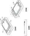
FIG. 1 is an isometric view of one embodiment of a reclosable package assembly with the lid member in an open second position;
FIG. 2 is a top view of the lid member of the embodiment of the reclosable packaging assembly of FIG. 1;
FIG. 3 is a cross-sectional view of the cover member taken along line 3-3 of FIG. 2;
FIG. 4 is an isometric view of the embodiment of the reclosable packaging assembly of FIG. 1 with the lid member in a first position of closure;
FIG. 5 is a cross-sectional view of the top wall of the container taken along line 5-5 of FIG. 4;
FIG. 6 is a cross-sectional view of the cover member taken along line 6-6 of FIG. 2;
FIG. 7 is a top view of the top wall of the container of the embodiment of the reclosable package assembly of FIG. 1;
FIG. 8 is an isometric view of a portion of a lid member of the embodiment of the reclosable packaging assembly of FIG. 1;
FIG. 9 is a cross-sectional view of the cover member taken along line 9-9 of FIG. 2;
FIG. 10 is a partial cross-sectional view of the first fastening feature and the second fastening feature of the embodiment of the reclosable packaging assembly of FIG. 1;
FIG. 11A is a partial isometric view of a first fastening feature of the embodiment of the reclosable packaging assembly of FIG. 1;
FIG. 11B is a partial cross-sectional view of a second fastening feature of the embodiment of the reclosable packaging assembly of FIG. 1;
FIG. 12 is a cross-sectional view of the top wall of the container along line 7-7 of FIG. 5, this top wall including a third sheet secured to the first sheet;
FIG. 13 is a partial isometric view of a first engagement feature of an embodiment of a reclosable package assembly;
14A-14H are various views of a mold for forming the first and second engagement features and hinge portion on the container and lid members;
15A-15H are various views of a mold for forming the first and second engagement features and hinge portion on the container and lid members;
figures 16A to 16I are various views of a mold for forming the first and second engagement features and hinge portion on the container and lid members;
17A-17I are various views of a mold for forming the first and second engagement features and hinge portions on the container and lid members;
fig. 18 is a schematic view of a package having a closure assembly according to an embodiment of the present disclosure;
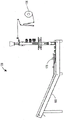
FIG. 19A is a first isometric view of an embodiment of a packaging machine for making an embodiment of a reclosable package assembly 10;
fig. 19B is a second isometric view of the embodiment of the packaging machine illustrated in fig. 19A;
fig. 19C is a third isometric view of the embodiment of the packaging machine illustrated in fig. 19A;
fig. 19D is a fourth isometric view of the embodiment of the packaging machine illustrated in fig. 19A;
fig. 19E is a front view of the embodiment of the packaging machine illustrated in fig. 19A;
fig. 19F is a side view of the embodiment of the packaging machine illustrated in fig. 19A;
FIG. 20A is a top view of the closure assembly of the container of one embodiment of the reclosable package assembly;
FIG. 20B is an isometric view of the closure assembly of the reclosable package assembly of FIG. 20A in a second position;
FIG. 21 is an exemplary forming die for one embodiment of a reclosable package assembly;
FIG. 22 is an exemplary forming die for one embodiment of a reclosable package assembly;
FIG. 23 is an exemplary forming die for one embodiment of a reclosable package assembly;
FIG. 24 is an exemplary forming die for one embodiment of a reclosable package assembly;
FIG. 25 is an exemplary forming die for one embodiment of a reclosable package assembly;
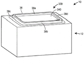
FIG. 26 is a perspective view of a container according to one embodiment of the present disclosure;
FIG. 27 is a top view of the container of FIG. 26 illustrating a closure assembly of the container in accordance with one embodiment of the disclosed packaging assembly;
FIG. 28 is a perspective view of the packaging assembly of FIG. 26, illustrating the lid in an open position;
fig. 29 is a schematic diagram illustrating an embodiment of first and second projections of a closure assembly according to an embodiment of the present disclosure;
30A-30C are schematic views of an opening panel region of a flexible material illustrating sections of the opening panel region, according to embodiments of the present disclosure;
Fig. 30D is a schematic view of an opening panel region illustrating cuts made in various layers used to form a closure assembly, in accordance with an embodiment of the present disclosure;
FIG. 31 is a perspective view of a container having a portion of a transparent or translucent film to provide a window through which a product disposed in the container may be viewed, according to one embodiment of the present disclosure;
fig. 32 is a schematic diagram illustrating an embodiment of first and second tabs and second sheet-to-two sidewall extensions of a closure assembly according to an embodiment of the present disclosure;
FIGS. 33A-33D include various views of one embodiment of a forming tube assembly for a packaging machine for making one embodiment of a reclosable package assembly 10;
FIGS. 34A-34E include various views of an embodiment of a forming tube assembly;
FIG. 35 is a partial side view of an embodiment of a forming tube assembly;
FIG. 36 is a perspective view of an embodiment of a packaging machine for making an embodiment of the reclosable package assembly 10;
FIG. 37 is a perspective view of an embodiment of a packaging machine for making an embodiment of a reclosable package assembly 10;
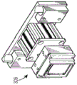
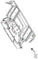
FIG. 38 is a perspective view of one embodiment of a forming station of a packaging machine for making one embodiment of the reclosable package assembly 10;
FIGS. 39A through 45F illustrate various components of the embodiment of the forming station of FIG. 38;
FIG. 46 is a perspective view of one embodiment of a packaging machine for making one embodiment of the reclosable package assembly 10;
FIG. 47 is a first example of a graphical layout for patterning and/or coloring on a film;
FIG. 48 is a second example of a graphical layout for patterning and/or coloring on a film;
FIG. 49 is a plot of secant modulus for various polymer films;
FIG. 50 is a schematic view of a flexible material according to one embodiment of the present disclosure;
FIG. 51 is a schematic view of a flexible material according to one embodiment of the present disclosure;
FIG. 52A is a perspective view of one embodiment of a packaging machine for making one embodiment of the reclosable package assembly 10; and
FIG. 52B is a side view of the embodiment of FIG. 52A;
fig. 53A to 53F are various views of the reject stage;
fig. 54A to 54N are various views of a movable cover member;
FIGS. 55A-55B are various views of the container and movable lid member;
56A-56D are various views of a container and a movable lid member;
FIG. 57 is an exemplary forming die for one embodiment of a reclosable package assembly;
FIG. 58 is an exemplary forming die for one embodiment of a reclosable package assembly;
FIGS. 59A-59E are exemplary forming dies for one embodiment of a reclosable package assembly;
fig. 60A to 60C are packaging assemblies according to an embodiment of the present disclosure;
FIGS. 60D-60H are exemplary forming dies for one embodiment of a reclosable packaging assembly;
FIGS. 61A through 61E are exemplary forming dies for one embodiment of a reclosable packaging assembly;
FIGS. 62A-62E are exemplary forming dies for one embodiment of a reclosable package assembly;
FIGS. 63A-63E are exemplary forming dies for one embodiment of a reclosable packaging assembly;
FIGS. 64A-64E are exemplary forming dies for one embodiment of a reclosable package assembly;
FIGS. 65A-65E are views of an exemplary forming die for one embodiment of a reclosable packaging assembly;
FIG. 65F is a top view of a lid member of a reclosable package assembly according to one embodiment of the present disclosure;
FIG. 66 is a schematic view of a packaging machine for forming reclosable package assemblies in accordance with one embodiment of the present disclosure;
FIGS. 67A-67E are schematic diagrams of a forming die for forming one embodiment of a reclosable package assembly;
68A-68F are cross-sectional images of a cover member according to one embodiment of the present disclosure;
FIG. 69A is a schematic view of a reclosable package assembly according to one embodiment of the present disclosure;
FIG. 69B is a cross-sectional illustration of a closure assembly illustrating a groove on an inner wall of a channel for improved sealing when a lid is in a closed position according to one embodiment of the present disclosure;
FIG. 70 is a schematic view of a forming die used to form one embodiment of a reclosable package assembly;
FIGS. 71A through 71E are schematic views of a forming die for forming one embodiment of a reclosable package assembly;
fig. 72 illustrates a film layout for forming a package according to one embodiment of the present disclosure;
fig. 73A illustrates one embodiment of a second sheet as illustrated in a configuration provided in a package according to one embodiment of the present disclosure;
fig. 73B illustrates an embodiment of a package having a second sheet according to an embodiment of the present disclosure;
figures 74A to 74F are schematic views of a heating plate for heat sealing the sealing flap to one side of the package;
FIGS. 75A through 75K are schematic illustrations of a forming die with an integrated cutting die and external forming station, according to one embodiment of the present disclosure;
fig. 76A to 76E are various views of a schematic of a packaging machine having a racetrack conveyor belt according to one embodiment of the present disclosure;
fig. 76F is a schematic view of the racetrack conveyor illustrated in fig. 76A-76E;
fig. 77 is a diagram illustrating an exemplary two-layer and three-layer film stack construction suitable for use in various embodiments of the present disclosure;
FIG. 78 is a perspective view of one embodiment of a VFFS machine;
fig. 79A through 79F are various views of an embodiment of the VFFS machine of fig. 78;
FIGS. 80A-80B are various views of one embodiment of an edge folding station;
FIG. 81 is a perspective view of one embodiment of a sealed container;
FIGS. 82A-82B are various views of an embodiment of a fin sealing station assembly;
FIGS. 83A-83B are various views of an embodiment of a fin seal station assembly;
FIGS. 84A to 84D are various views of an embodiment of a lapel former;
FIGS. 85A through 85G are various views of one embodiment of an edge folding station;
FIGS. 86A-86G are various views of an embodiment of a flap sealing station assembly;
FIGS. 87A-87G are various views of an embodiment of a flap sealing station assembly;
FIGS. 88A-88G are various views of an embodiment of a fin sealing station assembly;
FIGS. 89A-89G are various views of one embodiment of a flap seal station assembly;
FIG. 90 is a schematic view of a film layout of a container according to one embodiment of the present disclosure;
FIG. 91 is a schematic view of a flexible container showing a resealable flap on the top panel and in an open position according to one embodiment of the present disclosure;
FIG. 92 is a schematic view of a flexible container showing a resealable flap on the front panel and in an open position according to one embodiment of the present disclosure;
FIG. 93 is a schematic view of a contoured package according to one embodiment of the present disclosure;
FIG. 94 is a schematic view of a film layout of the contoured package of FIG. 93;
FIG. 95 is a schematic view of a contoured package according to another embodiment of the present disclosure;
FIG. 96 is a schematic view of a film layout of the contoured package of FIG. 95;
fig. 97 is a schematic diagram of a film layout of a contoured package according to one embodiment of the present disclosure; and
fig. 98 is a schematic illustration of a film layout of a contoured package according to another embodiment of the present disclosure.
Detailed Description
Reclosable package assembly
As illustrated in fig. 1, reclosable package assembly 10 includes a container 12 formed at least in part from a first sheet 14 (also referred to as a first film), and container 12 has a plurality of walls 16 that cooperatively define an interior volume 18. The container 12 has an opening 20 through at least one of the plurality of walls 16. The reclosable package assembly 10 also includes a closure assembly 22 secured to the container 12 adjacent to the opening 20 (or the area defining the opening 20). The closure assembly 22 includes, at least in part, a second sheet 24 (also referred to as a second film) and optionally a portion of the first sheet 14 (see fig. 3). For example, a portion of the first sheet 14 may be detached from the first sheet 14 and remain adhered to the second sheet to form an aperture in the first sheet. In other embodiments, a portion of the first sheet 14 may be detached from the remainder of the first sheet and discarded rather than adhered to the second sheet 24 to form the aperture. The terms container and package are used interchangeably herein.
In one embodiment, the closure assembly 22 includes a lid member 26 and a hinge portion 28. The cover member 26 is pivotable about the hinge portion 28 between a first position 30 (illustrated in fig. 4) in which the cover member 26 releasably engages a first portion 32 of the container 12 about the opening 20 and a second position 34 (illustrated in fig. 1 and 28) in which the cover member 26 pivots about the hinge portion 28 away from the opening 20, thereby allowing a user to access the interior volume 18 through the opening 20. As illustrated in fig. 1 and 5, the first engagement feature 36 may be disposed on the container 12 adjacent to the opening 20. As illustrated in fig. 1, 2, and 3, the second engagement feature 38 may be disposed on the lid member 26 of the closure assembly 22. The first engagement feature 36 engages the second engagement feature 38 when the cover member 26 is in the first position 30 to movably secure the cover member 26 to the container 12. The first engagement feature 36 may be integrally formed with the container 12. As illustrated in fig. 1, 3, and 5, for example, the first engagement feature 36 may be shaped as a ridge 40 and the second engagement feature 38 may be shaped as a channel 42 adapted to receive the ridge 40.
The thus configured lid member 26, first engagement feature 36, and second engagement feature 38 may be formed in the film of the container 12 in a single manufacturing step, thereby eliminating the need to attach a separately manufactured lid assembly secured to the container. Because these features are formed in a single process step, and because a separately manufactured lid assembly is not necessary, one of ordinary skill in the art will recognize that manufacturing time and cost are reduced. Furthermore, those of ordinary skill in the art will recognize that these features allow for reliable resealing of the lid member 26 to the container 12 with a mechanical closure that is not degraded by the presence of surface contaminants in the sealing area.
Turning in more detail to the container 12 of the reclosable package assembly 10, as illustrated in FIG. 1, the container 12 includes a plurality of walls 16 that cooperatively define an interior volume 18. The plurality of walls 16 may cooperate to form any suitable shape or combination of shapes. For example, the plurality of walls 16 may include a top wall 16a, a first side wall 16b, a second side wall 16c, a third side wall 16d, a fourth side wall 16e, and a bottom wall 16 f. The top wall 16a may be planar or substantially planar and may extend in a horizontal direction (i.e., parallel to the X-Y plane of the reference coordinate system provided in fig. 1) or a substantially horizontal direction. The bottom wall 16f may be planar or substantially planar and may extend in a horizontal or substantially horizontal direction, and the bottom wall 16f may be offset vertically (i.e., in a direction parallel to or along the Z-axis of the reference coordinate system provided in fig. 1) from the top wall 16 a. First side wall 16b may extend perpendicularly between top wall 16a and bottom wall 16f, and first side wall 16b may be parallel or substantially parallel to the X-Z plane of the reference coordinate system provided in fig. 1. A first portion of the first side wall 16b may extend perpendicularly beyond the top wall 16a to form a portion of the top ridge wall 44 that extends along and around the perimeter of the top wall 16 a. A second portion of the first side wall 16b may extend perpendicularly beyond the bottom wall 16f to form a portion of the bottom ridge wall 46 that extends along and around the perimeter of the bottom wall 16 f.
Still referring to fig. 1, the second sidewall 16c may extend perpendicularly between the top wall 16a and the bottom wall 16f, and the first sidewall 16b may be offset from the second sidewall 16c along the Y-axis of the reference coordinate system provided in fig. 1. A first portion of the second side wall 16c may extend perpendicularly beyond the top wall 16a to form a portion of the top ridge wall 44. A second portion of the second side wall 16c may extend perpendicularly beyond the bottom wall 16f to form a portion of the bottom ridge wall 46. The third side wall 16d may extend perpendicularly between the top wall 16a and the bottom wall 16f, and the third side wall 16d may be parallel or substantially parallel to the Y-Z plane of the reference coordinate system provided in fig. 1. A first portion of the third side wall 16d may extend perpendicularly beyond the top wall 16a to form a portion of the top ridge wall 44. A second portion of the third side wall 16d may extend perpendicularly beyond the bottom wall 16f to form a portion of the bottom ridge wall 46. First sealing edge 48 may extend perpendicularly from top ridge wall 44 to bottom ridge wall 46. The third side wall 16d may not be directly attached to the top wall 16a, and a portion of the first sheet 14 comprising the top wall 16a may be inserted through a gap between the third side wall 16d and the top wall 16a such that the portion of the first sheet 14 is disposed against a portion of the inner surface of the third side wall 16d (i.e., pleating the portion of the top wall 16a into the gap). Similarly, the third side wall 16d may not be directly attached to the bottom wall 16b, and a portion of the first sheet 14 comprising the bottom wall 16b may be inserted through a gap between the third side wall 16d and the bottom wall 16b such that the portion of the first sheet 14 is disposed against a portion of the inner surface of the third side wall 16d (i.e., pleating a portion of the bottom wall 16b into the gap).
Referring again to fig. 1, a fourth side wall 16e may extend perpendicularly between the top wall 16a and the bottom wall 16f, and the fourth side wall 16e may be parallel or substantially parallel to the Y-Z plane of the reference coordinate system provided in fig. 1. A first portion of the fourth side wall 16e may extend perpendicularly beyond the top wall 16a to form a portion of the top ridge wall 44. A second portion of the fourth side wall 16e may extend perpendicularly beyond the bottom wall 16f to form a portion of the bottom ridge wall 46. Second sealing edge 50 may extend perpendicularly from top ridge wall 44 to bottom ridge wall 46. The fourth side wall 16e may not be directly attached to the top wall 16a, and a portion of the first sheet 14 comprising the top wall 16a may be inserted through a gap between the fourth side wall 16e and the top wall 16a such that the portion of the first sheet 14 is disposed against a portion of the inner surface of the fourth side wall 16e (i.e., pleating the portion of the top wall 16a into the gap). Similarly, the fourth side wall 16e may not be directly attached to the bottom wall 16b, and a portion of the first sheet 14 comprising the bottom wall 16b may be inserted through a gap between the fourth side wall 16e and the bottom wall 16b such that the portion of the first sheet 14 is disposed against a portion of the inner surface of the fourth side wall 16e (i.e., pleating the portion of the bottom wall 16b into the gap).
The walls 16 of the container 12 may cooperate to form any suitable shape or combination of shapes that form a sealed or partially sealed enclosure. In other embodiments contemplated, for example, the plurality of walls 16 may form a substantially elongated tubular shape. The container 12 may comprise any container known in the art, such as a quad-sealed package, a horizontal wrap-around package (such as those manufactured by ilapaak, Hayssen-sandirare, Bosch, or Doboy), a vertical form fill seal "pillow" style bag (such as those manufactured by Hayssen, ilapaak, Bosch, or Triangle), a horizontal form fill seal package comprising a formed base and a lidding material (such as those manufactured by Multivac or Tiromat), a free standing bag (such as those manufactured by KHS-bartel or Laudenberg), and a tray sealing apparatus such as those manufactured by Pack-Line, osod, or moden.
Exemplary quad-sealed packages and methods of folding quad-sealed packages that may be used as containers for the packages of the present disclosure are described in U.S. patent application publication No. 2012/0312868, the disclosure of which is incorporated herein by reference in its entirety. These quad-sealed packages may include corner seals that extend around and surround one or more panels of the package. For example, a package may include a top wall disposed with an opening and an oppositely disposed bottom wall. The corner seals may extend from and surround one or both of the top and bottom walls. In alternative embodiments, corner seals may extend from one or more of the side walls.
As illustrated in fig. 1, one or more ribs 51 may be formed along one or more surfaces of the container 12. For example, the rib 51 may extend along the top wall 16a of the container 12 adjacent to and aligned with the third side wall 16d of the container. In some embodiments, as illustrated in fig. 26, for example, the first rib 251a can extend along the top wall 216a of the container, which is adjacent to and aligned with the third sidewall 216 d; and the second rib 251b may extend along the top wall 216a of the container, adjacent to the fourth side wall 216e and aligned with the fourth side wall 216 e. One or more ribs 51 may be shaped as an elongated protrusion extending upwardly from the top wall 16a of the container 12, and this protrusion may provide rigidity to a desired area of the container 12. Additionally, one or more ribs 51 may extend along all or a portion of one or more of the side walls 16b-d of the container 12 and upwardly from the container wall as described above with respect to the top wall. In various embodiments, one or more ribs 51 may be formed in the wall containing the closure assembly 22 and on one or more walls adjacent to the panel with the closure assembly. One or more ribs 51 may be formed in a thermoforming operation, which operation will be described in more detail below.
The plurality of walls 16 of the container 12 may be formed from a single sheet of material (e.g., the first sheet 14), and such material may be flexible. However, the container 12 may be made from any suitable number of sheets of material. The first sheet 14 may include any suitable number of laminate layers as needed to achieve the desired composition and/or film properties. The first sheet 14 may have a composition and structure suitable for the product to be stored within the container 12. The first sheet 14 may be formed of: such as polypropylene (PP), ethylene vinyl alcohol (EVOH), Polyethylene (PE), Ethylene Vinyl Acetate (EVA) copolymers, foils such as aluminum foil, paper, Polyester (PET), polyamide or nylon (PA), and laminates and composites thereof. In other embodiments, the first sheet 14 may be formed of metallized polypropylene or metallized polyethylene terephthalate (PET), or a combination of these materials. In addition, the first sheet 14 may include or be impregnated with a degradable or biodegradable component that may allow the container to degrade in a relatively short period of time after the useful life of the container 12, such as after the container 12 is placed in a landfill or other disposal facility. As necessary or desired based on the implementation, first sheet 14 may include an outer layer of heat sealable polypropylene or other material suitable for heat sealing such that the seal connecting the film portions may be sealed and/or attached to the outer surface of container 12 to form and shape container 12 when container 12 is manufactured.
As illustrated in fig. 1, the container 12 includes an opening 20 through at least one of the plurality of walls 16. The opening 20 may be disposed through any suitable wall of the plurality of walls 16. For example, as illustrated in fig. 1, the opening 20 may be disposed through the top wall 16a (i.e., access panel or opening panel). The term opening panel as used herein is used to describe any panel in which an opening is formed or defined. The opening 20 may have any suitable shape or combination of shapes to allow a user to access the interior volume 18 through the opening 20. For example, as illustrated in fig. 1 and 7, the opening 20 may have an elongated shape that extends along a horizontal opening axis 52 that is parallel to the X-axis of the reference frame of fig. 1. The opening axis 52 may extend from a first end 53 of the opening 20 to a second end 54 opposite the first end 53, and the opening axis 52 may extend at least partially along or adjacent to a top surface of the first sheet 14 including the top wall 16 a. The opening axis 52 may be equidistant from the first sidewall 16b and the second sidewall 16c when viewed along the Z-axis of the reference frame of fig. 1. The perimeter of the opening 20 may be bounded by an opening edge 55, and the opening edge 55 may include one or more segments. For example, the opening edge 55 may include a first side edge 56a and a second side edge 56b, and each of the first side edge 56a and the second side edge 56b may be parallel to the opening axis 52 and equidistantly offset from the opening axis 52. Each of the first side edge 56a and the second side edge 56b may be disposed at a first distance D1 from the opening axis 52. The opening edge 55 may also include an end edge 58, and the end edge 58 may extend between a first end of the first side edge 56a and a first end of the second side edge 56b at the second end 54 of the opening 20. The curved front edge 60 may extend from the second ends of the first and second side edges 56a, 56b toward the first end 53 of the opening 20. The front edge 60 may be symmetrically formed about the opening axis 60, and the distance between the front edge 60 and the opening axis 24 may increase from the first end 53 of the opening 20 to the second end of the first and second side edges 56a and 56 b. For example, the front edge 60 may have the shape of a portion of a circle, a portion of an ellipse, or a portion of a parabola, square, or rectangle. The leading edge 60 may also have a point or V-shape (not shown) to establish a starting point. The edge surface of the opening edge 55 may be smooth, wavy, scalloped, or have any other suitable texture or shape. The opening 20 may have a symmetrical or asymmetrical shape.
The openings 20 may be formed in a cutting operation. For example, in one embodiment, the cutting operation may include forming cuts of the first and second side edges 56a, 56b and the front edge 60 from the first sheet 14, while all or a portion of the end edge 58 may remain integrally secured to the first sheet 14 to form a portion of the hinge portion 28. In such operation, a lower portion 62 of the first sheet 14 is formed that is disposed inwardly of the first and second side edges 56a, 56b and the front edge 60 (when formed in the cutting operation) and that may be pivotally coupled to the container 12 about the portion of the first sheet 14 at or adjacent the end edge 58. In an alternative embodiment, the opening 20 may be formed in a cutting operation that cuts along the entire opening edge 55. The cutting operation may cut along substantially the entire opening edge 55 and may provide a gap or bridge along the opening edge 55 as desired.
In an alternative embodiment, the opening 20 may be defined in the container 12 (such as on the top wall 16a of the container) by forming or defining a lower portion 62 in a portion of the top wall 16a such that the opening 20 is defined when the lower portion 62 is at least partially removed from the remainder of the top wall 16 a. That is, the lower portion 62 may not be secured to the cover member 26. This may allow the reclosable package assembly 10 to remain sealed, e.g., hermetically sealed, until first used by a user. Such an embodiment may be advantageously utilized to provide a tamper-evident package assembly 10 in which a user would be able to readily determine whether the package 10 has been previously opened by observing whether the lower portion 62 has been at least partially detached from the container 12. Any other known tamper-evident mechanism may be provided on the container 12, as is known in the art. The lower portion 62 may be configured to be fully or partially disengaged from the remainder of the container 12. For example, the lower portion 62 may be configured to be partially detached from the container 12 such that it remains at least partially attached to the container 12. In other embodiments, the lower portion 62 may be completely detached from the access panel 14.
Referring to fig. 3, the lower portion 62 of the first sheet 14 may be at least partially secured to the second sheet 24 of the cover member 26. More specifically, all or a portion of the first surface 90 of the lower portion 62 may be secured to all or a portion of the second surface 92 of the second sheet 24 of the cover member 26. Preferably, the entire first surface 90 of the lower portion 62 may be secured to a portion of the second surface 92 of the cover member 26. The lower portion 62 may be secured to the second sheet 24 of the cover member 26 in any manner known in the art, such as by using an adhesive, heat sealing, ultrasonic sealing, or the like. Suitable adhesives may be, for example, pressure sensitive acrylics, two-part dry adhesives, one-part polyurethanes, and heat activated adhesives. Because lower portion 62 may be formed in a cutting operation that forms opening 20, lower portion 62 may have dimensions that are equal or substantially equal to corresponding dimensions of opening 20. Specifically, as illustrated in fig. 2, 3, 6, and 8, lower portion 62 may have first and second side edges 94a, 94b that correspond in size to first and second side edges 56a, 56b of opening 20 and a front edge 96 that corresponds in size to front edge 60. At the first position 30, the longitudinal axis of the lower portion 62 may be collinear with the opening axis 52, and the lower portion 62 may be formed symmetrically about the longitudinal axis.
Other suitable methods of forming score lines or perforations to define the edges of the opening include laser scoring/cutting, laser perforation or microperforation methods, such as using a die or knife.
As illustrated in fig. 1, the first engagement feature 36 may be disposed on the container 12 adjacent to the opening 20, and the first engagement feature may be on the container 12 or integrally formed with the container 12. The first engagement feature 36 may be adapted to engage a second engagement feature 38 disposed on the lid member 26 of the closure assembly 22 such that the first engagement feature 36 engages the second engagement feature 38 to movably secure the lid member 26 to the container 12 when the lid member 26 is in the first position 30 illustrated in fig. 4. The first engagement feature 36 may be any element or combination of elements that engage a corresponding second engagement feature 38 to allow the cover member to releasably engage the container 12. For example, the first engagement feature 36 may be a ridge 40, which may extend vertically upward from the top wall 16a and may be formed on the top wall 16a or integrally with the top wall 16 a. The spine 40 may extend along a spine axis 64, the spine axis 64 having a generally U-shape (when viewed along the Z-axis of the reference frame of fig. 1) and extending around the opening 20, and the open end of the U-shaped spine axis 64 may be at or adjacent the second end 54 of the opening 20. Spine axis 64 may be offset outwardly from first side edge 56a, second side edge 56b, and front edge 60 by a uniform distance.
As illustrated in fig. 1 and 5, the ridges 40 may be formed in the first sheet 14 and may have any suitable cross-sectional shape or combination of shapes (when viewed along a ridge axis 64). For example, the spine 40 may include a pair of inwardly tapered sides 66a, 66b and a top wall 68. The cross-sectional shape of the spine 40 may be uniform or substantially uniform along the spine axis 64. However, the ends of the ridges 40 that make up the legs of the U-shape adjacent the second end 54 of the opening 20 may taper gradually downward such that the top wall 68 is flush or substantially flush with the top surface of the first sheet 14 (i.e., the top surface of the top wall 16 a). Instead of tapering, the ends of the ridges 40 may be chamfered or may be rounded. Alternatively, the ends of the spine 40 may not be tapered, and the cross-sectional shape of the spine 40 may be uniform or substantially uniform along the entire spine axis 64.
As previously explained, the ridges 40 may be adapted to engage corresponding channels 42 (see fig. 3) formed in the lid member 26 of the closure assembly 22 when the lid member 26 is in the first position 30 illustrated in fig. 4, and the channels 42 will be described in more detail below. Instead of a single ridge 40, the first engagement feature 36 may include two or more ridge segments (not shown) that are discontinuous over the length of the ridge axis. That is, the gap may separate two or more ridge segments, and each of these ridge segments may be adapted to engage a corresponding channel segment or portion of a channel 42 formed in the lid member 26 of the closure assembly 22 when the lid member 26 is in the first position 30.
As illustrated in fig. 1, the reclosable package assembly 10 also includes a closure assembly 22 that is secured to the container 12 adjacent to the opening 20 or adjacent to an area defining the opening (such as when the lower portion 62 acts as a removable seal to cover the opening 20). The closure assembly 22 includes a lid member 26 and a hinge portion 28, and the lid member 26 is pivotable about the hinge portion 28 between a first position 30 and a second position 34. At least a portion of the closure assembly 22 can include the second sheet 24 and a portion of the first sheet 14. More specifically, the cover member 26 may partially include the second sheet 24, and the second sheet may be sized and dimensioned to cover the opening 20 when the cover member 26 is in the first position 30. The second sheet 24 may be any suitable material, such as any of the previously described materials that may comprise the first sheet 14. In particular, the second sheet 24 may be PP, PET or PLA, or any other suitable material. The second sheet 24 may have a uniform thickness, or the thickness may vary. At this first position 30, as illustrated in fig. 2 and 4, the cover member 26 may have an elongated shape extending along a longitudinal cover axis 70 from a first end 72 to a second end 74 adjacent the hinge portion 28. The cover shaft 70 may extend at least partially along or adjacent to the bottom surface of the second sheet 24 (and the top surface of the first sheet 14) such that the cover shaft 70 is collinear (or substantially collinear) with the opening shaft 52 when the cover member 26 is in the first position 30. In an alternative embodiment, the lid member 26 of the closure assembly 22 may include only the second sheet 24, and the lower portion 62 may remain secured to the container 12 to cover the opening 20 and act as a seal as previously described.
As illustrated in fig. 2 and 8, the cover member 26 may include a cover edge 76 that defines an outer edge (or outer perimeter edge) of the cover member 26, and the cover edge 76 may include one or more segments. For example, the lid edge 76 may include a first side edge 78a and a second side edge 78b, and each of the first side edge 78a and the second side edge 78b may be parallel to the lid axis 70 and equidistantly offset from the lid axis 70. Each of the first and second side edges 78a, 78b may be disposed at a second distance D2 from the lid axis 70, and the second distance D2 may be greater than the first distance D1 separating each of the first and second side edges 56a, 56b from the opening axis 52. The first end of the first side edge 78a and the first end of the second side edge 78 may be disposed adjacent the hinge portion 28 at the second end 54 of the opening 20.
The cover edge 76 may also include a curved front edge 80 extending from the second end of the first side edge 78a and the second end of the second side edge 56b toward the first end 53 of the opening 20. The leading edge 80 may be symmetrically formed about the lid axis 60, and the distance between the leading edge 80 and the lid axis 70 may increase from the first end 72 of the lid member 26 to the second ends of the first and second side edges 78a, 78 b. The front edge 80 may have the same or substantially the same general shape as the front edge 60 of the opening 20. That is, the leading edge 80 may have the shape of a portion of a circle, a portion of an ellipse, or a portion of a parabola, square, or rectangle, for example. The leading edge 80 may be offset outwardly from the leading edge 60 of the opening and the offset distance may be uniform. For example, the offset distance may be the difference between the second distance D2 of the cover member 26 and the first difference D1 of the opening 20. The front edge 80 may include a pull tab 117 (illustrated in fig. 20A and 20B), the pull tab 117 protruding from the second engagement feature 38 to assist a user in opening and closing the lid member 26.
As illustrated in fig. 2, 3, 4, and 8, the lid member 26 of the closure assembly 22 includes a second engagement feature 38, the second engagement feature 38 adapted to engage the first engagement feature 36 disposed on the container 12 to movably secure the lid member 26 to the container 12 when the lid member 26 is in the first position 30 illustrated in fig. 4, and the second engagement feature 38 may be on the lid member 26 or integrally formed with the lid member 26. The second engagement feature 38 may be any element or combination of elements that engage the corresponding first engagement feature 36 to allow the cap member to sealingly engage the container 12. For example, the second engagement feature 38 may be a channel 42 adapted to receive a ridge 40 formed on the top wall 16a of the container 12. As illustrated in fig. 3, the channel 42 may extend vertically upward (or substantially vertically upward) from the first surface 82 of the second sheet 24, and as shown in fig. 2, the channel may extend along a channel axis 84. The channel shaft 84 may have a generally U-shape, and the open end of the U-shaped channel shaft 84 may be at or adjacent the second end 74 of the cover member 26. Referring to fig. 54A and 59A-65F, in various embodiments, the channel can be continuous around the entire perimeter of the opening. As described in detail below, in these embodiments, the lid member may be completely removable from the container, or may be hinged to the container, such as at the second end of the lid member. The channel axis 84 may be offset a uniform distance inward from the first side edge 78a, the second side edge 78b, and the front edge 80 of the cover member 26. When the cover member 26 is in the first position 30, but viewed along the Z-axis of the reference frame of fig. 1, the channel axis 84 may overlap or substantially overlap (i.e., have the same shape, size, and relative position) the spine axis 64. The channel 42 may have a uniform or substantially uniform cross-sectional shape along the channel axis 84. Alternatively, the channels 42 may have a non-uniform cross-sectional shape.
Referring to fig. 3, the channels 42 may be formed in the first sheet 14 and may have any suitable cross-sectional shape or combination of shapes (when viewed along the channel axis 84). For example, the channel 42 may include a pair of inwardly tapered surfaces 86a, 86b and a bottom surface 88, and the surfaces 86a, 86b, 88 are adapted to contact or be adjacent to corresponding surfaces of the ridge 40 (i.e., the inwardly tapered sides 66a, 66b and the top wall 68, respectively) when the cover member 26 is in the first position 30. The cross-sectional shape of the channel 42 may be uniform or substantially uniform along the channel axis 84 and may correspond to the cross-sectional shape of the spine 40 along the spine axis 64. The ends of the channels 42 forming the legs of the U-shape adjacent the second end 74 of the cover member 26 may be tapered gradually to receive the corresponding tapered ends of the ridges 40.
Instead of a single channel 42, the second engagement feature 38 may include two or more channel segments (not shown) that are discontinuous over the length of the channel shaft 84. Each of these channel segments may correspond to the previously described ridge segments formed on the top wall 16a of the container 12 such that each of these ridge segments may be adapted to engage a portion of a corresponding channel segment or channel 42 formed in the lid member 26 of the closure assembly 22 when the lid member 26 is in the first position 30.
In an alternative embodiment, the first engagement feature 36 may be a channel 42 that may extend vertically downward from the top wall 16a of the container 12, and the second engagement feature 38 may be a ridge 40 that may extend vertically downward from the lid member 26 of the closure assembly 22. In the first position 30, the ridge 40 may be received into the channel 42 to allow the lid member to sealingly engage the container 12.
Referring to fig. 59A-65F, the cover member may include one or more additional closure features 500, including undercuts in the features, buttons or snaps, or other reciprocal locking features. For example, as shown in fig. 59A-59E, the cover member may include a single closure feature 500 disposed at a first end 502 of the cover 26, and the closure feature disposed at approximately the center may include a downwardly projecting portion formed in the second sheet. When the lid is in the closed position, the downwardly projecting portion formed in the second sheet may interact with, e.g., reside in, a correspondingly shaped and sized pocket formed in the first sheet. Fig. 61 illustrates that the lid can include a closure feature 500 defined by an upwardly projecting portion formed in the first sheet and a receiving recess formed in the second sheet, wherein the receiving recess is arranged such that the upwardly projecting portion resides in the receiving recess when the lid is in the closed position.
The cover member may include any number of closure features. For example, fig. 60A-60C illustrate one implementation having two closure features 500A, 500b disposed at corners of the lid proximate a first end of the lid. The closure feature 500 may be disposed at any suitable location of the lid to help secure the lid 26 in the closed position. For example, the closure feature 500 may be provided in a central region of the lid 26 (as illustrated, for example, in fig. 70), or near an edge of the lid 26 (as illustrated, for example, in fig. 60 and 71). The closure feature 500 can have any suitable shape. For example, fig. 59A-60C illustrate embodiments in which the closure features have a circular shape. Fig. 61A to 61E illustrate one embodiment of a closed feature having an oblong shape. For example, the closure features may have any shape, including circular, oval, square, rectangular, triangular, or any other polygonal shape. Fig. 64A-64E illustrate one embodiment where the closure feature 500 has a teardrop shape that bulges downward from the second sheet 416 toward the opening. The closure feature 500 may have an increasing depth as it approaches the first end of the cover member 26, for example, as illustrated in fig. 64A-64E.
As illustrated in fig. 1, 6, and 8, the cover member 26 of the closure assembly 22 may include a raised portion 98 to provide structural support to the cover member 26. A raised portion 98 may extend from the second end 74 of the cover member 26 toward the first end 72, and a rear edge 100 of the raised portion 98 adjacent the second end 74 may comprise a portion of the hinge portion 28. More specifically, the cover member 26 may pivot about the raised portion rear edge 100 to move from the first position 30 to the second position 34. The rear edge 100 may have the shape of a portion of a circular arc when viewed along the Z-axis, and the shape of the rear edge 100 in combination with the shape of the raised portion 98 cooperate to maintain the cover member 26 in a straight position when in the second position 34. For example, the cover shaft 70 may form an angle between 45 degrees and 125 degrees with the opening shaft 52 when the cover member 26 is in the second position 34. Instead of a circular arc, the trailing edge 100 may include a plurality of circular arc segments or linear segments forming a tortuous mass.
Referring again to fig. 1, 6, and 8, the raised portion 98 may have a parabolic or substantially parabolic shape when viewed along the Z-axis of the reference frame of fig. 1. As illustrated in fig. 6, the raised portions 98 may be symmetrically formed along the lid axis 70, and the distance between the top surface of the first sheet 14 including the raised portions 98 and the lid axis 70 may gradually decrease as the raised portions 98 extend from the second end 74 toward the first end 72 of the lid member 26. For example, as illustrated in fig. 9, the distance between the top surface of the first sheet 14 including the raised portion 98 and the lid axis 70 may gradually decrease as the raised portion 98 extends from the lid axis 70 toward each of the first and second side edges 78a, 78 b. Additionally, the raised portion 98 may have a curved or substantially curved shape when viewed in cross-section along the lid axis 70. In an alternative embodiment, the raised portion 98 may have a generally triangular shape when viewed along the Z-axis of the reference coordinate system of fig. 1, as provided in the illustrations of the thermoforming mold of fig. 17A-17I.
Referring now to fig. 1, the closure assembly 22 can include a support portion 102 extending from the second end 74 of the lid member 26 toward the fourth sidewall 16e of the container 12, and a portion of the support portion 102 adjacent to the second end 74 of the lid member 26 can include a portion of the hinge portion 28. The support portion 102 may be formed from the second sheet 24, and all or a portion of the second sheet 24 of the support portion 102 may be secured to a portion of the first sheet 14 adjacent to the fourth side wall 16e of the container 12 (e.g., the top wall 16a of the container 12). The support portion 102 may structurally secure the cover member 26 to the container 12 and allow the cover member 26 to pivot about the hinge portion 28. A portion of the support portion 102 (either or both of the first and second sheets 14, 24) may extend from the hinge portion 28 through a gap between the fourth side wall 16e and the top wall 16a such that the portion of the first sheet 14 is disposed against a portion of the inner surface of the fourth side wall 16 e. The support portion 102 may be partially defined by a pair of lateral edges 103a, 103b, which pair of lateral edges 103a, 103b may extend parallel or substantially parallel to the first and second side edges 78a, 78b when the cover member 26 is in the first position 30. However, the distance between each of the pair of lateral edges 103a, 103b and the lid axis 70 may be less than the distance between the first and second side edges 78a, 78b and the lid axis 70.
As illustrated in fig. 1, 4, 6, and 7, the reclosable package assembly 10 can also include a first fastening feature 104a and a second fastening feature 104 b. As illustrated in fig. 10, the first fastening feature 104a may be a protrusion formed on the container 12 and the second fastening feature 104b may be a cavity formed on the cover member 26 that is adapted to receive the first fastening feature 104 a. More specifically, as shown in fig. 11A, the first fastening feature 104a may be an elongated protrusion formed along a portion of the spine axis 64, and this protrusion may have a plurality of side walls 106a-d that extend perpendicularly beyond the top wall 68 of the spine 40. The first sidewall 106a and the oppositely disposed second sidewall 106b may be curved to correspond to the contour of the spine axis 64, and the third sidewall 106c and the fourth sidewall 106d may each extend between the first sidewall 106a and the second sidewall 106 b. The third and fourth sidewalls 106c, 106d can have any suitable cross-sectional shape, such as curved, linear, V-shaped, triangular, or partially curved. The top surface 108 may be parallel or substantially parallel to the top wall 68 of the spine 40 and vertically offset from the top wall 68. All or a portion of any or all of the plurality of sidewalls 106a-d may be shaped as an undercut. That is, one or more of the sidewalls 106a-d or a portion of one or more of the sidewalls 106a-d may form an acute angle with the top surface of the top wall 16a of the container 12 (i.e., the first sheet 14). Such an undercut would allow the cover member 26 to be "positively" secured to the container 12. The undercut may also be formed on the first ridge 40 or into the first ridge 40.
As previously explained, the second fastening feature 104b may be a cavity formed on the cover member 26. More specifically, the second fastening feature 104b may be an elongated cavity 109 formed on an underside of a protrusion formed along a portion of the channel axis 84, and the cavity 109 may be adapted to receive the first fastening feature 104 a. As illustrated in fig. 2 and 11B, the cavity 109 may have a plurality of side surfaces 110a-d, each extending vertically upward from a bottom surface 112 of the second sheet 24 of the cover member 26. The first side surface 110a and the oppositely disposed second side surface 110b may be curved or contoured to correspond to the curved shape of the first and second side walls 106a and 106b, respectively, of the first fastening feature 104 a. Similarly, the third and fourth side surfaces 110c, 110d may be shaped to correspond to the shape of the third and fourth sidewalls 106c, 106d of the first fastening feature 104 a.
Referring to fig. 2, 8, and 11B, top surface 114 may be parallel or substantially parallel to bottom surface 88 of channel 42 and vertically offset from bottom surface 88, and the vertical distance between top surface 114 and bottom surface 112 of second sheet 24 of cover member 26 may be greater than the vertical distance between bottom surface 88 of channel 42 and bottom surface 112 of second sheet 24. The first fastening feature 104a may be sized and dimensioned such that the first fastening feature 104a may engage the second fastening feature 104b (e.g., be received into the second fastening feature 104 b) to allow the lid member 26 to sealingly engage the container 12. All or a portion of any or all of the plurality of side surfaces 110a-d may be shaped as an undercut. That is, one or more of the side surfaces 110a-d or a portion of one or more of the side surfaces 110a-d may form an acute angle with the bottom surface 112 of the second sheet 24 of the cover member 26. The undercut of the first fastening feature 104a may engage a corresponding undercut on the second fastening feature 104b to releasably lock or fasten the cover member 26 to the container 12. Instead of an acute angle, a portion of one or more of the side surfaces 110a-d may include a detent that starts at.050 "of the top surface 108, travels downward and inward at a 45 ° angle of about.070", and shifts downward at.050 "and then travels downward and outward at 35 °. These dimensions are for illustrative purposes only, and other dimensions may be suitable. One of ordinary skill in the art will recognize that corresponding similar detents or protrusions may be formed on or in the first fastening feature 104 a.
In alternative embodiments, the first fastening feature 104a may be a cavity formed in the channel 42 that may extend vertically downward from the top wall 16a of the container 12, and the second fastening feature 104b may be a protrusion that may extend downward from the lid member 26 of the closure assembly 22. In the first position 30, the protrusion may be received into the cavity to allow the cover member to sealingly engage the container 12.
One alternative closure assembly 22 is illustrated in fig. 20A and 20B. In this embodiment, the support portion 102 may be at least partially disposed on the top wall 16a of the container 12 or secured to the top wall 16 a. When viewed parallel to the Z-axis of the reference frame of fig. 1, the support portion 102 may be defined by a pair of parallel lateral edges 103a, 103b, and a rear edge 105 extends between the lateral edges 103a, 103b such that the support portion 102 rests on the top wall 16 a. Alternatively, a part of the support portion 102 may be inserted through a gap between the top wall 16a and the fourth side wall 16 e. The hinge portion 28 may include a pair of oppositely disposed cutouts 107a, 107b that may extend inwardly from each of the pair of parallel lateral edges 103a, 103b (and inwardly from the first and second side edges 78a, 78b of the cover member 26 adjacent the second end 74 of the cover member 26). The cutouts 107a, 107b may be symmetrical about the lid axis 70. Each of the cutouts 107a, 107b may include a first segment 111a, 111b orthogonal to the corresponding lateral edge 103a, 103 b. The second segments 113a, 113b may extend obliquely from one end of the first segments 111a, 111b toward the first end 72 of the cover member 26. The third segments 115a, 115b may extend inwardly from respective ends of the second segments 113a, 113b parallel to the first segments 111a, 111 b. The terminal ends of the third segments 115a, 115b may be disposed at a suitable distance from the lid axis 70 such that the lid member 26 may pivot from the first position 30 to the second position 34 about a portion of the closure member extending between the terminal ends of each of the cutouts 107a, 107b (i.e., the terminal ends of each of the third segments 115a, 115 b). Specifically, the cover member 26 can pivot from the first position 30 to the second position 34 about a crease or fold (which can be scored, perforated, or shaped as a feature on the closure member 22) extending between the terminal ends of each of the third segments 115a, 115 b.
When the cover member 26 is pivoted to the second position 34 illustrated in fig. 20B, the first and second cover projections 119a, 119B may snap, deform or move to a position where an edge formed by one or more of the segments 111a, 111B, 113a, 113B, 115a, 115B engages the support portion 102 to support the cover member 26 in the second position 34. Alternatively, the first and second cover projections 119a, 119b may remain fixed relative to the remainder of the cover member 25 when engaging the support portion 102 to support the cover member 26 in the second position 34. As the cover member 26 pivots from the first position 30 to the second position 34, the cover member 26 may deform (e.g., assume a curved shape) to provide longitudinal stiffness to the cover member 26. The second position 34 can be a position intermediate the first position (e.g., the closed position) and a fully open position (third position) in which the cover member 26 or a portion of the cover member can be adjacent to the top portion of the fourth sidewall 16 e. In the second position, the lid axis 70 may form an angle between 30 ° and 120 ° with the top wall 16a of the container 12 (or with the position of the lid axis 70 when the lid member is in the first position 30).
The hinge portion 28 including the cuts 107a, 107b may be used in embodiments where the cover member 26 includes the lower portion 62, and the cuts 107a, 107b may extend through each of the first sheet 14 (lower portion 62) and the second sheet 24. Alternatively, the cuts 107a, 107b may extend only through the second sheet 24 and not through the lower portion 62. The hinge portion 28 including the cutouts 107a, 107b may also be used in embodiments where the cover member 26 is formed from the second sheet 24 only (i.e., when the cover member 26 does not have the lower portion 62). The cuts 107a, 107b may extend through the second sheet 24 (and optionally the lower portion 62), partially through the second sheet 24 (and optionally the lower portion 62), or a combination thereof. The cuts 107a, 107b may be continuous or may include cut segments and gaps between the segments. The cuts 107a, 107b may be perforated or scored (or any combination thereof).
The hinge portion 28 described above, including the cutouts 107a, 107b, may also be suitable for use in packages that do not include a cover member 26. For example, the package may generally include a resealable or reclosable label disposed on the first sheet 14 covering the opening 20. The hinge portion 28 as described above may be formed in the resealable label as described above to allow the resealable label to pivot about the hinge portion 22 and reside at a position intermediate the closed and fully open positions (i.e., the second position).
As illustrated in fig. 18, the closure assembly 22 may include a locking mechanism 126 that includes a locking feature 128 that is received into a receiving feature 130 when the cover member 26 is in the fully open position. The locking feature 128 may be a protrusion extending upwardly from the cover member 26, and this protrusion may have a rectangular, square, circular, or any other suitable cross-sectional shape or combination of cross-sectional shapes. Receiving features 130 may be formed in the support portion 102 (or in the container 12 itself) on opposite sides of the hinge portion 28, and the receiving features 130 may include a pair of receiving protrusions 132 that are separated to form a receiving slot 134 therebetween. Each of the pair of receiving protrusions 132 may have a rectangular, square, circular, or any other suitable cross-sectional shape or combination of cross-sectional shapes. The width of the receiving slot 134 is approximately equal to or slightly less than the corresponding width of the locking feature 128 such that the locking feature 128 (and, therefore, the entire cover member 26) remains in the receiving slot 134 when the cover member 26 is pivoted about the hinge portion 28 such that the cover member 26 is in the fully open position. An undercut may be formed in the pair of receiving protrusions 132 and/or locking feature 128 to positively lock the locking feature 128 within the receiving slot 134. The locking mechanism 126 may be formed in a thermoforming operation using, for example, one of the molds illustrated in fig. 16A-17I.
Features for holding the lid or resealable flap in an open position
In various embodiments, the closure assembly or resealable flap may include features disposed on the lid member that maintain the lid member in the open position (second position), which may facilitate access to the package. Referring to fig. 26, the cover member 226 may include first and second protrusions 219a and 219b that pivot from a first (closed) position to a second (open) position upon opening the cover member 226. While the following description is provided with respect to a lid that includes two tabs, it should be appreciated that the lid may include any suitable number of tabs, including a single tab or more than two tabs. The projections help to maintain the cover member 226 in the second position. The first and second protrusions 219a, 219b may be disposed in the area of the hinge portion 228 of the cover member 226 and positioned such that the axis of the hinge is between the protrusions and the distal end of the cover 226. Referring to fig. 27, first and second protrusions 219a and 219b each have a first end 230a and a second end 230 b. The projections are formed by cutouts in the cover member such that when the cover member 226 is moved from the first position to the second position the first ends 230a of the projections 219a, 219b remain attached to the cover member 226 and the second ends 230b and periphery of the projections 219a, 219b can disengage from a portion of the second sheet 224 and pivot from the first position to the second position. In the first position, the lid projections 219a, 219b may be disposed generally parallel to the top wall 216a of the package. Referring to fig. 28, in the second position, cover tabs 219a, 219b may be positioned generally perpendicular to top wall 216a of package 212, with second end 230b of each cover tab 219a, 219b in contact with top wall 216a, thereby maintaining cover member 226 in the second position. For example, friction between the projections 219a, 219b and the top wall 216a may resist closure of the lid by gravity. The frictional interference between the protrusions 219a, 219b may depend on how far the top wall 216a is deflected by the protrusions 219a, 219b during movement from the first position to the second position. The amount of friction is sufficient to maintain the cover 226 in the second position, but can be overcome without damaging the projections 219a, 219b to return the cover and projections to the first position (the closed position).
First and second protrusions 219a, 219b may have any suitable shape, such as semi-circular, triangular, semi-hexagonal, and "W-shaped". Fig. 29 is a schematic view of the area of the hinge portion 228 of the cover member 226 having differently shaped and sized lugs 219a, 219 b. In various embodiments, first protrusion 219a and second protrusion 219b have the same shape and the same size. In some embodiments, first tab 219a and second tab 219b may have different shapes and/or different sizes.
First and second tabs 219a, 219b have a length between the first and second ends such that upon pivoting of the cover, first and second tabs 219a, 219b move from the first position to the second position, and first and second tabs 219a, 219b may contact top wall 216a at least at their respective second edges 230 b. The length of the protrusions 219a, 219b can be adjusted to adjust the amount of force that the protrusions 219a, 219b exert on the top wall 216a and cause the top wall 216a to deflect. In various embodiments, the first and second tabs 219a, 219b have a length such that the tabs 219a, 219b do not excessively bend or deform during movement from the first and second positions and can maintain sufficient rigidity to maintain the cover member 226 in the second (open) position.
Referring to fig. 30, first and second protrusions 219a and 219b may have any suitable width or diameter. In various embodiments, the width of the tabs 219a, 219b is selected such that the cut in the cover member 226 used to form the tabs 219a, 219b does not overlap the cut in the first sheet and lower portion (if provided) used to form the opening in the package. By arranging the various cuts in such a manner, the package may be provided such that there is no opening in the package that is not covered by the cover member.
The top wall of the container may include one or more features disposed below the first and second lugs to assist in lug movement. These features are formed on the lid, such as by thermoforming, engagement, and/or any other closure feature, for example, as formed. For example, the top wall may include one or more ridges over which the first and second projections may slide and ultimately abut to help maintain the cover member in the open position.
With reference to fig. 59-64, 70, and 71, the cover member may include additional features to help maintain the cover in the open position and/or add additional stiffness to the cover member. For example, the lid may include a rib projecting upwardly from the top wall of the container. The cover may include corner portions 506 having a thickness greater than a central portion disposed between the corner portions. The varying thickness of the ribs 51 and the position of the ribs 51 relative to the channel 42 may be arranged such that a rear region of the channel resides in the central portion when the cover member 26 is in the open position. The cover member 26 may further include cut-out portions adjacent the rear region of the channel that are adapted to reside on raised corners of the ribs when the cover member is in the open position.
Referring to fig. 65A through 65F, in various embodiments, the cover member may be devoid of these additional features, which may beneficially maximize the opening of the package. Fig. 65A-65E illustrate a mold for forming the cap 26, and fig. 65F illustrates a cap formed using the mold of fig. 65A-65E. As illustrated in fig. 65, the hinge 28 about which the cover 26 pivots may be disposed proximate one end (e.g., the second end) of the cover member 26. The first and second engagement features 34, 36 may be channels and corresponding ridges that define the perimeter of the opening. The cover 26 may further include a tab 219 (described above) to help maintain the cover 26 in the open position.
The lid 26 may also include one or more closure features 500 to help retain the lid in the closed position. Any of the closure features as discussed above may be used. Fig. 65 illustrates an embodiment in which a lower cut is positioned in a corner of the lid to assist closure.
Referring to fig. 67A through 67E, one embodiment of a lid channel having a hexagonal shape is illustrated, wherein the corner regions 508 of the lid 26 are substantially flat or have slight curvature. The turning angle may be, for example, an angle of about 30 degrees to about 60 degrees, about 30 degrees to about 45 degrees, about 30 degrees to about 35 degrees. Other suitable values for the angle of rotation include, for example, about 30, 31, 32, 33, 34, 35, 36, 37, 38, 39, 40, 41, 42, 43, 44, 45, 46, 47, 48, 49, 50, 51, 52, 53, 54, 55, 56, 57, 58, 59, and 60 degrees. A locking mechanism 510 provided as an undercut in the corner region may be provided to help hold the lid in the closed position.
In various embodiments, the lid may be provided with pull tabs disposed in corner regions 508 of the lid 26, as opposed to a central portion of the lid 26. It should be understood herein that a lid according to the present disclosure may include one or more pull tabs 117 disposed at any location of lid 26. Without intending to be bound by theory, it is believed that providing the pull tab 117 in the corner region 508 of the lid 26 may facilitate opening the lid 26 by reducing the amount of mechanical closing force of the lid 26 that must be overcome to open the package as compared to the pull tab 117 disposed in the central region of the lid 117. It has been observed that by providing pull tab 117 in corner 508, the mechanical force to open the container can be reduced from about 1000 grams of mechanical force for the center pull tab to 150 grams of mechanical strength. The embodiment of fig. 70 illustrates one embodiment having two pull tabs 117a, 117b disposed at opposite corners 508 of the front of the lid 26. Any suitable number of pull tabs, including zero or a single pull tab, may be provided on a package according to embodiments of the present disclosure.
Referring to fig. 68A-68E, the lid 26 may have a central portion 512 with a curvature that extends (is concave) down to the interior of the package. The recessed center portion 512 may provide packaging and, in particular, the lid 26 with increased resistance to opening due to internal pressure in the container. For example, during shipping, the package may be subjected to different pressure environments, even to significant vacuum pressures. The recessed portion of the lid may make the lid somewhat resistant to these pressure variations that may be experienced during, for example, shipping.
Additionally, referring to fig. 68 and 69A and 69B, by providing a cover with a downwardly recessed portion 512, a portion of the cover may be disposed below the top surface of the opening panel area and may interact with the side wall 512 of the channel below the top surface of the opening panel area. The side walls 514 of the channel may be provided with a groove 516 disposed around all or a portion of the opening, and a corresponding projection on the edge of the lid may reside in the groove 516 when the lid is in the closed position. This may enhance the sealing of the lid and the resistance of the lid to accidental opening when dropped or otherwise during handling, shipping or storage.
Referring again to fig. 27, the hinge portion 228 of the cover 226 is disposed between the first and second protrusions 219a and 219 b. In one embodiment, hinge portion 228 is disposed in-line with a first end of tab 230 a. The hinge portion 228 may be provided by a cut-out in the cover. The cut defining the hinge portion extends between, but does not overlap, the cuts defining the first and second tabs. The cut-out may be of a length such that the cut-out of the hinge portion also does not overlap with the cut-out in the first sheet 214 and the lower portion 262 (if provided) that defines the opening 220 of the package 212.
The first and second tabs 219a, 219b and associated hinge portions 228 described above can be incorporated into embodiments of the package 212 that include a formed cover or an unformed cover, wherein a portion of the second sheet 224 is movably attached to the first sheet 214 to cover the opening 220 of the package 212.
One or more additional features may be disposed on the ridge 40 of the first engagement feature 36 to further secure the cover member 26 to the container 12. For example, as illustrated in fig. 13, one or more oblong protrusions 124 may project outwardly from the outer tapered side 66b of the ridge 40, and each protrusion 124 may be adapted to engage a corresponding surface of the channel 42 of the cover member 26 to secure the cover member 26 to the container 12 at the first position 30. Alternatively or additionally, one or more protrusions 124 or undercuts may be disposed on a surface of the channel 42 of the cover member 26 to engage a corresponding surface or undercut of the ridge 40 to secure the cover member 26 to the container 12 at the first position 30.
To further assist in coupling the lid member 26 to the container 12 at the first position 30, a releasable surface adhesive may be applied to all or a portion of the lid member 26 that contacts (and sealingly engages) the top wall 16a of the container 12 when the lid member 26 is in the first position 30. Alternatively, or in addition to the adhesives described above, a releasable surface adhesive may be applied to all or a portion of the top wall 16a of the container 12 that contacts the cover member 26 when the cover member 26 is in the first position 30. For example, the surface adhesive may be released. The surface adhesive may be any suitable adhesive that provides adhesion between the lid member 26 and the container 12 during a suitable number of openings and closings by the user. For example, a suitable adhesive may be a pressure sensitive acrylic resin.
As illustrated in fig. 12, a stabilizing portion 180, such as the third sheet 116 (or a third membrane), may secure (or be integrally formed with) the first sheet 14 including the container 12 to increase the gauge of the container 12 in the area of the stabilizing portion 180, thereby providing increased rigidity to the container 12 in a desired area. The stabilizing portion 180 may advantageously be provided only at a portion of the top wall 16a of the container 12 without affecting the gauge of other portions of the container 12. This may be advantageous when forming various reclosable package assembly 10 configurations, where sealing of the edges and/or folding of portions of the first sheet 14 may be more difficult if a film with a generally large gauge is used. Referring to fig. 32, in some embodiments, the third sheet may have one or more portions extending outwardly from the body such that the body remains in the area of the top wall after the package is formed, and the one or more outwardly extending portions are disposed on the one or more side walls. Stabilizing portion 180 may be secured to (or integrally formed with) first sheet 14 in any manner known in the art. Specifically, all or a portion of a top surface 118 (i.e., a first side or surface) of the third sheet 116 may be secured to all or a portion of a bottom surface 120 (i.e., a second side or surface) of the first sheet 14 including all or a portion of the top wall 16a, wherein a top surface 122 (i.e., a first side or surface) of the first sheet 14 may be an outer surface of the top wall 16 a. For example, the third sheet 116 may be secured to the bottom surface 120 of the first sheet 14 such that the opening 20 in the first sheet 14 is completely surrounded by the third sheet 116. The third sheet 116 may extend to the opening edge 55, or may be offset outwardly from the opening edge 55. The third sheet 116 may also extend to any one or more of the first, second, third, and fourth sidewalls 16b-16e, or the third sheet 116 may be inwardly offset from any or all of the first, second, third, and fourth sidewalls 16b-16 e. The distance offset inwardly from each of the sidewalls 16b-16e may vary or may be uniform. To secure the third sheet 116 to the first sheet 14, an adhesive may be applied to all or a portion of the top surface of the third sheet 116. Additionally or alternatively, adhesive may be applied to all or a portion of the bottom surface 120 of the first sheet 14. As an alternative to adhesive, the third sheet 116 may be integrally formed with the first sheet 14, heat sealed to the first sheet 14, or ultrasonically welded to the first sheet 14. The thickness of the third sheet 116 may be uniform or may vary, and may have any thickness that provides the top wall 16a of the container 12 with the desired rigidity to allow the lid member 26 to be in proper sealing engagement with the container 12 at the first location 30.
The stabilizing section 180 may also include a coating, such as an ink or adhesive, selectively applied to the bottom surface 120 of the first sheet 14. Stabilizing portion 180 may also include an additional layer of material disposed on bottom surface 120 of first sheet 14. Such material may have a foam structure, for example. In one embodiment, a coating of polymeric material may be applied to at least a portion of the bottom surface 120 of the first sheet 14 and reacted to form a foam structure and thereby form the stabilizing portion 180. In various embodiments, the stabilizing portion 180 may be provided when forming the first sheet 14. For example, the first sheet 14 may be extruded to have an increased gauge portion in an area of the first sheet 14 adapted to be adjacent to the opening 20. For example, the first sheet 14 may be provided with additional stacked layers in the area of the first sheet 14 adapted to be adjacent to the opening 20, compared to the number of layers in other areas of the first sheet 14, thereby increasing the gauge of the first sheet 14 in the area of the opening 20.
One or more ribs 51 (see fig. 18) or any other protrusion or combination of protrusions, including second engagement feature 38, formed on top wall 16a of container 12 or along top wall 16a of container 12 may allow for vertical stacking of reclosable package assemblies 10. More specifically, the vertically projecting feature may engage a portion of a wall projecting downwardly from the bottom wall 16f of the container, and such engagement limits or prevents relative horizontal movement between the stacked assemblies 10.
As illustrated in fig. 55A, 55B, and 56A-56D, the reclosable package assembly 10 can include a closure assembly 339, the closure assembly 339 can include a lid member 340 similar (or identical) to the previously disclosed hinged embodiments of the lid member 26, except that the lid member 340 can be completely removed from the container 12. That is, the cover member 340 is movable between a first position (fig. 55A) in which the cover member 340 releasably engages a first portion of the container 12 surrounding the opening 20 and a second position (fig. 55B) in which the cover member is not in contact with the container 12, thereby allowing a user to access the interior volume through the opening. The opening 20 may have any suitable shape or combination of shapes, such as rectangular, oval, oblong, circular, and/or polygonal shapes.
Referring to fig. 54A-54N, 55A, 55B, and 56A-56D, the cover member 340 may have any suitable shape or combination of shapes, such as square, oval, oblong, and/or polygonal. More specifically, the cover member 340 may be rectangular. The cover member 340 may be bounded by a first lateral edge 341 and a second lateral edge 432 parallel or substantially parallel to the first lateral edge 341. Alternatively, first lateral edge 341 and second lateral edge 432 may each have any suitable orientation. The first end edge 343 may extend between a first end of the first lateral edge 341 and a first end of the second lateral edge 432. The second end edge 344 may extend between a second end of the first lateral edge 341 and a second end of the second lateral edge 432. The first end edge 343 may be parallel or substantially parallel to the second end edge 344, but the first end edge 343 and the second end edge 344 may have any suitable orientation. For example, each of the edges 341-344 may be linear or may be curved, partially curved, contoured, partially contoured, scalloped, and/or partially scalloped.
The lid member 340 of the closure assembly 339 may include a second engagement feature 38, the second engagement feature 38 adapted to engage a first engagement feature 36 disposed on the container 12 to movably secure the lid member 26 to the container 12 when the lid member 339 is in the first position 30 illustrated in fig. 55A, and the second engagement feature 38 may be on the lid member 340 or integrally formed with the lid member 340. The second engagement feature 38 may be any element or combination of elements that engage the corresponding first engagement feature 36 to allow the lid member 340 to sealingly engage the container 12. For example, as previously described, the second engagement feature 38 may be a channel 42 adapted to receive a ridge 40 formed on the top wall 16a of the container 12. As an additional example, the first engagement feature 36 may be a channel 42 that may extend vertically downward from the top wall 16a of the container 12, and the second engagement feature 38 may be a ridge 40 that may extend vertically downward from the lid member 340 of the closure assembly 339. In the first position, the ridge 40 may be received into the channel 42 to allow the lid member 340 to sealingly engage the container 12.
The second engagement feature 38 can include a first portion 38a, a second portion 38b, a third portion 38c, and a fourth portion 38d, and the first portion 38a, the second portion 38b, the third portion 38c, and the fourth portion 38d can be aligned with the first portion 36a, the second portion 36b, the third portion 36c, and the fourth portion 36d, respectively, of the first engagement feature 36 when the cover member 339 is in the first position 30 illustrated in fig. 55A. Each of the first, second, third and fourth portions 38a, 38b, 38c, 38d may be inward (and optionally equidistant) from the first, second, first and second lateral edges 341, 342, 343, 344, respectively. Each of the first and second portions 38a, 38b may be elongated and may have a longitudinal axis parallel to the first lateral edge 341. Alternatively, each of the first and second portions 38a, 38b may be elongated and may have a longitudinal axis that is curved or bowed (or inwardly curved or bowed) relative to the first lateral edge 341. Each of the third and fourth portions 38c, 38d may be elongated and may have a longitudinal axis that is parallel to the first end edge 343. Alternatively, each of the third and fourth portions 38c, 38d may be elongated and may have a longitudinal axis that is curved or bowed (or inwardly curved or bowed) relative to the first end edge 343. Each of the corresponding first, second, third, and fourth portions 36a, 36b, 36c, 36d of the first engagement feature 36 may be similarly formed on the container 12. Each of the first, second, third, and fourth portions 38a, 38b, 38c, 38d of the second engagement feature 38 may form a continuous, single, uninterrupted feature that completely surrounds the opening 20. Alternatively, one or more gaps or interruptions may be disposed in or between first portion 38a, second portion 38b, third portion 38c, and fourth portion 38d of second engagement feature 38.
As illustrated in fig. 54K through 54N, the reclosable package assembly 10 can also include a pour-out feature 345. The pour spout feature 345 may include any feature or combination of features that allow the material stored in the interior volume of the container 12 to be more easily poured or dispensed. For example, the pour spout feature 345 may be a contoured edge 346 that partially defines the opening 20 formed on the container 12 or partially defines an edge of a movable cut through the lid member 340. Additionally, the pour spout feature 345 may include or partially include a vertical projection in contact with the opening 20 or adjacent to the opening 20, and this vertical projection may be an upwardly extending ridge or flange extending from the top wall 16a of the container. The vertical projections may be thermoformed features that may be formed when forming features of the closure assembly 22. Alternatively, the vertical projections can be formed before or after forming the features of the closure assembly 22.
Resealable flexible container
In various embodiments, the package can be provided with a resealable opening opposite the closure assembly. Any of the features described above, including, for example, the tab 219a, 291b hinges, pull tabs, etc., may be used in a package according to embodiments of the present disclosure having a resealable opening.
Referring to fig. 72 and 73, in one embodiment, the package may be provided with only a first sheet 614 and a second sheet 616 disposed on the first sheet 614 such that the second sheet 616 defines at least a portion of the outer surface of the package in at least one panel of the package. The second sheet 616 may be disposed in the opening panel region 620 of the package and may extend across at least three walls, each of which is adjacent to one of the other walls on which the second sheet is disposed. The second sheet 616 may be disposed over all or only a portion of any of the at least three walls. An opening 20 may be defined in the first sheet 614 and a resealable flap 623 may be defined in the second sheet 616 in the opening panel area 620 to cover the opening. The resealable flap 623 is movable between a closed position in which the flap 623 is resealably attached to the first sheet and covers the opening, and an open position in which the flap 623 is positioned away from the opening and the opening is accessible. The opening panel region 620 may be any wall defining a package, including, for example, a top wall (as illustrated in fig. 72), a front or rear wall, or one or both of a top wall and a front or rear wall. In some embodiments, as illustrated in fig. 73B, the opening 20 may extend from the opening panel region 620 to one or more sidewalls or panels 624 of the package. Fig. 73B illustrates one embodiment of the opening panel 20 extending across the opening panel region 620 and to the side panel 624, with the pull tab 617 located on the side panel 624. In this embodiment, the opening 20 is provided in the opening panel region 620 and the side panel 624, and the resealable flap 623 provided by the second sheet 616 is dimensioned to extend over the opening 20 in the opening panel region 620 and the side panel region 624. The second sheet 616 may be scored, cut, or otherwise perforated to provide a resealable flap portion 623 suitable for resealable sealing to the first sheet 614 in the opening panel area 620 to resealably close the package.
The second sheet 616 is attached to the first sheet 614 in the area of the first sheet it contacts. In various embodiments, the second sheet may be attached to the portion of the film defining the opening, and the portion of the first sheet may be separated from the first sheet and remain attached to the second sheet during the first opening of the package. Alternatively, the first sheet may have a removed portion defining an opening, and the second sheet may be positioned over the opening (where the first sheet portion has been removed). The second sheet may be attached to the first sheet using any known adhesive. For example, portions of the second sheet may be permanently attached to the first sheet, with only the portions of the second sheet defining the resealable flaps being resealable to the first sheet. In other embodiments, the second sheet may be completely attached to the first sheet with the resealable adhesive. Any known method of attaching a film sheet may be used.
Referring to fig. 72, the opening panel region 620 can have a first boundary 626a and a second boundary 626b configured to define a first edge and a second edge of the opening panel of the package. Second sheet 618 may overlap one or both of first border 626a and second border 626b and extend along one or more walls of the package beyond the borders and be secured to the first sheet on the opposite side of the borders. For example, the second sheet 614 may extend down substantially the entire length and width of the opposing walls of the package. In an alternative embodiment, a second sheet 616 may be provided to extend partially down one or more walls of the container. A second sheet may also be provided to extend along one or more lateral edges of the package, which may enhance the strength and stiffness of the package. In one embodiment, a second sheet is provided along each of the four boundaries defining the opening panel 620 and along the four lateral edges of the package. Such an arrangement, when combined with a line of weakness of the second sheet (described below), may allow the membrane to substantially self-assemble into a box in a pop-up box type arrangement. The lines of reduced strength may include perforations and/or score lines.
Without intending to be bound by theory, it is believed that one or more lines of reduced strength in second sheet 616 in various regions of the second sheet at the boundary of the panel and wall, corresponding to the edges and corners of the package, reduce the bending strength of the second sheet such that the second sheet will force the first sheet into a folded orientation, wherein the edges and corners (corresponding to the location perforations) preferentially form and remain in the folded orientation under application of minimal folding force. That is, the edges of the opening panel and the lateral edges of the package may be preferentially formed from a flat sheet of material based on the second sheet of material incorporating perforations along these regions. This may advantageously provide a package with well-defined edges and improved crush resistance when a load is applied against one wall and in particular in the area of the opening panel.
Referring to fig. 90, in various embodiments, second sheet 616 may extend across the top panel and into the tuck formed in the sidewall of the package. Fig. 91 illustrates a package defined by the film layout illustrated in fig. 90. Fig. 92 illustrates one embodiment of a package in which an opening and a resealable flap are provided on the front panel. In the embodiment of fig. 91 and 92, the second sheet is illustrated as extending across the entirety of the top, front and rear walls. It will be appreciated that the second sheet may be disposed only on portions of any of the respective walls. For ease of reference, the reference numerals in fig. 91 and 92 generally refer to portions of the second sheet as described below. The package includes opposing sidewalls 668, and each sidewall includes a seal 667 (illustrated, for example, in fig. 93) disposed therealong.
The tuck is formed by a tucked portion of the first sheet material inwardly toward the interior volume of the container such that the tucked portion of the first sheet material is disposed beneath the seal. The second sheet may include tuck portions 650 that extend into the tuck. As shown in fig. 90, the tuck portion 650 may extend from an adjoining portion of the second sheet that extends across the adjacent wall. In the embodiment shown in fig. 90, the tuck portion extends from the top wall portion of the second sheet, and the top wall portion includes a resealable flap 623 defined therein. However, it is contemplated that the opening 620 and corresponding resealable flap may be disposed in a different wall of the package, such as a front wall or a rear wall, or may be disposed along multiple walls of the package. The tuck portion 650 extends from the top wall portion 652, wherein the boundary between the tuck portion and the top wall portion is the edge between the side wall of the container and the top wall of the container. The second sheet includes one or more lines of reduced strength at or adjacent to the boundaries between the tucked portion and the top wall portion of the second sheet. Fig. 90 illustrates a single line of reduced intensity 653 at each of the boundaries between the top wall portion 652 and the tuck portion 650.
Fig. 72 similarly illustrates an embodiment in which the container includes at least one tuck and the second sheet includes at least one tucked portion 650 adjacent to a boundary of the opening panel region and/or a boundary 638 of the at least one wall region. The tuck fold region 636 is configured to tuck inwardly to define an edge of a wall or panel of the package. The flexible film may include a portion of the second sheet (e.g., detached from other portions of the second sheet) 634 secured to the first sheet in the tuck fold region 636. As described above, the pleated portion 650 of the second sheet 616 may include lines of reduced strength 630s, 630b in the area of the borders 626a, 626b to help fold the flexible film into a crease fold. The pleated portion 650 of the second sheet 616 may provide improved stiffness to the edges of the package at the tuck fold, which in turn may provide improved stiffness to the panels or walls of the package adjacent to the tuck fold. In some embodiments, the second sheet 616 may be provided as a single continuous sheet extending across the opening panel region and the tuck fold region. For example, the flexible material may be folded into a package such that a crease fold area is provided at the border of the opening panel area. For example, the lines of reduced strength 630a, 630b adjacent to the tuck portion may include perforations and/or score lines. A score line, as used herein, refers to one or more continuous or discontinuous lines (linear or non-linear) that penetrate through the thickness of a given portion, expressed herein as a percentage of the penetration thickness. In the tuck region, the perforations may comprise about 50% to about 100% cut openings or score lines about 50% to 100% through the thickness of the second sheet to facilitate folding of the tuck portion and provide a well-defined edge. As used herein, "percent cut" refers to the percentage of the perforation line that is a cut. The perforations comprise cuts and bridges between adjacent cuts, for example, a cut opening percentage of 50% refers to a perforation having cuts and bridges of equal length, such that 50% of the perforation length is a cut and 50% of the perforation length is a bridge. For example, an 80% cut refers to a perforation having a cut that is longer in length than the bridge, such that 80% of the total perforation length is the cut and 20% of the total perforation length is the bridge. Other suitable perforation cut or score penetration percentages adjacent to the lines of reduced strength 630a, 630b of the tuck include about 50% to about 99%, about 60% to about 95%, about 55% to about 80%, about 70% to about 99%, about 75% to about 90%. The cut opening percentage may be, for example, about 50%, 52%, 54%, 56%, 58%, 60%, 62%, 64%, 68%, 70%, 72%, 74%, 76%, 78%, 80%, 82%, 84%, 86%, 88%, 90%, 91%, 92%, 93%, 94%, 95%, 96%, 97%, 98%, 99%, and 100%. The percentage of perforation or reduction in thickness of the line of weakness having perforations and/or score lines may depend on the thickness of the second sheet material. For second sheet 616 having a high caliper (e.g., greater than 10 mils), a high degree of strength reduction at the lines of reduced strength may be required to allow the first and second sheets to preferentially fold into tucks.
As mentioned above, the lines of reduced strength assist in folding the first and second sheets during the pleating operation and advantageously provide a well-defined edge to the top wall at the pleating portion. Without including lines of weakness, it may be difficult, if not impossible, to form darts, depending on the total thickness of the first and second sheets. Furthermore, while such folding can be achieved using relatively thin materials, there are often defects, such as dents, in the folded area because the flexible material resists folding. It has been advantageously determined that the inclusion of lines of reduced strength in the second sheet at the boundary between the tuck portion and the top wall portion induces the first sheet to preferentially form edges along the lines of reduced strength to form well-defined edges. As described in detail below, it has been unexpectedly found that selective placement of lines of reduced strength at various boundaries of the package, including boundaries adjacent to tuck portions as described above, can allow the first sheet to be preferentially folded into a desired package configuration, including for forming contoured packages without requiring modification of the package forming apparatus. This is advantageous because it avoids the need to cost-effectively modify the package forming apparatus (such as the sealing bars) and reduces the time associated with adjusting the package forming apparatus for each configuration of flexible package.
Referring to fig. 72, in any of the embodiments where the second sheet 616 overlaps the boundary or edge of the container, the second sheet 616 may further include lines of reduced strength 630a, 630b or perforations in the portion of the second sheet 616 that overlaps the boundary or edge. The reduced- intensity lines 630a, 630b may be defined by one or more reduced-intensity paths or lines, e.g., two reduced-intensity paths disposed on opposite sides of a boundary or edge. As described above, the extension of the second sheet material that overlaps one or more borders and even extends beyond the borders may beneficially reinforce the corners or edges of the package when formed. The lines of reduced strength facilitate bending of the secured first and second sheets in the region of the edges and may help define sharp or curved edges of the package having improved stiffness. This may also help define the shape of the package, and in some embodiments may help the film to preferentially form into a prescribed package assembly shape during processing.
As illustrated in fig. 72 and 73, an extension of the second sheet overlapping the boundary of the area may be provided in any of the areas of the film including the open panel area and the one or more wall areas. Fig. 72 and 73 illustrate one embodiment of a second sheet secured to a first sheet in an opening panel region and two adjacent wall regions. In this embodiment, the second sheet overlaps and extends beyond the borders 626a, 626b, 628a, 628b of the opening panel area and the wall area. In the embodiment illustrated in fig. 72 and 73, the second sheet further extends around the rim of the container, partially into the side wall of the package. The second sheet is configured to not extend into and interfere with the leading and trailing seals.
The second sheet may overlap along substantially the entire length of the border and/or edge. Alternatively, the sheet may overlap only a portion of the border/edge in one or more regions. In addition, the second sheet may overlap the opposing boundaries 626a and 626b of the region and 628a and 628 b. However, the second sheet may overlap only one boundary, if desired.
Referring to fig. 90, as mentioned above, the second sheet may also include lines of reduced strength at or adjacent to other boundaries between portions of the second sheet corresponding to edges of the containers. For example, fig. 90 illustrates one embodiment in which the second sheet includes first and second panel portions 654 and 656 extending across at least a portion of the front and back walls of the container. A first face portion 654 and a second face portion 656 extend from the top wall portion 652. The respective boundaries between the first and second face portions 654, 656 and the top wall portion 652 may also include one or more lines of reduced strength 658 in the second sheet at or adjacent the boundaries. The weakened strength lines 658 may help provide a well-defined side edge at the top wall and similar other walls of the package. However, the weakened strength line 658 reduces the stiffness of the second sheet in the marginal region of the border when, for example, the package is grasped by a user at the top wall or around the point where the weakened strength line is provided, which may reduce the overall stiffness of the package. The reduction in stiffness is a problem with flexible packages, as such packages may be prone to cracking or sagging, if not sufficiently rigid, during handling or grasping by the user, which may render the package difficult to use. It has been advantageously determined that the reduced intensity line 658 may be provided in a second label at a side edge or other side edge of the top wall that is grasped by the user by controlling the degree of intensity reduction of the reduced intensity line. For example, in the grip region, the weakened strength line 658 illustrated in fig. 90 may comprise perforations having cut openings of about 1% to about 50% or score lines that penetrate about 1% to 50% of the thickness of the second sheet to facilitate folding of the tuck portion and provide a well-defined edge, for example. Other suitable cut opening percentages and/or penetration percentages include about 5% to about 50%, about 10% to about 45%, about 15% to about 40%, about 20% to about 30%, about 20% to about 50%, and about 10% to about 50%. The cut opening percentage and/or may be, for example, about 1%, 2%, 3%, 4%, 5%, 6%, 7%, 9%, 10%, 12%, 14%, 16%, 18%, 20%, 22%, 24%, 26%, 28%, 30%, 32%, 34%, 36%, 38%, 40%, 42%, 44%, 46%, 48%, and 50%. The cut opening percentage and/or the penetration percentage will vary depending on the thickness of the second sheet. For example, if the second sheet is thick, e.g., having a thickness greater than 10 mils, a high percentage of cut openings or score lines may be used to facilitate folding of the relatively thick sheet, which by virtue of its thickness will maintain sufficient stiffness to resist sagging or cracking during gripping of the package. A thinner second sheet, such as a second sheet having a thickness of less than about 10 mils, may require a low percentage of cut openings or score lines to maintain adequate strength of the package in the gripping region.
According to embodiments of the present disclosure, the cut or score penetration percentage of the first line of reduced intensity 653 disposed at the boundary between the tuck portion 650 and the adjacent wall portion (e.g., the top wall portion 650) may be greater than the cut or score penetration percentage of the second line of reduced intensity disposed in the grip region, e.g., the line of reduced intensity 658 disposed between the top wall portion 650 and the front and rear wall portions 654 and 656. By selectively perforating or scoring as described above, a package may be provided in which the first sheet defining the walls of the package is preferentially folded into a package configuration while maintaining sufficient strength in various regions of the package that may be grasped by a user during operation.
Still referring to fig. 90, the second sheet can include sidewall portions 660 extending to respective sidewalls of the container and extending from the first and second face portions 654 and 656 of the second sheet. Sidewall portion 660 may be dimensioned so as not to extend into the area of the first sheet, which is sealed to form a seal disposed in the sidewall. In some embodiments, one or more sidewall portions 660 can extend up to, but not into, the seal. In these embodiments, the seal can be folded over and sealed to one sidewall portion. Alternatively, one or more of the side wall portions may terminate at an edge spaced away from the seal such that the seal can be sealed to a portion of the first sheet defining the side wall. In other embodiments, one or both seals may remain extending outwardly from the sidewall. In these embodiments, one or both seals may include an aperture, for example, defined in a portion of the seal, such that the seal may act as a handle and be grasped by a user through this aperture.
The second sheet may be configured such that the end points of the sidewall portions 662 and the pleated portions 664 are on the same line. This configuration of the second sheet may assist in applying the second sheet to the first sheet and ensure that registration of the second sheet and the first sheet is maintained during the package folding process.
The second sheet may comprise one or more lines of reduced intensity 666 disposed at or adjacent to a boundary between a side wall portion and an adjacent face portion, the boundary corresponding to a container edge between the front and/or rear wall and a side wall. The lines of reduced strength may include perforations having any suitable percentage of cut openings and/or score lines having any suitable percentage of penetration. For example, if one or more lines of reduced strength are provided in the gripping area of the container, it may be advantageous to have a lower percentage of cut openings or penetration percentages as described above.
In one embodiment, the lines of reduced strength 666 at or adjacent to the boundary between the sidewall portion and the face portion include perforations having a percent cut opening and/or score lines having a percent penetration equal to those of the lines of reduced strength 658 between the top wall portion and the face portion. In another embodiment, the lines of reduced intensity 666 at or adjacent the boundary between the sidewall portion and the face portion include perforations having a percent cut opening and/or score lines having a percent penetration equal to those of the lines of reduced intensity 653 at or adjacent the boundary of the shirred portion. In another embodiment, the lines of reduced intensity 666 at or adjacent to the boundary between the sidewall portion and the face portion include perforations having a percent cut opening and/or score lines having a percent penetration, such percent being greater than those of the lines of reduced intensity 658 between the top wall portion and the face portion, but less than those of the lines of reduced intensity 653 at or adjacent to the boundary of the tuck portion.
As with the lines of reduced strength described above, the percentage of cuts and/or penetrations may vary depending on the thickness of the material.
It has been advantageously found that by selectively perforating or scoring the second sheet in a controlled manner, a package can be provided in which the first sheet defining the plurality of walls of the package can be induced by the second sheet and controlled perforation to preferentially fold into a package configuration. Other controlled perforations or scoring in various regions of the second sheet as described above may allow such preferential folding while maintaining the stiffness of the container and even improving the stiffness of the container for improved durability, stability, and usability.
As discussed above, it has been surprisingly found that controlled application of a line of non-linear reduced intensity in selected areas of the second sheet can contour the shape of the package without the need for specialized package forming equipment to impart the contoured shape.
FIG. 93 illustrates one embodiment of a contoured package. Fig. 94 illustrates film layers of first and second sheets of a contoured package corresponding to fig. 93. As illustrated in fig. 93 and 94, the weakened strength line formed in the second sheet between the boundary between the side wall portion and the face portion is curved. The curvature of the lines of reduced strength 666 in these areas will induce the first sheet to preferentially form package edges having substantially similar curvature. The curvature of the sidewall 668 can also be controlled using a second sheet. For example, as illustrated in fig. 93, the side walls 667 curve inward. Such curvature may be achieved, for example, by forming sidewall portions 660 of the second sheet to have terminal edges 670 with a curvature corresponding to the curvature of reduced intensity lines 666. In the embodiment of fig. 93 and 94, the second sheet is provided with two opposing side portions 660 extending from adjacent ends of the first face portion 654 (disposed in the front panel). Each side portion 660 terminates at a curved edge 670. The curvature of the curved edge 670 may be similar or identical to the curvature of the reduced intensity line 666, for example. The second face portion 656 disposed on the back wall includes an opposing terminal edge 672 having the same curvature as the reduced intensity line 666 and corresponding to the location of the reduced intensity line 666. Alternatively, the second face portion 656 may include side portions extending therefrom, as with the first face portion, and the weakened strength line having curvature may be provided at the boundary between the second face portion and the side portions in the second sheet, as with the first face portion. The embodiment of fig. 93 and 94 also does not include a tuck portion. However, these portions may optionally be included in this or any of the described embodiments.
Fig. 94 also illustrates an embodiment in which the bottom panel 674 includes an optional reinforcing sheet 676. The reinforcing sheet 676 may be similar to the second sheet and may optionally be attached or detached from the second sheet (as shown in the figures). The reinforcing sheet may be disposed outside of the first sheet or inside of the first sheet. The reinforcing sheet may optionally be sized to reside only in the bottom wall region. Additionally, as described above, a third sheet may be provided inside or outside the first sheet to further provide reinforcement. The third sheet, when provided in an area corresponding to the second sheet, may be similarly perforated or scored for preferential folding of the first sheet.
Fig. 95 and 96 (package and film layout, respectively) illustrate another embodiment of a contoured package. In the embodiment of fig. 95 and 96, the lines of reduced intensity 666, 678 are provided as mirror images about the boundary between the sidewall portion and the face portion, with one line of reduced intensity extending into the face portion and one line of reduced intensity extending into the sidewall portion. As illustrated in fig. 95, the mirror-image weakened strength lines provide a contoured package having a different sidewall shape than illustrated in fig. 93, thereby illustrating the ability of the controlled and selective perforation of the cross-sectional sheet to control the contour of the package. In the embodiment of fig. 95, the sidewall includes two angled portions and a flat portion that is higher than the angled portions, a flap portion with a seal.
Fig. 97 and 98 illustrate other configurations of film layouts for achieving preferential folding of the first sheet into a contoured package configuration.
Other configurations and contours are contemplated and may be achieved by modifying the curvature of the line of reduced strength at the boundary between the sidewall portion and the face portion, the terminal edge of the sidewall portion, and/or the shape of the secondary line of reduced strength included in the sidewall portion. Additionally, one or more regions described as having lines of reduced strength may also be mechanically creased before the first sheet is folded into the packaging configuration.
The features described above, including the cut or penetration percentages of the various lines of reduced strength that may be included in the second sheet, are equally applicable to contoured packages.
Any of the above-described package configurations may include a pull tab 617. The pull tab may extend up to or beyond the adjacent edge of the container for easy gripping. In some embodiments, it may be advantageous to space the pull tab a distance away from the edge of the container, for example, at least about 0.03 inches to about 0.1 inches, about 0.05 inches to about 0.8 inches, about 0.4 to about 0.6, and about 0.02 to about 0.9 inches from the edge of the container. Other spacings include, for example, about 0.03, 0.04, 0.05, 0.06, 0.07, 0.08, 0.09, and 0.1 inches. Such spacing may be advantageous if the pull tab extends adjacent to a line of reduced strength in the second sheet. Such spacing may help maintain strength at the edges having lines of reduced strength. However, it is also contemplated that the tab extends up to or beyond the line of weakness.
In any of the preceding embodiments, the second sheet may include an aperture or otherwise be sized such that the second sheet does not extend past one or more corners of the package. For example, fig. 90 illustrates a film layout in which corner reliefs 678 are provided at each of the four corners of the top panel. The corner relief 678 may be provided at any number of corners of the package. The corner relief 678 is arranged such that the second sheet 616 is disposed around and does not cover one or more corners. Although the corners may be formed with the second sheet 616 disposed in the corner regions, the corners may be sharp and uncomfortable for the user to grasp the container.
In one embodiment, the opening is disposed on the front or rear wall and is arranged such that the tab extending from the resealable flap extends towards the bottom panel of the package. The bottom panel may optionally include a corner seal 677, for example, as illustrated in fig. 95. In these embodiments, the pull tab extending toward the corner seal 676 may allow a user to grasp the corner seal 676 and the pull tab 617 when opening the package to provide a better package grip when opening the package.
Flexible material for forming flexible containers
The flexible material 400 used to form the flexible package 400 includes an opening panel region 420 configured to define a panel of the package (also referred to herein as an opening panel) having an opening for accessing an interior volume of the package. For ease of reference, fig. 30A-C and 50-51 illustrate a shaped feature 422 in the opening panel region 420 corresponding to the closure assembly. It should be appreciated that the forming features need not be included in the flexible material 400 and may be formed during the formation of the package, as described herein. The flexible material 400 may further include one or more wall regions 424 configured to define one or more walls, such as one or more side walls and/or a bottom wall, of the flexible package.
The flexible material may be provided as a web of material capable of forming a plurality of packages, which may be rolled into a roll of flexible material. The flexible material may comprise a plurality of open panel regions and optionally a plurality of wall regions discretely spaced along a longitudinal direction of the flexible material, wherein the plurality of open panel regions and the plurality of wall regions comprise the first sheet. That is, the first sheet may be a universal sheet material extending between each of a plurality of regions configured to be folded or formed into a plurality of packages. The flexible material may further comprise a plurality of second and/or third sheets in the opening panel region and the wall region as described below.
The flexible material includes a first sheet 414 that is configured as disclosed above to form an opening panel and provide an opening and/or may be configured to form more walls of the first sheet 414. The opening panel region 420 and the one or more wall regions 424 comprise the first sheet 414. Flexible material 400 may further include a second sheet 416 secured to first sheet 414 in opening panel area 420. In various embodiments, the second sheet, or at least a portion thereof, is thermoformable.
The term "secured" as used herein refers to one layer or sheet being joined to another layer or sheet and may include intermediate layers or adhesives. The layers or sheets may be joined using any known method, including adhesives, heat sealing, ultrasonic sealing, welding, crimping, and combinations thereof. It is understood herein that a sheet or layer may be secured, in whole or in part, to another sheet or layer, unless otherwise specified. The layers or sheets may be permanently fastened or releasably fastened. The term "permanently secured" as used herein refers to a connection between two adjacent layers or sheets that requires at least partial destruction of one or both of the layers or sheets to separate the layers or sheets at the connection. The term "releasably secured" as used herein refers to a connection between two adjacent layers or sheets such that the layers or sheets can be substantially separated without destruction. In some embodiments, the two sheets may be refastenable, meaning that the sheet layers may be separated and then refastened without the application of additional adhesive or seals.
The flexible material may further include a third sheet 418 secured to the first sheet 414 at least in the opening panel area 420. In one embodiment, the third sheet 418 is secured to the first sheet 414 and the second sheet 416 is secured to the third sheet 418. In another embodiment, the first sheet 414 is disposed between the second sheet 416 and the third sheet 418. As described in detail below, additionally or alternatively, third sheet 418 may be secured to first sheet 414 in one or more wall regions 424 of flexible sheet 400. The third sheet 418 may partially or completely overlap the first sheet in the opening panel region 420 and/or one or more wall regions. For example, fig. 50 illustrates one embodiment where the third sheet 418 completely overlaps the opening panel region 420 and the first sheet in two adjacent wall regions 424a, 424 b. Fig. 51 illustrates one embodiment in which the third sheet 418 only partially overlaps the first sheet 414 in two adjacent wall regions 424a, 424 b.
Referring to fig. 30B illustrating an opening panel area of flexible material, the flexible material may include a line or path of reduced strength 440 in the first sheet 414 of the opening panel area 420 that is configured to define an opening of the package. In embodiments where the flexible material 400 further includes a third sheet 418, lines or paths of reduced strength may be provided in the third sheet to define openings through the first sheet 414 and the third sheet 418. As used herein, the terms "line of reduced strength" and "path of reduced strength" are used interchangeably and may be straight, curved, or have any suitable shape. The lines or paths of reduced strength may be formed in the flexible material or sheet using any known method, including, for example, laser scoring, mechanical scoring, or similar processes for forming perforations. The perforations may be pierced through the sheet of material or provided without piercing the sheet of material, if desired.
The flexible material may further include a weakened strength line or path 442 or continuous cut defined in the second sheet 416 in the opening panel area 420 that is configured to define a hinge 442 about which the lid 26 of the closure assembly 22 of the package may pivot. Additional cuts or reduced strength lines or paths 444a, 444b may be provided in the second sheet 416, as needed, to define the first tab 219a and the second tab 219b of the closure assembly as described in detail below. The cuts or paths or lines of reduced strength of the hinge (442) and the tabs 219a, 219b may be provided in the second sheet so that they do not overlap each other or the paths or lines of reduced strength 440 that define the package opening. This may help ensure that the package remains hermetically sealed until first use.
In various embodiments, as illustrated in fig. 50 and 51, the third sheet 418 can be a single sheet that extends across one or more regions of the flexible material, such as the open panel region 420 and the one or more wall regions 424. In other embodiments, the third sheet 418 may be provided as a separate sheet that overlaps the first sheet 414 in one or more regions of the flexible material. The third sheet may be between the boundaries 426a, 426b, 428a, 428b of the regions as illustrated in fig. 50, 51. Alternatively, the third sheet 418 may extend only partially in one face of the region and/or may be provided as a separate sheet that overlaps but is not contiguous with the border. Fig. 50 illustrates a third sheet portion 434 that extends only partially in the face of the region. As described in detail below, in some embodiments, the third sheet portion 434 may be selectively placed at a boundary in a crease fold region of the flexible material. In these embodiments, the third sheet portion 434 is also referred to herein as the fourth sheet 434. It will be understood herein that in these embodiments, the fourth sheet may be the same or different material as the third sheet.
Referring to fig. 50 and 51, in some embodiments, the flexible material may include a first sheet 414, a second sheet 416, and a third sheet 418 in an opening panel region 420. The opening panel region 420 can have a first boundary 426a and a second boundary 426b configured to define a first edge and a second edge of an opening panel of the package. Third sheet 418 may overlap one or both of first border 426a and second border 426b, and optionally extend beyond the borders and be secured to first sheet 414 on the opposite side of the borders. The third sheet 418 may further include lines of reduced strength 430a, 430b in portions of the third sheet 418 that overlap the boundaries 426a, 426 b. As shown in fig. 50, the reduced intensity lines 430a, 430b may be defined by one or more reduced intensity paths or lines, such as two reduced intensity paths disposed on opposite sides of a boundary. The extension of the third sheet 418 that overlaps one or more of the borders and even extends beyond the borders may beneficially reinforce the corners or edges of the package when formed. The lines of reduced strength facilitate bending of the secured first sheet 414 and second sheet 416 in the area of corners or edges and may help define sharp or curved edges of the package with improved stiffness. As described in detail below, this may also help define the shape of the package, and in some embodiments may help the film to preferentially form into a prescribed package assembly shape during processing. As illustrated in fig. 50, an extension of the third sheet 418 that overlaps the boundary of the area may be provided in any of the areas of the film that include the open panel area and the one or more wall areas. Fig. 50 illustrates one embodiment of a third sheet 418 secured to the first sheet 414 in the opening panel region 420 and two adjacent wall regions 424a, 424 b. In this embodiment, the third sheet overlaps and extends beyond the borders 426a, 426b, 428a, 428b of the opening panel area and the wall area. In the embodiment of fig. 50, the third sheets 418 overlap along substantially the entire length of the border. As illustrated in fig. 51, the third sheet 418 may overlap only a portion of the boundary in one or more regions. In addition, a third sheet may overlap the opposing boundaries 426a and 426b and 428a and 428b of the region. However, the third sheet may overlap only one boundary, if desired.
In some embodiments, for example, for a flexible material of a quad sealed package as described in U.S. patent application publication No. 2012/0312868, the flexible film may include at least one pleated region 436 (as illustrated in fig. 50) adjacent to a boundary of the opening panel region and/or a boundary 438 of the at least one wall region 424 c. The tuck fold region is configured to tuck inwardly to define an edge of a wall or panel of the package. The flexible film may include a fourth sheet 434 secured to the first sheet in a tuck fold region 436. As described above with respect to the third sheet, the fourth sheet may include lines of reduced strength 439 in the area of the border 438 to aid in folding the flexible film into tuck folds. The fourth sheet 434 may provide improved stiffness to the edges of the package at the tuck fold, which in turn may provide improved stiffness to the panels or walls of the package adjacent to the tuck fold. In some embodiments, as mentioned above, the third sheet 418 may function as the fourth sheet 434 and be disposed in the tuck fold region. For example, the flexible material may be folded into a package such that a crease fold area is provided at the border of the opening panel area. As described with respect to the fourth sheet 434, extending the third sheet 418 beyond the boundary as illustrated in fig. 50 may cause the third sheet 41 to extend into and support the tuck fold.
The film may include any suitable printing and/or graphics. For example, all or part of the film may be colored. Referring to fig. 31, in one embodiment, the film may be colored such that a portion of the film remains transparent or translucent to provide a window for viewing the product contained therein. The graphic layout for patterning and/or coloring on the film may be adapted based on the package configuration and the graphics to be displayed on the package. In embodiments where the closure assembly is formed as a lid, the graphical layout illustrated in fig. 47 may be used when performing the lid forming process on the side of the forming tube. In other embodiments where the closure assembly is formed into a lid, the graphical layout illustrated in fig. 48 may be used when performing the lid forming process on the front of the forming tube. The cap forming process may be performed on either side of the forming tube. For example, in one embodiment, multiple sides of a forming tube may be used in a lid forming process to provide alternative forming of the lid on a forming die to increase the per package rate of the forming process.
First sheet
The first sheet 414 may have any suitable thickness, and this thickness may be a uniform thickness or may vary. In various embodiments, the first sheet 414 has a nominal thickness of about 1 mil to about 10 mils, about 3 mils to about 9 mils, about 4 mils to about 8 mils, about 5 mils to about 7 mils, about 2 mils to about 6 mils. Other suitable nominal thicknesses include, for example, about 1, 2, 3, 4, 5, 5.1, 5.2, 5.3, 5.4, 5.5, 5.6, 5.7, 5.8, 5.9, 6, 7, 8, 9, and 10 mils. The term "nominal thickness" as used herein refers to the thickness of a film or sheet material that does not include a layer of ink or adhesive.
Exemplary materials suitable for use as the first sheet 414 include, but are not limited to, a laminate of 150 ga cast polypropylene, 120 ga polylactic acid, and 2.875 mil coex (12321.302W) comprising ethylene vinyl alcohol (EVOH), a laminate of 150 ga cast polypropylene, 76 ga formable polyethylene terephthalate (PET), and 3.5 mil high clarity polyethylene, a laminate of 140 ga biaxially oriented polypropylene, 92 ga PET, and 3.5 mil high clarity polyethylene. The laminate layers may be adhered together using any suitable adhesive. The thickness mentioned in this paragraph is the nominal thickness of the layer stack. If desired, ink that colors or applies graphics to the film may be applied between the laminate layers or may be applied to the exposed surface of the film.
The materials may be selected based on the product into which they are to be incorporated. For example, for salty snacks, the material of the packaging film typically provides one or more of the following: moisture barriers to keep food products crisp, oxygen barriers to reduce the rancidity of oils commonly used as ingredients or cooking aids for products, and light barriers to reduce the presence of light in packaging, which for some products can cause or increase rancidity of the product. Fig. 69 illustrates a number of exemplary embodiments of bi-layer and tri-layer films suitable for use in various embodiments of the present disclosure.
The first sheet may be polypropylene, which may provide good moisture barrier properties. The polypropylene may be metallized to improve moisture barrier properties as well as to provide oxygen barrier properties and reduce light transmission. Other exemplary materials include, for example, polyesters, such as PET, and nylons, such as polyamides.
As described above, the first sheet may be a composite or laminate structure. For example, in some implementationsThe material of the first sheet may comprise polyethylene as a bonding or adhesive layer between two polypropylene layers. Such delamination may improve the ability of the film to resist tearing or tear propagation. Sealants may also be used in the films. The sealant can be provided as a co-extrudate (i.e., as a distinct layer within the film), a blend (mixture of polymers in a single layer), and combinations thereof. Suitable sealants include linear low density polyethylene, ultra low density polyethylene, high density polyethylene, metallocenes, plastomers, hexenes, butene polyethylene and combinations thereof. Other sealants include EVA copolymer, SURLYN®(ionomers), and Ethylene Methacrylic Acid (EMA) and Ethylene Acrylic Acid (EAA).
Additional coatings or structures may be added to the base material or laminate of the first sheet to enhance desired properties. For example, PVDC (SARAN) ®) Coated onto the first sheet material to enhance oxygen barrier properties. An acrylic coating may be applied to the first sheet material to provide the desired surface energy and characteristics for enhancing the efficiency of processing the film on the packaging machine.
Second sheet material
The second sheet may be formed of: such as polypropylene (PP), ethyl vinyl alcohol, polylactic acid (PLA), polyethylene terephthalate (PET), Polyethylene (PE), EVA copolymer, foil (such as aluminum foil), paper, Polyester (PET), nylon, or Polyamide (PA), as well as laminates and composites thereof.
In various embodiments, the second sheet can be a resealable label. For example, resealable labels may be as described in U.S. patent nos. 6,113,271, 6,918,532, 7,344,744, 7,681,732, and 8,182,891, the disclosures of which are incorporated herein by reference. For example, the resealable label 20 may be formed by delaminating a web of pressure sensitive film (e.g., biaxially oriented polypropylene (BOPP) film) having a resealable pressure sensitive adhesive from a release liner. Other suitable materials for resealable labels include, for example, Earth first ®Polylactic acid (PLA), BOPP (e.g., clear or white), Polystyrene (PS), and polyethylene terephthalate (PET). Any other known resealable label material may also be used. The resealable label may also include any known pressure sensitive adhesive including, but not limited to, emulsion acrylic and solvent acrylate resins. Suitable tags are also commercially available, such as the Avery Dennison R5195 and R5423 tags, and the Flexcon V-312, V-314 and V-233 tags.
The second sheet may have any suitable thickness. For example, the second sheet may have a nominal thickness in a range of from about 1 mil to about 30 mils, from about 1 mil to about 15 mils, from about 2 mils to about 10 mils, from about 3 mils to about 7 mils, from about 4 mils to about 10 mils, from about 7 mils to about 12 mils, from about 10 mils to about 30 mils, from about 1 mil to about 10 mils, from about 11 mils to about 25 mils, or from about 1 mil to about 8 mils. Other suitable nominal thicknesses include, for example, about 1, 2, 3, 4, 5, 6, 7, 8, 9, 10, 11, 12, 13, 14, 15, 16, 17, 18, 19, 20, 21, 22, 23, 24, 25, 26, 27, 28, 29, and 30 mils. In one embodiment, the second sheet is formed of 10 mil (nominally thick) PET. In some embodiments, the second sheet may be adhered to the first sheet such that at least a portion of the second sheet is adhesively resealable to the first sheet. For example, a portion of the second sheet may be attached to the second sheet using a resealable adhesive. In one embodiment, a portion of the second sheet is permanently adhered to the first sheet such that the second sheet cannot be completely removed from the first sheet. The term "permanently adhered" as used herein means that the bond between the sheets cannot be broken without at least partially destroying at least one of the sheets.
In other embodiments, the second sheet is not resealable adhered to the first sheet, but at least a portion of the second sheet is removable from the first sheet. For example, the second sheet may be adhered to the first sheet such that the second sheet has a peel strength in the range of 500 to 1200 grams/inch when peeled from the cast polypropylene film. The cast polypropylene film can have a surface energy, for example, in a range of about 30 dynes/cm to about 50 dynes/cm, about 32 dynes/cm to about 44 dynes/cm, about 32 dynes/cm to about 36 dynes/cm, about 45 dynes/cm to about 50 dynes/cm, about 30 dynes/cm to about 45 dynes/cm, and about 40 dynes/cm to about 50 dynes/cm. Other suitable surface energies include about 30, 31, 32, 33, 34, 35, 36, 37, 38, 39, 40, 41, 42, 43, 44, 45, 46, 47, 48, 49, or 50 dynes/cm. The second sheet is selected and adhered to the first sheet such that there is no residual tackiness after opening the package and pulling at least a portion of the second sheet away from the first sheet. In some embodiments, in areas where it is not desired to include an adhesive, the portion of the adhesive used to adhere the second sheet to the first sheet may be blocked, for example, by the use of a varnish or lacquer. For example, the adhesive area may be blocked to facilitate opening the package and reduce the strength required to open the package. In some embodiments, the second sheet is adhered to the first sheet using an adhesive, and no adhesive is transferred to the first sheet after the second sheet is peeled from the first sheet. In some embodiments, for example, in embodiments where a moist or wet product is to be stored in the package, a moisture resistant adhesive may be used to adhere the first and second sheets. For example, the moisture resistant adhesive may be a non-whitening adhesive. The term "non-whitening adhesive" as used herein refers to an adhesive that does not change aesthetically when contacted with water or moisture. As described in detail below, the package may further include a third sheet attached to the first sheet in the open area. The third sheet may increase the stability of the area around the opening by increasing the gauge of the package in that area. In one embodiment, a third sheet is applied to the surface of the first sheet opposite the surface to which the second sheet is applied. In another embodiment, a third sheet is applied to a surface of the first sheet and a second sheet is applied to a surface of the third sheet.
Third sheet material
The third sheet may be formed of: such as polypropylene (PP), ethylene vinyl alcohol, polylactic acid (PLA), polyethylene terephthalate (PET), Polyethylene (PE), EVA copolymers, foils such as aluminum foil, paper, Polyester (PET), nylon (polyamide), and laminates and composites thereof.
The third sheet may have any suitable thickness. For example, the third sheet may have a thickness in a range of about 1 mil to about 15 mils, about 2 mils to about 10 mils, about 3 mils to about 7 mils, about 4 mils to about 10 mils, or about 7 mils to about 12 mils. Other suitable thicknesses include, for example, about 1, 2, 3, 4, 5, 6, 7, 8, 9, 10, 11, 12, 13, 14, and 15 mils. In one embodiment, the third sheet is formed of 10 mil PET. In another embodiment, the third sheet is formed from a laminate of PLA and EVOH and has a thickness of 7 mils.
The third sheet may be attached to the first sheet using any known permanent adhesion method, such as heat sealing and applying a permanent adhesive.
Depending on the end use of the product, the film comprising the first, second and optional third sheets and any adhesive or ink used therein may be formed with FDA compliant materials.
Partition attachment
In various embodiments, the second sheet may be adhered to the first sheet (or, in some embodiments, a third sheet disposed on the first sheet portion defining the outer portion of the package) using zone adhesion. For example, an overprint varnish (resist) may be printed on the heat sealable layer, e.g., cast polypropylene at 0% to 100% barrier level (e.g., in 10% increments). For example, 10% or 20% or 30% of the surface, etc., until 100% of the surface is masked off (or covered) with a blocking agent. Lidding films can be sealed to various samples. The peel strength can be measured. For purposes of measuring peel strength, the samples can be sealed at 300' F for 1.0 second dwell on various OPV coverage areas. Some exemplary coverage and peel strengths are described below
| Overprint varnish coverage (%) | Peel Strength (gms) | Description of the |
| 0 | 1350 | Seal-frangible- |
| 10 | 1560 | Seal-frangible- |
| 20 | 1660 | Seal-frangible- |
| 30 | 1510 | Seal-frangible- |
| 40 | 1710 | Seal-frangible- |
| 50 | 1380 | Semi (seal-frangible-peel) and |
| 60 | 1130 | Non-sealing-peeling |
| 70 | 800 | Non-sealing-peeling |
| 80 | 310 | Non-sealing-peeling |
| 90 | 180 | Non-sealing-peeling |
| 100 | 80 | Non-sealing-peeling |
A 60% coverage barrier agent can provide a significant reduction in adhesive strength. Varying the percentage of percent coverage and zoning of the blocker can allow the peel strength to vary from greater than 100 gms to as low as 80 gms.
The adhesion between the first sheet and the second sheet may be defined by a suitable number of sections, with each section having a different level of adhesion. For example, in one embodiment, the second sheet may be adhered to the first sheet using two adhesive sections. The first section may be defined by an area disposed inside the edge of the opening, this area being an area where portions of the first sheet are separated and designed to remain adhered to the second sheet after opening the package. The second section may be defined by an area disposed outside of the opening edge where resealing of the second sheet to the first sheet and/or the closure assembly provides a mechanical closure between structures formed in the first and second sheets to reclose the package. In various embodiments, the first section may have a greater adhesion than the second section to facilitate opening of the package. In some embodiments, such as embodiments with mechanical closures, the second section may be an area that is substantially free of chemical adhesion between the first sheet and the second sheet, but instead relies on mechanical closure. For example, the second section may be coated with a barrier or varnish to reduce or eliminate any adhesive properties of the adhesive applied to adhere the second sheet to the first sheet in the first section. This may eliminate the need for selective application of adhesive and may aid in the manufacturing process. Zoned adhesion may be accomplished by heat sealing techniques, selective application of a release agent, and/or selective application of an adhesive. An exemplary resist is Sun Chemical Opt-T-Flex overprint varnish.
In the embodiment illustrated in fig. 30, adhesion may be provided in three adhesive segments. For example, the first and second sheets are adhered in a section defining a portion of the second sheet that is configured to remain adhered to a portion of the first sheet after the package is opened. The sections may be defined in overlapping portions provided in the area of the opening inboard of the edge of the opening, with the second sheet adhered to a portion of the first sheet surrounding the aperture to provide an airtight seal despite the perforations provided in the first sheet to define the aperture. The overlapping portion is dimensioned such that a sufficient seal is provided between the first sheet and the second sheet to maintain the airtight seal despite the perforations in the first sheet for defining the aperture, and the second sheet is capable of being detached from the first sheet in the overlapping portion when a portion of the first sheet is detached at the perforations or other edge features defining the opening after the package is first opened. This section may have adhesive properties such that it is less than the adhesion between the first and second sheets in the first section to facilitate opening of the package while maintaining the hermetic seal. Another section may be defined in an area disposed outside of the opening edge. For example, this section may be defined with the thermoformed features shaped into the first and second sheets to define the closure assembly. This section may be substantially free of adhesion between the first sheet and the second sheet to further facilitate opening of the package.
The second sheet may be adhered to the first sheet using an adhesive. The process of partitioning the adhesive may include applying a barrier agent to the first sheet in areas where adhesion between the first sheet and the second sheet is not desired. Then, an adhesive may be applied to the entire second sheet and adhered to the first sheet. The blocker will eliminate the adhesive properties of the adhesive in the area where the adhesive is applied, thereby partitioning the adhesive without the need to apply the adhesive in a partitioned manner. This may simplify the adhesive application process.
The selective application of the resist or varnish may be achieved, for example, in a printing process for printing a graphic onto the package. This may advantageously provide a fast process of defining the blocked or reduced adhesive zones with a high throughput printer.
In some embodiments, selective application of adhesive or different types of adhesives may be accomplished using a printer such as that used to print graphics onto film packages.
In various embodiments, the flexible material may include a first second sheet secured to the first sheet in a section of the opening panel region. As described above, in some embodiments, a third sheet may be disposed between the first sheet and the second sheet. It is contemplated that the sections and relative peel strengths described below with respect to securing a first sheet to a second sheet in the open panel area apply to the peel strength associated with alternatively securing the second sheet to a third sheet. The peel strength between the first sheet 414 and the second sheet 416 in the opening panel region 420 may be defined by a suitable number of sections. Some sections may have different peel strengths. The term "peel strength" as used herein refers to the cohesive strength of an adhesive bond between two sheets or layers. In embodiments where the sheet or layer is permanently secured to another sheet or layer, the peel strength between these layers or layers is infinite, which is greater than the structural strength of the laminate, as separation of the sheets or layers causes one or both of the sheets or layers to fail. In embodiments where two sheets or layers are disposed over one another, but not fastened together, there is no peel strength, described herein as a peel strength of 0 gms/in.
Referring to fig. 30A, for example, in one embodiment, the opening panel can include a first section 446 and a second section 448. The first sections are adjacent to the second sections, and in some embodiments are directly adjacent to each other without intermediate sections (as illustrated in fig. 30A). A first portion of the first sheet is secured to a first portion of the second sheet in the first section and a second portion of the first sheet is secured to a second portion of the second sheet in the second section. The peel strength between the first sheet and the second sheet in the first section is greater than the peel strength between the first sheet and the second sheet in the second section. For example, the peel strength of the second section may be about 10% to about 60% of the peel strength of the first section. A portion of the second section may be configured to be thermoformed to include closure assembly features or other shaped features as described herein. 30A-30C illustrate a shaped feature in a portion of the second sheet to illustrate an area of the second sheet that may be configured to be thermoformed. It will be appreciated that these forming features need not be included in the flexible material prior to formation of the package, and may be formed at the same time as the flexible material is constructed/formed into the package as described herein.
The first section 446 may include at least a portion of an opening panel area configured to define a package opening. Referring to fig. 30A-C, the opening panel region 420 includes an opening boundary, which may optionally be defined by a line of reduced intensity 440. The opening boundary is the outer boundary of the package opening. In various embodiments, the first section 446 corresponds to a portion of an opening panel area in which the first sheet 414 is configured to remain attached to the second sheet 416. For example, when opening a package formed from the flexible material 400, a portion of the first sheet may be detached from the remainder of the first sheet 414 at the opening boundary and remain secured to the second sheet 418 after the package is opened. Additionally, as illustrated in fig. 30A, in some embodiments, the first section 446 may further include a lid back region of the opening panel configured such that the lid of the closure assembly of the package remains secured in the lid back region.
As illustrated in fig. 30A, the first section 446 may include portions of the opening panel area disposed on opposite sides of the opening boundary. Referring to fig. 30B, the first section 446 may be disposed only inside the opening boundary. The first section may have a peel strength of at least 500 gms/in. For example, the first section may have a peel strength of about 500 gms/in to about 2000 gms/in, about 600 gms/in to about 1500 gms/in, about 1000 gms/in to about 2000 gms/in. Other suitable peel strengths include about 500, 600, 700, 800, 900, 1000, 1100, 1200, 1300, 1400, 1500, 1600, 1700, 1800, 1900, and 2000 gms/in. In some embodiments, the first sheet is permanently secured to the second sheet in the first section.
Referring to fig. 30A-C, the second section 448 may be directly adjacent to the first section. The second section 448 generally includes a portion of the opening panel area that is configured to be thermoformed. For example, the second section may comprise a thermoformed portion of the opening panel area configured to have a second engagement feature or channel thermoformed therein. The second section can have a peel strength of about 0 gms/in to about 200 gms/in, about 5 gms/in to about 175 gms/in, about 10 gms/in to about 150 gms/in, about 25 gms/in to about 125 gms/in, about 50 gms/in to about 100 gms/in, about 75 gms/in to about 150 gms/in, or about 0 gms/in to about 2 gms/in. Other suitable peel strengths include, for example, 0, about 5, 10, 15, 20, 25, 30, 35, 40, 45, 50, 60, 70, 80, 90, 100, 125, 150, 175, or 200 gms/in.
Referring to fig. 30A, for example, the first section 446 may extend up to a portion of the second sheet 416 that is configured to be thermoformed (referred to herein as a "thermoformed portion"). As illustrated in fig. 30A, for example, the first section 446 extends up to the thermoformed portion of the opening panel area (illustrated in fig. 30A as including a forming channel). The second section 418 contains a thermoformed portion and a portion having an opening panel area of the first sheet secured to the second sheet outside of the thermoformed portion.
Referring again to fig. 30B, in some embodiments, the second section 448 may be disposed inside the thermoformed portion up to the opening boundary.
Referring to fig. 30C, in some embodiments, the opening panel region may include a third section 452 disposed between the first section 446 and the second section 448. For example, as illustrated in fig. 30C, the first section 446 may be partially bounded by an opening boundary, and the third section 452 may be disposed between the opening boundary and the second section 448. The third section 452 may have a peel strength that is less than the peel strength of the first section 446. Optionally, the third section 452 may have a peel strength that is substantially equal to the peel strength of the second section.
The third section can have a peel strength of about 0 gms/in to about 200 gms/in, about 5 gms/in to about 175 gms/in, about 10 gms/in to about 150 gms/in, about 25 gms/in to about 125 gms/in, about 50 gms/in to about 100 gms/in, about 75 gms/in to about 150 gms/in, or about 0 gms/in to about 2 gms/in. Other suitable peel strengths include, for example, 0, about 5, 10, 15, 20, 25, 30, 35, 40, 45, 50, 60, 70, 80, 90, 100, 125, 150, 175, or 200 gms/in.
In various implementations, the second section 448 may be disposed only in the thermoformed portion (i.e., the area in which the second engagement feature is to be formed). The fourth section can optionally be provided outside of the second section 448 of the thermoformed area. The fourth section 454 can have a peel strength that is less than or greater than the peel strength of the second section 458, but less than the peel strength of the first section 446.
Fig. 30A-C further illustrate an embodiment in which the opening panel region includes a tab region. The tab area may define a tab section 450. The tab section can have a peel strength of 0 gms/in to about 30 gms/in, about 0 gms/in to about 5 gms/in, about 1 gms/in to about 10 gms/in, about 3 gms/in to about 7 gms/in, about 10 gms/in to about 30 gms/in, about 15 gms/in to about 20 gms/in, and about 5 gms/in to about 25 gms/in. Other suitable values include, for example, about 0, 1, 2, 3, 4, 5, 6, 7, 8, 9, 10, 11, 12, 13, 14, 15, 16, 17, 18, 19, 20, 21, 22, 23, 24, 25, 26, 27, 28, 29, and 30 gms/in. In some embodiments, the second section may comprise a pull tab section, and in other embodiments, the second section may have a different peel strength than pull tab section 450.
In various embodiments in which the flexible material is configured to form a package having first and second tabs 219a, 219b in the closure assembly 22, the portion of the opening panel area defining the first and second tabs (illustrated in fig. 30A-30C as being defined by lines of reduced strength 444a, 444 b) can define a tab section. The peel strength of the projection sections 443a, 443b may be about 0 gms/in to about 30 gms/in. The reduced peel strength in the projection sections 443a, 443b can help to cause the projections 219a, 219b to move freely along the first sheet when pivoting between the first and second positions as described below.
In some embodiments, such as embodiments having mechanical closures, second section 448 may be an area that is substantially free of chemical adhesion between first sheet 414 and second sheet 416, but instead relies on mechanical closure. For example, the second section 448 may be coated with a barrier or varnish to reduce or eliminate any adhesive properties of the adhesive applied to secure the second sheet 416 to the first sheet 414 in the first section 446. This may eliminate the need for selective application of adhesive and may aid in the manufacturing process. Zoned adhesion may be accomplished by heat sealing techniques, selective application of a release agent, and/or selective application of an adhesive.
The process of partitioning the adhesive in the area of the opening panel may include applying the adhesive to one or both of the first and second sheets. This process may then include applying a blocker to the first or second sheet in the area of the opening panel in the section where the reduction in peel strength is desired. For example, a barrier agent can be applied in the second section and optional third section at a coverage percentage of about 50% to about 100% to achieve a desired peel strength in the second section. As another example, the barrier agent may be applied in the tab section at a coating percentage of 100% to achieve no peel strength between the tab on the second sheet and the first sheet in the tab section. The blocking agent reduces the peel strength, wherein the amount of applied peel strength is reduced corresponding to the coating percentage of the blocking agent. The use of a resist to achieve the desired peel strength in the various segments can simplify the flexible material manufacturing process by avoiding the need for segment adhesives. The blocking agent may be printed on the sheet material, for example, in a manner similar to printing inks and graphics, allowing for precise control of the location and coating percentage of the blocking agent. In alternative embodiments, the adhesive or sealing process may be applied/preformed in a zoned fashion. For example, a heat seal may be formed in the first section to achieve a desired peel strength, while an adhesive may be used in the second section and optional third or fourth sections to achieve a desired reduced peel strength. In some embodiments, different adhesive chemistries that produce different adhesive strengths may be selectively applied to the areas to achieve the desired peel strength.
The selective application of the resist or varnish may be achieved, for example, in a printing process for printing a graphic onto the package. This may advantageously provide a fast process of defining the blocked or reduced adhesive zones with a high throughput printer.
In some embodiments, selective application of adhesive or different types of adhesives may be accomplished using a printer such as that used to print graphics onto film packages.
Any of the second, third, fourth tabs and/or the tab section may have the first and second sheets secured using a sealing layer. In one embodiment, the sealing layer may be composed of a material containing a polymer that is compatible and incompatible with the surface of the second sheet adapted to contact the first sheet. The second sheet may be adhered to the sealing layer using known processes, such as heat sealing. When opening the package, the two abutting surfaces peel apart in the area subjected to the sealing process due to the selected controlled incompatible polymers. In a second embodiment, the sealing layer of the first sheet may be the same as the sealing layer on the second sheet. The second sheet may be adhered to the sealing layer using heat which melts and bonds the two surfaces. In this embodiment, one of the two sealing surfaces is designed to have only a thin layer of polymer, and adjacent to it (remote from the sealing interface) only a layer designed to rupture. This rupture allows one polymeric surface to transfer to the other and open the package by this transfer. In various embodiments, a flexible material comprising a first sheet, a second sheet, and optionally a third sheet, can be thermoformed to form a closure assembly having a lid formed in the flexible material. In these embodiments, the flexible material must be suitable for thermoforming and have the desired heat transfer through the flexible material structure (i.e., the second sheet, the first sheet, and optionally the third sheet). In some embodiments of the forming process, the flexible material may be heated from one side, for example, the side of the flexible material disposed outside the package. When heated from one side, the flexible material may have a structure such that the higher melting point material is positioned closer to the heat source than the lower melting point material. The thermal conductivity of the polymer can be controlled and adjusted based on the desired line speed of the packaging machine.
Other parameters of the flexible material that may be selected or adjusted to provide the desired line speed, thermoforming, and/or sealing characteristics include the modulus of elasticity, E. The modulus of elasticity is a measure of the resistance of a material to deformation or its stiffness.
The mechanical properties of polymers, such as those that may be included in the flexible materials of the present disclosure, are temperature dependent. For example, a flexible material of the present disclosure can have a 1% secant modulus in the stackable direction of greater than about 60,000 psi as measured using ASTM D882 at 23 ℃.
Method and apparatus for manufacturing flexible containers
Turning to the assembly of the reclosable package assembly 10, the containers 12 can be formed or assembled in any manner known in the art. For example, the container 12 may be formed as described in U.S. patent No. 8,231,024, which is incorporated herein by reference in its entirety. For example, the first sheet 14 may be provided as a roll of material, and the second sheet 24 may be secured to a desired portion of the first sheet 14 along this roll. The openings 20 may also be pre-cut in the first sheet 14. In certain embodiments where the cover is formed as a film, the second sheet may be pre-cut to the size of the cover edge 76 so that no additional cutting operation may be required on the second sheet 24 after attachment to the first sheet 14. In embodiments where the lid is formed as a flexible material, one or more forming stations may be provided at desired locations along the assembly line to form desired features of the container 12 and/or closure assembly 22. While embodiments of the method and apparatus for forming packages may include and illustrate one or more forming stations for forming closure assemblies, it is contemplated that the method and apparatus disclosed herein without forming stations may be used to form resealable packages that do not include formed closure assemblies.
The first forming station may include thermoforming desired features of the container 12 and/or closure assembly 22. Thermoforming is a manufacturing process that heats plastic sheets, such as the first sheet 14 and/or the second sheet 24, to a soft forming temperature and shapes into a particular shape in a mold. The sheet or "film" when referring to a thinner gauge or certain material types is heated in an oven to a sufficiently high temperature at which it can be stretched into or onto a mold and cooled to the finished shape. Instead of thermoforming, one skilled in the art will recognize that other manufacturing operations may be used to form the first engagement feature 36 and the first fastening feature 104a (or any other feature described herein).
In a typical thermoforming process, a plastic sheet (such as the first sheet 14) is fed from a roll into a set of indexing chains that convey the plastic sheet through an oven for heating to a forming temperature. The heated sheet is then indexed into a forming station where a mold (such as the mold illustrated in fig. 15A-17I) and pressure box enclose the sheet, and vacuum is then applied to remove entrapped air and draw the material into or onto the mold along with compressed air to form the plastic into the detailed shape of the mold. After a short forming cycle, a blast of reverse air pressure is actuated from the vacuum side of the mold upon opening of the forming tool, commonly referred to as air venting, to break the vacuum and assist in the removal or egress of the formed part from the mold. A stripper plate may also be utilized on the mold because it opens for ejection of finer features or those with negatively stretched lower cutout areas. As previously explained, one or more forming stations may be provided at any suitable location along the assembly line. For example, a system for making the packages of the present disclosure may include a forming tube about which the film is folded for making the packages. Along the forming tube, one or more heating stations (see, e.g., heating station 138 in fig. 19A-19F) and forming stations may be included for producing the thermoformed features. Referring to fig. 33A to 33D, in one embodiment, the machine may be provided with two pre-heating stations 303 that heat the film to a suitable temperature for thermoforming and a forming station 306 comprising a die against which the pre-heated film conforms to form the desired feature, such as a closure assembly. The heating and/or forming station may be positioned such that the thermoforming process occurs while the film is folded about the forming tube process to form the packaging structure. In one embodiment, the film is provided into the machine from a film roll and folded around the forming tube by passing the film over a collar. While on the forming tube, a portion of the film is preheated for thermoforming. The film is then passed over a die having the desired configuration for thermoforming and compressed to conform the film to the configuration of this die. The film may then proceed to a station for forming a seal of the package.
The forming tube may be adapted so that for a portion of the forming station, for example, the die may be integrally incorporated onto the forming tube or may be fastened directly to the forming tube. As illustrated in fig. 34A-34E and 35, the forming tube 307 may have a first portion having a first diameter and a second portion 192 downstream of the first portion having a second diameter that is less than the first diameter. The forming tube 307 may also have a square or rectangular cross-sectional shape, and the perimeter of the second portion 192 may be less than the perimeter of the first portion. A die 193 for thermoforming (such as or similar to, for example, the die illustrated in fig. 40A-40F) may be attached to the forming tube 191 at the second portion 192 or integrally formed into the forming tube 191. The first and second diameters (or perimeters) are selected such that the film remains in substantially the same plane as it passes from the first portion of the forming tube to the second portion of the forming tube on which the die is mounted. In some embodiments, the forming tube may also be used as a filling tube for filling a product into a container. In these embodiments, the interior of the forming tube may include a restriction that reduces the diameter of the inside of the forming tube to the size of the second diameter to allow product to flow through the inner portion of the forming tube having a consistent diameter.
For example, the first forming station may form the first engagement feature 36 (e.g., the ridge 40) and the optional first fastening feature 104 a. For example, the first forming station may also form any or all of the second engagement portion 38, the raised portion 98, the second fastening feature 104b, the hinge portion 28 of the closure assembly 22, the one or more ribs 51, and/or the locking mechanism 126. Other desired features may also be formed at the first forming station. The first engagement feature 36, the first fastening feature 104a, the second engagement portion 38, the raised portion 98, the second fastening feature 104b, the hinge portion 28 of the closure assembly 22, the one or more ribs 51, and/or the locking mechanism 126 may all be formed at the first forming station in a single process step using a single mold, such as the mold illustrated in fig. 15A-17I. Alternatively, the first engagement feature 36 and the first fastening feature 104a may be formed in a single manufacturing operation using a single mold at a first forming station, and, for example, the second engagement portion 38, the raised portion 98, the second fastening feature 104b, and the hinge portion 28 may be formed at a second forming station remote from the first forming station. If the opening 20 (and/or the cuts 107a, 107B of the hinge portion 28 of the embodiment of fig. 20A and 20B) are not pre-cut, the opening 20 or the cuts 107a, 107B can be cut by a die at a first forming station while forming the first engagement feature 36, the first fastening feature 104a, the second engagement portion 38, the raised portion 98, the second fastening feature 104B, the hinge portion 28 of the closure assembly 22, the one or more ribs 51, and/or the locking mechanism 126. Alternatively, the opening 20 or the cuts 107a, 107b may be cut by a cutting die at the first forming station before, during or after the forming operation. The cutting operation for cutting the opening 20 or the cuts 107a, 107b will comprise a blade (corresponding to the shape of the opening 20 or the cuts 107a, 107 b) inserted into a cutting die passing through the first sheet 14 up to (but not through) the second sheet 24.
In various embodiments, the forming die and/or forming structure may include a structure that holds the film so that it can be controllably stretched during forming. This may help reduce or prevent tearing or pulling of the film as it is compressed against the forming die to form the closure assembly structure into a film.
In one embodiment, an opening may be formed or defined in the package when the closure assembly is formed. For example, the die used to form the closure assembly into a film may comprise a cutting die incorporated within the forming die. For example, a cutting die may be included on the back side of the forming die and arranged such that, upon sufficient compression of the forming die, the cutting die will pass through an opening provided in a face of the forming die to contact a film disposed on the face of the cutting die. In another embodiment, the forming die may comprise two cutting dies, wherein a first cutting die is disposed on a rear side of the forming die for cutting the first and third sheets, and a second cutting die is disposed on a front side of the forming die for cutting the second sheet. The cutting die may be, for example, a forged steel knife. Fig. 75A-75K illustrate an exemplary forming die having a forging knife disposed within the forming die. For example, in an exemplary forming operation, a heated film may be disposed on a face of a forming die and compressed at a first compression pressure to cause the heated film to conform to a structure defined in the forming die and to cool the film to retain the formed shape, and then the film may be compressed onto the die at a second compression pressure greater than the first compression pressure to engage a cutting die disposed on a rear side of the forming die such that the cutting die contacts the film to define the opening. For example, in another exemplary forming operation, a heated film may be disposed on a face of a forming die and compressed at a first compression pressure to cause the heated film to conform to a structure defined in the forming die and cool the film to retain the formed shape, then the film may be compressed onto the first die and engaged with a second cutting die at a second compression pressure greater than the first compression pressure to engage the first cutting die disposed on the back side of the forming die such that the cutting die contacts the film to define an opening through the first and third sheets, and to engage the second cutting die to cut a movable cover portion defined in the second sheet, including, for example, defining a hinge feature. The extent to which the cutting die extends to contact the film and/or the second compression pressure may be configured such that the cutting die cuts through the first sheet and the optional third sheet, but preferably does not cut through the second sheet. In some embodiments, the cutting die may contact the second sheet, partially scoring the second sheet, as long as the second sheet is not weakened by the scoring.
Fig. 75A-75K further illustrate an embodiment of a forming station that includes a post-forming plate that provides a post-forming operation to further force the film further into the internal forming cavity, which can improve the formation of undercuts and other features on the formed lid assembly.
Any suitable packaging machine may be used to form the reclosable package assembly 10. For example, as illustrated in fig. 19A-19F, a vertical form, fill, and seal (VFFS) packer 135 may be used. The packaging machine 135 is capable of intermittently forming a series of reclosable package assemblies 10 from a web of film, such as a roll 136 of the first sheet 14 that may be fed into the packaging machine 135. The roller 136 may be adapted to have a larger diameter than conventional film rollers to accommodate the locally thickened film portions, for example by including a third sheet and/or a locally thickened portion of the first sheet on the film. For example, the roller may have an enlarged diameter of microsticks to 1 inch. On such a web of film, the opening 20 (and/or the cuts 107a, 107B of the hinge portion 28 of the embodiment of fig. 20A and 20B) may be pre-cut (or pre-scored or pre-perforated) on the first sheet 14, and the second sheet 24 may be secured to a desired portion of the first sheet 14. One of ordinary skill in the art will recognize that the second sheet 24 may be applied while the web of film is directed through the packaging machine 135 at any point prior to heating and thermoforming. In some applications, the web of film may be pre-printed with graphics relating to the product to be disposed within the reclosable package assembly 10, such as product information, manufacturer information, nutritional information, bar codes, and the like. The rollers 136 may be rotatably seated on a rotating shaft at the inlet end of the wrapping machine 135. The web of film is typically fed into the packaging machine 135 via a series of dancer and guide rollers 137, one or more of which may be driven to guide the first sheet 14 in the direction of the transport path of the packaging machine 135.
Prior to forming into the shape of the containers 12 of the reclosable package assembly 10, the web of film can be directed through one or more heating stations 138 that heat the web of film for a subsequent thermoforming step. The web of film is then directed through a first forming station 140, which may thermoform desired features of the container 12 and/or closure assembly 22 as described above. For example, at this first forming station 140, the first engagement feature 36, the first fastening feature 104a, the second engagement portion 38, the raised portion 98, the second fastening feature 104b, the hinge portion 28 of the closure assembly 22, the one or more ribs 51, and/or the optional locking mechanism 126 can all be formed simultaneously using a single mold. Pressure forming or pressure and vacuum forming may be used. The inert gas may be used for pressure forming and/or for reverse air venting. After the first forming station 140, the web of film may then be directed through one or more subsequent forming stations (not shown), which may perform further manufacturing operations, such as scoring or further thermoforming of the desired features described above. However, it is preferred that all forming be done at a single forming station, such as the first forming station 140. After passing through the first forming station 140 (and any subsequent forming stations), the web of film is directed to a package forming station 142 having a lapel former 144 or other device, such as a forming box or sequential folding system, configured to wrap the film around a forming tube 146 in a manner known in the art. In the present example, the forming tube 146 is a product filling tube 148 having a funnel 150 for receiving product to be disposed in the reclosable package assembly 10 and filling the reclosable package assembly 10 with product as the film travels along the forming tube 146. It is contemplated that filling of the package can occur on or outside the forming tube. For example, the package may be removed from a forming tube having an open unsealed end and filled in a separate operation. The forming tube 146 is configured to form the film into a desired shape, such as square, rectangular, oval, trapezoidal, circular, irregular, etc., based on the characteristics of the final package design. Of course, in the case of other types of non-VFFS packaging machines, it may not be necessary to use a forming tube, and instead, the film may be wrapped directly around the product to be stored in the reclosable packaging assembly 10. As previously described, the first forming station 140 (or any subsequent forming station) may be disposed at the downstream end of the forming tube 146 and integrally formed with the downstream end of the forming tube 146.
After forming the film around the forming tube 146, the web of film moves along the transport path to a combination edge seal/corner seal station 152 to form corner seals at the corners between the sides 16a-f of the container 12, and to establish a combination edge seal and corner seal at the lateral edges of the web of film, if desired. In various embodiments, the corner seals may interface and surround one side of the package or an opposite side of the package. The web of film may be passed through a series of forming plates and forming bars, and the web of film may then be directed through a welding device of station 152, which welds overlapping portions of the film to complete the corner seals of the container 12. Of course, the corner seals and edge seals of the containers 12 may be formed by different stations, depending on the particular configuration of the packaging machine.
The one or more heating stations 138, the first forming station 140, and any subsequent forming stations have been described as being upstream of the package forming station 142 or the combination edge/corner sealing station 152. However, in alternative embodiments of the wrapping machine 135, the web of film may be directed into one or more heating stations 138, the first forming station 140, and any subsequent forming stations after the sealing/corner sealing station 152. Alternatively, the web of film may be directed into the one or more heating stations 138, the first forming station 140, and any subsequent forming stations at a point between the package forming station 142 and the sealing/corner sealing station 152.
To further control the movement of the web of film along the forming tube 146 and the transport path, a draw belt 154 may be provided after station 152 (or after one or more of the heating station 138, the first forming station 140, and any subsequent forming stations) to engage the film and draw the film through the previous stations 142, 152.
After the sealing/corner sealing station 152, the edges of the container 12 may be sealed at a closing station 156 to close the container 12, and folded and sewn to conform to the shape of the container 12. At the closing station 156, the sealing bars 158 may simultaneously wrap around the film and may seal the trailing edge (such as the first edge 48 and/or the second edge 50) of the previous container 12 and the leading edge of the current container 12 in a manner known in the art.
As discussed above, the forming tube 146 of the illustrated embodiment of the packaging machine 135 is a product fill tube 148. After the leading edge of the container 12 is closed during sealing at the closing station 156, product may be added to the package 12. At that point, a specified amount of product may be poured through the funnel 150 into the fill tube 148 and into the container 12. After or while the container 12 receives the product, the container 12 advances to align the trailing edge of the container 12 at the closing station 156, and the trailing edge may be pleated and sealed in the manner described above, thereby sealing the container 12 with the product disposed therein.
While forming the seal of the adjacent container 12, a gas flushing operation may be performed as necessary to place the desired atmosphere in the container 12. After the containers 12 of the reclosable package assembly 10 are sealed, they can be detached from the web of film in preparation for any final processing steps and containerization. Accordingly, the closing station 156 may further include a knife or other separating device (not shown) proximate the seal bar 158 to cut the common seal and separate adjacent containers 12. Alternatively, the separation may occur at a downstream station.
After separation, the reclosable package assembly 10 can be lowered or otherwise conveyed to a conveyor 160 for delivery to the remaining processing stations. Referring to fig. 76A-76F, the conveyor belt may be provided as a continuous racetrack design in some embodiments. The runway conveyor may be provided with, for example, various stations to provide folding and sealing of the end seals (flaps). In some embodiments, as discussed in detail below, the conveyor belt may include a package receiving member. The conveyor belt may further be equipped with e.g. an inclined or open portion to dump or allow packages to fall from the package receiving member into the box or out-feed conveyor belt. Alternatively, an arm may move the packages away from the conveyor. For example, the reclosable package assembly 10 can be lowered through the package chute 162. The reclosable package assembly 10 can be loosely landed at the first conveyor location 164, but mostly aligned to the conveyor 160. At the second conveyor position 166, the package side guides 167a, 167b may remain against the reclosable package assembly 10 and may positively locate it through the third conveyor position 168. At the fourth conveyor position 170, the package side guides 167a, 167b may begin to taper downwardly toward the reclosable package assembly 10. At the fifth conveyor position 172, the package upper guide 173 may remain against the reclosable package assembly 10 and positively locate it in a vertical orientation. One or more glue applicators 175 can deposit glue onto one or more open flaps (e.g., portions of fourth side wall 16e of first sheet 14 illustrated in fig. 1) to be disposed through the gap between the tops of reclosable package assembly 10. At the sixth conveyor position 174, the package side guides 167a, 167b transition from the low configuration to the high configuration and fold the flaps of the reclosable package assembly 10 into the position illustrated in fig. 1. The glue thus positioned begins to "cure" or "harden" and may be fully cured or hardened at this location. At the seventh conveyor position 176, the package side guides 167a, 167b are in the high profile and continue to hold the tab or tabs at the desired position. If the glue is not fully cured or hardened, it may continue to cure or harden at this and/or subsequent locations. Alternatively, one or more flaps may be heat sealed to the corresponding side wall 16d, 16 e. If desired, a post-processing station (not shown) may be included along the conveyor belt 160 for any additional operations prior to shipment, such as code date labeling, weight verification, quality control, labeling or tagging, RFID installation, and the like. At the end of the sealing and post-processing activities, the finished reclosable package assembly 10 can be removed from the conveyor 160 with a cartoning machine (not shown) and placed in a carton (not shown) for storage and/or shipment to a consumer.
FIG. 66 illustrates an embodiment in which the conveyor includes a package receiving member that guides packages along the conveyor location. For example, the package assembly drops from the packaging machine into a package receiving member disposed on a conveyor belt. The package receiving member may help to maintain the shape of the package assembly while the remaining assembly steps, such as the forming and/or folding of tail seals (also referred to as end seals), are performed on the conveyor belt. The package receiving member may have a size and shape, for example, corresponding to the size and shape of the package assembly. For example, the package receiving member may have the same cross-sectional shape as the package assembly and be sized such that the package assembly resides within the package receiving member. The package receiving member may be open, e.g. at the top and bottom, such that the side walls are provided corresponding to the side walls of the package. For example, the package may reside tightly within the package receiving member to provide a compressive force to maintain the desired folded shape of the package. The package receiving member may have any suitable height. For example, the package receiving member may have a height such that it extends to at least 20%, at least 30%, at least 40%, at least 50%, at least 60%, at least 70%, at least 80%, at least 90%, at least 95%, or 100% (as measured from the bottom wall) of the height covering the package assembly. In embodiments where the package receiving member has substantially the same height as the package assembly, it will be appreciated that the tail seal, which may or may not be formed when the package assembly is placed on the package receiving member, may extend above the top of the package receiving member such that it may be formed and/or further processed for folding and/or adhering to the package wall. For example, tail-on seals (also referred to as end seals or flaps) may be folded over and heat sealed to the outside of the package and/or glue using an adhesive. Fig. 74A-74F illustrate an embodiment of a heating plate that can be incorporated into a conveyor belt to heat the flaps formed by the tail seal sufficiently to attach the flaps to the package sides using heat sealing. As illustrated in fig. 74F, the heating plate may include two downward extensions and recessed areas to receive the fins while the fin sides are heated by the downward extensions. In an alternative embodiment illustrated in fig. 74A-74E, the heating plate may comprise a flat plate or a plate with a single projection for contacting and heating the flap before and/or after the flap is folded over to contact the container side, respectively, to seal the flap from the container. The conveyor belt may include one or more heated plates for sealing the flaps to the package side. For example, the first heating stage may be provided with a lower heat than the second heating stage. For example, the first heating station may comprise a heating plate according to the embodiment shown in fig. 74F with two projections, and the second heating station may comprise a heating plate without projections or with a single projection, e.g., as illustrated in fig. 74A-74E, respectively. For example, the conveyor belt may include a heated plate with first and second projections for a first heating step when the flap is in an upright position and a heated plate with no projections or a single projection for further heating after the flap has been folded over to contact the package side.
The conveyor may include any suitable number of package receiving members spaced at suitable intervals along the conveyor. The number and spacing of the package receiving members may be determined, for example, by one or more of: the speed of the package forming process, the length of the conveyor belt, and the number and duration of processes performed on the packages while on the conveyor belt. For example, the conveyor belt may include from about 1 to about 30, from about 5 to about 10, from about 12 to about 24, from about 6 to about 18, from about 7 to about 20, or from about 10 to about 25 package receiving members. Other suitable numbers of package receiving members include about 1, 2, 3, 4, 5, 6, 7, 8, 9, 10, 11, 12, 13, 14, 15, 16, 17, 18, 19, 20, 21, 22, 23, 24, 25, 26, 27, 28, 29, and 30. The spacing may be determined, for example, by the various processes to be performed on the packaging assemblies while on the conveyor belt and the timing of the processes being performed. For example, in one embodiment where the tail seal is folded over and attached to one side of the package, the package receiving members may be spaced about 2 to about 24 in apart.
Fig. 36, 37, and 46 illustrate various embodiments of a VFFS machine. Fig. 46 illustrates a VFFS machine 300 (vertical folding station mode) having one embodiment of the vertical forming station 301 illustrated in fig. 38. The vertical forming station 301 includes the forming tube assembly 302 illustrated in fig. 33A-33D, and the forming tube assembly 302 may include a forming tube 307 extending along a first longitudinal axis 330 from a first end 331 to a longitudinally opposing second end 332. The first longitudinal axis 330 may be vertical or substantially vertical. The term perpendicular as used herein includes a direction parallel or substantially parallel to the Z-axis of the reference coordinate system provided in fig. 33 and 52A. Alternatively, the first longitudinal axis 330 may be horizontal or substantially horizontal. The term horizontal as used herein includes directions orthogonal or substantially orthogonal to the Z-axis of the reference coordinate system provided in fig. 33A to 33D and 52A, such as directions that lie or are substantially within the X-Y plane of the reference coordinate system provided in fig. 33A to 33D and 52A. The forming tube assembly 302 may be modular and may be releasably secured to the mainframe assembly or a portion of the mainframe assembly. The forming tube assembly 302 of fig. 33A-33D may include one or more (e.g., two) heating stations 303, and the heating stations 303 may each be the same as the embodiment of fig. 39A-39D. In some embodiments, the heating stage 303 can be designed to selectively heat a section of the film portion disposed within the heating stage. The forming tube assembly 302 of fig. 33A-33D may also include a forming station 304, such as a thermoforming station, which may include an inner forming cavity or first mold element 305 (illustrated in fig. 40A-40F) and an outer forming cavity or second mold element 306 (illustrated in fig. 41A-41D) to form any or all of the first engagement feature 36, the first fastening feature 104a, the second engagement portion 38, the raised portion 98, the second fastening feature 104b, the hinge portion 28 of the closure assembly 22, one or more ribs 51, and/or the optional locking mechanism 126. The forming tube assembly 302 of fig. 33A-33D may further include a forming tube 307 (illustrated in fig. 34A-34E) extending longitudinally (i.e., along the first longitudinal axis 330) with respect to the forming tube assembly 302, and the forming tube 307 may function the same as the forming tube 146 described above. That is, the forming tube 307 may be adapted to shape the film as the film is displaced in a direction parallel to the first longitudinal axis 330. The first die element 305 (which may be the same as die 193 of fig. 35) or any portion of the forming station 304 may be secured directly to a portion of the forming tube 307, and the portion of the forming tube may be at or adjacent to the second end of the forming tube 332.
The forming tube assembly 302 of fig. 33A-33D may further include a pressure biasing assembly 308 (illustrated in fig. 42A-42D) that applies pressure to the forming tube 307 opposite the inner forming cavity 305 and the outer forming cavity 306. The pressure applied to the forming tube assembly 302 by the pressure deflection assembly 308 may be equal to or approximately equal to the pressure applied by the inboard forming cavity 305 and the outboard forming cavity 306, and such deflection pressure improves the stability of the forming tube assembly 302 and reduces deflection thereof. The forming tube assembly 302 of fig. 33A-33D may additionally include a product funnel 309 for receiving a product to be disposed in the reclosable packaging assembly 10.
The mainframe assembly 333 may extend along or substantially along a first longitudinal axis 330, with at least a portion of the forming tube 307 being directly or indirectly coupled to a portion of the mainframe assembly 333 to support the forming tube 307 or any portion of the forming tube assembly 302. A first end of the mainframe assembly 333 may be disposed adjacent to (or extend vertically above) the first end 331 of the forming tube 307, and a second end of the mainframe assembly may extend beyond (or extend vertically below) the second end 332 of the forming tube 332. The mainframe assembly 333 may include a frame or other support assembly, such as a plate (or multiple frames and/or support assemblies), that is adapted to be a permanent or semi-permanent base for the components comprising the VFFS machine 300. In contemplated embodiments, one or more module frame assemblies 334 (such as first module frame assembly 334 a) may be movably secured to the mainframe assembly 333. One or more components, such as the first heating station 303, may be secured to a first portion of the first module frame assembly 334, and at least a portion of the first thermoforming station 304, such as the second mold element of the first thermoforming station 304, may be secured to a second portion of the first module frame assembly 334. Those skilled in the art will recognize that these module frame assemblies 334 allow a user or technician to quickly and efficiently disconnect the components secured to the module frame assemblies 334. The second module frame assembly 334b may have a different heating station or stations 303 and/or a different thermoforming station or stations 304 (or a portion of a thermoforming station) than the first module assembly 334. However, these module frame assemblies 334 are optional, and the first heating station 303 and at least a portion of the thermoforming station 304 may be secured directly (or indirectly) to the main frame assembly 333.
In other embodiments, such as vertical forming station 335 of fig. 52A and 52B, film roll station 136 may be coupled to main frame assembly 333 in any suitable manner, and film roll station 136 may be adapted to support a roll of film 14. The film roll table 136 can be positioned such that the film 14 extends from the film roll table 136 to a point at or adjacent to the first end 331 of the forming tube 307. More specifically, the film 14 may extend from the film roll stage 136 to a portion of the forming tube 307 between the first end 331 and at least one heating stage 303 (such as a first heating stage). The film may engage one or more dancer rollers 137 to direct the film along the film path. Each of the dancer rollers 137 and the support bar of the film roller 136 may have a diameter of 2 "to prevent the label 24 from separating from the film 14 as the film 14 translates over the rollers 136, 137. In this embodiment, the first segment of the film 14 may extend along the second longitudinal axis 336 between the film roll stand 136 and the first end 331 of the forming tube 307. The second longitudinal axis 336 may have any suitable orientation, and the second longitudinal axis 336 may be non-parallel and non-coaxial with the first longitudinal axis 330. For example, the second longitudinal axis 336 may be orthogonal to the first longitudinal axis 330 (extending oblique to the first longitudinal axis 330).
In this embodiment, the one or more heating stations 303 may include a first heating element 303a for heating the first portion of the film 14 as the film is displaced toward the first end 331 of the forming tube 307, the first heating station 303a being disposed between the film roll station 136 and the first end 331 of the forming tube 307. The second heating station 303b may be disposed between the first heating station 303a and the first end 331 of the forming tube 307. The first thermoforming stage 304 may be disposed between the first heating stage 303a (or the second heating stage 303 b) and the first end 331 of the forming tube 307. The one or more heating stations 303 and the first thermoforming station 304 so configured may be disposed upstream (relative to the direction of travel of the film 14 through the vertical forming station 335) of the forming tube 307 or the first end 331 of the forming tube 307.
In contemplated embodiments, as illustrated in fig. 52A and 52B, one or more module frame assemblies 334 (such as a first module frame assembly 334 a) may be movably secured to the mainframe assembly 333 at one or more locations between the film roll 136 and the first end 331 of the forming tube 307. One or more components, such as the first heating station 303, may be secured to a first portion of the first module frame assembly 334, and at least a portion of the first thermoforming station 304, such as the second mold element of the first thermoforming station 304, may be secured to a second portion of the first module frame assembly 334. Those skilled in the art will recognize that these module frame assemblies 334 allow a user or technician to quickly and efficiently disconnect the components secured to the module frame assemblies 334. For example, the first module frame assembly 334 may be removed from the mainframe assembly 333, and the second module frame assembly 334b may be secured to the mainframe assembly 333. The second module frame assembly 334b may have a different heating station or stations 303 and/or a different thermoforming station or stations 304 (or a portion of a thermoforming station) than the first module assembly 334. However, these module frame assemblies 334 are optional, and the first heating station 303 and at least a portion of the thermoforming station 304 may be secured directly (or indirectly) to the main frame assembly 333.
Referring again to fig. 38, the vertical forming station 301 of fig. 38 may include an upper bottom flap folding assembly 310 (or first folding assembly or first folding station illustrated in fig. 43A-43D) downstream of the sealing bar assembly 313 and forming tube assembly 302. The first folding station 310 may be coupled to the mainframe assembly 333, or the module frame assembly 334 may be disposed between the second end 332 of the forming tube and the second end of the mainframe assembly.
The upper bottom flap fold assembly 310 may also include a product settling vibrator and/or a heater. The vertical forming station 301 may also include a top flap folding assembly 311 (illustrated in fig. 44A-44F) and a lower bottom flap folding assembly 312 (illustrated in fig. 45A-45F), and the lower bottom flap folding assembly 312 may also include a product settling vibrator and/or heater. The upper bottom flap folding assembly 310, the top flap folding assembly 311, and/or the lower bottom flap folding assembly 312 may cooperate to form flaps, corners, and/or creases in the film to form part of the reclosable package assembly 10. The vertical forming station 301 may also include a sealing bar 313 to seal the edges of the film to form part of the reclosable package assembly 10. The sealing bars 313 may also form end seals and cut the split packages.
In the VFFS machine 300 illustrated in fig. 46, the reclosable package assemblies 10 are formed or substantially formed in a vertical forming station 301 and each completed or substantially completed reclosable package assembly 10 is placed on an outfeed conveyor 314, the outfeed conveyor 314 transporting the reclosable package assemblies 10 for subsequent inspection or further packaging.
Referring now to fig. 37, one embodiment of a VFFS machine 315 (horizontal top seal folding and sizing mode) includes one embodiment of a vertical forming station 316 that includes the forming tube assembly 302 illustrated in fig. 33A-33D. The vertical forming station 316 may be similar to the vertical forming station 301 of fig. 38. However, the vertical forming station 316 may only include the package bottom folding assembly 317. In this embodiment, the partially formed reclosable package assembly 10 is placed on a conveyor 314 and the partially formed reclosable package assembly 10 is routed over side guides that remain against the reclosable package assembly 10 and positively locate it in a desired fixed position, such as a vertical orientation. On the conveyor belt, the partially formed reclosable package assembly 10 may pass through a product settling/vibrating station 318 and then through additional folding and gluing stations to complete the reclosable package assembly 10. The glue station may comprise a device for applying glue to the flaps and folding the flaps together to seal the sides of the package. Alternatively, a heated bar may be provided at the glue station to heat the film material, and then folding means may be provided to fold the heated flaps together and apply pressure to secure the flaps to the package side by heat sealing. In various embodiments, the wrapping machine may include a power-driven belt, which may, for example, assist in moving the film/wrap through the machine.
Referring to fig. 36, one embodiment of a VFFS machine 318 (horizontal tip seal fold and seal mode) includes one embodiment of a vertical forming station 319 that includes the forming tube assembly 302 illustrated in fig. 33A-33D. The vertical forming station 319 may be similar to the vertical forming station 301 of fig. 38. However, vertical forming station 316 may include only package bottom folding assembly 317 and may include sealing jaws 320 adapted to form a seal with venting channels to vent reclosable package assembly 10 in a manner to be described in more detail subsequently. In these sealing jaws 320, each of the sealing bars has a channel extending therethrough, and the channels of each of the sealing bars are aligned such that when the sealing bars are engaged to seal a portion of the film of the packaging assembly 10, the channels cooperatively create an elongated unsealed vent in the film. The exhaust ports may be arranged in any orientation, including vertical. In this embodiment, the partially formed reclosable package assembly 10 is placed on a conveyor 314 and the partially formed reclosable package assembly 10 is routed over side tracks as described above. On the conveyor belt, the partially formed reclosable package assembly 10 can pass through a product settling/vibrating station 318. In addition, the partially formed reclosable package assembly 10 can pass through the end seal control and deflation station 321 and then through the end seal stations 322, 323 to seal the vents and/or make the package tighter.
As illustrated in fig. 53A-53F, the VFFS machine may include a reject station 337 disposed between the second end of the mainframe assembly 333 and the second end 332 of the forming tube 307. The reject bed 337 may include at least one ramp (e.g., a single first ramp 338 or more than one ramp), and the at least one ramp 338 may be disposed at any location below the second end of the forming tube to allow the container to be displaced downward from the second end of the forming tube to contact a surface of the first ramp 338. For example, the at least one ramp 338 may be disposed at an angle relative to a reference plane that is orthogonal to the first longitudinal axis 330. The first ramp so configured has a first end disposed adjacent to and below the second end of the forming tube such that the film forming the partially formed reclosable container contacts the first end of the first ramp when the partially formed reclosable container is released from the forming tube 307. The partially formed reclosable container travels under the influence of gravity to the second end of the ramp and into, for example, a waste container. The reject station 337 may be secured directly or indirectly to any portion of the assembly, such as the mainframe assembly 333 or the vertical forming station 301. A reject station 337 may be provided at the beginning when the partially formed containers are released from the forming tube 307, which containers will become glued in a downstream folding station. For example, a reject station may also be configured if an under-weighted or over-weighted product fill is detected or if metal is detected in the package. Alternatively, the reject station may be provided on a conveyor belt. For example, a portion of the conveyor belt may be tripped or a robotic arm may be provided to move the packages away from the conveyor belt at the reject location. Fig. 76A illustrates one embodiment in which a reject station is provided on a conveyor belt.
The components of the packaging machine 135 and steps for forming the reclosable package assembly 10 therein can be rearranged as necessary to properly form the reclosable package assembly 10, and proceed in an efficient and cost-effective manner. For example, as explained above, the web of film may be directed into one or more heating stations 138, a first forming station 140, and any subsequent forming stations after the sealing/corner sealing station 152.
In various embodiments, the package may be formed using a process that vents the internal atmosphere of the package. In packaging various materials, it may be necessary to provide a specific headspace in the package during the filling and package sealing process to protect the product. Methods according to the present disclosure may include venting this headspace, which may advantageously reduce package size. The package may be vented, for example, by forming a vent hole when sealing a leading or trailing seal of the package. For example, the sealing jaws may form a seal in the package, leaving a small gap in the seal through which air can escape. After venting, the seal may be resealed to seal the vent hole. In a quad seal type package, for example, an initial seal may be provided to include a vent, and then after venting the air in the package, the seal may be reformed to close the vent and then the seal may be folded over and adhered to the outside of the package.
In some embodiments, this process may include depositing the product in the package prior to forming the seal to close the package. For example, a pre-seal may be formed in the package and the package may be filled with a product. Prior to sealing the tail seal, the product may be subjected to a settling process, such as by vibration or other methods known in the art, to settle the product into the portion of the package adjacent to the formed lead seal. A tail seal may then be formed. In some embodiments, the packages may be dropped or placed from the forming tube onto a conveyor belt prior to forming the tail seal. The conveyor belt may include a settling station wherein the product settles to the packaging portion adjacent to the tail seal. A leading seal may then be formed and optionally may include a vent as described above.
In various embodiments of the package, the tail and lead seals may be folded over and adhered to the outer portion of the package. These folding and sealing operations of the leading seal can be accomplished when the leading seal is formed from a film disposed about the forming tube or when the package is disposed on a conveyor belt. These folding and sealing operations of the tail seal may be accomplished as the film is provided around the forming tube or onto a conveyor belt. When a tail seal is formed on the conveyor belt, folding and sealing operations will be performed on the conveyor belt to adhere the seal to the outside of the package. In some embodiments, tail seals may be formed while the film is wrapped around the forming tube such that the sealed packages are provided to a conveyor for folding and sealing the lead and/or tail seals to the outside of the packages. In some embodiments, when the packages are positioned inline with the forming tube, and prior to placing the packages on the conveyor, leading and trailing seals may be formed and folded and sealed to the outer portions of the packages.
Those skilled in the art will appreciate that the container 10 may be formed by other types of machines or combinations of machines, such as horizontal form, fill and seal (HFFS) machines, stand-up pouch machines, sequential assembly machines, and the like, and that the present inventors contemplate the use of such machines or combinations of machines in forming containers according to the present disclosure to perform various tasks. Those skilled in the art will also recognize that any suitable product may be disposed within the container 12 of the reclosable package assembly 10. For example, a food product such as peanuts may be disposed within the container 12. Alternatively, baby wipes may be placed in the container 12.
As previously explained, and unlike conventional reclosable packaging assemblies, the lid member 26, the first engagement feature 36, and the second engagement feature 38 can be formed in the container 12 and the closure assembly 22 in one manufacturing operation, thereby eliminating the need to attach a separately manufactured lid assembly secured to the container. Because these features are formed in a single process step, and because a separately manufactured lid assembly is not necessary, one of ordinary skill in the art will recognize that manufacturing time and cost are reduced. Further, those of ordinary skill in the art will recognize that these features allow the lid member 26 to be reliably resealed to the container 12 despite the presence of surface contaminants in the sealing zone.
Referring now to fig. 78, one embodiment of a VFFS machine 1000 includes one embodiment of a tab folding station assembly 1002 adapted to replace a racetrack conveyor belt comprising various stations, for example, to provide folding and sealing of end sealing tabs (see, e.g., fig. 76A-76C). In this embodiment, a film roll 1004 similar or identical to any of those previously described (e.g., first sheet 14 and second sheet 24) may be directed over a lapel former 1006 and around a forming tube 1008 extending along (or substantially along) a vertical (along or parallel to the Z-axis of the reference coordinate system of fig. 78) axis in the manner previously described or in any conventional manner. However, to reduce or eliminate creases in the first sheet 14 and/or the second sheet 24, the lapel former 1006 may have one or more radius blocks 1007 (as illustrated in fig. 84A-84D) that allow the bending radius of the first sheet 14 and the second sheet 24 to be larger than the corresponding radius of conventional lapel formers. The lapel former 1006 may have one or more radius blocks 1007, which may be disposed at any suitable location on the lapel former 1006, and the radius blocks 1007 may have any suitable geometry to increase the bend radius of the first and second sheets 14, 16. For example, each radius block 1007 may be a ramp-like projection on the edge of the lapel former 1006 that provides a bend radius of 0.063 "to 2.000", depending on the thickness of the first sheet 14. For example, the bend radius may be 0.375 ". When the first and second sheets 14, 24 are folded in a conventional manner about the forming tube 1006, the one or more vertical sealing stations 1010 may apply vertical seals (such as heat seals) to one or more vertically aligned edges of the first sheet 14 to seal the first sheet 14 around the perimeter of the forming tube 1008.
As previously described, one or more edges of the second sheet 16 may be perforated or scored to aid in edge folding, and additionally or alternatively, one or more edge folding stations 1012 may be disposed along the forming tube 1008 to further aid in edge folding and/or mechanically define creases in the first and second sheets at the edges when weakened lines of strength are not provided. As illustrated in fig. 80A and 80B, the edge folding station 1012 may include a tab 1014 that may be vertically disposed along an edge of the forming tube 1006 and may extend laterally (i.e., orthogonal to the Z-axis of the reference coordinate system of fig. 78, e.g., along or parallel to the X or Y axis of the reference coordinate system of fig. 78) beyond the perimeter of the outer surface of the forming tube 1008. The tab sheets 1014 may be aligned with the score lines and/or perforations on the first sheet 14 (and second sheet 24) such that one or more rollers 1016 (such as cylindrical rollers) may engage one or both sides of a portion of the perforated/scored edge to fold that edge around the tab sheets 1014. Those skilled in the art will appreciate that the projecting tab 1014 in cooperation with the roller 1016 allows for more than a 90 degree bend to form a sharper crease in the first sheet 14 along the score line or perforation than may be present on the forming tube 1008 alone, as illustrated in fig. 80B. Fig. 85A-85G illustrate one embodiment of an edge folding station 1012 having two rollers 1017 (the axles of the rollers 1017 are not shown), the rollers 1017 being positioned adjacent to a projecting tab 1014 formed on the edge of the forming tube 1008. The tabs 1014 or forming tubes 1008 may have contoured portions that correspond to the contoured shape of the scored or perforated portions of the first and/or second sheets 24 to facilitate bending into the contoured shape.
After sealing the vertical peripheral edge of the first sheet 14, the first and second sheets 14, 24 are advanced vertically to a first horizontal sealing station 1018 which may include one or more tuckers (not shown) that may be displaced in a horizontal direction (or substantially horizontal direction) to displace a portion of the first end of a segment of the first sheet 14 in a known manner. In some embodiments, the first and second tuckers may converge toward a vertical axis of the forming tube 1008 to symmetrically displace opposing portions of the first end of a segment of the first sheet 14 in a known manner. A pair of horizontally disposed sealing bars may then seal (e.g., heat seal) the first end of a section of the first sheet 14 in a known manner. A horizontal cut may be made adjacent to the seal at the first end of a section of the first sheet 14 to create a partially formed container having an open second end.
The partially formed container having an open second end (e.g., top end) may then be advanced vertically to a second horizontal sealing station 1020. While advancing between the first horizontal sealing station 1018 and the second horizontal sealing station 1020 (or while at either of the first horizontal sealing station 1018 or the second horizontal sealing station 1020), the partially formed container having an open second end may be filled with product from a fill tube in a conventional manner. For example, the first horizontal sealing station 1018 and the second horizontal sealing station 1020 may function cooperatively and substantially simultaneously to define a lower seal of a first container and an upper seal of a second container disposed downstream of the first container, the first container and the second container being attached until the seal disposed therebetween (cooperatively formed by the first and second horizontal sealing stations) is cut. The container may be filled with product after filling the lower seal of the container and immediately prior to or while the web transfers the container so that the upper seal area is disposed in the second horizontal sealer.
The second horizontal sealing station 1020 may serve a similar or identical function as the first horizontal sealing station 1018. That is, the second horizontal sealing station 1020 may include one or more tuckers (not shown) that may be displaced in a horizontal direction (or a substantially horizontal direction) to displace a portion of the second end of the partially formed container in a known manner. In some embodiments, the first and second tuckers may converge toward the vertical axis of the forming tube 1008 to symmetrically displace opposing portions of the partially formed container in a known manner. The horizontally disposed sealing bars may then seal (e.g., heat seal) the second end of the partially formed container in a known manner (e.g., while sealing the first end of the partially formed container at the first horizontal sealing station 1018) to create a sealed container 1024 having a laterally sealed flap 1022 at the second end (e.g., top end). Transverse sealing flap 1022 (see fig. 81) is the transverse flap that is established when sealing the second end of the partially formed container to close the partially formed container into sealed container 1024.
A support structure (e.g., a collapsible platform) may be disposed orthogonal to the vertical axis of the forming tube 1008 to support a first end of the partially formed container at a second horizontal sealing station 1020. Additionally, instead of cutting the sealed first end of a section of the first sheet 14 at the first horizontal sealing station 1018 (to create a partially formed container having an open second end), such a cut may be made at the second horizontal sealing station 1020 to create a partially formed container (or to create a sealed container 1024). The first and second sheets 14, 24 may be terminated at first and second horizontal sealing stations 1018, 1020 to form seals and/or to perform horizontal cutting operations. However, the first and second sheets 14, 24 may be continuously moved at and between the first and second horizontal sealing stations 1018, 1020. In such embodiments, the first horizontal sealing station 1018 and/or the second horizontal sealing station 1020 may be displaced vertically downward at the same rate as the first sheet 14 for the duration of the sealing/cutting process, as is known in the art. First horizontal sealing station 1018 and/or second horizontal sealing station 1020 may then be displaced vertically upward to begin the next sealing process, as is known in the art.
The fin sealing station assembly 1002 may be disposed downstream (e.g., vertically offset from or below) the first horizontal sealing station 1018 and/or the second horizontal sealing station 1020. As illustrated in fig. 82A, 82B, 83A, 83B, and 86A-89G, the flap sealing station assembly 1002 can include a vertically disposed guide structure 1028 adapted to ensure proper positioning of the sealed container 1024 after the sealed container 1024 exits the second horizontal sealing station 1020 (e.g., drops from the support structure). For example, the guide structure 1028 can include a plurality of vertical walls disposed at right angles to form a rectangular perimeter that is slightly offset from the vertically aligned perimeter side walls of the sealed container 1024. The guide structure 1028 can be hinged about a vertical edge to allow one or more walls of the guide structure 1028 to be opened by a technician. In some embodiments, the flap sealing station 1024 may also include a displaceable support (not shown) that may support a bottom (e.g., first end) of the sealed container 1024. The displaceable support may be retracted or pivoted from a first position at or adjacent to a bottom portion of the guide structure 1028 (e.g., below the guide structure 1028) to a second position away from the bottom portion of the guide structure 1028 to temporarily support the sealed container 1024. In the first position, the sealed container 1024 may rest on the displaceable support such that all or a portion of the sealed container 1024 is surrounded by the guide structure 1028. In such a position, the transverse sealing flap 1023 (see fig. 81) is maintained against the bottom portion of the sealed container 1024. Because the transverse sealed flap 1023 is still heated from the sealing operation, the transverse sealed flap 1023 is secured (e.g., heat sealed) to the bottom portion of the sealed container 1024, allowing for a more aesthetically pleasing streamlined package. In the second position, the sealed container 1024 may be dropped (under the influence of gravity alone) to a position directly below the guide structure 1028 and aligned with the guide structure 1028. In an alternative embodiment, a displaceable support may not be used, and the sealed container 1024 may be dropped (under the influence of gravity alone) to a position directly below the guide structure 1028 and aligned with the guide structure 1028. After falling, as illustrated in fig. 78, the bottom (e.g., first end) of the sealed container 1024 may rest on a support structure, such as a horizontal surface of the conveyor belt 1030.
On the support structure, the sealed receptacle 1024 may be engaged by (e.g., immediately engaged or surrounded by) the retaining structure 1032 of the flap sealing station assembly 1002, and the retaining structure 1032 may have a cross-sectional shape corresponding to the sealed receptacle 1024. For example, the retaining structure 1032 may include a plurality of vertical walls disposed at right angles to form a rectangular perimeter that is slightly offset from the vertically aligned perimeter sidewalls of the sealed container 1024. The retention structure 1032 may include a first portion 1032a and a second portion 1032b that may be horizontally displaced from a first closed position to a second open position and vice versa. In the first closed position shown in fig. 83A, an end portion of the first portion 1032a may be adjacent to or in contact with an end portion of the second portion 1032b such that the first and second portions 1032a, 1032b cooperate to form an enclosure around the sealed container 1024 when the sealed container 1024 is seated on the support structure. That is, each of the plurality of vertical walls forming the retention structure 1032 (e.g., the first and second portions 1032a, 1032 b) may be directly adjacent to or in contact with a corresponding vertical wall of the sealed container 1024. In the second open position shown in fig. 82A, an end portion of the first portion 1032A may be displaced from an end portion of the second portion 1032b such that the sealed container 1024 is not enclosed by the first and second portions 1032A, 1032b when the sealed container 1024 is seated on the support structure. For example, each of the first and second portions 1032a, 1032b may be disposed horizontally at a predetermined distance away from a vertical axis of the forming tube 1008.
In the first closed position, one or more pressure plates 1034 of the flap sealing station assembly 1002 may engage a top (e.g., a second end) of the sealed container 1024. The one or more pressure plates 1034 can be retracted or pivoted from a first position at or adjacent to a top portion of the retaining structure 1032 (e.g., above the retaining structure 1032) to a second position away from the top portion of the retaining structure 1032. In some embodiments, sealed container 1024 may be disposed within holding structure 1032 and holding structure 1032 may be in a first closed position prior to displacement of the one or more pressure panels 1034 to the first position. With sealed container 1024 engaged by retaining structure 1032 in the first closed position, the pressure provided by retaining structure 1032 and the support structure against the vertical sides and bottom of sealed container 1024 cooperate to compress residual fluid (e.g., air) in sealed container 1024, thereby providing increased pressure within sealed container 1024. When the one or more pressure panels 1034 are pivoted or otherwise displaced to the first position to engage (i.e., contact) the top portion (e.g., the second end) of the sealed container 1024, the increased pressure allows the one or more pressure panels 1034 to compress the cross-sealed flaps 1022 against the top portion of the sealed container 1024. Because the cross-sealed flaps 1022 are still heated from the sealing operation, the cross-sealed flaps 1022 are secured (e.g., heat sealed) to the top portion of the sealed container 1024, allowing for a more aesthetically pleasing streamlined package. When the cross-sealed flaps 1022 have been so secured, the pressure plate or plates 1034 contract, the holding structure 1032 moves to the second open position, and the conveyor transports the finished sealed container 1024 to a remote station for further packaging or processing. This process is then repeated for the next sealed container 1024.
Examples
Example 1: blue printing film
The film has a first sheet having a laminate structure of:
150 ga cast polypropylene
Printing ink
Adhesive agent
120 ga PLA
Adhesive agent
2.875 mil EVOH Coex (12321.302W)
The first sheet had a nominal thickness of 5.575 mils. The membrane further comprises a second sheet disposed on the first sheet in the area to be formed into the top wall. The second sheet had a nominal thickness of 10 mils and was formed of PET. The film also includes a third sheet disposed on the first sheet opposite the second sheet. The third sheet had a nominal thickness of 7 mils and was formed of PLA/EVOH/PE. The ink provided a film having a blue color on the entire surface of the film. Such films can be thermoformed to include a closure assembly having a lid shaped as a film.
Example 2: blue printed film with transparent window
The film has a first sheet having a laminate structure of:
150 ga cast polypropylene
Printing ink
Adhesive agent
76 ga formable PET
Adhesive agent
3.5 mil high clarity polyethylene
The first sheet had a nominal thickness of 5.76 mils. The high clarity polyethylene is disposed in a portion of the film such that a transparent window is provided on a portion of the sidewall of the package when the package is formed. The membrane further comprises a second sheet disposed on the first sheet in the area to be formed into the top wall. The second sheet had a nominal thickness of 10 mils and was formed of PET. The film also includes a third sheet disposed on the first sheet opposite the second sheet. The third sheet had a nominal thickness of 7 mils and was formed of PLA/EVOH/PE. The ink provided a film having a blue color on the entire surface of the film. Such films can be thermoformed to include a closure assembly having a lid shaped as a film.
Example 3: transparent film
The film has a first sheet having a laminate structure of:
140 ga BOPP
ADH
92 ga PET
ADH
3.5 mil high clarity polyethylene
The first sheet had a nominal thickness of 5.82 mils. The packages produced from such films are transparent. The film further comprised two PLA sheets, each having a nominal thickness of 4.75 mils, disposed one on top of the other on the first sheet and in the area of the film corresponding to the top wall of the package.
Example 4: modulus of elasticity
The stiffness of the film was evaluated. It has been observed that the film needs to have sufficient rigidity so that the package retains its shape when the product is filled into the package, but must retain sufficient flexibility to traverse the filling and forming material. Table 1 provides a list of materials and secant moduli measured. Table 2 provides secant moduli for the different laminates. The stiffness of the laminate is the average between the hardest and softest webs in the laminate. Stiffness (as measured by 1% secant modulus) was measured at 23 ℃ using ASTM D882.

The values of table 1 are graphically represented in fig. 49. Table 2 below provides secant moduli for various laminates that may be used in various aspects of the present disclosure.
TABLE 2 secant moduli of the different laminates
| Actual material | Classification code | Tensile modulus PSI-MD | Tensile modulus PSI-TD |
| 1.5 mil LLDPE/60 BON/1.5 LLDPE | LLDPE / NYB / LLDPE | 60165 | 69852 |
| 120 OPP / 120 OPP | PPCX2 / PPCX2 | 146843 | 244738 |
| 2.0 mil LLDPE/60 BON/2.012321.0 | LLDPE / NYB / PEMB | 42000 | 50000 |
| 48 PET/0015 LLDPE | PETTC / LLDLD | 97635 | 115209 |
| 60 ga Heat sealable PET | PETUS | 290627 | 296745 |
| 70-OPP/ 48 MET PET/ 0025 LLDPE | PP/PETM/LLDPE | 85524 | 122638 |
| 1.5 mil.202/60 OEB/2.0 mil.202 | PEMT/ NYE / PEMT | 42610 | 47201 |
| 120 SUPERECO / 002 .801 | BIODEG BOPP/EVOH sealant | 80305 | 103249 |
| 120 SUPERECO / 004 .801 | BIODEG BOPP/EVOH sealant | 63538 | |
| 250HB Cello/002 LLDPE | cellulose/LLDPE | 120994 | 84558 |
| 50 PVDC PET / 002 LLDPE | PETC/LLDPE | 91006 | 91777 |
| 48 PET / 00225 CX5-12321.302 | PET/5-layer EVOH sealant | 99273 | 106232 |
| 48 MET PET / 00225 LLDPE | PETM / LLDLD | 75206 | 76481 |
| 60 BON / 00175 3% EVA | NYB/EVA sealants | 90605 | 82013 |
| 70 OPP/0015 LLDPE (8 series) | PP/LLDPE | 48391 | 91777 |
| 48PET/4.0 K191 | PET/PE | 42611 | 46298 |
| 48 PET/35 foil/48 PET/2 SURLYN | PET/foil/PET/SURLYN | 168582 | 143072 |
| 48PET / 0025.0 | PET/5-layer EVOH sealant | 91777 | 94326 |
| 48 PET / HDPE/EVA | PET/strippable | 113099 | 135348 |
| XP360(60BON/ 2.875.0) | NY/5-layer EVOH sealant | 92832 | 91777 |
Aspects of the disclosure
an elongated forming tube extending along a first longitudinal axis from a first end to a longitudinally opposite second end, the forming tube adapted to shape the film as the film is displaced in a direction parallel to the first longitudinal axis, the forming tube having a hollow interior adapted to receive a product to be disposed within the container;
a first heating station comprising a first heating element for heating a first portion of the film as the film is displaced in a direction parallel to the first longitudinal axis, the first heating element being disposed offset from the forming tube between the first and second ends of the forming tube; and
A first thermoforming station for thermoforming the first portion of the film, the first thermoforming station comprising a first mold element disposed between the first heating element assembly and the second end of the forming tube.
The apparatus of aspect 1, further comprising a main frame assembly extending along the first longitudinal axis, wherein at least a portion of the forming tube is coupled to a portion of the main frame assembly to support the forming tube.
The apparatus of any of the preceding aspects, wherein a first end of the mainframe assembly is disposed adjacent to the first end of the forming tube and wherein a second end of the mainframe assembly extends beyond the second end of the forming tube.
The apparatus of any of the preceding aspects, further comprising a first module frame assembly movably secured to the mainframe assembly, wherein the first heating station is secured to a first portion of the first module frame assembly and at least a portion of the first thermoforming station is secured to a second portion of the first module frame assembly.
The apparatus of any of the preceding aspects, wherein the first die element is secured to a portion of the formed tube.
The apparatus of any of the preceding aspects, wherein the portion of the forming tube is adjacent to the second end of the forming tube.
The apparatus of aspect 7, wherein the first thermoforming station comprises a second mold element cooperating with the first mold element for thermoforming the first portion of the film, the second mold element being displaceable relative to the first mold element.
The apparatus of any preceding aspect, wherein the second mold element is displaced relative to the first mold element in a direction orthogonal to the first longitudinal axis.
The apparatus of any of the preceding aspects, aspect 9, wherein the first mold element is not directly fastened to the forming tube.
The apparatus of any preceding aspect, wherein the longitudinal axis extends in a horizontal direction or a vertical direction.
The apparatus of any of the preceding aspects, further comprising a first folding assembly adapted to fold a first folding feature on the film, the first folding station coupled to the main frame assembly and disposed between the second end of the forming tube and the second end of the main frame assembly.
The apparatus of any of the preceding aspects, further comprising a second folding assembly adapted to fold a second folding feature on the membrane, the second folding assembly disposed between the first folding assembly and the second end of the main frame assembly.
The device of any of the preceding aspects, further comprising a first sealing jaw assembly disposed between the thermoforming stage and the first folding assembly, the first sealing jaw assembly having a pair of sealing bars extending in a direction orthogonal to the longitudinal axis.
The device of any of the preceding aspects, wherein each of the sealing bars has a channel extending therethrough, the channels of each of the sealing bars being aligned such that when the sealing bars are engaged to seal a portion of the membrane, the channels cooperatively establish an elongated unsealed vent in the membrane.
The device of any of the preceding aspects, further comprising a second sealing clip assembly disposed downstream of the first sealing clip assembly to seal the vent in the membrane.
The device of any of the preceding aspects, further comprising a product settling station upstream of the second sealing jaw assembly.
The apparatus of any of the preceding aspects, wherein the main frame assembly comprises at least one support plate disposed orthogonally to the first longitudinal axis, wherein a portion of the forming tube is disposed through a cutout formed in the at least one support plate.
The apparatus of any of the preceding aspects, further comprising a second module frame assembly adapted to be movably secured to the main frame assembly, wherein a second heating station is secured to a first portion of the second module frame assembly and at least a portion of a second thermoforming station is secured to a second portion of the first module frame assembly, wherein the second thermoforming station is different from the first thermoforming station.
The apparatus of any of the preceding aspects, further comprising a film roll stand coupled to the main frame assembly, the film roll stand adapted to support a roll of the film, the film roll stand positioned such that the film extends from the film roll stand to the first end of the forming tube.
The apparatus of any of the preceding aspects, further comprising a product funnel for receiving product to be disposed within the container, the product funnel coupled to the main frame assembly and having an open first end and an open second end longitudinally opposite the first end, the second end of the product funnel disposed adjacent the first end of the forming tube such that product entering the first end of the product funnel is directed into the hollow interior of the forming tube.
The apparatus of any of the preceding aspects, further comprising a reject station disposed between the second end of the frame assembly and the second end of the forming tube.
The apparatus of any of the preceding aspects, wherein the reject station comprises a first ramp disposed at an angle relative to a reference plane orthogonal to the first longitudinal axis, the first ramp having a first end disposed adjacent to and below the second end of the forming tube such that the film forming the partially-formed reclosable container contacts the first end of the first ramp when the partially-formed reclosable container is released from the forming tube.
an elongated forming tube extending along a first longitudinal axis from a first end to a longitudinally opposite second end, the forming tube adapted to shape the film as the film is displaced from the first end of the forming tube to the second end of the forming tube in a direction parallel to the first longitudinal axis, the forming tube having a hollow interior adapted to receive a product to be disposed within the container;
a main frame assembly extending along the first longitudinal axis, wherein at least a portion of the forming tube is coupled to a portion of the main frame assembly to support the forming tube;
a film roll table coupled to the main frame assembly, the film roll table adapted to support a roll of the film, the film roll table positioned such that the film extends from the film roll table to the first end of the forming tube;
a first heating station comprising a first heating element for heating a first portion of the film as the film is displaced toward the first end of the forming tube, the first heating station disposed between the film roll station and the first end of the forming tube; and
A first thermoforming station for thermoforming the first portion of the film, the first thermoforming station comprising a first mold element disposed between the first heating element and the first end of the forming tube.
The apparatus of any preceding aspect, wherein the first thermoforming station comprises a second mold element cooperating with the first mold element for thermoforming the first portion of the film, the second mold element being displaceable relative to the first mold element.
The apparatus of any one of the preceding aspects, wherein a first end of the mainframe assembly is disposed adjacent to the first end of the forming tube and wherein a second end of the mainframe assembly extends beyond the second end of the forming tube.
The apparatus of any preceding aspect, wherein the first longitudinal axis extends in a vertical direction or a horizontal direction.
The apparatus of any of the preceding aspects, further comprising a first module frame assembly movably secured to the mainframe assembly, wherein the first heating station is secured to a first portion of the first module frame assembly and at least a portion of the first thermoforming station is secured to a second portion of the first module frame assembly.
The apparatus of any of the preceding aspects, further comprising a first folding assembly adapted to fold a first folding feature on the film, the first folding station coupled to the main frame assembly and disposed between the second end of the forming tube and the second end of the main frame assembly.
The apparatus of any of the preceding aspects, further comprising a second folding assembly adapted to fold a second folding feature on the membrane, the second folding assembly disposed between the first folding assembly and the second end of the main frame assembly.
The device of any of the preceding aspects, further comprising a first sealing jaw assembly disposed between the second end of the formed tube and the first folding assembly, the first sealing jaw assembly having a pair of sealing bars extending in a direction orthogonal to the longitudinal axis.
The device of any preceding aspect, wherein each of the sealing bars has a channel extending therethrough, the channels of each of the sealing bars being aligned such that when the sealing bars are engaged to seal a portion of the membrane, the channels cooperatively establish an elongated unsealed vent in the membrane.
The device of any of the preceding aspects, further comprising a second sealing clip assembly disposed downstream of the first sealing clip assembly to seal the vent in the membrane.
The device of any of the preceding aspects, further comprising a product settling station upstream of the second sealing jaw assembly.
The apparatus of any of the preceding aspects, further comprising a second module frame assembly adapted to be movably secured to the main frame assembly, wherein a second heating station is secured to a first portion of the second module frame assembly and at least a portion of a second thermoforming station is secured to a second portion of the first module frame assembly, wherein the second thermoforming station is different from the first thermoforming station.
The apparatus of any of the preceding aspects, further comprising a product funnel for receiving product to be disposed within the container, the product funnel coupled to the main frame assembly and having an open first end and an open second end longitudinally opposite the first end, the second end of the product funnel disposed adjacent the first end of the forming tube such that product entering the first end of the product funnel is directed into the hollow interior of the forming tube.
The apparatus of any of the preceding aspects, further comprising a reject station disposed between the second end of the frame assembly and the second end of the forming tube, the reject station comprising a first ramp disposed at an angle relative to a reference plane orthogonal to the first longitudinal axis, the first ramp having a first end disposed adjacent to and below the second end of the forming tube such that the film forming the partially formed reclosable container contacts the first end of the first ramp when the partially formed reclosable container is released from the forming tube.
The apparatus of any of the preceding aspects, wherein the first section of the film extends between the film roll stand and the first end of the forming tube along a second longitudinal axis.
The apparatus of any preceding aspect, wherein the second longitudinal axis is not parallel to or coaxial with the first longitudinal axis.
Aspect 40 a method of forming a film into a reclosable container using a forming device comprising an elongated forming tube extending along a first longitudinal axis from a first end to a longitudinally opposed second end, the forming tube having a hollow interior adapted to receive a product to be disposed within the container, the method comprising:
Advancing a first portion of said film from said first end of said forming tube toward said second end of said forming tube in a direction parallel to said first longitudinal axis;
heating the first portion of the film at a first heating station downstream of the first end of the forming tube; and
forming a first feature on the first portion of the film at a thermoforming station downstream of the first heating station.
The method of any of the preceding aspects, further comprising:
advancing the first portion of the film from a film roll stand to the first end of the forming tube prior to advancing the first portion of the film from the first end of the forming tube toward the second end of the forming tube.
The method of any of the preceding aspects, wherein forming a first feature on the first portion of the film at the thermoforming station comprises forming the first feature on the first portion of the film by a first mold element secured to a portion of the forming tube.
The method of any of the preceding aspects, wherein a second mold element cooperates with the first mold element to form the first feature, the second mold element being displaceable relative to the first mold element.
Aspect 45 the method of any of the preceding aspects, wherein forming the reclosable lid on the first portion of the film comprises forming a hinge portion and a flap portion, the hinge portion pivotably coupling the flap portion to a body panel of the reclosable container.
The method of any of the preceding aspects, further comprising:
a second portion of the film is folded by a first folding assembly disposed downstream of the second end of the forming tube.
The method of any of the preceding aspects, further comprising:
folding a third portion of the film by a second folding assembly disposed downstream of the first folding assembly.
The method of any of the preceding aspects, further comprising:
sealing a fourth portion of the film by a sealing clip assembly prior to folding the second portion of the film by a first folding assembly.
The method of aspect 34, further comprising:
inserting a product to be disposed within the container into an open first end of a product funnel having an open second end longitudinally opposite the first end, the second end of the product funnel disposed adjacent the first end of the forming tube such that product entering the first end of the product funnel is directed into the hollow interior of the forming tube.
The method of aspect 34, aspect 52. the method of aspect, further comprising:
Securing a first module frame assembly to a mainframe assembly, wherein the forming tube is coupled to the mainframe assembly to support the forming tube, and wherein the first heating station is secured to a first portion of the first module frame assembly and at least a portion of the first thermoforming station is secured to a second portion of the first module frame assembly.
The method of aspect 34, further comprising:
securing a first module frame assembly to a mainframe assembly, wherein the forming tube is coupled to the first module frame assembly, and wherein the first heating station is secured to a first portion of the first module frame assembly and at least a portion of the first thermoforming station is secured to a second portion of the first module frame assembly.
The method of aspect 46, aspect 54, further comprising:
removing the first module frame assembly from the mainframe assembly; and
securing a second module frame assembly to the mainframe assembly, wherein a second heating station is secured to a first portion of the second module frame assembly and at least a portion of a second thermoforming station is secured to a second portion of the first module frame assembly, wherein the second thermoforming station is different from the first thermoforming station.
Aspect 55 a method of forming a film into a reclosable container using a forming device comprising an elongated forming tube extending along a first longitudinal axis from a first end to a longitudinally opposed second end, the forming tube having a hollow interior adapted to receive a product to be disposed within the container, the method comprising:
advancing a first portion of the film from a film roll stand toward a first end of the forming tube;
heating said first portion of said film at a first heating station upstream of said first end of said forming tube; and
forming a first feature on the first portion of the film at a thermoforming station downstream of the first heating station and upstream of the first end of the forming tube.
Aspect 56 the method of aspect 48, wherein forming a first feature on the first portion of the film at the thermoforming station comprises forming the first feature on the first portion of the film by a first mold element and a second mold element that cooperates with the first mold element to form the first feature, the second mold element being displaceable relative to the first mold element.
Aspect 57 the method of aspect 48, wherein forming a first feature on the first portion of the film at the thermoforming station comprises forming a reclosable lid on the first portion of the film, the lid adapted to allow a user to access an interior volume of the reclosable container.
advancing said first portion of said film from said first end of said forming tube toward said second end of said forming tube in a direction parallel to said first longitudinal axis.
The method of aspect 48, aspect 61, further comprising:
a second portion of the film is folded by a first folding assembly disposed downstream of the second end of the forming tube.
The method of aspect 48, aspect 62. the method of aspect 48, further comprising:
folding a third portion of the film by a second folding assembly disposed downstream of the first folding assembly.
The method of aspect 54, aspect 63. the method of aspect 54, further comprising:
sealing a fourth portion of the film by a sealing clip assembly prior to folding the second portion of the film by a first folding assembly.
Aspect 65 the method of aspect 48, further comprising inserting a product to be disposed within the container into an open first end of a product funnel having an open second end longitudinally opposite the first end, the second end of the product funnel disposed adjacent the first end of the forming tube such that product entering the first end of the product funnel is directed into the hollow interior of the forming tube.
The method of aspect 48, further comprising:
securing a first module frame assembly to a mainframe assembly, wherein the forming tube is coupled to the mainframe assembly to support the forming tube, and wherein the first heating station is secured to a first portion of the first module frame assembly and at least a portion of the first thermoforming station is secured to a second portion of the first module frame assembly.
The method of aspect 67. the method of aspect 59, further comprising:
removing the first module frame assembly from the mainframe assembly; and
securing a second module frame assembly to the mainframe assembly, wherein a second heating station is secured to a first portion of the second module frame assembly and at least a portion of a second thermoforming station is secured to a second portion of the first module frame assembly, wherein the second thermoforming station is different from the first thermoforming station.
a container formed at least in part from a first sheet, the container having a plurality of walls that cooperatively define an interior volume, the container having an opening through at least one of the plurality of walls;
a closure assembly secured to the container adjacent the opening, at least a portion of the closure assembly including a second sheet and a portion of the first sheet, the closure assembly including a lid member and a hinge portion, wherein the lid member is pivotable about the hinge portion between a first position in which the lid member releasably engages a first portion of the container about the opening and a second position in which the lid member pivots about the hinge portion away from a portion of the opening, thereby allowing a user to access the interior volume through the opening,
Wherein a first engagement feature is disposed on the container adjacent the opening and a second engagement feature is disposed on the lid member of the closure assembly such that the first engagement feature engages the second engagement feature when the lid member is in the first position to movably secure the lid member to the container.
Aspect 69. a reclosable package assembly comprising:
a container formed at least in part from a first sheet, the container having a plurality of walls that cooperatively define an interior volume, the container having an opening through at least one of the plurality of walls;
a closure assembly secured to the container adjacent the opening, at least a portion of the closure assembly comprising a second sheet and a portion of the first sheet, the closure assembly comprising a movable lid member movable between a first position in which the lid member releasably engages a first portion of the container surrounding the opening and a second position in which the lid member is not in contact with the container, thereby allowing a user to access the interior volume through the opening,
wherein a first engagement feature is disposed on the container adjacent the opening and a second engagement feature is disposed on the lid member of the closure assembly such that the first engagement feature engages the second engagement feature when the lid member is in the first position to movably secure the lid member to the container.
Aspect 71. the reclosable packaging assembly of any of the preceding aspects, wherein the second engagement feature extends in at least one of an upward or downward direction from the lid member of the closure assembly.
Aspect 73. the reclosable packaging assembly of any of the preceding aspects, wherein the second engagement feature is integrally formed on the lid member of the closure assembly.
The reclosable package assembly of any of the preceding aspects, wherein the first engagement feature is a ridge and the second engagement feature is a channel adapted to releasably receive the ridge.
Aspect 77 the reclosable packaging assembly of any of the preceding aspects, wherein the lid member has a first lateral edge and a second lateral edge parallel to the first lateral edge.
Aspect 78 the reclosable packaging assembly of any of the preceding aspects, wherein the first portion of each of the first and second engagement features is elongate and has a longitudinal axis parallel to the first lateral edge, and the second portion of each of the first and second engagement features is elongate and has a longitudinal axis parallel to the second lateral edge.
Aspect 79 the reclosable package assembly of any of the preceding aspects, wherein a pour spout is disposed adjacent to or in contact with the opening.
Aspect 81 the reclosable package assembly of any of the preceding aspects, wherein the pour spout extends at least one of upwardly or downwardly from the container.
The reclosable packaging assembly of any of the preceding aspects, wherein the first end edge is disposed orthogonally to the first and second lateral edges.
Aspect 85 the reclosable packaging assembly of any of the preceding aspects, wherein at least a portion of the first end edge is at least partially curved.
Aspect 86 the reclosable packaging assembly of any of the preceding aspects, wherein the third portion of each of the first and second engagement features is elongate and has a longitudinal axis parallel to the first end edge.
Aspect 87. the reclosable packaging assembly of any of the preceding aspects, wherein the third portion of each of the first and second engagement features is elongate and has a non-linear axis offset from the first end edge.
The reclosable package assembly of any of the preceding aspects, wherein the second end edge is disposed orthogonally to the first and second lateral edges.
Aspect 91. the reclosable package assembly of any of the preceding aspects, wherein at least a portion of the second end edge is non-linear.
The reclosable package assembly of any of the preceding aspects, wherein the lid member has a second end edge extending between a second end of the first lateral edge and a second end of the second lateral edge.
Aspect 93. the reclosable packaging assembly of any of the preceding aspects, wherein the fourth portion of each of the first and second engagement features is elongate and has a longitudinal axis parallel to the second end edge.
Aspect 94. the reclosable packaging assembly of any of the preceding aspects, wherein the fourth portion of each of the first and second engagement features is elongated and has a non-linear axis offset from the second end edge.
Aspect 95 the reclosable packaging assembly of any of the preceding aspects, wherein the first portion of the first engagement feature, the second portion of the first engagement feature, and the third portion of the first engagement feature form a continuous single feature.
Aspect 97 the reclosable packaging assembly of any of the preceding aspects, wherein the opening has any of a rectangular, oval, oblong, circular, and/or polygonal shape.
Aspect 99 the reclosable packaging assembly of any of the preceding aspects wherein the second side of the second sheet is adjacent to the first side of the first sheet and the first side of the third sheet is adjacent to the second side of the first sheet.
Aspect 101. the reclosable packaging assembly of any of the preceding aspects, wherein the third sheet is bonded to the first sheet by adhesive, heat seal, glue, and/or ultrasonic welding.
Aspect 103. the reclosable package assembly of any of the preceding aspects, wherein the lid member of the closure assembly has a raised portion adjacent the hinge portion, the raised portion being adapted to cooperate with the hinge to maintain the lid member in the second position.
Aspect 104 the reclosable package assembly of any of the preceding aspects, wherein the hinge portion comprises a pair of oppositely disposed notches that can extend inwardly from a lid edge defining an outer peripheral edge of the lid member, and wherein the lid member pivots about a portion of the closure member extending between terminal ends of each of the notches from the first position to the second position.
Aspect 106 the reclosable packaging assembly of any of the preceding aspects, wherein the closure assembly comprises a locking mechanism comprising a locking feature that is received into a receiving feature when the lid member is in the second position.
Aspect 107. the reclosable package assembly of any of the preceding aspects, wherein the locking feature is a protrusion extending upwardly from the lid member and the receiving feature is a receiving slot that releasably retains the protrusion.
The reclosable package assembly of any of the preceding aspects, wherein the lid includes first and second tabs disposed adjacent the hinge portion, the first and second tabs being movable between a first position in which the tabs are generally parallel to the wall having the opening and a second position in which the tabs are generally perpendicular to the wall having the opening to thereby retain the lid in a second position in which the lid member pivots about the hinge portion away from a portion of the opening.
Aspect 111 the reclosable package assembly of any of the preceding aspects, wherein the tab is disposed non-equidistant from a cut in the lid defining the hinge portion.
providing a first sheet material;
providing a second sheet secured to a first portion of the first sheet;
forming a lid member of a closure assembly from a portion of the second sheet such that at least a portion of the lid member is secured to the first portion of the first sheet;
forming a hinge portion of the closure assembly from the second sheet, the hinge portion disposed adjacent to the cover member; and is
Wherein the cover member is pivotable about the hinge portion between a first position in which the cover member releasably engages a first portion of the container about an opening formed in the first sheet and a second position in which the cover member pivots away from a portion of the opening.
Aspect 113. a method of manufacturing a reclosable package assembly comprising a container defining an interior volume and having an opening adapted to access the interior volume, the method comprising:
providing a first sheet material;
providing a second sheet secured to a first portion of the first sheet; and
forming a lid member of a closure assembly from a portion of the second sheet such that at least a portion of the lid member is secured to the first portion of the first sheet, wherein the lid member is movable between a first position in which the lid member releasably engages a first portion of the container surrounding the opening and a second position in which the lid member is not in contact with the container, thereby allowing a user to access the interior volume through the opening.
The method of any of the preceding aspects, wherein securing the portion of the first sheet to the first portion of the second sheet occurs prior to forming the cover member from the second sheet.
Aspect 115 the method of any of the preceding aspects, wherein securing the portion of the first sheet to the first portion of the second sheet occurs simultaneously with forming the cover member from the second sheet.
The method of any of the preceding aspects, further comprising forming the container from the first sheet, the container having a plurality of walls that cooperatively define the interior volume.
The method of any of the preceding aspects, wherein forming the container from the first sheet occurs after forming the lid member and hinge portion of the closure assembly.
The method of any of the preceding aspects, wherein forming a container from the first sheet material comprises forming a portion of the container concurrently with forming the lid member and hinge portion of the closure assembly.
The method of any of the preceding aspects, further comprising forming a first engagement feature disposed on the container adjacent to the opening and a second engagement feature disposed on the lid member of the closure assembly such that the first engagement feature engages the second engagement feature when the lid member is in the first position to movably secure the lid member to the container.
The method of any of the preceding aspects, wherein forming the first engagement feature and the second engagement feature occurs simultaneously with forming the cap member.
The method of aspect 121 as in any of the preceding aspects, wherein forming the first engagement feature comprises shaping the first engagement feature as a ridge and forming the second engagement feature comprises shaping the second engagement feature as a channel adapted to releasably receive the ridge.
The method of any of the preceding aspects, wherein forming the first engagement feature comprises shaping the first engagement feature as a channel and forming the second engagement feature comprises shaping the second engagement feature as a ridge adapted to be releasably received into the ridge.
The method of any of the preceding aspects, further comprising:
providing a third sheet secured to a second side of the first sheet adjacent to the first portion of the first sheet, wherein the second sheet is secured to the first side of the first sheet, the third sheet stiffening the first sheet.
The method of any of the preceding aspects, further comprising:
Wherein securing the third sheet to the second side of the first sheet occurs prior to forming the lid member of the closure assembly.
Aspect 125 the method of any of the preceding aspects, wherein securing the third sheet to the second side of the first sheet comprises applying an adhesive or glue to one or both of the third sheet and the first sheet.
The method of any of the preceding aspects, wherein securing the third sheet to the second side of the first sheet comprises one or both of ultrasonically welding or heat sealing the third sheet and the first sheet.
The method of any of the preceding aspects, wherein securing the third sheet to the second side of the first sheet comprises integrally forming the third sheet with the second side of the first sheet.
The method of any of the preceding aspects, 129. the forming the opening occurs before forming the cover member and the hinge portion.
The method of any preceding aspect, wherein forming the lid member of the closure assembly comprises thermoforming the lid member of the closure assembly.
The method of any of the preceding aspects, wherein forming the first and second engagement features comprises thermoforming the first and second engagement features.
The method of any of the preceding aspects, wherein thermoforming the first engagement feature and the second engagement feature occurs simultaneously with forming the cover member.
Aspect 133. a flexible material for flexible packaging, comprising:
an opening panel region including a first sheet; and
a second sheet secured to at least a portion of the first sheet in the opening panel area,
wherein:
the opening panel region is configured to define a panel of the package having an opening for accessing an interior volume of the package,
the opening panel region includes an opening boundary configured to be defined,
the opening panel region includes a first section and a second section adjacent to the first section,
a first portion of the second sheet is secured to a first portion of the first sheet in the first section,
A second portion of the second sheet is secured to a second portion of the first sheet in the second section,
a first peel strength between the first and second sheets in the first section is greater than a second peel strength between the first and second sheets in the second section, and
at least a portion of the second portion is configured to be thermoformed.
The flexible material of any of the preceding aspects, 137, wherein the first peel strength is about 500 gms/in to about 2000 gms/in.
The flexible material of any of the preceding aspects, further comprising an adhesive disposed on one or both of the first and second sheets in the open panel area and a blocker disposed on one or both of the first and second sheets in the second section, wherein the blocker in the second section is applied at a coverage of about 50% to about 100%.
The flexible material of any of the preceding aspects, further comprising a score line in the first sheet in the open panel region, wherein the score line defines the opening of the package, and the first section is disposed on an opposite side of the score line.
The flexible material of any of the preceding aspects, wherein the second section surrounds the first section on at least three sides.
The flexible material of any of the preceding aspects, aspect 141, further comprising a score line in the first sheet in the open panel region, wherein the score line defines an outer boundary of the first section and the opening of the package.
Aspect 143 the flexible material of aspect 142, wherein the third peel strength is substantially equal to or less than the peel strength of the second section.
Aspect 145 the flexible material of any one of aspects 142-144, further comprising an adhesive disposed on one or both of the first and second sheets in the open panel area and a blocker disposed on one or both of the first and second sheets in the second and third sections, wherein the blocker in the second section is applied at a coverage of about 50% to about 100% and the blocker in the third section is applied at a coverage of about 50% to about 100%.
The flexible material of any of the preceding aspects, wherein the opening panel region further comprises a fourth section adjacent to the second section opposite the first section, wherein a fourth portion of the second sheet is secured to a fourth portion of the first sheet in the fourth section, and the fourth section has a fourth peel strength less than the first section.
The flexible material of any of the preceding aspects, wherein a second portion of the second sheet is secured to a second portion of the first sheet in the second section.
The flexible material of any of the preceding aspects, wherein the opening panel further comprises a tab section, wherein a tab portion of a second sheet is disposed on and has a third peel strength consistent with the tab portion of the first sheet, and the tab portion of the second sheet is configured to define a tab.
Aspect 149. the flexible material of aspect 148, wherein the pull tab peel strength is in a range from 0 gms/in to about 30 gms/in.
The flexible material of any of the preceding aspects, further comprising an adhesive disposed on one or both of the first and second sheets in the opening panel region and a blocker disposed on one or both of the first and second sheets in the second section, third section, and pull tab section, wherein the blocker in the second section is applied at a coverage of about 50% to about 100%, the blocker in the third section is applied at a coverage of about 50% to about 100%, and the blocker in the pull tab section is applied at a coverage of about 100%.
Aspect 153 the flexible material of aspect 152, wherein the at least one seal is selected from the group consisting of: heat sealing, ultrasonic sealing, welding, crimping, and combinations thereof.
The flexible material of any of the preceding aspects, further comprising a third sheet secured to a portion of the first sheet in the area of the opening panel.
The flexible material of aspect 155, aspect 156, further comprising at least one wall region comprising the first sheet, wherein the at least one wall region is configured to define at least one wall of the package, and the third sheet is secured to a portion of the first sheet in the at least one wall region.
Aspect 157 the flexible material of aspect 156, wherein the at least one wall region comprises first and second opposing boundaries configured to define first and second boundaries of the wall, and a portion of the third sheet at least partially overlaps one or both of the first and second boundaries.
Aspect 159. the flexible material of aspect 155 or 156, wherein the third sheet completely overlaps the opening panel region.
an opening panel region comprising a first sheet of material,
a second sheet secured to at least a portion of the first sheet in the opening panel area, an
A third sheet secured to at least a portion of the first sheet in the opening panel area,
wherein:
the opening panel region is configured to define a panel of the package having an opening for accessing an interior volume of the package,
the opening panel area further comprises first and second opposing boundaries configured to define first and second edges of the panel of the package having the opening,
the third sheet includes a reduced strength portion at least partially overlapping one or both of the first and second boundaries of the opening panel region,
And the third sheet includes a line of reduced strength in at least a portion of the reduced strength portion.
Aspect 161 the flexible material of aspect 160, wherein a first area of the third sheet overlaps the first boundary of the at least opening panel area and a second area of the third sheet overlaps the second boundary of the at least opening panel area, and the first and second areas of the third sheet are not contiguous.
The flexible material of aspect 163, wherein the at least one wall region comprises first and second opposing boundaries configured to define edges of the wall, a portion of the third sheet at least partially overlapping one or both of the first and second boundaries, and a third sheet comprising lines of reduced strength in the portion of the third sheet at least partially overlapping the first and/or second boundaries.
Aspect 165 the flexible material of aspects 161-164, wherein the third sheet completely overlaps the first sheet in the at least one wall region.
The flexible material of aspect 163, wherein a first region of the third sheet overlaps the first boundary of the at least one wall region and a second region of the third sheet overlaps the second boundary of the at least one wall region, and the first and second regions of the third sheet are not contiguous.
Aspect 167 the flexible material of any one of aspects 161-166, wherein the portion of the third sheet secured to the first sheet in the at least one wall region is separate from the portion of the third sheet secured to the first sheet in the open panel region.
The flexible material of any of the preceding aspects, further comprising at least one wall region comprising the first sheet and at least one tucked region, wherein the at least one wall region is configured to define at least one wall of the package, the at least one tucked region is adjacent to a boundary of the opening panel region and/or a boundary of at least one wall region, and at least one fourth sheet is secured to the first sheet in the at least tucked folded region, wherein the at least one tucked folded region is configured to tuck inwardly to define the edge of the package or a panel of the package at the boundary.
The flexible material of any of the preceding aspects 169, wherein the second sheet includes a tab region.
The flexible material of any of the preceding aspects, wherein at least a portion of the second sheet is releasably secured to at least a portion of the first sheet.
The flexible material of any of the preceding aspects, wherein the opening panel area further comprises a line of reduced strength opening defining the opening of the package.
Aspect 177 the flexible material of any one of aspects 155-176, wherein the first sheet is disposed between the second sheet and a third sheet.
The flexible material of any of aspects 155-176, wherein the third sheet is secured to the first sheet and the second sheet is secured to the first sheet.
Aspect 179. the flexible material of any one of aspects 155 to 177, wherein the third sheet comprises a material selected from the group consisting of: PP, PET, PLA, OPS, PS, PETG, polyamide, PE, and blends, copolymers, laminates, and combinations thereof.
The flexible material of any of the preceding aspects, wherein the second sheet has a thickness of at least 6 mils.
The flexible material of any of the preceding aspects, wherein the second sheet comprises a material selected from the group consisting of: PP, PET, PLA, OPS, PE, PS, polyamide, PETG, blends, copolymers, laminates, and combinations thereof.
The flexible material of any of the preceding aspects, wherein the first sheet comprises a material selected from the group consisting of: PP, PE, NY, PET, PS, PLA, blends, copolymers, laminates, and combinations thereof.
The flexible material of any of the preceding aspects, comprising a plurality of open panel regions discretely spaced along a longitudinal length of the flexible material, the plurality of open panel regions comprising the first sheet and a plurality of second sheets secured to the first sheet in each of the plurality of open panel regions.
Aspect 184 the flexible material of aspect 183, further comprising a plurality of third sheets secured to the first sheet in each of the plurality of open panel areas.
An aspect 185. a method of forming a flexible material comprising an opening panel region configured to define a panel of a package having an opening, the opening panel region comprising a first sheet and a second sheet secured to the first sheet in at least first and second sections, the first section comprising an area where the opening is configured to pass through and the second section being adjacent to the first section, the method comprising:
Applying adhesive in the open panel area in at least the first and second sections; and
applying a barrier agent into the second section; and
securing the first sheet to the second sheet in the first and second sections, the first and second sheets having a first peel strength in the first section and a second peel strength in the second section, wherein the first peel strength is greater than the second peel strength,
wherein the second section is configured to be thermoformed.
Aspect 186 the method of aspect 185, wherein the opening panel region further comprises a third section disposed between the first and second portions, and the method further comprises applying a barrier agent to the third section and securing the first sheet to the second sheet in the third section, wherein first and second sheets have a third peel strength in the third section, and the third peel strength is less than the first peel strength.
Aspect 187 the method of aspects 185 or 186, wherein the opening panel area further comprises a tab section, and the method further comprises applying a barrier agent to the tab section, wherein the barrier agent has 100% coverage in the tab area.
The method of any of aspects 185-187, comprising applying the blocker to have a coverage in the second section of about 50% to about 100%.
Aspect 189 the method of any one of aspects 185 to 188, further comprising forming lines of reduced strength in the first sheet in the open panel area.
Aspect 190 the method of aspect 189, wherein the first segment is bounded by the line of reduced intensity.
The method of aspect 190, 191, wherein the third section is disposed between the line of reduced intensity and the second section.
Aspect 194 the method of aspect 193, further comprising forming lines of reduced strength in the third sheet to define the openings.
Aspect 195 the method of aspect 194, comprising simultaneously forming the lines of reduced strength in the first and third sheets.
Aspect 196 the method of any of aspects 185 to 195, further comprising forming lines of reduced strength in the second sheet to define a hinge about which a lid of a closure assembly pivots.
Aspect 197 the method of aspect 196, wherein the line of reduced strength for forming the opening and the line of reduced strength for forming the hinge do not overlap.
Aspect 198. a reclosable package comprising:
a container formed at least in part from a first sheet, the container having a plurality of walls that cooperatively define an interior volume, the container having an opening through at least one of the plurality of walls;
a second sheet attached to a portion of the first sheet in at least a portion of two walls of the package, wherein a portion of the second sheet provides a reclosable flap disposed over the opening for resealably closing the package.
Aspect 199. the reclosable package of aspect 198, wherein the second sheet is disposed over two adjacent borders, wherein the borders define edges of the package, and the second sheet is scored or perforated in the area of the borders.
The method or apparatus of any of the preceding aspects, further comprising a package receiving means disposed on the conveyor belt for receiving a package after removal from the forming tube.
Aspect 203. the method or apparatus of aspect 202, further comprising a folding member for folding the tail seal of the package into contact with the side of the package.
Aspect 204. the reclosable package assembly of any of the preceding aspects, wherein the lid assembly comprises a pull tab disposed in a corner of the lid assembly.
Aspect 205 the reclosable package assembly of any of the preceding aspects, wherein the lid assembly comprises a hinge adjacent to one end of the opening panel region.
Aspect 206. a flexible container, comprising:
A plurality of walls that cooperatively define an interior volume, the plurality of walls defined by a first sheet, wherein the plurality of walls comprises:
opposing sidewalls each having a seal disposed along a portion of the sidewall and one or more darts each comprising a portion of the first sheet pleated toward the interior volume and disposed at least partially under the seal,
at least one wall defining an opening panel comprising at least a portion of an opening for accessing the interior volume,
a second sheet attached to at least a portion of the first sheet, the second sheet extending at least partially across at least three of the plurality of walls, wherein each of the at least three of the plurality of walls is adjacent to at least one of the other at least three of the plurality of walls, one of the at least three of the plurality of walls is the at least one wall defining the opening panel and a portion of the second sheet defines a resealable flap disposed over the opening for resealably closing the container, one of the at least three of the plurality of walls is a side wall, the second sheet extends across a boundary between adjacent walls of the at least three of the plurality of walls and a portion of the second sheet extends into at least one crease, and the second sheet includes a line of reduced strength at or adjacent to the boundary, the boundary is between a portion of the second sheet extending into the at least one tuck and a portion of the second sheet extending across an adjacent wall of at least three of the plurality of walls between the side walls.
Aspect 207 the flexible container of aspect 206, wherein the second sheet comprises lines of reduced strength at each of the boundaries between adjacent walls of at least three of the plurality of walls.
Aspect 208 the flexible container of aspect 206 or 207, wherein the second sheet has a thickness of 10 mils or less, the line of reduced strength comprising one or both of perforations having a cut opening of at least 10%, score lines extending at least 10% into the thickness of the second sheet.
Aspect 209 the flexible container of aspect 207 or 209, wherein the second sheet has a thickness greater than 10 mils, wherein at least one of the lines of reduced strength comprises one or both of perforations having at least 50% cut openings, score lines extending at least 50% into the thickness of the second sheet.
The flexible container of any of the preceding aspects, wherein the at least one wall defining the opening panel comprises four corners defined by the first sheet, the second sheet comprising apertures in portions of the second sheet extending across the corners such that the corners extend through the apertures.
Aspect 211. the flexible container of aspect 206, wherein:
at least three of the plurality of walls include the at least one wall defining an opening panel, one of the side walls, and a third wall adjacent to the at least one wall defining the opening panel,
the second sheet extends across the at least one wall defining the opening panel and across a first boundary disposed between the at least one wall defining the opening panel and the side wall,
the second sheet has a portion extending into the tuck of the sidewall,
the second sheet further extends across a second boundary disposed between the at least one wall defining the opening panel and the third wall,
the second sheet extends at least partially across the third wall,
the second sheet comprises a first line of reduced strength at or adjacent to the first boundary, and
the second sheet comprises a second line of reduced strength at or adjacent the second boundary.
Aspect 212. the flexible container of aspect 211, wherein the first and second lines of reduced strength comprise perforations, and the first line of reduced strength has a higher percentage of cut openings than the second line of reduced strength.
The flexible container of any of aspects 211 or 212, wherein the first line of reduced strength has about 50% to about 100% cut openings and the second line of reduced strength has about 1% to about 50% cut openings.
Aspect 214 the flexible container of aspect 213, wherein the first and second lines of reduced strength comprise score lines, and the first line of reduced strength has score lines that extend deeper into the thickness of the second sheet than the second line of reduced strength.
The flexible container of aspect 213, wherein the first line of reduced strength comprises a score line extending about 50% to about 100% into the thickness of the second sheet, and the second line of reduced strength extends about 1% to about 50% into the thickness of the second sheet.
Aspect 216 the flexible container of any of aspects 211-215, wherein the third wall is adjacent to the sidewall, the second sheet extends across a third boundary disposed between the third wall and the sidewall, and the second sheet includes a third line of reduced strength at or adjacent to the second boundary.
Aspect 217 the flexible container of aspect 216, wherein the second sheet has a thickness of less than 10 mils, and the third line of reduced strength comprises perforations having about 1% to about 60% cut openings and/or score lines extending about 1% to about 60% into the thickness of the second sheet.
Aspect 218 the flexible container of aspect 216, wherein the second sheet has a thickness greater than 10 mils, and the third line of reduced strength comprises perforations having about 50% to about 100% cut openings and/or score lines extending about 50% to about 100% into the thickness of the second sheet.
Aspect 219 the flexible container of any of aspects 216-218, wherein the third line of reduced strength is substantially linear and an edge of the container defined at the third boundary is substantially linear.
Aspect 221 the flexible container of any of aspects 220, wherein a portion of the second sheet extending into the sidewall from the third boundary comprises a reduced-strength contour line that is a mirror image of the third reduced-strength line.
Aspect 223 the flexible container of any of aspects 216-222, wherein the third line of reduced strength has substantially the same percentage of cut openings as the first line of reduced strength, and/or penetration of one or more score lines of the third line of reduced strength is substantially equal to penetration of one or more score lines of the first line of reduced strength.
Aspect 224 the flexible container of any one of aspects 221-223, wherein the first boundary extends between a first corner and a second corner, and the second sheet includes an aperture at each of the first and second corners.
Aspect 227 the flexible container of aspect 226, wherein the second sheet further comprises a hinge about which the resealable flap pivots from the closed position to the open position and the first and second tabs are disposed on opposite sides of the hinge.
Aspect 229 the flexible container of any one of aspects 226-228, wherein the first and second projections have a semi-circular shape.
Aspect 230 the flexible container of any of the preceding aspects, wherein the resealable flap comprises a pull tab for grasping the resealable flap.
The flexible container of aspect 231, aspect 230, wherein the pull tab is disposed adjacent to a boundary between adjacent walls, and the pull tab is spaced about 0.03 inches to about 0.1 inches from a line of reduced strength at or adjacent to the boundary adjacent to the pull tab.
Aspect 232 the flexible container of aspect 230, wherein the pull tab extends up to or beyond the line of reduced strength at or adjacent to the boundary adjacent the pull tab.
Aspect 233 the flexible container of any of the preceding aspects, wherein at least one of the first and second seals is attached to the sidewall.
Aspect 234 the flexible container of any of the preceding aspects, wherein at least one of the first and second seals extends substantially perpendicular to the sidewall and includes a gripping aperture in a portion of the seal to define a handle.
The flexible container of any of the preceding aspects, wherein the second sheet has a thickness of about 2 mils to about 30 mils.
The flexible container of any of the preceding aspects, wherein at least one of the plurality of walls defines a bottom wall of the container upon which the flexible container stands, and the bottom wall includes a corner seal.
Aspect 237 the flexible container of aspect 236, wherein at least one of the plurality of walls defining the opening panel is adjacent to the bottom wall, the opening comprises a pull tab at one end, and the pull tab is disposed adjacent to the corner seal.
Aspect 238 the flexible container of aspect 236, wherein at least one of the plurality of walls defining the opening panel is opposite the bottom wall.
The flexible container of any of the preceding aspects, wherein at least one of the plurality of walls defines a bottom wall of the container upon which the flexible container stands, and a third sheet is attached to the first sheet at the bottom wall.
The flexible container of any of the preceding aspects, wherein the opening extends across at least two adjacent walls of the plurality of walls.
Aspect 241. a flexible container, comprising:
an opposing top wall and a bottom wall,
opposed side walls, each side wall including a seal and a tuck disposed adjacent to the top and bottom walls, the tuck including a portion of the first sheet pleated inwardly and disposed below the seal,
opposed front and rear walls, wherein the top wall, bottom wall, opposed side walls, front wall, and rear wall cooperatively define an interior volume of the container and are defined by a first sheet material;
an opening for accessing the interior volume defined in one or more of the top wall, the front wall, and the rear wall,
a second sheet attached to at least a portion of the first sheet, the second sheet comprising:
a top wall portion extending across at least a portion of the top wall,
A tuck portion extending into the tuck of the opposing sidewall disposed adjacent to the top wall, wherein the top wall portion and the tuck portion are connected such that the second sheet extends across opposing first and second boundaries disposed at an interface between the top wall and the opposing sidewall, respectively,
first and second panel portions extending across at least a portion of the front and rear walls, respectively, wherein the top wall portion and the first and second panel portions are connected such that the second sheet extends across opposing third and fourth boundaries disposed at an interface between the top wall portion and the first and second panel portions, respectively; and
a sidewall portion extending across at least a portion of each of the sidewalls, outside of the seal, the sidewall portion connected to an adjacent face portion such that the second sheet extends across fifth, sixth, seventh, and eighth boundaries disposed at respective interfaces between adjacent sidewall portions and face portions,
first, second, third, fourth, fifth, sixth, seventh, and eighth lines of reduced strength disposed in the second sheet at or adjacent to the first, second, third, fourth, fifth, sixth, seventh, and eighth boundaries, and
A resealable flap defined in one or more of the top wall portion and face portion and disposed to resealably cover the opening.
Aspect 242 the flexible container of aspect 241, wherein the opening is defined in the top wall.
Aspect 243. the flexible container of aspect 242, wherein the resealable flap comprises a pull tab, and the pull tab has a terminal edge that extends up to or beyond the first line of reduced strength.
Aspect 244 the flexible container of aspect 242, wherein the resealable flap comprises a pull tab, and a terminal edge of the pull tab is spaced at least 0.03 inches from the first reduced strength line.
Aspect 245 the flexible container of aspect 241, wherein the opening is defined in the front panel.
Aspect 246 the flexible container of aspect 245, wherein the resealable flap comprises a pull tab, the bottom wall comprises a corner seal, and a terminal end of the pull tab extends to the corner seal.
The flexible container of aspect 241, wherein the opening is defined in the top wall and the front panel.
Aspect 248 the flexible container of any of aspects 241-247, wherein the top wall includes four corners and the top wall portion includes corner relief apertures at the corners such that the second sheet is disposed around the corners.
Aspect 249-the flexible container of any of aspects 241-248, wherein the first, second, fifth, sixth, seventh, and eighth lines of reduced strength comprise perforations having about 1% to about 50% cut openings.
Aspect 250 the flexible container of any of aspects 241-249, wherein the third and fourth lines of reduced strength comprise perforations having about 60% to about 99% cut openings.
Aspect 252 the flexible container of any of aspects 241-251, wherein each seal is folded over and attached to the respective sidewall.
Aspect 253 the flexible container of aspect 252, wherein each seal is heat sealed to the portion of the first sheet defining the sidewall.
Aspect 254 the flexible container of aspect 252, wherein the sidewall portion comprises first and second sidewall portions extending across the sidewall to the seals disposed in the respective sidewall, each seal being folded over and sealed to the respective first or second sidewall portion.
Aspect 255. a contoured flexible container, comprising:
an opposing top wall and a bottom wall,
opposed side walls, each side wall including a seal and a tuck disposed adjacent to the top and bottom walls, the tuck including a portion of the first sheet pleated inwardly and disposed below the seal,
opposed front and rear walls, wherein the top wall, bottom wall, opposed side walls, front wall, and rear wall cooperatively define an interior volume of the container and are defined by a first sheet material;
an opening for accessing the interior volume defined in one or more of the top wall, the front wall, and the rear wall,
a second sheet attached to at least a portion of the first sheet, the second sheet comprising:
a top wall portion extending across at least a portion of the top wall,
a tuck portion extending into the tuck of the opposing sidewall disposed adjacent to the top wall, wherein the top wall portion and the tuck portion are connected such that the second sheet extends across opposing first and second boundaries disposed at an interface between the top wall and the opposing sidewall, respectively,
a face portion extending across at least a portion of the front and rear walls, respectively, wherein the top wall portion and the face portion are connected such that the second sheet extends across opposing third and fourth boundaries, respectively, disposed at an interface between the top wall portion and the face portion; and
A sidewall portion extending across at least a portion of each of the sidewalls, outside of the seal, the sidewall portion connected to an adjacent face portion such that the second sheet extends across fifth, sixth, seventh, and eighth boundaries disposed at respective interfaces between adjacent sidewall portions and face portions,
first, second, third, fourth, fifth, sixth, seventh, and eighth lines of reduced strength disposed in the second sheet at or adjacent to the first, second, third, fourth, fifth, sixth, seventh, and eighth boundaries,
the fifth, sixth, seventh, and eighth lines of reduced strength have a curved shape such that an edge of the package defined between the side wall and an adjacent front panel and/or back panel has a curved shape, an
A resealable flap defined in one or more of the top wall portion and face portion and disposed to resealably cover the opening.
Aspect 256. the contoured flexible container of aspect 255, wherein the fifth, sixth, seventh, and eighth lines of reduced strength curve away from the fifth, sixth, seventh, and eighth boundaries and into the face portion.
Aspect 257, the contoured flexible container of aspects 255 or 256,
wherein the sidewall portion comprises a reduced strength contour in the second sheet, the reduced strength contour being a mirror image.
Aspect 258. the contoured flexible container of any one of aspects 255-257, wherein the opening is defined in the top wall.
Aspect 259. the contoured flexible container of aspect 258, wherein the resealable flap includes a pull tab, and the pull tab has a terminal edge that extends up to or beyond the first line of reduced strength.
Aspect 260 the contoured flexible container of aspect 258, wherein the resealable flap includes a pull tab, and a terminal edge of the pull tab is spaced at least 0.03 inches from the first line of reduced strength.
Aspect 261. the contoured flexible container of any of aspects 255-257, wherein the opening is defined in the front panel.
Aspect 262. the contoured flexible container of aspect 261, wherein the resealable flap includes a pull tab, the bottom wall includes a corner seal, and a terminal end of the pull tab extends to the corner seal.
Aspect 263 the contoured flexible container of any of aspects 255-257, wherein the opening is defined in the top wall and the front panel.
The flexible container of any of the preceding aspects, further comprising a third sheet attached to the first sheet in at least the opening panel area.
Aspect 265. a method of forming a sealable package, comprising:
providing a web comprising a first sheet having a second sheet attached to a portion of the first sheet, the first sheet comprising an opening defined therein; and
folding the web to define a plurality of walls that cooperatively define an interior volume of a container, the interior volume accessible through the opening;
sealing edges of the web to define first and second seals, thereby defining first and second sidewalls,
wherein:
the plurality of walls includes:
opposed first and second side walls having first and second seals respectively disposed along a portion of the side walls and a tuck portion comprising a portion of the first sheet tucked toward the interior volume and disposed at least partially under the seals,
at least one wall defining an opening panel, the opening panel including at least a portion of the opening,
the second sheet extending at least partially across at least three of the plurality of walls, wherein each of the at least three of the plurality of walls is adjacent to at least one of the other at least three of the plurality of walls, one of the at least three of the plurality of walls is the at least one wall defining the opening panel and a portion of the second sheet defines a resealable flap disposed over the opening for resealably closing the container, one of the at least three of the plurality of walls is a side wall, the second sheet extends across a boundary between adjacent ones of the at least three of the plurality of walls and a portion of the second sheet extends into at least one tuck, and the second sheet includes a line of reduced strength at or adjacent the boundary between the portion of the second sheet extending into the at least one tuck and across at least three of the plurality of walls Between a portion of the second sheet adjacent to the wall.
Aspect 266 the method of aspect 265, wherein the web is folded about a forming tube comprising an outward extension on at least one side and a panel for creasing the web about the outward extension.
Aspect 267 the method of aspect 265 or 266, further comprising folding at least one of the first and second seals together and attaching the seal to the respective sidewall.
Aspect 268. the method of aspect 267, wherein folding at least one of the first and second seals comprises disposing the package in a holder corresponding in size and shape to the flexible container, actuating a first plate against a portion of the sidewall that does not include the seal, and actuating a second plate against a remaining portion of the sidewall that includes the seal, the second plate seating the seal against the sidewall to attach the seal to the sidewall.
Aspect 269. a method of forming a contoured flexible container, the method comprising:
providing a web comprising a first sheet having a second sheet attached to a portion of the first sheet,
Folding the first sheet to define a plurality of walls that cooperatively define an interior volume of the container, the plurality of walls including opposing top and bottom walls, opposing front and back walls, and opposing first and second side walls,
wherein:
the container comprising a first edge between the first side wall and the front wall, a second edge between the first side wall and the rear wall, a third edge between the second side wall and the front wall, and a fourth edge between the second side wall and the rear wall,
at least one of the top wall, front wall and bottom wall having at least a portion of an opening defined therein,
the second sheet extending at least partially across the front and rear walls and the first and second side walls, the second sheet comprising first, second, third and fourth lines of reduced strength at or adjacent to the first, second, third and fourth edges of the container, respectively,
the first, second, third, and fourth weakened strength lines each have a curved shape, and
after folding the first sheet, the first sheet defines first, second, third, and fourth edges that are bent as a result of the first, second, third, and fourth lines of reduced strength being bent.
While various embodiments have been described above, the present disclosure is not intended to be limited thereto. Variations may be made to the disclosed embodiments that remain within the scope of the appended aspects.
Claims (5)
1. A method of forming a sealable container, comprising:
providing a web comprising a first sheet having a second sheet attached to a portion of the first sheet, the first sheet comprising an opening defined therein; and
folding the web to define a plurality of walls that cooperate to define an interior volume of the container, the interior volume being accessible through the opening;
sealing edges of the web to define a first seal and a second seal, thereby defining a first sidewall and a second sidewall,
wherein:
the plurality of walls includes:
opposed first and second side walls having first and second seals respectively disposed along a portion of the side walls and a tuck portion comprising a portion of the first sheet tucked toward the interior volume and disposed at least partially under the seals,
at least one wall defining an opening panel, the opening panel including at least a portion of the opening,
The second sheet extending at least partially across at least three of the plurality of walls, wherein each of the at least three of the plurality of walls is adjacent to at least one of the other at least three of the plurality of walls, one of the at least three of the plurality of walls is the at least one wall defining the opening panel, and a portion of the second sheet defines a resealable flap disposed over the opening for resealably closing the container, one of the at least three of the plurality of walls is a side wall, the second sheet extends across a boundary between adjacent ones of the at least three of the plurality of walls and a portion of the second sheet extends into at least one slit fold, and the second sheet includes a line of reduced strength at or adjacent the boundary, the boundary is between a portion of the second sheet extending into the at least one tuck and a portion of the second sheet extending across an adjacent wall of the at least three of the plurality of walls.
2. The method of claim 1 wherein the web is folded about a forming tube, the forming tube including an outward extension on at least one side and a panel for creasing the web about the outward extension.
3. The method of claim 1 or 2, wherein the method further comprises folding at least one of the first and second seals together and attaching the seal to the respective sidewall.
4. The method of claim 3, wherein folding at least one of the first and second seals comprises placing the container in a holder corresponding in size and shape to the container, actuating a first plate against a portion of the sidewall not including the seal, and actuating a second plate against a remaining portion of the sidewall including the seal, the second plate seating the seal against the sidewall to attach the seal to the sidewall.
5. A method of forming a contoured flexible container, the method comprising:
providing a web comprising a first sheet having a second sheet attached to a portion of the first sheet,
folding the first sheet to define a plurality of walls that cooperate to define an interior volume of the container, the plurality of walls including opposing top and bottom walls, opposing front and back walls, and opposing first and second side walls,
Wherein:
the container comprising a first edge between the first side wall and the front wall, a second edge between the first side wall and the rear wall, a third edge between the second side wall and the front wall, and a fourth edge between the second side wall and the rear wall,
at least one of the top wall, front wall and bottom wall having at least a portion of an opening defined therein,
the second sheet extending at least partially across the front and rear walls and the first and second side walls, the second sheet comprising first, second, third and fourth lines of reduced strength at or adjacent the first, second, third and fourth edges of the container respectively,
the first, second, third and fourth weakened strength lines each have a curved shape, and
after folding the first sheet, the first sheet defines a first edge, a second edge, a third edge, and a fourth edge that are curved as a result of the first line of reduced strength, the second line of reduced strength, the third line of reduced strength, and the fourth line of reduced strength being curved.
Applications Claiming Priority (11)
| Application Number | Priority Date | Filing Date | Title |
|---|---|---|---|
| US201261719340P | 2012-10-26 | 2012-10-26 | |
| US61/719340 | 2012-10-26 | ||
| US201261739535P | 2012-12-19 | 2012-12-19 | |
| US61/739535 | 2012-12-19 | ||
| US201361769168P | 2013-02-25 | 2013-02-25 | |
| US61/769168 | 2013-02-25 | ||
| US201361801186P | 2013-03-15 | 2013-03-15 | |
| US61/801186 | 2013-03-15 | ||
| US201361860233P | 2013-07-30 | 2013-07-30 | |
| US61/860233 | 2013-07-30 | ||
| CN201380068596.2A CN105026282B (en) | 2012-10-26 | 2013-10-25 | Flexible package and its manufacturing method |
Related Parent Applications (1)
| Application Number | Title | Priority Date | Filing Date |
|---|---|---|---|
| CN201380068596.2A Division CN105026282B (en) | 2012-10-26 | 2013-10-25 | Flexible package and its manufacturing method |
Publications (2)
| Publication Number | Publication Date |
|---|---|
| CN109018686A CN109018686A (en) | 2018-12-18 |
| CN109018686B true CN109018686B (en) | 2020-11-17 |
Family
ID=49627031
Family Applications (4)
| Application Number | Title | Priority Date | Filing Date |
|---|---|---|---|
| CN201810782940.9A Active CN109018685B (en) | 2012-10-26 | 2013-10-25 | Flexible material for flexible packaging |
| CN201380068596.2A Active CN105026282B (en) | 2012-10-26 | 2013-10-25 | Flexible package and its manufacturing method |
| CN201810783006.9A Active CN109018686B (en) | 2012-10-26 | 2013-10-25 | Flexible container and method of making same |
| CN202011170585.3A Active CN112173427B (en) | 2012-10-26 | 2013-10-25 | Flexible package and method of making same |
Family Applications Before (2)
| Application Number | Title | Priority Date | Filing Date |
|---|---|---|---|
| CN201810782940.9A Active CN109018685B (en) | 2012-10-26 | 2013-10-25 | Flexible material for flexible packaging |
| CN201380068596.2A Active CN105026282B (en) | 2012-10-26 | 2013-10-25 | Flexible package and its manufacturing method |
Family Applications After (1)
| Application Number | Title | Priority Date | Filing Date |
|---|---|---|---|
| CN202011170585.3A Active CN112173427B (en) | 2012-10-26 | 2013-10-25 | Flexible package and method of making same |
Country Status (14)
| Country | Link |
|---|---|
| US (5) | US9850036B2 (en) |
| EP (2) | EP3375728A3 (en) |
| JP (4) | JP6336995B2 (en) |
| CN (4) | CN109018685B (en) |
| AU (2) | AU2013334078B2 (en) |
| BR (1) | BR112015009254B1 (en) |
| CA (2) | CA2888741C (en) |
| CL (1) | CL2015001082A1 (en) |
| IL (2) | IL238385A0 (en) |
| MX (1) | MX360503B (en) |
| NZ (2) | NZ740678A (en) |
| PL (1) | PL2911947T3 (en) |
| SG (2) | SG10201903203YA (en) |
| WO (1) | WO2014066867A1 (en) |
Families Citing this family (30)
| Publication number | Priority date | Publication date | Assignee | Title |
|---|---|---|---|---|
| US8231024B2 (en) | 2007-08-08 | 2012-07-31 | Clear Lam Packaging, Inc. | Flexible, stackable container and method and system for manufacturing same |
| JP5878414B2 (en) * | 2012-03-30 | 2016-03-08 | ユニ・チャーム株式会社 | Package and package package |
| US10207850B2 (en) | 2012-10-26 | 2019-02-19 | Primapak, Llc. | Flexible package and method of making same |
| CN109018685B (en) | 2012-10-26 | 2021-07-06 | 优装有限责任公司 | Flexible material for flexible packaging |
| US9840346B2 (en) | 2013-11-01 | 2017-12-12 | Frito-Lay North America, Inc. | Method and apparatus for making a structurally resilient package |
| US9902517B2 (en) | 2013-11-01 | 2018-02-27 | Frito-Lay North America, Inc. | Apparatus and method for a structurally resilient package |
| EP3145819B1 (en) | 2014-05-19 | 2020-12-02 | Primapak, LLC | Apparatus and method for making a flexible package |
| DE102014213942B4 (en) * | 2014-07-17 | 2016-01-28 | Christof-Herbert Diener | Vacuum system, in particular plasma system, with a completely closed chamber extruded profile |
| US10273068B2 (en) * | 2014-12-23 | 2019-04-30 | Sonoco Development, Inc. | Die cut opening for multi-layer flexible package |
| US20160304332A1 (en) | 2015-04-17 | 2016-10-20 | Ds Smith Plastics Limited | Multilayer film used with flexible packaging |
| MX2018003355A (en) | 2015-09-18 | 2018-11-09 | Primapak Llc | Apparatus and method for making a flexible package. |
| US10486575B2 (en) * | 2015-09-24 | 2019-11-26 | Eddie Lawrence Cressy | Adjustable automobile trash can |
| WO2017053937A1 (en) * | 2015-09-24 | 2017-03-30 | Converter Manufacturing, Inc. | Moldable container liner having barrier properties |
| DE102016001297A1 (en) | 2015-12-10 | 2017-06-14 | Focke & Co. (Gmbh & Co. Kg) | Pack of cigarettes and method and apparatus for making same |
| MX2019000729A (en) | 2016-07-22 | 2019-05-02 | Graphic Packaging Int Llc | Container with liner. |
| JP6240734B1 (en) | 2016-09-30 | 2017-11-29 | 大王製紙株式会社 | Film packaging tissue manufacturing method and film packaging tissue assembly packaging body manufacturing method |
| CL2017000575A1 (en) * | 2016-11-23 | 2017-07-14 | Productos Familia Sa | Individual packaging for an absorbent article |
| WO2018189888A1 (en) * | 2017-04-14 | 2018-10-18 | オリンパス株式会社 | Stiffness variable apparatus |
| EP3461749B1 (en) * | 2017-09-27 | 2020-11-25 | Tetra Laval Holdings & Finance S.A. | A packaging apparatus for forming sealed packages |
| WO2019063446A2 (en) * | 2017-09-27 | 2019-04-04 | Tetra Laval Holdings & Finance S.A. | A packaging apparatus for forming sealed packages |
| US10689177B2 (en) * | 2017-10-11 | 2020-06-23 | Frito-Lay North America, Inc. | Resealable packages for snack products |
| JP6993054B2 (en) * | 2018-02-28 | 2022-02-04 | 株式会社吉野工業所 | Container with lid |
| MX2020013382A (en) * | 2018-06-13 | 2021-03-09 | Westrock Mwv Llc | Coated paperboard and a tray made therefrom. |
| MX2021001445A (en) * | 2018-08-07 | 2021-03-09 | Graphic Packaging Int Llc | Container with liner. |
| WO2020092206A1 (en) * | 2018-10-30 | 2020-05-07 | General Mills, Inc. | Recyclable pouch having reseal closure overlapping an edge seal, formed from rollstock film, on high speed packaging machinery |
| CN110101257B (en) * | 2019-05-05 | 2020-08-28 | 安徽商贸职业技术学院 | Bulk commodity display cabinet |
| US20210179332A1 (en) * | 2019-12-17 | 2021-06-17 | The Tapemark Company | Device for packaging and application of a liquid or semi-solid material |
| JP7377129B2 (en) | 2020-02-21 | 2023-11-09 | 株式会社ダイセル | Connection structures, airbag devices, and vehicle seats |
| DE102021125158A1 (en) * | 2021-09-28 | 2023-03-30 | Syntegon Packaging Solutions B.V. | Discharge device for a vertical form-fill-seal machine and vertical form-fill-seal machine with such a discharge device |
| USD1004431S1 (en) | 2022-02-08 | 2023-11-14 | Graphic Packaging International, Llc | Tray |
Citations (8)
| Publication number | Priority date | Publication date | Assignee | Title |
|---|---|---|---|---|
| CN1051332A (en) * | 1989-10-23 | 1991-05-15 | 普罗格特-甘布尔公司 | The packing that constitutes by a paper bag that has compressed flexible article that press-fit densely |
| CN1237941A (en) * | 1996-11-21 | 1999-12-08 | 罗特曼国际服务有限公司 | Packaging of smoking articles |
| JP3195305B2 (en) * | 1998-12-10 | 2001-08-06 | 憲司 中村 | Package having sheet-like opening / closing lid and manufacturing method thereof |
| EP1437311A1 (en) * | 2003-01-10 | 2004-07-14 | Amcor Flexibles Europe A/S | A box-shaped package of a flexible and sealable packaging material |
| GB2399331B (en) * | 2003-03-11 | 2005-02-02 | Oimo Ind Co Ltd | A napkin container having a sealable cover |
| EP1508531A1 (en) * | 2003-08-22 | 2005-02-23 | CFS Weert B.V. | Tubular Bag |
| CN1642831A (en) * | 2002-03-21 | 2005-07-20 | 吉第联合股份公司 | Rigid container for tobacco items and method of producing such a container |
| CN102317173A (en) * | 2008-12-12 | 2012-01-11 | 米德韦斯瓦科公司 | Package standing feature utilizing blister and paperboard |
Family Cites Families (465)
| Publication number | Priority date | Publication date | Assignee | Title |
|---|---|---|---|---|
| US3125275A (en) | 1964-03-17 | Plural receptacle container | ||
| US3127082A (en) * | 1964-03-31 | And like cartoxing m materials | ||
| US1102750A (en) | 1914-07-07 | M D Knowlton Co | Folding paper-board box and stay therefor. | |
| US724316A (en) | 1902-02-06 | 1903-03-31 | William Mck Morris | Canvas coal-bag. |
| US1395229A (en) | 1920-04-26 | 1921-10-25 | Harry A Inman | Receptacle-making machine |
| US1389197A (en) | 1920-05-29 | 1921-08-30 | Cons Paper And Box Mfg Company | Tray-making machine |
| US1747618A (en) | 1927-03-07 | 1930-02-18 | M J B Co | Can |
| US1930285A (en) | 1929-05-27 | 1933-10-10 | Roy H Robinson | Built up metal tube, frame and skeletonized metal member of high strength weight, and method of forming same |
| US2017176A (en) | 1931-12-14 | 1935-10-15 | Champe S Andrews | Dispensing container |
| US2041227A (en) | 1933-08-01 | 1936-05-19 | Chalmers John Walker | Wrapper for powder, granular, or similar substances |
| US2092858A (en) | 1934-03-12 | 1937-09-14 | Johnson Automatic Sealer Co Lt | Bag and method of making same |
| US2048122A (en) | 1934-08-03 | 1936-07-21 | Pneumatic Scale Corp | Paraffin bag |
| US2106907A (en) | 1936-01-06 | 1938-02-01 | Brunt & Company | Box |
| US2180841A (en) | 1936-04-15 | 1939-11-21 | Owens Illinois Glass Co | Collapsible container |
| US2251283A (en) | 1936-11-30 | 1941-08-05 | Chicago Carton Co | Reclosable box |
| US2113431A (en) | 1937-01-13 | 1938-04-05 | Alma D Milliken | Tissue face towel |
| US2153310A (en) | 1937-12-06 | 1939-04-04 | American Seal Company | Package seal and label |
| US2239398A (en) | 1939-03-18 | 1941-04-22 | Kraft Cheese Company | Packaging |
| US2259866A (en) | 1939-06-03 | 1941-10-21 | Stokes & Smith Co | Method of making containers |
| US2260064A (en) | 1939-08-16 | 1941-10-21 | Stokes & Smith Co | Method of making containers |
| US2330015A (en) | 1939-08-16 | 1943-09-21 | Stokes & Smith Co | Container |
| US2365159A (en) | 1940-08-03 | 1944-12-19 | Container Corp | Container |
| US2291063A (en) | 1940-08-26 | 1942-07-28 | E G Staude Mfg Company | Box making machine |
| US2311857A (en) | 1940-08-31 | 1943-02-23 | Noah Mortimer | Reinforcing means for folding boxes |
| US2328579A (en) | 1940-12-13 | 1943-09-07 | American Can Co | Fiber container |
| US2339156A (en) | 1942-05-28 | 1944-01-11 | Reynolds Metals Co | Dispensing container |
| US2416332A (en) | 1943-04-24 | 1947-02-25 | Lehman Sylvester Clyde | Container for distribution of food and other products |
| US2385898A (en) | 1943-06-24 | 1945-10-02 | Harry F Waters | Snap-down bottom, flat-folded paperboard container |
| US2352766A (en) | 1943-07-27 | 1944-07-04 | Walter H Bogue | Paper box |
| US2508962A (en) | 1945-06-23 | 1950-05-23 | Moore George Arlington | Container |
| US2524766A (en) | 1945-07-05 | 1950-10-10 | American Can Co | Container |
| US2495807A (en) | 1946-09-09 | 1950-01-31 | Sutherland Paper Co | Double walled box or carton |
| US2719663A (en) | 1949-08-03 | 1955-10-04 | Jagenberg Werke Ag | Container with rip-open flap |
| US2619226A (en) | 1950-01-10 | 1952-11-25 | John R Gammeter | Article-dispensing package |
| US2749245A (en) | 1950-07-10 | 1956-06-05 | Peters Leo | Soft plastic food package |
| US2684807A (en) | 1950-12-29 | 1954-07-27 | Herbert C Gerrish | Bag opener |
| US2695847A (en) | 1951-03-10 | 1954-11-30 | Kraft Foods Co | Package |
| US2750093A (en) | 1952-03-21 | 1956-06-12 | Moore George Arlington | Dispensing container |
| US2737338A (en) | 1954-01-06 | 1956-03-06 | Moore George Arlington | Resilient closure for containers |
| US2758775A (en) | 1954-04-19 | 1956-08-14 | Moore George Arlington | Container structure with integral closures |
| US2819831A (en) | 1954-05-03 | 1958-01-14 | Atlas Boxmakers Inc | Containers with pouring outlets |
| US2970735A (en) | 1954-05-10 | 1961-02-07 | Reynolds Metals Co | Food container for freezing and heating |
| BE542429A (en) | 1955-01-13 | |||
| US2823795A (en) | 1955-03-07 | 1958-02-18 | Moore George Arlington | Composite container |
| US2787410A (en) | 1955-03-28 | 1957-04-02 | Moore George Arlington | Portable resilient closure for container |
| US2864710A (en) | 1955-04-21 | 1958-12-16 | American Can Co | Display package and method of producing same |
| US3006257A (en) | 1956-10-02 | 1961-10-31 | Plastus Sa | Method for producing bags and the like containers of thermo-weldable material through welding of elementary component parts |
| US3091902A (en) | 1959-04-17 | 1963-06-04 | Fr Hesser Maschinenfabrik Ag F | Method and device for fabricating bag packages |
| US3228584A (en) | 1959-08-20 | 1966-01-11 | Bemis Co Inc | Bags |
| US3054550A (en) | 1960-01-04 | 1962-09-18 | Alfred E Comstock | Food container and method of making |
| DE1162273B (en) * | 1960-03-12 | 1964-01-30 | Arenco Ab | Pack, especially for cigarettes |
| US3172769A (en) | 1961-06-12 | 1965-03-09 | Thomas J Horan | Packaging iced comestibles |
| DK108480C (en) | 1961-12-05 | 1967-12-18 | Knud Bjarnoe | Packaging. |
| US3155304A (en) | 1962-02-19 | 1964-11-03 | Basic Food Materials Inc | Baking pan with replaceable liner |
| US3111223A (en) | 1962-07-30 | 1963-11-19 | Union Bag Camp Paper Corp | Unitized shelf loading carton |
| DE1428243A1 (en) | 1962-10-17 | 1969-07-10 | Siemen & Hinsch Gmbh | Liquid ring gas pump |
| US3116153A (en) | 1962-11-13 | 1963-12-31 | Mayer & Co Inc O | Hermetically sealed food package |
| NL126868C (en) | 1962-11-14 | 1900-01-01 | ||
| GB1022538A (en) | 1962-11-21 | 1966-03-16 | Reed Paper Group Ltd | Improvements in or relating to portable containers |
| US3259507A (en) | 1963-02-04 | 1966-07-05 | Crown Zellerbach Corp | Heatsealable seal and food package utilizing same |
| US3185379A (en) | 1963-05-21 | 1965-05-25 | Crown Zellerbach Corp | Bulk container |
| US3143276A (en) | 1963-06-11 | 1964-08-04 | Robert G Nichols | Containers |
| US3299611A (en) | 1963-10-24 | 1967-01-24 | Cons Foods Corp | Packaging machine |
| US3235168A (en) | 1963-12-02 | 1966-02-15 | Robert G Nichols | Containers |
| US3318204A (en) | 1964-03-09 | 1967-05-09 | Allied Plastics Co | Machine for and method of forming produce trays |
| US3326097A (en) | 1964-03-30 | 1967-06-20 | West Virginia Pulp & Paper Co | Apparatus for forming tube |
| DE1913258U (en) | 1964-05-15 | 1965-04-01 | Holstein & Kappert Maschf | CONTINUOUSLY WORKING DEVICE FOR FORMING PILLOW-SHAPED PACKAGING INTO A CUBE SHAPE. |
| US3275214A (en) | 1964-05-28 | 1966-09-27 | Alfred Celentano | Containers and closure therefor |
| US3249286A (en) | 1964-09-28 | 1966-05-03 | Monsanto Co | Reinforced plastic bag |
| US3259303A (en) | 1964-10-02 | 1966-07-05 | Dow Chemical Co | Resealable flexible container |
| US3426499A (en) | 1965-02-18 | 1969-02-11 | Richard E Paige | Method of packaging food articles |
| US3423007A (en) | 1965-10-04 | 1969-01-21 | Od W Christensson | Package |
| US3515270A (en) | 1965-10-04 | 1970-06-02 | Crown Zellerbach Corp | Pressure sensitive adhesive coated sealable substrate,resealable package embodying same,and method of manufacture and packaging |
| US3325077A (en) | 1965-10-06 | 1967-06-13 | Reynolds Metals Co | Container construction |
| US3339721A (en) | 1966-02-08 | 1967-09-05 | Milprint Inc | Bag carrier |
| US3314591A (en) | 1966-02-16 | 1967-04-18 | Reynolds Metals Co | Pouch construction |
| US3373917A (en) | 1966-05-10 | 1968-03-19 | Robert C. Cox | Foldable container |
| US3434652A (en) | 1966-07-26 | 1969-03-25 | Diamond Shamrock Corp | Self-supporting plastic container and method of making same |
| CH439065A (en) | 1966-09-14 | 1967-06-30 | Sig Schweiz Industrieges | Filled flat pouch, process for its production and device for carrying out the process |
| US3349959A (en) | 1966-09-14 | 1967-10-31 | Int Paper Canada | Box for dispensing stacked sheets |
| SE359508B (en) * | 1966-11-03 | 1973-09-03 | Tetra Pak Int | |
| US3437258A (en) | 1967-07-20 | 1969-04-08 | Emanuel Kugler | Self-supporting liquid bag |
| US3462067A (en) | 1968-07-25 | 1969-08-19 | Diamond Shamrock Corp | Self-supporting plastic container |
| US3521807A (en) | 1968-10-04 | 1970-07-28 | Sydney R Weisberg | Combination bag and stand assembly |
| US3604491A (en) | 1968-12-09 | 1971-09-14 | Thimonnier & Cie | Flexible drinking container or bag |
| US3562392A (en) | 1969-01-31 | 1971-02-09 | William Gordon Mylius | Package for bundle of goods |
| US3599387A (en) | 1969-04-01 | 1971-08-17 | Packaging Frontiers Inc | Form-fill-seal packaging apparatus and methods |
| US3738567A (en) | 1970-01-19 | 1973-06-12 | Bagcraft Corp | Draw band closure bag |
| YU139471A (en) | 1970-06-11 | 1984-08-31 | Jentsch Hans G | Method of manufcturing bags from multifoil plastics |
| US3621637A (en) | 1970-06-16 | 1971-11-23 | Grace W R & Co | Apparatus for forming closures |
| DE2051163A1 (en) | 1970-10-19 | 1972-04-20 | Habra-Werk Wilhelm F. Ott, 6100 Darmstadt | Device for shaping filled pillow-shaped bags into cuboid packs with end tabs placed on the front |
| US3739977A (en) | 1971-06-22 | 1973-06-19 | J Shapiro | Plastic market bag |
| US3785112A (en) | 1971-09-21 | 1974-01-15 | Mira Pak Inc | Method and apparatus for forming shaped package |
| US3838787A (en) | 1973-01-12 | 1974-10-01 | Ellisco Inc | Scored and seam welded can |
| FR2215359B1 (en) | 1973-01-26 | 1980-03-21 | Doyen Leon | |
| SE7315471L (en) | 1973-11-15 | 1975-05-16 | Platmanufaktur Ab | |
| US3917158A (en) | 1974-03-27 | 1975-11-04 | Stone Container Corp | Display package |
| DE2532958A1 (en) | 1974-08-22 | 1976-03-04 | Schreiber Cheese Co L D | PACKAGING AND METHOD OF MANUFACTURING THEREOF |
| US3940054A (en) | 1974-11-15 | 1976-02-24 | Western Kraft Corporation | Tissue carton |
| JPS5182178A (en) | 1974-12-25 | 1976-07-19 | Dainippon Printing Co Ltd | Jiritsuseifukuro oyobi sonoseizohoho |
| FR2310283A1 (en) * | 1975-05-09 | 1976-12-03 | Altstaedter Verpack Vertrieb | TEAR-OPEN PACKAGING FOR LIQUIDS |
| US3968921A (en) | 1975-08-06 | 1976-07-13 | Restaurant Technology, Inc. | Foam package for breakfast foods |
| FR2326334A1 (en) | 1975-10-03 | 1977-04-29 | Hesser Ag Maschf | BAGGING MACHINE |
| US4185754A (en) | 1976-03-19 | 1980-01-29 | Nice-Pak Products, Inc. | Collapsible recloseable dispenser packet with two part resealable closure |
| CH608755A5 (en) | 1976-09-30 | 1979-01-31 | Sig Schweiz Industrieges | |
| US4082216A (en) | 1977-02-07 | 1978-04-04 | Eli Lilly And Company | Carton and bag container |
| US4082214A (en) | 1977-05-06 | 1978-04-04 | Baker Howard W | Container assembly and method of using |
| GB1555748A (en) | 1977-09-01 | 1979-11-14 | Tetra Pak Int | Opening of containers |
| US4345393A (en) | 1977-09-26 | 1982-08-24 | General Foods Corporation | Peelable on-package coupon and method for making same |
| US4192420A (en) | 1978-11-30 | 1980-03-11 | Scott Paper Company | Flexible and pliable moisture-impervious package |
| US4308679A (en) | 1979-01-10 | 1982-01-05 | General Foods Corporation | Laminated container structure incorporating a peelable panel section having a heat transferable image |
| US4338766A (en) | 1979-03-09 | 1982-07-13 | Hamilton Joel A | Apparatus and method for producing a container for foods and the like |
| US4260061A (en) | 1979-07-05 | 1981-04-07 | Bemis Company, Inc. | Bag with opening and reclosing feature |
| US4291826A (en) | 1979-07-20 | 1981-09-29 | Swanson John L | Storage container |
| US4353497A (en) | 1979-10-15 | 1982-10-12 | Mobil Oil Corporation | Free-standing thermoplastic bag construction |
| SE432576B (en) | 1979-11-30 | 1984-04-09 | Tetra Pak Int | PACKAGING CONTAINER FOR PRESSURE FILLED GOODS AND WAY TO MANUFACTURE IT |
| AU536262B2 (en) | 1979-12-03 | 1984-05-03 | Kenji Nakamura | Resealable dispenser container |
| USD266049S (en) | 1980-01-16 | 1982-09-07 | Dart Industries Inc. | Food storage container or the like |
| US4345133A (en) | 1980-03-12 | 1982-08-17 | American Can Company | Partially shielded microwave carton |
| USD265777S (en) | 1980-06-09 | 1982-08-17 | Bozley, Inc. | Computer disc container |
| US4361266A (en) | 1981-05-13 | 1982-11-30 | Manville Service Corporation | Coated paperboard food package |
| IT1152032B (en) | 1981-08-21 | 1986-12-24 | Teich Ag Folienwalzwerk | PACKAGING WITH GAS SEALED ENVELOPE |
| US4442656A (en) | 1981-10-26 | 1984-04-17 | Universal Packaging, Inc. | Filling and sealing machine for providing a flat bottom package |
| US4441648A (en) | 1982-04-08 | 1984-04-10 | Nabisco Brands, Inc. | Single piece packaging container |
| WO1986006344A1 (en) | 1985-04-22 | 1986-11-06 | Inpaco, Inc. | Fitment attachement methods in horizontal form/fill/seal machines |
| US4554190A (en) | 1983-04-13 | 1985-11-19 | American Can Company | Plastic containers with folded-over internal layers and methods for making same |
| US4663915A (en) | 1983-10-31 | 1987-05-12 | Signode Corporation | Method of packaging and apparatus |
| US4589145A (en) | 1983-10-31 | 1986-05-13 | Signode Corporation | Packaging material and package |
| US4552269A (en) | 1983-12-07 | 1985-11-12 | Chang Sung Chol | Resealable sealing device |
| US4674129A (en) | 1984-05-14 | 1987-06-16 | Janhonen Veikko Ilmari | Packaging bag with selectively secured reinforcing layer |
| US4531668A (en) | 1984-06-06 | 1985-07-30 | Westvaco Corporation | Ovenable carton with removable lid |
| CH656857A5 (en) | 1984-07-05 | 1986-07-31 | Nestle Sa | PACKAGING. |
| DE3424885C1 (en) | 1984-07-06 | 1985-02-28 | Ursula 6944 Hemsbach Frick | Edge stiffening for the opening area of plastic bags and the like |
| FR2567743B1 (en) | 1984-07-20 | 1986-12-26 | Cidelcem | FOOD TRAY |
| USD286745S (en) | 1984-08-03 | 1986-11-18 | Westvaco Corporation | Packaging tray for food or the like |
| USD297214S (en) | 1984-11-15 | 1988-08-16 | Westvaco Corporation | Paperboard carton |
| US4687104A (en) | 1985-06-07 | 1987-08-18 | Patterson Frozen Foods, Inc. | Microwave carton |
| USD304016S (en) | 1986-03-13 | 1989-10-17 | Westvaco Corporation | Tub for packaging food or the like |
| US4679693A (en) | 1986-05-14 | 1987-07-14 | Harold Forman | Label resealing container |
| JPH07102868B2 (en) | 1986-06-23 | 1995-11-08 | 憲司 中村 | Package |
| US4696404A (en) | 1986-08-27 | 1987-09-29 | Corella Arthur P | Heat sealed package with perforated compartment seal |
| AU597472B2 (en) | 1986-08-30 | 1990-05-31 | Lb Europe Limited | Device facilitating filling and unfolding of bag within outer casing |
| GB2209327A (en) | 1986-11-13 | 1989-05-10 | Hans Rausing | A packing container for liquid contents |
| US4817366A (en) | 1986-12-17 | 1989-04-04 | International Paper Company | High capacity package seal, sever, and brick apparatus and method |
| US4808421A (en) | 1987-02-24 | 1989-02-28 | Packaging Concepts, Inc. | Formed polymer film package for microwave cooking |
| US4738365A (en) | 1987-04-27 | 1988-04-19 | Ridgway Packaging Corp. | Frozen food container |
| US4851246A (en) | 1987-07-06 | 1989-07-25 | General Mills, Inc. | Dual compartment food package |
| US4886373A (en) | 1987-08-17 | 1989-12-12 | Corella Arthur P | Self-supporting, flexible, dispensing package |
| US4804137A (en) | 1987-12-11 | 1989-02-14 | Harby Colin F | Food container |
| US4840270A (en) | 1987-12-21 | 1989-06-20 | Nice-Pak Products, Inc. | Re-sealable label flap |
| JPH0645383B2 (en) | 1987-12-23 | 1994-06-15 | 憲司 中村 | Package |
| US4848575A (en) | 1988-03-02 | 1989-07-18 | Eluci Company Inc. | Resealable dispenser-container for wet tissues |
| JPH0645382B2 (en) | 1988-04-18 | 1994-06-15 | 憲司 中村 | Wet tissue packaging |
| JPH0645385B2 (en) | 1988-03-02 | 1994-06-15 | 憲司 中村 | Wet taste packaging |
| US5080643A (en) | 1988-03-21 | 1992-01-14 | Dow Brands Inc. | Method of making a stand-up plastic bag |
| US4837849A (en) | 1988-03-21 | 1989-06-06 | The Dow Chemical Company | Stand-up plastic bag and method of making same |
| US4954124A (en) | 1988-03-21 | 1990-09-04 | The Dow Chemical Company | Stand-up plastic bag and method of making same |
| US4997416A (en) | 1988-03-21 | 1991-03-05 | Dow Brands Inc. | Method of making a stand-up plastic bag |
| US4858793A (en) * | 1988-08-22 | 1989-08-22 | Packaging Corporation Of America | Pour spout closure |
| US5417035A (en) | 1988-09-06 | 1995-05-23 | Kcl Corporation | Apparatus and method for manufacture flexible reclosable containers |
| US5205651A (en) | 1988-09-26 | 1993-04-27 | Societe Generale Des Eaux Minerales De Vittel | Container made of synthetic material with improved rigidity |
| USD315099S (en) | 1988-10-17 | 1991-03-05 | Zausner Foods Corporation | Container |
| DE3903980A1 (en) | 1989-02-10 | 1990-08-16 | Thorsten Seufert | FOR EMPTY PACKAGING CONTAINERS AND METHOD FOR THE PRODUCTION THEREOF |
| US4986054A (en) | 1989-07-17 | 1991-01-22 | Zip-Pak Incorporated | Fill tube spreader |
| US4909017B1 (en) | 1989-07-28 | 1999-02-09 | Minigrip Inc | Reclosable bag material method and apparatus |
| US5065887A (en) | 1990-02-20 | 1991-11-19 | Scott Paper Company | Container with hinged cover |
| US5445838A (en) | 1990-04-05 | 1995-08-29 | Oscar Mayer Foods Corporation | Peelable and resealable package for thinly sliced meats and the like |
| US5059036A (en) | 1990-04-27 | 1991-10-22 | Kapak Corporation | Vented pouch arrangement and method |
| US5254073A (en) | 1990-04-27 | 1993-10-19 | Kapak Corporation | Method of making a vented pouch |
| US5062527A (en) | 1990-05-21 | 1991-11-05 | Westerman Frank E | Foldable, leakproof multi-mode carton construction |
| US5158371A (en) | 1990-05-29 | 1992-10-27 | Moravek Lawrence R | Self-supporting polymer bag and method of manufacture |
| ATE123461T1 (en) | 1990-06-01 | 1995-06-15 | Johnson & Son Inc S C | STABLE BAG WITH A CROSS-LOCK AND METHOD FOR PRODUCING IT. |
| US5158499A (en) | 1990-07-09 | 1992-10-27 | American National Can Company | Laser scoring of packaging substrates |
| US5036997A (en) | 1990-08-10 | 1991-08-06 | Reynolds Consumer Products, Inc. | Stay-open towel dispensing container |
| US5078509A (en) | 1990-09-28 | 1992-01-07 | Recot, Inc. | Resealable package |
| US5092831A (en) | 1990-10-16 | 1992-03-03 | Hayssen Manufacturing Co. | Method of and apparatus for opening a folded web of heat-sealable packaging material prior to formation of the web into sealed reclosable packages |
| US5215380A (en) | 1990-10-19 | 1993-06-01 | Reynolds Consumer Products, Inc. | Reclosable package with tear strip |
| US5046300A (en) | 1990-10-19 | 1991-09-10 | Reynolds Consumer Products, Inc. | Method and apparatus for forming a reclosable package |
| US5127208A (en) | 1990-10-19 | 1992-07-07 | Reynolds Consumer Products Inc. | Method and apparatus for forming a reclosable package |
| US5195829A (en) | 1990-10-26 | 1993-03-23 | Golden Valley Microwave Foods Inc. | Flat bottomed stand-up microwave corn popping bag |
| US5044777A (en) | 1990-10-26 | 1991-09-03 | Golden Valley Microwave Foods Inc. | Flat-faced package for improving the microwave popping of corn |
| US5857613A (en) | 1990-11-30 | 1999-01-12 | Sonoco Products Company | Easy-open container for refrigerated dough products and the like |
| USD332399S (en) | 1991-02-11 | 1993-01-12 | Seiko Corporation | Watch box |
| EP0558486A1 (en) | 1991-05-30 | 1993-09-08 | Packart Holding | Self stable bag intended to contain a liquid, pasty or powder product |
| US5251809A (en) | 1991-08-12 | 1993-10-12 | Sonoco Products Company | Easy-open container for refrigerated dough products and the like |
| US5352466A (en) | 1991-10-15 | 1994-10-04 | Kraft General Foods, Inc. | Tabbed easy-open brick coffee package |
| US5255497A (en) | 1991-11-04 | 1993-10-26 | Triangle Package Machinery Co. | Flat sided forming tube for a form-fill-seal machine |
| US5469963A (en) | 1992-04-08 | 1995-11-28 | Asyst Technologies, Inc. | Sealable transportable container having improved liner |
| EP0642726B1 (en) | 1992-05-27 | 1998-11-25 | CONAGRA, Inc. | Food trays and the like having press-applied coatings |
| US5505305A (en) | 1992-10-21 | 1996-04-09 | Minnesota Mining And Manufacturing Company | Moisture-proof resealable pouch and container |
| US5782733A (en) | 1992-10-26 | 1998-07-21 | Innoflex Incorporated | Zippered film and bag |
| GB9223558D0 (en) | 1992-11-10 | 1992-12-23 | Jeyes Group Plc | Containers |
| USD351090S (en) | 1992-11-30 | 1994-10-04 | Kraft General Foods, Inc. | Container |
| US5556026A (en) | 1993-06-03 | 1996-09-17 | Blank Paper Products Ltd. | Box |
| US5353946A (en) | 1993-07-26 | 1994-10-11 | Church & Dwight Co., Inc. | Container with reclosable lid latch |
| US5366104A (en) | 1993-09-13 | 1994-11-22 | Fabri-Kal Corporation | Container with hinged lid |
| US5858543A (en) | 1993-09-20 | 1999-01-12 | Dow Corning Corporation | Silane coated flavor/aroma barrier film |
| USD354436S (en) | 1993-10-12 | 1995-01-17 | Ultra Pac, Inc. | Food package with hinged lid |
| DE4335577A1 (en) | 1993-10-19 | 1995-04-20 | Bosch Gmbh Robert | Method and device for manufacturing, filling and closing bags |
| US5655706A (en) | 1993-10-21 | 1997-08-12 | Vandiver; Barry W. | Reusable top for use with a disposable storage container |
| SE501329C2 (en) | 1993-12-17 | 1995-01-16 | Tetra Laval Holdings & Finance | Opening device for liquid packaging |
| JP2598879B2 (en) | 1993-12-20 | 1997-04-09 | オリヒロ株式会社 | Vertical filling and packaging machine |
| US5503324A (en) * | 1994-02-04 | 1996-04-02 | Advanced Container Corporation | Shipping and display box |
| US5498080A (en) | 1994-04-16 | 1996-03-12 | General Mills, Inc. | Easily expandable, flexible paper popcorn package |
| FR2720719B1 (en) | 1994-06-02 | 1996-07-05 | Gilbert Capy | Foldable cup with pre-folded convex bottom. |
| US5577612A (en) | 1994-06-21 | 1996-11-26 | Lever Brothers Company, Division Of Conopco Inc. | Fabric softener sheet dispenser cartons |
| US5613608A (en) | 1994-06-29 | 1997-03-25 | Industrie Cartarie Tronchetti S.P.A. | Container for paper sheets |
| WO1996002423A1 (en) | 1994-07-18 | 1996-02-01 | Derek Leonard Barnes | Container comprising a base and an upstanding peripheral wall extending upwardly from said base to an apex |
| USD364563S (en) | 1994-08-04 | 1995-11-28 | Smithkline Beecham Corporation | Box |
| US5772332A (en) | 1994-09-30 | 1998-06-30 | Atifon Ltd. | Container having a rectangular base and its manufacturing |
| IL111114A0 (en) | 1994-09-30 | 1994-11-28 | Geller Avner | Package having a rectangular base and its manufacture |
| US6309105B1 (en) | 1994-10-07 | 2001-10-30 | The Procter & Gamble Company | Resealable pack |
| IT1274100B (en) | 1994-11-09 | 1997-07-15 | Ica Spa Soc | Flexible bag made of heat-sealable materials with hard corners |
| DE69506841T2 (en) | 1994-11-16 | 1999-05-20 | Legend Inc Ltd | LIQUID TANK AND METHOD FOR THE PRODUCTION THEREOF |
| TW367297B (en) | 1994-11-18 | 1999-08-21 | Hosokawa Yoko Kk | Bag for bag-in-box and bag-in-box |
| SE505294C2 (en) * | 1994-12-13 | 1997-07-28 | Regath Hb | Resealable packaging with means for indicating if the packaging is broken |
| US5862652A (en) | 1995-03-03 | 1999-01-26 | Rovema Packaging Machines, L.P. | Tubular bagging machine with an asymmetrical forming shoulder and tubular bags with an edge-side longitudinal seam |
| US6229061B1 (en) * | 1995-03-21 | 2001-05-08 | The Procter & Gamble Company | Package containing absorbent articles and inserts |
| JP3075138B2 (en) * | 1995-03-30 | 2000-08-07 | 日本ビクター株式会社 | Packaging structure of packaging film |
| US5882789A (en) | 1995-06-07 | 1999-03-16 | Pechiney Recherche | Packaging material for forming an easy-opening reclosable packaging material and package |
| US5882749A (en) | 1995-06-08 | 1999-03-16 | Pechiney Recherche | Easy-opening reclosable package |
| USD374774S (en) | 1995-08-30 | 1996-10-22 | Tucker Housewares | Tote with hinged cover |
| CA2187598A1 (en) | 1995-10-10 | 1997-04-11 | Kimberly W. Randles | Device for reinforcing carton corners |
| US5749512A (en) | 1995-11-27 | 1998-05-12 | Gingras-Taylor; Lynn | Self-adhesive corner reinforcement for cardboard boxes |
| DE19547860C2 (en) | 1995-12-21 | 1998-07-23 | Manfred Hauers | Vertical flow pack machine |
| JP3794746B2 (en) | 1996-02-15 | 2006-07-12 | 花王株式会社 | Wet tissue packaging |
| FR2745263B1 (en) | 1996-02-27 | 1998-05-07 | Flexico France Sarl | MACHINE AND METHOD FOR AUTOMATICALLY FORMING, FILLING AND CLOSING PACKAGING BAGS |
| DE29605278U1 (en) | 1996-03-21 | 1997-07-17 | Imer Rodney Haydn Dipl Ing | Packaging bags for liquid, pasty and granular or powdery substances or small parts |
| US5704541A (en) | 1996-04-25 | 1998-01-06 | Tetra Laval Holdings & Finance S.A. | Flat-top container with an opening fitment |
| USD386001S (en) | 1996-05-23 | 1997-11-11 | E.H. Kneen Company | Bandage strip can with cover having wrap around flange |
| JP2713704B2 (en) | 1996-06-03 | 1998-02-16 | 憲司 中村 | Package |
| US5770839A (en) | 1996-06-20 | 1998-06-23 | Union Camp Corporation | Microwaveable bag for cooking and serving food |
| EP0822142B1 (en) | 1996-07-23 | 2000-04-05 | Tokyo Automatic Machinery Works, Ltd | Flap folding apparatus in packaging machine |
| JPH1081361A (en) | 1996-09-07 | 1998-03-31 | Komatsu Electron Metals Co Ltd | Unsealing structure of film package |
| US5788378A (en) | 1996-09-27 | 1998-08-04 | Tenneco Packaging Specialty And Consumer Products Inc. | Reclosable stand-up bag |
| US5993593A (en) | 1996-12-03 | 1999-11-30 | Heat Sealing Technology, Inc. | High-temperature, heat-sealed products and methods and means for their manufacture |
| JP3948040B2 (en) | 1997-01-20 | 2007-07-25 | 凸版印刷株式会社 | Packaging with reseal function |
| US20030185937A1 (en) | 1997-03-13 | 2003-10-02 | Garwood Anthony J.M. | Tracking meat goods to country of origin |
| US20030165602A1 (en) | 1997-03-13 | 2003-09-04 | Garwood Anthony J.M. | Labeling, marking and pricing of meat products |
| US7415428B2 (en) | 1997-03-13 | 2008-08-19 | Safefresh Technologies, Llc | Processing meat products responsive to customer orders |
| US7575770B2 (en) | 1997-03-13 | 2009-08-18 | Safefresh Technologies, Llc | Continuous production and packaging of perishable goods in low oxygen environments |
| US20040081729A1 (en) | 1997-03-13 | 2004-04-29 | Garwood Anthony J.M. | Continuous production and packaging of perishable goods in low oxygen environments |
| US20040146602A1 (en) | 2000-11-28 | 2004-07-29 | Garwood Anthony J.M. | Continuous production and packaging of perishable goods in low oxygen environments |
| US20030175392A1 (en) | 1997-03-13 | 2003-09-18 | Garwood Anthony J.M. | Grinding meat into low-oxygen atmosphere |
| US20030170359A1 (en) | 1997-03-13 | 2003-09-11 | Garwood Anthony J. M. | Method for controlling water content with decontamination in meats |
| US7205016B2 (en) | 1997-03-13 | 2007-04-17 | Safefresh Technologies, Llc | Packages and methods for processing food products |
| USD394606S (en) | 1997-03-27 | 1998-05-26 | Kraft Foods, Inc. | Carton for food products |
| US6149304A (en) | 1997-05-09 | 2000-11-21 | The Procter & Gamble Company | Flexible storage bag with selectively-activatible closure |
| US6350057B1 (en) | 1997-05-22 | 2002-02-26 | Sealstrip Corp. | Reinforced reclosable package seals |
| US5944425A (en) | 1997-05-22 | 1999-08-31 | Forman; Harold M | Packages with unitarilly formed resealable closure |
| US5785179A (en) | 1997-06-04 | 1998-07-28 | Kimberly-Clark Worldwide, Inc. | Container for wet wipes having an improved closure mechanism |
| USD395952S (en) | 1997-06-04 | 1998-07-14 | Kimberly-Clark Worldwide, Inc. | Container |
| USD409484S (en) | 1997-06-18 | 1999-05-11 | Peter John Tasker | Container with lid |
| USD416794S (en) | 1997-06-27 | 1999-11-23 | Johnson & Johnson Limited | Container for impregnated wipes |
| USD398526S (en) | 1997-07-14 | 1998-09-22 | Alcan Deutschland Gmbh | Six-edge container |
| FR2766794A1 (en) | 1997-07-29 | 1999-02-05 | Soltex Soc Civ | Reclosable bag for product in powder or granule form, e.g. sugar |
| US6120183A (en) | 1997-08-19 | 2000-09-19 | Technical Developers, Inc. | Container and method of manufacturing same from a web of flexible material |
| US5983594A (en) | 1997-08-22 | 1999-11-16 | Forman; Harold M | Adhesively resealable package, method and apparatus |
| USD398844S (en) | 1997-11-07 | 1998-09-29 | Packaging Direct | Herb container |
| FR2772009B1 (en) | 1997-12-10 | 2000-05-12 | Denis Guibert | CASE FOR PRODUCTS, AND ARTICLE OBTAINED |
| FR2772011B3 (en) | 1997-12-10 | 2000-01-28 | Denis Guibert | CASE FOR PRODUCTS, AND ARTICLE OBTAINED |
| IT1296883B1 (en) | 1997-12-18 | 1999-08-02 | Safta Spa | FOLDABLE PACKAGING SYSTEM AND RELATED MANUFACTURING PROCEDURES |
| US6060096A (en) | 1998-04-14 | 2000-05-09 | Conagra, Inc. | Microwaveable bag having stand-up, wide mouth, features; and, method |
| AU139484S (en) | 1998-05-13 | 1999-12-30 | Henkel Kgaa | Container for filler |
| USD427056S (en) | 1998-05-15 | 2000-06-27 | Packaging Concepts, Inc. | Container blank for adhesively secured flat bottom bag |
| US5972396A (en) | 1998-05-15 | 1999-10-26 | Recot, Inc. | Flexible package having a re-closable zipper |
| US6253993B1 (en) | 1998-06-03 | 2001-07-03 | Stone Container Corporation | Self-erecting container apparatus |
| IT1305240B1 (en) | 1998-06-04 | 2001-04-19 | Burgopack Stampa Trasformazione Imballaggi Spa | A PROCEDURE FOR MAKING TUBE PACKAGES IN FLEXIBLE MATERIAL, AN EQUIPMENT TO PERFORM THE PROCEDURE AND A |
| US6319184B1 (en) | 1998-06-09 | 2001-11-20 | Bob Dematteis Co. | Apparatus and process for producing cold seal in plastic bags |
| US6669615B2 (en) | 1998-06-09 | 2003-12-30 | Bob Dematteis Co. | Plastic film hinging and pre-creasing process |
| US6088998A (en) | 1998-07-13 | 2000-07-18 | Illinois Tool Works Inc. | High compression transverse zipper system |
| US6005234A (en) | 1998-07-30 | 1999-12-21 | Weaver Popcorn Company | Microwave popcorn bag with cross mitre arrangement |
| US5996797A (en) * | 1998-08-31 | 1999-12-07 | Chesebrough-Pond's Usa Co. Division Of Conopco, Inc. | Towelette pouches with outer container or saddle |
| AU141788S (en) | 1998-09-22 | 2000-09-12 | Procter & Gamble | Container primarily for moistened wipes |
| AU141787S (en) | 1998-09-22 | 2000-09-12 | Procter & Gamble | Container primarily for moistened wipes |
| US6137098A (en) | 1998-09-28 | 2000-10-24 | Weaver Popcorn Company, Inc. | Microwave popcorn bag with continuous susceptor arrangement |
| US6038839A (en) | 1998-11-06 | 2000-03-21 | Triangle Package Machinery Company | Longitudinal seam sealer for polyethylene material |
| US6502986B1 (en) | 1998-12-01 | 2003-01-07 | Sonoco Development, Inc. | Package having re-sealable end closure and method for making same |
| DE19858567C2 (en) | 1998-12-18 | 2002-09-19 | Bosch Gmbh Robert | Device for producing tubular bag packs |
| US6231235B1 (en) | 1999-01-13 | 2001-05-15 | Fres-Co System Usa, Inc. | Snap closure for flexible packages and flexible packages including the same |
| US6113271A (en) | 1999-03-11 | 2000-09-05 | Prime Label & Screen, Inc. | Resealable label flap including label stop |
| WO2000058174A1 (en) | 1999-03-29 | 2000-10-05 | Amcor Flexibles Europe A/S | Stand-up bag |
| US6182887B1 (en) | 1999-04-16 | 2001-02-06 | Tetra Laval Holdings & Finance, Sa | Package with extended top panel and a blank therefor |
| US6325239B2 (en) | 1999-04-22 | 2001-12-04 | The Procter & Gamble Company | Stackable, self-supporting container with sliding mechanical closure |
| TW501918B (en) | 1999-04-23 | 2002-09-11 | Toa Machine Industry Inc | Wet-sheet packing body manufacturing method |
| US6431434B1 (en) | 1999-09-23 | 2002-08-13 | Keith Louis Haughton | Individual beverage carton with a straw therein and a method of manufacture |
| US6354062B1 (en) | 1999-05-13 | 2002-03-12 | Bevtek Inc. | Method of manufacture of individual beverage carton with a straw therein |
| US20030001002A1 (en) | 1999-05-13 | 2003-01-02 | Haughton Keith Louis | Individual beverage carton with a straw therein |
| JP3784204B2 (en) | 1999-05-24 | 2006-06-07 | ユニ・チャーム株式会社 | Method for producing a package formed of a flexible sheet |
| US6132351A (en) | 1999-05-28 | 2000-10-17 | The Hudson-Sharp Machine Co. | Method and apparatus for making internally-reinforced bag assembly |
| USD464884S1 (en) | 1999-06-09 | 2002-10-29 | General Mills, Inc. | Canister |
| US6071011A (en) | 1999-08-12 | 2000-06-06 | Tenneco Packaging, Inc. | Fill-through-the-top package |
| US6361212B1 (en) | 1999-10-18 | 2002-03-26 | Com-Pac International, Inc. | Top opening reclosable bag and method of manufacture thereof |
| USD437686S1 (en) | 1999-11-29 | 2001-02-20 | Kimberly-Clark Worldwide, Inc. | Container |
| DE19957891A1 (en) | 1999-12-01 | 2001-06-07 | Rovema Gmbh | Tubular bag machine |
| US6589622B1 (en) | 1999-12-14 | 2003-07-08 | Prime Label & Screen, Inc. | Resealable label flap including tamper evident tab |
| US6428867B1 (en) | 1999-12-14 | 2002-08-06 | Prime Label & Screen, Inc. | Resealable tamper indicating label flap including printer indicia |
| US6245367B1 (en) | 1999-12-21 | 2001-06-12 | Fres-Co System Usa, Inc. | Bowl bag |
| US6254907B1 (en) | 1999-12-21 | 2001-07-03 | Fres-Co System Usa, Inc. | Bowl bag with resealable closure means |
| AU2001232980A1 (en) | 2000-01-31 | 2001-08-07 | Cryovac, Inc. | Reclosable pouch |
| US6719678B1 (en) | 2000-02-28 | 2004-04-13 | C.L.P Industries Ltd. | Recloseable retort pouch |
| US6420006B1 (en) | 2000-03-21 | 2002-07-16 | Prime Label & Screen, Inc. | Removable label flap including hidden coupon |
| USD449528S1 (en) | 2000-03-30 | 2001-10-23 | Kimberly-Clark Worldwide, Inc. | Domed inner cover for a container |
| JP2001278339A (en) | 2000-04-04 | 2001-10-10 | Fujimori Kogyo Co Ltd | Internal bag of bag-in-box |
| DE10017479A1 (en) | 2000-04-07 | 2001-10-11 | Rovema Gmbh | Vertical tubular bag machine and bag produced with it |
| US6481183B1 (en) | 2000-04-21 | 2002-11-19 | Cmd Corporation | Vertical form fill seal bag with recloseable seal and method of making thereof |
| US6412634B1 (en) | 2000-05-01 | 2002-07-02 | Unilever Home & Personal Care Usa, Division Of Conopco, Inc. | Refillable towelette dispensing article |
| US6430899B1 (en) | 2000-06-09 | 2002-08-13 | Tetra Laval Holdings & Finance, Sa | Top sealing and creasing apparatus and method for a gable top carton |
| USD452374S1 (en) | 2000-06-13 | 2001-12-25 | Hana Cobi Co., Ltd. | Airtight container |
| US6467238B1 (en) | 2000-06-15 | 2002-10-22 | Tetra Laval Holdings & Finance, Sa | Direct injection molded closure and method therefor |
| DE10032551B4 (en) | 2000-06-28 | 2004-06-03 | Drut, Henry, Dr.-Ing. | Form shoulder and device for producing longitudinally shaped webs |
| US6446796B1 (en) | 2000-07-21 | 2002-09-10 | Kimberly-Clark Worldwide, Inc. | Bag in-pack enclosure |
| AU2001271211B2 (en) | 2000-07-24 | 2006-07-06 | Munksjo Ab | Case |
| USD450960S1 (en) | 2000-09-29 | 2001-11-27 | Playtex Products, Inc. | Wipes container |
| USD461403S1 (en) | 2000-09-29 | 2002-08-13 | Playtex Products, Inc. | Wipes container |
| US6986920B2 (en) | 2000-10-23 | 2006-01-17 | Sealstrip Corporation | Composite web for making gusseted packages |
| USD446014S1 (en) | 2000-11-13 | 2001-08-07 | Brad Adkins | Baby accessories carrying device |
| US6488556B2 (en) | 2001-01-08 | 2002-12-03 | Fres-Co System Usa, Inc. | Toy including flexible container with mechanical base and method of making same |
| US6695757B2 (en) | 2001-01-12 | 2004-02-24 | Scholle Corporation | Method of manufacturing a standup bag |
| US6746388B2 (en) | 2001-01-12 | 2004-06-08 | Scholle Corporation | Method of designing a standup bag |
| US6783277B2 (en) | 2001-01-12 | 2004-08-31 | Scholle Corporation | Stand up bag |
| US6761279B1 (en) | 2001-02-08 | 2004-07-13 | Weatherchem Corporation | Combined container and closure |
| US20020112982A1 (en) * | 2001-02-21 | 2002-08-22 | Kimberly-Clark Worldwide, Inc. | Flexible package and handle and method of using same |
| US20020147088A1 (en) | 2001-04-06 | 2002-10-10 | Edwards Christopher M. | Container blank |
| WO2002085726A1 (en) | 2001-04-19 | 2002-10-31 | Asia Stencil Paper Co., Ltd. | Container for liquid |
| USD463276S1 (en) | 2001-08-08 | 2002-09-24 | Playtex Products, Inc. | Container |
| USD473461S1 (en) | 2001-09-17 | 2003-04-22 | Jef Limited | Container |
| US20030054929A1 (en) | 2001-09-19 | 2003-03-20 | Post William E. | Flat bottom, stand up bag and method of manufacturing the same |
| US6533456B1 (en) | 2001-10-01 | 2003-03-18 | Reynolds Consumer Products, Inc. | Reclosable stand-up package, and methods |
| IL146320A0 (en) | 2001-11-04 | 2002-07-25 | Global Roto Sheka 1983 Ltd | Packing with reusable sealable closure |
| US6736309B1 (en) | 2001-11-16 | 2004-05-18 | Wes-Pak, Inc. | Quick erecting foldable portable cooler |
| USD464894S1 (en) | 2001-12-20 | 2002-10-29 | A.T.X. International, Inc. | Watch with trapezoidal face and sweep dial |
| US7156556B2 (en) | 2001-12-25 | 2007-01-02 | Plast Corporation | Stand-up packaging pouch, package body and feed roll, and manufacturing methods therefor |
| JP4242592B2 (en) * | 2002-01-30 | 2009-03-25 | 王子ネピア株式会社 | Packaging method for thin paper pack aggregate for household paper |
| CA105575S (en) | 2002-03-04 | 2004-02-11 | Procter & Gamble | Dispensing aperture, primarily for a container with moist wipes |
| USD471804S1 (en) | 2002-03-12 | 2003-03-18 | Starbucks Corporation | Chewing gum tin |
| EP1485178B1 (en) | 2002-03-15 | 2012-02-01 | Graphic Packaging International, Inc. | Container having an injection-molded feature |
| US7552574B2 (en) | 2002-03-18 | 2009-06-30 | Frito-Lay North America, Inc. | Variable tension gusseting system |
| US7299608B2 (en) | 2002-03-18 | 2007-11-27 | Frito-Lay North America, Inc. | Quick change module with adjustable former attachments |
| US6722106B2 (en) | 2002-03-18 | 2004-04-20 | Recot, Inc. | Vertical stand-up pouch |
| US7516596B2 (en) | 2002-03-18 | 2009-04-14 | Frito-Lay North America, Inc. | Bandolier format packaging |
| US7254930B2 (en) | 2002-03-18 | 2007-08-14 | Frito-Lay North America, Inc. | Stationary tucker bar mechanism |
| US6679034B2 (en) | 2002-03-18 | 2004-01-20 | Recot, Inc. | Vertical stand-up pouch quick change module |
| WO2003082686A1 (en) | 2002-03-22 | 2003-10-09 | Meadwestvaco Packaging Systems Llc | Shipping and display carton |
| US20040025476A1 (en) | 2002-04-10 | 2004-02-12 | Oliverio Frank G. | Stand-up pouch forming, filling and sealing |
| US20040031244A1 (en) | 2002-06-06 | 2004-02-19 | Mark Steele | Multi-compartment flexible package |
| US6761269B2 (en) | 2002-06-14 | 2004-07-13 | S.C. Johnson Home Storage, Inc. | Dispensing container and method for manufacturing same |
| KR100649916B1 (en) | 2002-06-28 | 2006-11-27 | 더 프록터 앤드 갬블 캄파니 | Package for dispensing a pressurized fluid |
| US20040040261A1 (en) | 2002-08-27 | 2004-03-04 | Hayssen, Inc. | Method and apparatus for providing an improved seam seal in a vertical form fill and package apparatus |
| USD487192S1 (en) | 2002-08-28 | 2004-03-02 | Helix Group Plc | Storage unit |
| US6719140B1 (en) | 2002-09-04 | 2004-04-13 | Mark I. Rinsler | Food bag |
| AU2002336699A1 (en) | 2002-09-12 | 2004-04-30 | Sig Pack Doboy Inc. | Flat-bottomed reclosable package with gussets |
| US7306371B2 (en) * | 2004-12-14 | 2007-12-11 | Poppack, Llc | Access structure with bursting detonator for opening a sealed package |
| US7051877B2 (en) | 2002-11-12 | 2006-05-30 | Pai Yung Lin | Napkin container having openable and sealable cover |
| US20040105600A1 (en) | 2002-11-25 | 2004-06-03 | Floyd Thomas M | Multi-wall bag |
| US7396163B2 (en) | 2002-12-14 | 2008-07-08 | Mcgregor James Ray | Paper and plastic bags flexible packages and other containers with re-closable device and method of making the same |
| US6913389B2 (en) | 2002-12-20 | 2005-07-05 | Sealed Air Corporation (Us) | Metallic laminated gusseted insulated bag |
| USD489530S1 (en) | 2002-12-23 | 2004-05-11 | Brendan Jon Lindsay | Container with removable lid |
| US7153026B2 (en) | 2003-03-25 | 2006-12-26 | Fres-Co System Usa, Inc. | System and package for dispensing flowable material and method for product dispensing |
| US7344744B2 (en) | 2003-04-16 | 2008-03-18 | Kraft Foods Holdings, Inc. | Resealable food container with tamper-evident indicator |
| US6918532B2 (en) | 2003-04-16 | 2005-07-19 | Kraft Foods Holdings, Inc. | Resealable food container |
| KR100832284B1 (en) | 2003-04-18 | 2008-05-26 | 카오카부시키가이샤 | Bag, method for making the bag and article comprising the bag |
| US7213710B2 (en) * | 2003-05-13 | 2007-05-08 | The Procter & Gamble Company | Package for compressible flat articles |
| USD501134S1 (en) | 2003-06-02 | 2005-01-25 | Plast Corporation | Stand-up pouch |
| US20040251163A1 (en) | 2003-06-13 | 2004-12-16 | The Procter & Gamble Company | Package with contaminate-reducing access element |
| ITBO20030376A1 (en) | 2003-06-19 | 2004-12-20 | Aroma System Srl | BAG WITH STIFF EDGES |
| CN100564184C (en) * | 2003-07-15 | 2009-12-02 | 金伯利-克拉克环球有限公司 | The storage and the dispense container that are used for product |
| US20050011906A1 (en) | 2003-07-15 | 2005-01-20 | Kimberly-Clark Worldwide, Inc. | Storing and dispensing container for product |
| US20050031233A1 (en) | 2003-08-06 | 2005-02-10 | Varanese Donald Vincent | Cohesive reclosure systems and containers using same |
| USD503336S1 (en) | 2003-08-22 | 2005-03-29 | The Iams Company | Food container |
| USD502095S1 (en) | 2003-08-22 | 2005-02-22 | The Iams Company | Food container |
| US20050053315A1 (en) | 2003-09-05 | 2005-03-10 | Aasen Eric J. | Structured reclosable packaging |
| US20050069227A1 (en) | 2003-09-29 | 2005-03-31 | Mark Steele | Flexible package having integrated slit member |
| US20050139645A1 (en) | 2003-10-21 | 2005-06-30 | Tetra Laval Holdings & Finance, S.A. | Multi-sided package with easily openable lid |
| EP1547924A1 (en) | 2003-12-23 | 2005-06-29 | CFS Weert B.V. | Apparatus and method for bending first and second cross seals of a tubular bag |
| US7665629B2 (en) | 2004-01-12 | 2010-02-23 | Nice-Pak Products, Inc. | Resealable perforated label for consumer products |
| US7059466B2 (en) | 2004-01-23 | 2006-06-13 | Tetra Laval Holdings & Finance, Sa | Carton transfer unit |
| US20050189367A1 (en) | 2004-02-16 | 2005-09-01 | Shlomit Chasid | Closure unit, mold for producing same, and dispenser-container incorporating a closure unit |
| US7378625B2 (en) | 2004-03-09 | 2008-05-27 | Ball Corporation | Microwavable metallic container |
| USD531894S1 (en) | 2004-03-15 | 2006-11-14 | Tekni-Plex, Inc. | One-compartment container |
| USD513870S1 (en) | 2004-03-25 | 2006-01-31 | Suncast Corporation | Jumbo storage bin |
| USD528010S1 (en) | 2004-04-14 | 2006-09-12 | Kao Corporation | Packaging bag |
| JP2005320032A (en) | 2004-05-07 | 2005-11-17 | Yamane Shiki Kk | Method for patterning assembly type tiered food box container |
| US7543990B2 (en) | 2004-05-27 | 2009-06-09 | Zweigniederlassung Der Huhtamaki Deutschland | Tubular bag |
| US20070080078A1 (en) | 2004-06-05 | 2007-04-12 | Hansen Paul E | Plastic container with rupturable seal |
| US7717620B2 (en) | 2004-06-11 | 2010-05-18 | Sonoco Development, Inc. | Flexible packaging structure with a built-in opening and reclose feature, and method for making same |
| JP4456943B2 (en) | 2004-06-23 | 2010-04-28 | ユニ・チャーム株式会社 | Easy-open packaging |
| US7571846B2 (en) | 2004-07-20 | 2009-08-11 | Tetra Laval Holdings & Finance, S.A. | Carton blank for direct injection molded closures |
| US7371008B2 (en) | 2004-07-23 | 2008-05-13 | Kraft Foods Holdings, Inc. | Tamper-indicating resealable closure |
| ITMI20041735A1 (en) | 2004-09-10 | 2004-12-10 | Barilla Flli G & R | PACKAGING FOR FOOD PRODUCTS OF POLYGONAL SHAPE. |
| US7621417B2 (en) | 2004-10-13 | 2009-11-24 | Rubbermaid Incorporated | Container with integral foam gasket |
| US7032363B1 (en) | 2004-10-19 | 2006-04-25 | Tetra Laval Holdings & Finance, Sa | Linear fitment applicator and method |
| USD514439S1 (en) | 2004-11-02 | 2006-02-07 | Clear Lam Packaging, Inc. | Container and lid with recess |
| ATE516222T1 (en) | 2004-11-05 | 2011-07-15 | Mark Steele | PACKAGING WITH LIQUID ACTUATED CLOSURE |
| US7908826B2 (en) | 2004-11-12 | 2011-03-22 | Frito-Lay North America, Inc. | Method and apparatus for providing end seals on vertical stand-up packages |
| JP4671675B2 (en) * | 2004-12-03 | 2011-04-20 | ユニ・チャーム株式会社 | Easy-open packaging |
| US7350688B2 (en) | 2005-01-06 | 2008-04-01 | Kraft Foods Holdings, Inc. | Resealable food container |
| US7845508B2 (en) | 2005-01-28 | 2010-12-07 | Rothschild Wayne H | Multipurpose storage device and method |
| US7553083B2 (en) | 2005-03-15 | 2009-06-30 | Illinois Tool Works Inc. | Reclosable packages with front panel opening |
| US20060217055A1 (en) | 2005-03-25 | 2006-09-28 | Minel Kupferberg | Fan control system |
| EP1712488B1 (en) | 2005-04-15 | 2008-12-10 | Regath Hb | Flexible package and method of producing the same |
| USD536608S1 (en) | 2005-05-03 | 2007-02-13 | Unilever Home & Personal Care Usa, Division Of Conopco, Inc. | Tub |
| US20060255106A1 (en) * | 2005-05-12 | 2006-11-16 | Graphic Packaging International, Inc. | Variable volume carton |
| US20060285777A1 (en) | 2005-06-01 | 2006-12-21 | Howell Clifton R | Reclosable packages with two-dimensional zipper attachement |
| US20060283750A1 (en) | 2005-06-21 | 2006-12-21 | The Procter & Gamble Company | Resealable package with separable fastening element |
| US20070023436A1 (en) * | 2005-08-01 | 2007-02-01 | Sierra-Gomez Gladys O | Resealable food container |
| MY146865A (en) | 2005-08-26 | 2012-09-28 | Sin Sheng Kuang M Sdn Bhd | A packaging with improved reclosable opening |
| US20070082096A1 (en) | 2005-10-07 | 2007-04-12 | Printpack Illinois, Inc. | Reusable Container and Method for Retorting Flexible Packages Containing Foodstuff |
| US7490451B2 (en) | 2005-10-18 | 2009-02-17 | Illinois Tool Works Inc. | Method and apparatus for making block bottom pillow top bags |
| US7780006B2 (en) | 2005-12-30 | 2010-08-24 | Kimberly-Clark Worldwide, Inc. | Flexible package with opening feature |
| USD548080S1 (en) | 2006-05-08 | 2007-08-07 | Kimberly-Clark Worldwide, Inc. | Container |
| US8245865B2 (en) | 2006-05-16 | 2012-08-21 | Nutek Disposables, Inc. | Dispenser lid including a secondary lid and container including the same |
| US8308363B2 (en) | 2006-05-23 | 2012-11-13 | Kraft Foods Global Brands Llc | Package integrity indicator for container closure |
| US7963413B2 (en) | 2006-05-23 | 2011-06-21 | Kraft Foods Global Brands Llc | Tamper evident resealable closure |
| USD545186S1 (en) | 2006-06-02 | 2007-06-26 | Hoffmann Neopac Ag | Container |
| US8051982B2 (en) | 2006-08-31 | 2011-11-08 | Kimberly-Clark Worldwide, Inc. | Container for holding a stack of premoistened wipes |
| USD552468S1 (en) | 2006-09-01 | 2007-10-09 | The Procter & Gamble Company | Tablet container |
| USD551508S1 (en) | 2006-10-04 | 2007-09-25 | Mars, Incorporated | Container |
| CN201040623Y (en) * | 2006-10-09 | 2008-03-26 | 恒安(中国)纸业有限公司 | Hygienic towelette container with modified lock device |
| US8114451B2 (en) | 2006-12-27 | 2012-02-14 | Kraft Foods Global Brands Llc | Resealable closure with package integrity feature |
| USD544762S1 (en) | 2007-01-11 | 2007-06-19 | Sterilite Corporation | Food storage container |
| USD593369S1 (en) | 2007-01-31 | 2009-06-02 | Mars, Incorporated | Container |
| US20120008884A1 (en) | 2007-04-03 | 2012-01-12 | Pouch Pac Innovations, Llc | Stand-up flexible pouch and method of forming |
| US20080253697A1 (en) | 2007-04-10 | 2008-10-16 | O'neill Kilian John | Easy-opening flexible container |
| ES2568479T3 (en) * | 2007-05-01 | 2016-04-29 | Japan Tobacco Inc. | Package of smoking articles in the form of a bar and starting piece for the same |
| FR2915963B1 (en) | 2007-05-10 | 2009-07-17 | 3G Sarl | PACKAGING PACK |
| US8066137B2 (en) | 2007-08-08 | 2011-11-29 | Clear Lam Packaging, Inc. | Flexible, stackable container including a lid and package body folded from a single sheet of film |
| US8231024B2 (en) | 2007-08-08 | 2012-07-31 | Clear Lam Packaging, Inc. | Flexible, stackable container and method and system for manufacturing same |
| USD571197S1 (en) | 2007-10-01 | 2008-06-17 | Clear Lam Packaging, Inc. | Flexible container and lid |
| USD571146S1 (en) | 2007-10-01 | 2008-06-17 | Clear Lam Packaging, Inc. | Lid for a flexible container |
| US7681732B2 (en) | 2008-01-11 | 2010-03-23 | Cryovac, Inc. | Laminated lidstock |
| USD569719S1 (en) | 2008-01-15 | 2008-05-27 | Poly-America, L.P. | Product container |
| US8201712B2 (en) * | 2008-02-06 | 2012-06-19 | The Coca-Cola Company | Carton-based packaging for a beverage dispenser |
| TW200940412A (en) | 2008-03-17 | 2009-10-01 | Kang Na Hsiung Entpr Co Ltd | Packaging bag and manufacturing method and manufacturing device thereof |
| EP2110337B1 (en) * | 2008-04-14 | 2010-12-15 | The Procter & Gamble Company | Flexible package with opening means |
| US20090273179A1 (en) | 2008-04-30 | 2009-11-05 | Prime Label & Screen, Inc. | Resealable label flap having multiple separable layers for displaying information |
| US20100002963A1 (en) | 2008-07-01 | 2010-01-07 | Victor Paul Holbert | Reclosable food package with improved shelf life |
| US20100040311A1 (en) * | 2008-07-09 | 2010-02-18 | Gary Plate | Package with a resealable closure |
| US8806843B2 (en) | 2008-08-26 | 2014-08-19 | S-Pouch Pak Co., Ltd. | Self-standing bag with foldable flange |
| EP2174886B1 (en) | 2008-10-10 | 2011-07-06 | Goglio S.p.A. | Package of flexible material, particularly for sterilisable food products |
| EP2376338A4 (en) | 2008-11-06 | 2012-12-26 | Clear Lam Packaging Inc | Flexible, stackable container and method and system for manufacturing same |
| US8182891B2 (en) | 2008-12-18 | 2012-05-22 | Prime Label & Screen, Inc. | Rigid resealable label flap having a hinge |
| US20100278454A1 (en) * | 2009-04-29 | 2010-11-04 | Sonoco Development, Inc. | Tamper-evident laminate structure |
| USD629296S1 (en) | 2009-06-24 | 2010-12-21 | British American Tobacco Switzerland SA | Packaging carton |
| MY163697A (en) | 2009-09-11 | 2017-10-13 | Avery Dennison Corp | Resealable laminate for heat sealed packaging |
| DE102009047369A1 (en) | 2009-12-01 | 2011-06-09 | Huhtamaki Ronsberg, Zweigniederlassung Der Huhtamaki Deutschland Gmbh & Co. Kg | Pouch packaging with adhesive flap |
| EP2347971B1 (en) * | 2010-01-26 | 2012-08-22 | Generale Biscuit | Resealable packaging for food products and method of manufacturing |
| DE102010019867A1 (en) | 2010-03-10 | 2011-09-15 | Focke & Co.(Gmbh & Co. Kg) | Pack for cigarettes and method and device for producing same |
| EP2368811B1 (en) | 2010-03-23 | 2012-08-22 | Generale Biscuit | Resealable packaging for food products and method of manufacturing |
| AU2011255636A1 (en) * | 2010-05-18 | 2012-12-06 | Intercontinental Great Brands Llc | Easy open flexible film packaging products and methods of manufacture |
| EP2388204B1 (en) | 2010-05-18 | 2012-12-26 | Hammarplast Consumer AB | Storing device |
| US9656783B2 (en) | 2010-05-18 | 2017-05-23 | Intercontinental Great Brands Llc | Reclosable flexible packaging and methods for manufacturing same |
| US8511500B2 (en) | 2010-06-07 | 2013-08-20 | Sands Innovations Pty. Ltd. | Dispensing container |
| USD637577S1 (en) | 2010-08-11 | 2011-05-10 | Samsung Electronics Co., Ltd. | Mobile phone |
| USD648302S1 (en) | 2011-02-24 | 2011-11-08 | Motorola Mobility, Inc. | Communication device |
| EP2586716B1 (en) | 2011-10-31 | 2014-08-06 | Tetra Laval Holdings & Finance S.A. | Folding unit for pourable food product packaging machines |
| USD676014S1 (en) | 2011-12-30 | 2013-02-12 | Samsung Electronics Co., Ltd. | Mobile communication terminal |
| USD696107S1 (en) | 2012-03-05 | 2013-12-24 | Showa Best Glove, Inc. | Glove dispenser |
| US8876383B2 (en) * | 2012-04-09 | 2014-11-04 | Kraft Foods Group Brands Llc | Flexible packages having multiple lines of weakness to facilitate opening |
| USD686181S1 (en) | 2012-05-14 | 2013-07-16 | Samsung Electronics Co., Ltd. | Mobile phone |
| USD689767S1 (en) | 2012-05-28 | 2013-09-17 | Printpack Illinois, Inc. | Container with wide pour spout |
| USD682244S1 (en) | 2012-08-14 | 2013-05-14 | Motorola Mobility Llc | Communication device |
| CN109018685B (en) | 2012-10-26 | 2021-07-06 | 优装有限责任公司 | Flexible material for flexible packaging |
| US10207850B2 (en) | 2012-10-26 | 2019-02-19 | Primapak, Llc. | Flexible package and method of making same |
| GB2537811B (en) | 2015-03-26 | 2017-07-05 | Parkside Flexibles (Europe) Ltd | Package |
-
2013
- 2013-10-25 CN CN201810782940.9A patent/CN109018685B/en active Active
- 2013-10-25 US US14/064,108 patent/US9850036B2/en active Active
- 2013-10-25 PL PL13795023T patent/PL2911947T3/en unknown
- 2013-10-25 MX MX2015005310A patent/MX360503B/en active IP Right Grant
- 2013-10-25 NZ NZ740678A patent/NZ740678A/en unknown
- 2013-10-25 AU AU2013334078A patent/AU2013334078B2/en active Active
- 2013-10-25 CN CN201380068596.2A patent/CN105026282B/en active Active
- 2013-10-25 SG SG10201903203YA patent/SG10201903203YA/en unknown
- 2013-10-25 EP EP18161260.7A patent/EP3375728A3/en not_active Withdrawn
- 2013-10-25 SG SG11201503075SA patent/SG11201503075SA/en unknown
- 2013-10-25 CA CA2888741A patent/CA2888741C/en active Active
- 2013-10-25 BR BR112015009254-3A patent/BR112015009254B1/en active IP Right Grant
- 2013-10-25 CA CA3129565A patent/CA3129565C/en active Active
- 2013-10-25 WO PCT/US2013/066985 patent/WO2014066867A1/en active Application Filing
- 2013-10-25 EP EP13795023.4A patent/EP2911947B1/en active Active
- 2013-10-25 JP JP2015539877A patent/JP6336995B2/en active Active
- 2013-10-25 NZ NZ707683A patent/NZ707683A/en unknown
- 2013-10-25 CN CN201810783006.9A patent/CN109018686B/en active Active
- 2013-10-25 CN CN202011170585.3A patent/CN112173427B/en active Active
-
2014
- 2014-02-28 US US14/194,644 patent/US10399746B2/en active Active
- 2014-04-11 US US14/251,515 patent/US9745104B2/en active Active
- 2014-07-16 US US14/333,420 patent/US10532855B2/en active Active
-
2015
- 2015-04-20 IL IL238385A patent/IL238385A0/en active IP Right Grant
- 2015-04-24 CL CL2015001082A patent/CL2015001082A1/en unknown
-
2018
- 2018-05-07 JP JP2018089564A patent/JP6791904B2/en active Active
- 2018-05-18 AU AU2018203519A patent/AU2018203519A1/en not_active Abandoned
-
2019
- 2019-04-07 IL IL265875A patent/IL265875B/en active IP Right Grant
-
2020
- 2020-01-13 US US16/741,600 patent/US11447299B2/en active Active
- 2020-09-11 JP JP2020153324A patent/JP7332558B2/en active Active
-
2023
- 2023-04-06 JP JP2023062387A patent/JP2023085498A/en active Pending
Patent Citations (9)
| Publication number | Priority date | Publication date | Assignee | Title |
|---|---|---|---|---|
| CN1051332A (en) * | 1989-10-23 | 1991-05-15 | 普罗格特-甘布尔公司 | The packing that constitutes by a paper bag that has compressed flexible article that press-fit densely |
| CN1237941A (en) * | 1996-11-21 | 1999-12-08 | 罗特曼国际服务有限公司 | Packaging of smoking articles |
| JP3195305B2 (en) * | 1998-12-10 | 2001-08-06 | 憲司 中村 | Package having sheet-like opening / closing lid and manufacturing method thereof |
| CN1642831A (en) * | 2002-03-21 | 2005-07-20 | 吉第联合股份公司 | Rigid container for tobacco items and method of producing such a container |
| CN100335382C (en) * | 2002-03-21 | 2007-09-05 | 吉第联合股份公司 | Rigid container for tobacco items and method of producing such a container |
| EP1437311A1 (en) * | 2003-01-10 | 2004-07-14 | Amcor Flexibles Europe A/S | A box-shaped package of a flexible and sealable packaging material |
| GB2399331B (en) * | 2003-03-11 | 2005-02-02 | Oimo Ind Co Ltd | A napkin container having a sealable cover |
| EP1508531A1 (en) * | 2003-08-22 | 2005-02-23 | CFS Weert B.V. | Tubular Bag |
| CN102317173A (en) * | 2008-12-12 | 2012-01-11 | 米德韦斯瓦科公司 | Package standing feature utilizing blister and paperboard |
Also Published As
Similar Documents
| Publication | Publication Date | Title |
|---|---|---|
| JP7332558B2 (en) | FLEXIBLE PACKAGING AND METHOD OF MAKING THE SAME | |
| US11267632B2 (en) | Flexible package and method of making the same | |
| KR101654050B1 (en) | Easy open and reclosable package with discrete tape and die-cut web | |
| EP2571766B1 (en) | Reclosable flexible packaging and methods for manufacturing same | |
| EP2571782B1 (en) | Easy open flexible film packaging products and methods of manufacture | |
| US10737812B2 (en) | Flexible packaging having a lid fitment and method for making the same | |
| MXPA04007451A (en) | Flexible packages having slide closures and apparatus for their manufacture. | |
| JP2013501687A (en) | Easy-open reclosable package with individual tape and die cut web |
Legal Events
| Date | Code | Title | Description |
|---|---|---|---|
| PB01 | Publication | ||
| PB01 | Publication | ||
| SE01 | Entry into force of request for substantive examination | ||
| SE01 | Entry into force of request for substantive examination | ||
| GR01 | Patent grant | ||
| GR01 | Patent grant |