CN108800703B - Semiconductor refrigeration equipment - Google Patents
Semiconductor refrigeration equipment Download PDFInfo
- Publication number
- CN108800703B CN108800703B CN201710293549.8A CN201710293549A CN108800703B CN 108800703 B CN108800703 B CN 108800703B CN 201710293549 A CN201710293549 A CN 201710293549A CN 108800703 B CN108800703 B CN 108800703B
- Authority
- CN
- China
- Prior art keywords
- heat
- semiconductor refrigeration
- hot
- cold
- conducting seat
- Prior art date
- Legal status (The legal status is an assumption and is not a legal conclusion. Google has not performed a legal analysis and makes no representation as to the accuracy of the status listed.)
- Active
Links
Images






Classifications
-
- F—MECHANICAL ENGINEERING; LIGHTING; HEATING; WEAPONS; BLASTING
- F25—REFRIGERATION OR COOLING; COMBINED HEATING AND REFRIGERATION SYSTEMS; HEAT PUMP SYSTEMS; MANUFACTURE OR STORAGE OF ICE; LIQUEFACTION SOLIDIFICATION OF GASES
- F25D—REFRIGERATORS; COLD ROOMS; ICE-BOXES; COOLING OR FREEZING APPARATUS NOT OTHERWISE PROVIDED FOR
- F25D11/00—Self-contained movable devices, e.g. domestic refrigerators
-
- F—MECHANICAL ENGINEERING; LIGHTING; HEATING; WEAPONS; BLASTING
- F25—REFRIGERATION OR COOLING; COMBINED HEATING AND REFRIGERATION SYSTEMS; HEAT PUMP SYSTEMS; MANUFACTURE OR STORAGE OF ICE; LIQUEFACTION SOLIDIFICATION OF GASES
- F25B—REFRIGERATION MACHINES, PLANTS OR SYSTEMS; COMBINED HEATING AND REFRIGERATION SYSTEMS; HEAT PUMP SYSTEMS
- F25B21/00—Machines, plants or systems, using electric or magnetic effects
- F25B21/02—Machines, plants or systems, using electric or magnetic effects using Peltier effect; using Nernst-Ettinghausen effect
-
- F—MECHANICAL ENGINEERING; LIGHTING; HEATING; WEAPONS; BLASTING
- F25—REFRIGERATION OR COOLING; COMBINED HEATING AND REFRIGERATION SYSTEMS; HEAT PUMP SYSTEMS; MANUFACTURE OR STORAGE OF ICE; LIQUEFACTION SOLIDIFICATION OF GASES
- F25D—REFRIGERATORS; COLD ROOMS; ICE-BOXES; COOLING OR FREEZING APPARATUS NOT OTHERWISE PROVIDED FOR
- F25D19/00—Arrangement or mounting of refrigeration units with respect to devices or objects to be refrigerated, e.g. infrared detectors
-
- F—MECHANICAL ENGINEERING; LIGHTING; HEATING; WEAPONS; BLASTING
- F25—REFRIGERATION OR COOLING; COMBINED HEATING AND REFRIGERATION SYSTEMS; HEAT PUMP SYSTEMS; MANUFACTURE OR STORAGE OF ICE; LIQUEFACTION SOLIDIFICATION OF GASES
- F25B—REFRIGERATION MACHINES, PLANTS OR SYSTEMS; COMBINED HEATING AND REFRIGERATION SYSTEMS; HEAT PUMP SYSTEMS
- F25B2321/00—Details of machines, plants or systems, using electric or magnetic effects
- F25B2321/02—Details of machines, plants or systems, using electric or magnetic effects using Peltier effects; using Nernst-Ettinghausen effects
- F25B2321/025—Removal of heat
- F25B2321/0252—Removal of heat by liquids or two-phase fluids
-
- F—MECHANICAL ENGINEERING; LIGHTING; HEATING; WEAPONS; BLASTING
- F25—REFRIGERATION OR COOLING; COMBINED HEATING AND REFRIGERATION SYSTEMS; HEAT PUMP SYSTEMS; MANUFACTURE OR STORAGE OF ICE; LIQUEFACTION SOLIDIFICATION OF GASES
- F25D—REFRIGERATORS; COLD ROOMS; ICE-BOXES; COOLING OR FREEZING APPARATUS NOT OTHERWISE PROVIDED FOR
- F25D2201/00—Insulation
- F25D2201/10—Insulation with respect to heat
Landscapes
- Engineering & Computer Science (AREA)
- Physics & Mathematics (AREA)
- Mechanical Engineering (AREA)
- Thermal Sciences (AREA)
- General Engineering & Computer Science (AREA)
- Chemical & Material Sciences (AREA)
- Combustion & Propulsion (AREA)
- Cooling Or The Like Of Semiconductors Or Solid State Devices (AREA)
Abstract
本发明公开了一种半导体制冷设备,包括箱壳和设置在所述箱壳中的内胆,所述内胆配置有半导体制冷模组,所述半导体制冷模组包括组装在一起的半导体制冷芯片、热端散热器和冷端散热器,所述冷端散热器包括冷端导热座和连接所述冷端导热座的第一热管,所述第一热管贴在所述内胆上,所述热端散热器包括热端导热座和连接所述热端导热座的第二热管,所述第二热管上设置有多片散热翅片,所述散热翅片的一侧边设置有缺口结构,多个所述缺口结构形成安装凹槽,所述安装凹槽中设置有散热风扇。实现提高制冷设备的制冷效率并降低能耗。
The invention discloses a semiconductor refrigeration equipment, comprising a box shell and an inner tank arranged in the box shell, the inner tank is configured with a semiconductor refrigeration module, and the semiconductor refrigeration module includes assembled semiconductor refrigeration chips , a hot-end radiator and a cold-end radiator, the cold-end radiator includes a cold-end heat-conducting seat and a first heat pipe connected to the cold-end heat-conducting seat, the first heat pipe is attached to the inner tank, the The hot-end radiator includes a hot-end heat-conducting seat and a second heat pipe connected to the hot-end heat-conducting seat, the second heat pipe is provided with a plurality of heat dissipation fins, and one side of the heat dissipation fin is provided with a notch structure, A plurality of the notch structures form installation grooves, and cooling fans are arranged in the installation grooves. Improve the cooling efficiency of refrigeration equipment and reduce energy consumption.
Description
技术领域technical field
本发明涉及制冷设备,尤其涉及一种半导体制冷设备。The present invention relates to refrigeration equipment, in particular to a semiconductor refrigeration equipment.
背景技术Background technique
目前,随着半导体制冷技术的发展,采用半导体制冷芯片进行制冷的制冷设备被广泛使用,中国专利号2014107111772公开了一种半导体制冷设备,采用半导体制冷芯片产生的冷量实现制冷。而半导体制冷芯片包括释放冷量的冷端和释放热量的热端,在运行过程中,半导体制冷芯片的冷端通过冷端散热器将冷量释放到制冷设备的制冷间室中,而半导体制冷芯片的热端需要通过热端散热器将热量散发至外部。上述专利中的热端散热器包括与半导体制冷芯片的热端连接的热端导热座、热管和翅片,热端导热座上设置有散热风机,但是,在实际运行过程中发现,散热风机产生的风经过翅片上的通孔或缺口进入到翅片之间,风向将转变90度,翅片对气流产生较大的风阻,导致散热效率较差,进而使得半导体制冷芯片因散热差而出现制冷能力下降,制冷设备整体能耗增加。如何设计一种散热能力强、制冷效率高且能耗低的制冷设备是本发明所要解决的技术问题。At present, with the development of semiconductor refrigeration technology, refrigeration equipment using semiconductor refrigeration chips for refrigeration is widely used. Chinese Patent No. 2014107111772 discloses a semiconductor refrigeration equipment, which uses the cooling capacity generated by semiconductor refrigeration chips to achieve refrigeration. The semiconductor refrigeration chip includes a cold end that releases cold energy and a hot end that releases heat. During operation, the cold end of the semiconductor refrigeration chip releases the cold energy into the refrigeration compartment of the refrigeration equipment through the cold end radiator. The hot end of the chip needs to dissipate heat to the outside through the hot end heat sink. The hot-end radiator in the above-mentioned patent includes a hot-end heat-conducting seat, a heat pipe and a fin connected to the hot-end of the semiconductor refrigeration chip, and a heat-dissipating fan is arranged on the hot-end heat-conducting seat. The wind enters between the fins through the through holes or gaps on the fins, and the wind direction will change by 90 degrees. The fins have a large wind resistance to the airflow, resulting in poor heat dissipation efficiency, which in turn causes the semiconductor refrigeration chip to cool due to poor heat dissipation. The capacity decreases, and the overall energy consumption of the refrigeration equipment increases. How to design a refrigeration device with strong heat dissipation capability, high refrigeration efficiency and low energy consumption is the technical problem to be solved by the present invention.
发明内容SUMMARY OF THE INVENTION
本发明提供了一种半导体制冷设备,实现提高制冷设备的散热能力和制冷效率并降低能耗。The invention provides a semiconductor refrigeration equipment, which can improve the heat dissipation capacity and refrigeration efficiency of the refrigeration equipment and reduce the energy consumption.
为达到上述技术目的,本发明采用以下技术方案实现:In order to achieve the above-mentioned technical purpose, the present invention adopts the following technical solutions to realize:
一种半导体制冷设备,包括箱壳和设置在所述箱壳中的内胆,所述内胆配置有半导体制冷模组,所述半导体制冷模组包括组装在一起的半导体制冷芯片、热端散热器和冷端散热器,所述冷端散热器包括冷端导热座和连接所述冷端导热座的第一热管,所述第一热管贴在所述内胆上,所述热端散热器包括热端导热座和连接所述热端导热座的第二热管,所述第二热管上设置有多片散热翅片,所述散热翅片的一侧边设置有缺口结构,多个所述缺口结构形成安装凹槽,所述安装凹槽中设置有散热风扇。A semiconductor refrigeration equipment, comprising a box shell and an inner tank arranged in the box shell, the inner tank is configured with a semiconductor refrigeration module, and the semiconductor refrigeration module includes an assembled semiconductor refrigeration chip, a hot end heat dissipation and a cold end radiator, the cold end radiator includes a cold end heat conducting seat and a first heat pipe connected to the cold end heat conducting seat, the first heat pipe is attached to the inner tank, and the hot end radiator It includes a hot-end heat-conducting seat and a second heat pipe connected to the hot-end heat-conducting seat, the second heat pipe is provided with a plurality of heat dissipation fins, and one side of the heat dissipation fin is provided with a gap structure, and a plurality of the heat dissipation fins are provided. The notch structure forms an installation groove, and a cooling fan is arranged in the installation groove.
进一步的,所述散热风机上设置有风机支架,所述风机支架横跨在所述散热翅片上。Further, a fan bracket is provided on the cooling fan, and the fan bracket spans the cooling fins.
进一步的,所述热端导热座上设置有散热片。Further, a heat sink is provided on the hot-end heat-conducting seat.
进一步的,所述半导体制冷模组包括组装模块,所述组装模块包括第一隔热支架和第二隔热支架,所述第一隔热支架固定在所述第二隔热支架上,所述第一隔热支架与所述第二隔热支架之间形成安装腔体,所述第一隔热支架开设有连通所述安装腔体的安装孔,所述半导体制冷芯片位于所述安装孔中,所述冷端导热座设置在所述安装腔体中并与所述半导体制冷芯片的冷端面接触,所述热端导热座设置在所述第一隔热支架上并与所述半导体制冷芯片的热端面接触。Further, the semiconductor refrigeration module includes an assembly module, the assembly module includes a first heat insulation support and a second heat insulation support, the first heat insulation support is fixed on the second heat insulation support, the An installation cavity is formed between the first heat insulation support and the second heat insulation support, the first heat insulation support is provided with an installation hole communicating with the installation cavity, and the semiconductor refrigeration chip is located in the installation hole , the cold-end heat-conducting seat is arranged in the installation cavity and is in contact with the cold end surface of the semiconductor refrigeration chip, and the hot-end heat-conducting seat is arranged on the first heat insulation bracket and is connected to the semiconductor refrigeration chip hot end contact.
进一步的,所述第一隔热支架的外表面绕所述安装孔设置有隔热槽,所述隔热槽中设置有隔热棉;所述半导体制冷芯片的热端面向外凸出于所述第一隔热支架的外表面。Further, the outer surface of the first heat insulation bracket is provided with a heat insulation groove around the installation hole, and the heat insulation groove is provided with heat insulation cotton; the outer surface of the first thermal insulation bracket.
进一步的,所述冷端导热座上设置有避让缺口,所述第一隔热支架、所述第二隔热支架和所述热端导热座上分别设置有通孔,螺栓穿设在对应的所述通孔中,所述螺栓穿过所述避让缺口所形成的区域。Further, the cold-end heat-conducting seat is provided with an avoidance gap, the first heat-insulating bracket, the second heat-insulating support and the hot-end heat-conducting seat are respectively provided with through holes, and the bolts pass through the corresponding holes. In the through hole, the bolt passes through the area formed by the avoidance gap.
进一步的,所述冷端导热座包括连接在一起的第一导热板和第二导热板;所述第一导热板的内表面开设有横向设置的第一安装槽,所述第二导热板的内表面开设有纵向设置的第二安装槽,所述第一热管分为横向扁平热管和纵向扁平热管,所述横向扁平热管设置在所述第一安装槽中,所述纵向扁平热管设置在所述第二安装槽中,并且,所述横向扁平热管与所述纵向扁平热管相互接触。Further, the cold-end heat-conducting seat includes a first heat-conducting plate and a second heat-conducting plate that are connected together; the inner surface of the first heat-conducting plate is provided with a horizontally arranged first installation groove, and the second heat-conducting plate is The inner surface is provided with a longitudinally arranged second installation slot, the first heat pipe is divided into a horizontal flat heat pipe and a longitudinal flat heat pipe, the horizontal flat heat pipe is arranged in the first installation slot, and the longitudinal flat heat pipe is arranged in the in the second installation groove, and the transverse flat heat pipe and the longitudinal flat heat pipe are in contact with each other.
进一步的,所述第一隔热支架的内表面设置有用于安装所述第一热管的第一管槽,所述第二隔热支架的边缘设置有用于所述第一热管穿过的缺口或贯通孔或第二管槽。Further, the inner surface of the first heat insulation support is provided with a first pipe groove for installing the first heat pipe, and the edge of the second heat insulation support is provided with a gap or a gap for the first heat pipe to pass through. Through hole or second pipe groove.
进一步的,所述第一隔热支架的外表面绕所述安装孔的外侧设置有多块定位挡板,所述热端导热座设置在多块所述定位挡板之间。Further, the outer surface of the first heat insulating bracket is provided with a plurality of positioning baffles around the outside of the installation hole, and the hot end heat conduction seat is arranged between the plurality of positioning baffles.
进一步的,所述半导体制冷模组包括多个所述半导体制冷芯片,所述组装模块配置有与所述半导体制冷芯片对应的所述热端导热座和所述冷端导热座,并且,所述第一隔热支架开设有与所述半导体制冷芯片对应所述安装孔。Further, the semiconductor refrigeration module includes a plurality of the semiconductor refrigeration chips, the assembly module is configured with the hot-end heat-conducting seat and the cold-end heat-conducting seat corresponding to the semiconductor refrigeration chips, and the The first heat insulating bracket is provided with the mounting hole corresponding to the semiconductor refrigeration chip.
与现有技术相比,本发明的优点和积极效果是:通过在多个散热翅片中形成缺口结构,缺口结构形成用于安装散热风扇的安装凹槽,在实际使用过程中,散热风扇吸入的冷空气能够经由两个散热翅片之间形成的通道传输,从而使得冷空气能够最大程度的与翅片接触进行热交换,有效的减少风阻,提高散热效率,实现提高制冷设备的散热能力和制冷效率并降低能耗。Compared with the prior art, the advantages and positive effects of the present invention are: by forming a gap structure in the plurality of cooling fins, the gap structure forms an installation groove for installing the cooling fan, and in the actual use process, the cooling fan sucks The cold air can be transmitted through the channel formed between the two cooling fins, so that the cold air can be in contact with the fins to the greatest extent for heat exchange, effectively reducing wind resistance, improving heat dissipation efficiency, and improving the heat dissipation capacity of the refrigeration equipment. Cooling efficiency and reduce energy consumption.
采用两个隔热支架之间形成的安装腔体来安装冷端导热座,使得冷端导热座与热端导热座被隔热支架有效的隔热间隔开,从而可以大大降低冷端导热座与热端导热座之间产生的热交换量,有效的减少冷量的散失,以提高制冷设备的制冷效率并降低能耗。与此同时,半导体制冷芯片嵌在第一隔热支架的安装孔中,在确保半导体制冷芯片的冷端面与冷端导热座良好接触的同时,确保半导体制冷芯片的热端面与热端导热座良好接触,确保热量快速散发,提高使用可靠性。The installation cavity formed between the two heat-insulating brackets is used to install the cold-end heat-conducting seat, so that the cold-end heat-conducting seat and the hot-end heat-conducting seat are effectively separated by the heat-insulating bracket, thereby greatly reducing the distance between the cold-end heat-conducting seat and the hot-end heat-conducting seat. The amount of heat exchange generated between the heat-conducting bases at the hot end can effectively reduce the loss of cooling capacity, so as to improve the cooling efficiency of the refrigeration equipment and reduce energy consumption. At the same time, the semiconductor refrigeration chip is embedded in the mounting hole of the first heat insulation bracket, which ensures good contact between the cold end surface of the semiconductor refrigeration chip and the cold end heat conduction seat, and ensures that the hot end surface of the semiconductor refrigeration chip and the hot end heat conduction seat are in good condition. Contact to ensure rapid heat dissipation and improve reliability.
附图说明Description of drawings
为了更清楚地说明本发明实施例或现有技术中的技术方案,下面将对实施例或现有技术描述中所需要使用的附图作一简单地介绍,显而易见地,下面描述中的附图是本发明的一些实施例,对于本领域普通技术人员来讲,在不付出创造性劳动性的前提下,还可以根据这些附图获得其他的附图。In order to more clearly illustrate the embodiments of the present invention or the technical solutions in the prior art, the following briefly introduces the accompanying drawings that need to be used in the description of the embodiments or the prior art. Obviously, the accompanying drawings in the following description These are some embodiments of the present invention, and for those of ordinary skill in the art, other drawings can also be obtained from these drawings without any creative effort.
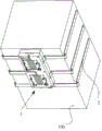
图1为本发明半导体制冷设备实施例的结构示意图;1 is a schematic structural diagram of an embodiment of a semiconductor refrigeration device of the present invention;
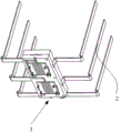
图2为本发明半导体制冷设备实施例中内胆与冷端散热器的组装图;Fig. 2 is the assembly diagram of the inner tank and the cold end radiator in the embodiment of the semiconductor refrigeration equipment of the present invention;
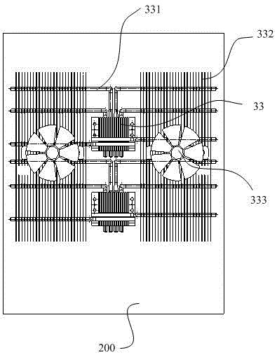
图3为本发明半导体制冷设备实施例中热端散热器的结构示意图;3 is a schematic structural diagram of a hot end radiator in an embodiment of the semiconductor refrigeration equipment of the present invention;
图4为本发明半导体制冷模组的结构示意图;4 is a schematic structural diagram of a semiconductor refrigeration module of the present invention;
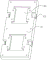
图5为本发明半导体制冷模组中第一隔热支架的正面结构示意图;5 is a schematic front view of the structure of the first heat insulating support in the semiconductor refrigeration module of the present invention;
图6为本发明半导体制冷模组中第一隔热支架的反面结构示意图;6 is a schematic view of the reverse structure of the first heat insulating support in the semiconductor refrigeration module of the present invention;
图7为本发明半导体制冷模组第二隔热支架的正面结构示意图;7 is a schematic front view of the structure of the second heat insulating support of the semiconductor refrigeration module of the present invention;
图8为本发明半导体制冷模组中第二隔热支架的反面结构示意图;8 is a schematic view of the reverse structure of the second heat insulating support in the semiconductor refrigeration module of the present invention;
图9为本发明半导体制冷模组中第一导热板的结构示意图;9 is a schematic structural diagram of a first heat conducting plate in the semiconductor refrigeration module of the present invention;
图10为本发明半导体制冷模组中第二导热板的结构示意图;10 is a schematic structural diagram of a second heat conducting plate in the semiconductor refrigeration module of the present invention;
图11为本发明半导体制冷模组的爆炸图。11 is an exploded view of the semiconductor refrigeration module of the present invention.
具体实施方式Detailed ways
为使本发明实施例的目的、技术方案和优点更加清楚,下面将结合本发明实施例中的附图,对本发明实施例中的技术方案进行清楚、完整地描述,显然,所描述的实施例是本发明一部分实施例,而不是全部的实施例。基于本发明中的实施例,本领域普通技术人员在没有做出创造性劳动前提下所获得的所有其他实施例,都属于本发明保护的范围。In order to make the purposes, technical solutions and advantages of the embodiments of the present invention clearer, the technical solutions in the embodiments of the present invention will be clearly and completely described below with reference to the accompanying drawings in the embodiments of the present invention. Obviously, the described embodiments These are some embodiments of the present invention, but not all embodiments. Based on the embodiments of the present invention, all other embodiments obtained by those of ordinary skill in the art without creative efforts shall fall within the protection scope of the present invention.
如图1-图3所示,本实施例半导体制冷设备,包括箱壳200和设置在所述箱壳中的内胆100,所述内胆100配置有半导体制冷模组,所述半导体制冷模组包括组装在一起的半导体制冷芯片、热端散热器和冷端散热器,所述冷端散热器包括冷端导热座和连接所述冷端导热座的第一热管2,所述第一热管2贴在所述内胆100上,所述热端散热器包括热端导热座33和连接所述热端导热座33的第二热管331,所述第二热管331上设置有多片散热翅片332,所述散热翅片332的一侧边设置有缺口结构,多个所述缺口结构形成安装凹槽,所述安装凹槽中设置有散热风扇333。As shown in FIGS. 1-3 , the semiconductor refrigeration equipment of this embodiment includes a
具体而言,本实施例半导体制冷设备中的热端导热座33吸收半导体制冷芯片热端面释放的热量并通过第二热管331传递至散热翅片332处,散热翅片332上设置缺口结构,多个散热翅片332上的缺口结构将形成用于安装散热风扇333的安装凹槽,使得散热风扇333嵌入在多片散热翅片332中,这样,散热风扇333运行过程中,散热风扇333吸入外界的冷空气后,冷空气将经由相邻两片散热翅片332之间形成的空间流动,从而使得冷空气与散热翅片332的表面接触进行热交换,因散热翅片332阵列方向与气流方向一致,有效的减小了气流阻力,换热效率更高,散热翅片332单位时间散热量更大。其中,散热风扇333可以为离心风机,离心风机沿其轴线方向将外界空气吸入并从散热翅片332之间形成的空气吹出。另外,为了便于安装散热风扇333,散热风扇333设置有风机支架3331,所述风机支架3331横跨在所述散热翅片332上,具体的,风机支架3331可以横跨多片散热翅片332,风机之间3331与散热翅片332通过螺栓固定,使得散热风扇333的组装。优选的,所述热端导热座33上设置有散热片(未图示),利用散热片进一步的快速散发热端导热座33的热量。Specifically, the hot-end heat-conducting
本实施例半导体制冷设备,通过在多个散热翅片中形成缺口结构,缺口结构形成用于安装散热风扇的安装凹槽,在实际使用过程中,散热风扇吸入的冷空气能够经由两个散热翅片之间形成的通道传输,从而使得冷空气能够最大程度的与翅片接触进行热交换,有效的减少风阻,提高散热效率,实现提高制冷设备的散热能力和制冷效率并降低能耗。In the semiconductor refrigeration equipment of this embodiment, a gap structure is formed in the plurality of heat dissipation fins, and the gap structure forms an installation groove for installing a heat dissipation fan. During actual use, the cold air sucked by the heat dissipation fan can pass through the two heat dissipation fins. The channels formed between the fins are transmitted, so that the cold air can contact the fins to the greatest extent for heat exchange, effectively reduce the wind resistance, improve the heat dissipation efficiency, improve the heat dissipation capacity and cooling efficiency of the refrigeration equipment, and reduce energy consumption.
进一步的,为了更有效的提高制冷效率,如图1-图11所示,半导体制冷模组还包括组装模块3,所述组装模块3包括第一隔热支架31和第二隔热支架32,所述第一隔热支架31的内表面上设置有第一凹槽311,所述第一凹槽311中开设有贯穿所述第一隔热支架31的安装孔312,所述第二隔热支架32的内表面设置有第二凹槽321,所述第一隔热支架31固定在所述第二隔热支架32上,所述第一凹槽311和所述第二凹槽321之间形成安装腔体,所述半导体制冷芯片1位于所述安装孔312中,所述冷端导热座34设置在所述安装腔体中并与所述半导体制冷芯片1的冷端面接触,所述热端导热座33设置在所述第一隔热支架31上并与所述半导体制冷芯片1的热端面接触,所述第一热管2连接所述冷端导热座34。Further, in order to more effectively improve the cooling efficiency, as shown in FIG. 1-FIG. 11, the semiconductor refrigeration module further includes an
具体而言,本实施例半导体制冷模组将半导体制冷芯片1嵌入在第一隔热支架31的安装孔312中,半导体制冷芯片1的外围被第一隔热支架31包裹住,并且,通过第一隔热支架31将热端导热座33和冷端导热座34间隔开,可以有效的减少热端导热座33和冷端导热座34之间产生的热传递量,从而减少冷端导热座34的冷量损失,与此同时,冷端导热座34包裹在由第一隔热支架31和第二隔热支架32形成的具有隔温功能的安装腔体中,冷端导热座34传导的半导体制冷芯片1产生的冷量能够最大限度的通过热管2快速的传递到所需要的区域,从而减少冷端导热座34自身冷量散失量,更有效的降低能耗提高制冷效率。Specifically, in the semiconductor refrigeration module of this embodiment, the semiconductor refrigeration chip 1 is embedded in the mounting
优选的,第一隔热支架31的外表面绕所述安装孔312设置有隔热槽313,所述隔热槽313中设置有隔热棉(未标记);所述半导体制冷芯片1的热端面向外凸出于所述第一隔热支架31的外表面。具体的,通过隔热槽313能够在半导体制冷芯片1的外围设置隔热棉,从而通过隔热棉形成的保温圈进一步的减少半导体制冷芯片1冷端面的冷量向外散失,同时,也可以减少半导体制冷芯片1热端面的热量进入到安装腔体中,最大限度的减少冷量的损失;而半导体制冷芯片1热端面略高出第一隔热支架31的外表面,一方面使得半导体制冷芯片1热端面与热端导热座33能够良好的接触传热,另一方面,半导体制冷芯片1热端面脱离出安装孔312,能够减少热量从安装孔312传入到安装腔体中,也可以有效的减少冷量的损失。其中,为了便于电路布线连接,第一隔热支架31的外表面还设置有布线槽314,所述布线槽314与所述安装孔312连通。另外,根据制冷设备的制冷量需要,本实施例半导体制冷模组包括多个所述半导体制冷芯片1,所述组装模块3配置有与所述半导体制冷芯片1对应的所述热端导热座33和所述冷端导热座34,并且,所述第一隔热支架31开设有与所述半导体制冷芯片1对应所述安装孔312。Preferably, the outer surface of the first
进一步的,为了更有效的减少因组装造成热端导热座33和冷端导热座34之间产生的热传递,冷端导热座34上设置有避让缺口340,所述第一隔热支架31、所述第二隔热支架32和所述热端导热座33上分别设置有通孔(未标记),螺栓35穿设在对应的所述通孔中,所述螺栓35穿过所述避让缺口340所形成的区域。具体的,在组装过程中,通过螺栓35将热端导热座33、第一隔热支架31、冷端导热座34和所述第二隔热支架32依次组装固定在一起,而螺栓35通过避让缺口340避让开冷端导热座34,从而可以避免热端导热座33和冷端导热座34之间通过螺栓35产生热交换。其中,所述第一隔热支架31的内表面设置有用于安装所述第一热管2的第一管槽316和第一管槽317,所述第二隔热支架32的边缘设置有用于所述第一热管2穿过的缺口或贯通孔322或第二管槽。具体的,热管2通过第一管槽316和第一管槽317与贯通孔322配合穿出组装模块3,以方便热管2布置在制冷设备的内胆100上。另外,为了便于快速定位安装热端导热座33,第一隔热支架31的外表面绕所述安装孔312的外侧设置有多块定位挡板315,所述热端导热座33设置在多块所述定位挡板315之间。在组装时,通过定位挡板315能够方便的定位安装热端导热座33,并确保热端导热座33能够准确的与半导体制冷芯片1接触良好。Further, in order to more effectively reduce the heat transfer between the hot-end heat-conducting
又进一步的,所述冷端导热座34包括连接在一起的第一导热板341和第二导热板342,所述第一热管2夹在所述第一导热板341和所述第二导热板342之间。具体的,第一导热板341的内表面开设有横向设置的第一安装槽3411,所述第二导热板342的内表面开设有纵向设置的第二安装槽3421,所述第一热管2分为横向扁平热管和纵向扁平热管,所述横向扁平热管设置在所述第一安装槽3411中,所述纵向扁平热管设置在所述第二安装槽3421中,并且,所述横向扁平热管与所述纵向扁平热管相互接触。具体的,采用扁平热管能够有效的增大热管与冷端导热座34的接触面积,同时,扁平热管还能够有效的增大与内胆100之间的接触面积,提供热交换效率。并且,横向扁平热管与所述纵向扁平热管相互接触,使得不同位置处的热管温度分布均匀,缩小温差提高均温性。Still further, the cold-end heat-conducting
通过采用两个隔热支架之间形成的安装腔体来安装冷端导热座,使得冷端导热座与热端导热座被隔热支架有效的隔热间隔开,从而可以大大降低冷端导热座与热端导热座之间产生的热交换量,有效的减少冷量的散失,以提高制冷设备的制冷效率并降低能耗。与此同时,半导体制冷芯片嵌在第一隔热支架的安装孔中,在确保半导体制冷芯片的冷端面与冷端导热座良好接触的同时,确保半导体制冷芯片的热端面与热端导热座良好接触,确保热量快速散发,提高使用可靠性。The cold-end heat-conducting seat is installed by using the installation cavity formed between the two heat-insulating brackets, so that the cold-end heat-conducting seat and the hot-end heat-conducting seat are effectively separated by the heat-insulating bracket, so that the cold-end heat-conducting seat can be greatly reduced. The amount of heat exchange with the heat transfer seat at the hot end can effectively reduce the loss of cooling capacity, so as to improve the cooling efficiency of the refrigeration equipment and reduce energy consumption. At the same time, the semiconductor refrigeration chip is embedded in the mounting hole of the first heat insulation bracket, which ensures good contact between the cold end surface of the semiconductor refrigeration chip and the cold end heat conduction seat, and ensures that the hot end surface of the semiconductor refrigeration chip and the hot end heat conduction seat are in good condition. Contact to ensure rapid heat dissipation and improve reliability.
最后应说明的是:以上实施例仅用以说明本发明的技术方案,而非对其限制;尽管参照前述实施例对本发明进行了详细的说明,本领域的普通技术人员应当理解:其依然可以对前述各实施例所记载的技术方案进行修改,或者对其中部分技术特征进行等同替换;而这些修改或者替换,并不使相应技术方案的本质脱离本发明个实施例技术方案的精神和范围。Finally, it should be noted that the above embodiments are only used to illustrate the technical solutions of the present invention, but not to limit them; although the present invention has been described in detail with reference to the foregoing embodiments, those of ordinary skill in the art should understand that it can still be The technical solutions described in the foregoing embodiments are modified, or some technical features thereof are equivalently replaced; and these modifications or replacements do not make the essence of the corresponding technical solutions deviate from the spirit and scope of the technical solutions of the embodiments of the present invention.
Claims (9)
Priority Applications (1)
| Application Number | Priority Date | Filing Date | Title |
|---|---|---|---|
| CN201710293549.8A CN108800703B (en) | 2017-04-28 | 2017-04-28 | Semiconductor refrigeration equipment |
Applications Claiming Priority (1)
| Application Number | Priority Date | Filing Date | Title |
|---|---|---|---|
| CN201710293549.8A CN108800703B (en) | 2017-04-28 | 2017-04-28 | Semiconductor refrigeration equipment |
Publications (2)
| Publication Number | Publication Date |
|---|---|
| CN108800703A CN108800703A (en) | 2018-11-13 |
| CN108800703B true CN108800703B (en) | 2020-12-15 |
Family
ID=64069112
Family Applications (1)
| Application Number | Title | Priority Date | Filing Date |
|---|---|---|---|
| CN201710293549.8A Active CN108800703B (en) | 2017-04-28 | 2017-04-28 | Semiconductor refrigeration equipment |
Country Status (1)
| Country | Link |
|---|---|
| CN (1) | CN108800703B (en) |
Families Citing this family (6)
| Publication number | Priority date | Publication date | Assignee | Title |
|---|---|---|---|---|
| CN111326487A (en) * | 2018-12-17 | 2020-06-23 | 青岛海尔智能技术研发有限公司 | Fin radiator and refrigeration cabinet machine |
| CN110749123A (en) * | 2019-10-10 | 2020-02-04 | 青岛海尔智能技术研发有限公司 | Radiator and refrigeration equipment |
| CN110749124A (en) * | 2019-10-10 | 2020-02-04 | 青岛海尔智能技术研发有限公司 | Radiator and refrigeration equipment |
| CN110749122A (en) * | 2019-10-10 | 2020-02-04 | 青岛海尔智能技术研发有限公司 | Radiator and refrigeration equipment |
| CN110749121B (en) * | 2019-10-10 | 2024-05-17 | 青岛海尔智能技术研发有限公司 | Method and device for controlling operation of semiconductor refrigeration equipment and refrigeration equipment |
| CN117405429A (en) * | 2023-10-23 | 2024-01-16 | 中国人民解放军海军工程大学 | A low-temperature performance testing device for multi-stage thermoelectric refrigerators working in Dewar vessels |
Citations (5)
| Publication number | Priority date | Publication date | Assignee | Title |
|---|---|---|---|---|
| CN200943973Y (en) * | 2006-08-15 | 2007-09-05 | 中山市柏迪半导体致冷设备有限公司 | Heat sinks for semiconductor refrigeration devices |
| CN203943523U (en) * | 2014-04-28 | 2014-11-19 | 广东新创意科技有限公司 | A kind of semiconductor refrigerating drinking water apparatus |
| CN204373476U (en) * | 2014-12-01 | 2015-06-03 | 青岛海尔特种电冰柜有限公司 | Heat abstractor and semiconductor refrigerating equipment |
| CN204693888U (en) * | 2015-05-29 | 2015-10-07 | 青岛海尔智能技术研发有限公司 | Heat abstractor and there is the semiconductor refrigerating box of this heat abstractor |
| CN105716315A (en) * | 2014-12-01 | 2016-06-29 | 青岛海尔特种电冰柜有限公司 | semiconductor refrigeration equipment |
-
2017
- 2017-04-28 CN CN201710293549.8A patent/CN108800703B/en active Active
Patent Citations (5)
| Publication number | Priority date | Publication date | Assignee | Title |
|---|---|---|---|---|
| CN200943973Y (en) * | 2006-08-15 | 2007-09-05 | 中山市柏迪半导体致冷设备有限公司 | Heat sinks for semiconductor refrigeration devices |
| CN203943523U (en) * | 2014-04-28 | 2014-11-19 | 广东新创意科技有限公司 | A kind of semiconductor refrigerating drinking water apparatus |
| CN204373476U (en) * | 2014-12-01 | 2015-06-03 | 青岛海尔特种电冰柜有限公司 | Heat abstractor and semiconductor refrigerating equipment |
| CN105716315A (en) * | 2014-12-01 | 2016-06-29 | 青岛海尔特种电冰柜有限公司 | semiconductor refrigeration equipment |
| CN204693888U (en) * | 2015-05-29 | 2015-10-07 | 青岛海尔智能技术研发有限公司 | Heat abstractor and there is the semiconductor refrigerating box of this heat abstractor |
Also Published As
| Publication number | Publication date |
|---|---|
| CN108800703A (en) | 2018-11-13 |
Similar Documents
| Publication | Publication Date | Title |
|---|---|---|
| CN108800656B (en) | Semiconductor refrigeration module and refrigeration equipment | |
| CN108800712B (en) | Multi-temperature zone semiconductor refrigeration equipment | |
| CN101610658B (en) | Heat dissipation device | |
| TWI525300B (en) | Composite heat sink assembly for power module | |
| CN108800655B (en) | Semiconductor refrigeration device | |
| CN108800703A (en) | Semiconductor refrigerating equipment | |
| CN204535494U (en) | A kind of many pedestals position heat exchanger | |
| CN209710561U (en) | Radiators and communication equipment | |
| CN108800711B (en) | Dual temperature zone solid state refrigeration equipment | |
| CN206249216U (en) | An electronic radiator | |
| CN217238762U (en) | Double-fan strong pressure type CPU radiator | |
| CN107645889A (en) | A kind of device and method to be radiated to optical module on veneer | |
| CN209857420U (en) | Semiconductor refrigeration equipment | |
| CN109600966B (en) | Heat radiator for can be used to solid-state formula direct current circuit breaker | |
| CN105466100A (en) | Heat exchanging device and semiconductor cooling refrigerator comprising same | |
| CN214891556U (en) | Cooling components, radiators and air conditioner outdoor units | |
| CN204390151U (en) | A kind of air-cooled heat-pipe radiator | |
| CN110749123A (en) | Radiator and refrigeration equipment | |
| CN213987398U (en) | Heat radiation structure and server | |
| CN211702710U (en) | Sealed cooling chassis | |
| CN210349818U (en) | Low flow resistance fin radiator | |
| CN109974331A (en) | A kind of semiconductor cooling device | |
| CN112099607A (en) | A cooling device based on big data cloud computing equipment | |
| CN114423245A (en) | Semiconductor cooling assembly and radiator | |
| CN216477586U (en) | Fast engine cylinder body dispels heat |
Legal Events
| Date | Code | Title | Description |
|---|---|---|---|
| PB01 | Publication | ||
| PB01 | Publication | ||
| SE01 | Entry into force of request for substantive examination | ||
| SE01 | Entry into force of request for substantive examination | ||
| GR01 | Patent grant | ||
| GR01 | Patent grant |