CN108733552B - A FPGA remote debugging system and remote debugging method - Google Patents
A FPGA remote debugging system and remote debugging method Download PDFInfo
- Publication number
- CN108733552B CN108733552B CN201710252578.XA CN201710252578A CN108733552B CN 108733552 B CN108733552 B CN 108733552B CN 201710252578 A CN201710252578 A CN 201710252578A CN 108733552 B CN108733552 B CN 108733552B
- Authority
- CN
- China
- Prior art keywords
- debugging
- target
- command
- fpga
- module
- Prior art date
- Legal status (The legal status is an assumption and is not a legal conclusion. Google has not performed a legal analysis and makes no representation as to the accuracy of the status listed.)
- Active
Links
Images


Classifications
-
- G—PHYSICS
- G06—COMPUTING OR CALCULATING; COUNTING
- G06F—ELECTRIC DIGITAL DATA PROCESSING
- G06F11/00—Error detection; Error correction; Monitoring
- G06F11/36—Prevention of errors by analysis, debugging or testing of software
- G06F11/3698—Environments for analysis, debugging or testing of software
-
- G—PHYSICS
- G06—COMPUTING OR CALCULATING; COUNTING
- G06F—ELECTRIC DIGITAL DATA PROCESSING
- G06F11/00—Error detection; Error correction; Monitoring
- G06F11/36—Prevention of errors by analysis, debugging or testing of software
- G06F11/3668—Testing of software
- G06F11/3672—Test management
- G06F11/3688—Test management for test execution, e.g. scheduling of test suites
-
- H—ELECTRICITY
- H04—ELECTRIC COMMUNICATION TECHNIQUE
- H04L—TRANSMISSION OF DIGITAL INFORMATION, e.g. TELEGRAPHIC COMMUNICATION
- H04L43/00—Arrangements for monitoring or testing data switching networks
- H04L43/50—Testing arrangements
-
- H—ELECTRICITY
- H04—ELECTRIC COMMUNICATION TECHNIQUE
- H04L—TRANSMISSION OF DIGITAL INFORMATION, e.g. TELEGRAPHIC COMMUNICATION
- H04L67/00—Network arrangements or protocols for supporting network services or applications
- H04L67/01—Protocols
- H04L67/12—Protocols specially adapted for proprietary or special-purpose networking environments, e.g. medical networks, sensor networks, networks in vehicles or remote metering networks
- H04L67/125—Protocols specially adapted for proprietary or special-purpose networking environments, e.g. medical networks, sensor networks, networks in vehicles or remote metering networks involving control of end-device applications over a network
-
- H—ELECTRICITY
- H04—ELECTRIC COMMUNICATION TECHNIQUE
- H04L—TRANSMISSION OF DIGITAL INFORMATION, e.g. TELEGRAPHIC COMMUNICATION
- H04L67/00—Network arrangements or protocols for supporting network services or applications
- H04L67/34—Network arrangements or protocols for supporting network services or applications involving the movement of software or configuration parameters
Landscapes
- Engineering & Computer Science (AREA)
- Theoretical Computer Science (AREA)
- Signal Processing (AREA)
- Computer Networks & Wireless Communication (AREA)
- Physics & Mathematics (AREA)
- General Physics & Mathematics (AREA)
- General Engineering & Computer Science (AREA)
- Quality & Reliability (AREA)
- Computer Hardware Design (AREA)
- Health & Medical Sciences (AREA)
- Computing Systems (AREA)
- General Health & Medical Sciences (AREA)
- Medical Informatics (AREA)
- Debugging And Monitoring (AREA)
Abstract
本发明公布了一种FPGA远程调试系统及远程调试方法,系统包括在调试主机上运行的调试客户端、在目标机上运行的调试服务器、用于存储目标系统信息的数据库服务器;客户端与服务器通过远程调试通信协议共同完成对FPGA的远程调试;数据库服务器存储目标系统信息表;调试客户端用于用户交互操作、显示信息、发送调试请求包、接收调试回应包;调试服务器用于获取目标系统信息、接收来自调试客户端的调试请求包、对调试请求包进行命令解析、形成调试回应包并发送回调试客户端。采用本发明技术方案,通过互联网对连接在计算机主机上的FPGA板级系统进行硬件代码的烧写和调试,简单易用,可提高开发调试效率。
The invention discloses an FPGA remote debugging system and a remote debugging method. The system includes a debugging client running on a debugging host, a debugging server running on a target computer, and a database server for storing target system information; The remote debugging communication protocol completes the remote debugging of the FPGA; the database server stores the target system information table; the debugging client is used for user interaction, displaying information, sending debugging request packets, and receiving debugging response packets; debugging server is used to obtain target system information , Receive the debug request packet from the debug client, perform command parsing on the debug request packet, form a debug response packet and send it back to the debug client. By adopting the technical scheme of the present invention, the hardware code programming and debugging of the FPGA board-level system connected to the computer host is carried out through the Internet, which is simple and easy to use, and can improve the development and debugging efficiency.
Description
技术领域technical field
本发明涉及FPGA(Field Programmable Gate Array,现场可编程门阵列)开发过程中的调试技术,具体涉及一种简单、易用的针对FPGA板级系统的远程调试系统及调试方法。The invention relates to a debugging technology in the development process of an FPGA (Field Programmable Gate Array, Field Programmable Gate Array), in particular to a simple and easy-to-use remote debugging system and a debugging method for an FPGA board-level system.
背景技术Background technique
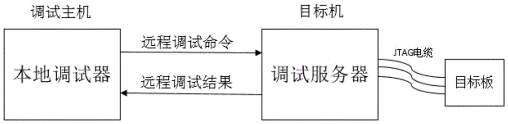
在现代数字设计中,FPGA因其资源丰富、使用灵活等优点,被广泛地使用。随着半导体技术发展,FPGA朝着可编程片上系统(system on programmable chip,SOPC)方向发展,系统高度集成,一些关键的信号只存在于芯片内部。芯片更多的引脚采用球栅阵列(ball grid arry,BGA)封装,引脚连接特性无法以传统的方法测试。对FPGA进行实时地分析和调试,是验证硬件逻辑正确性的重要手段,是系统硬件设计实现的最后环节。通常的调试方式需在现场将计算机主机用一根JTAG(Joint Test Action Group,联合测试工作组)接口的下载电缆线与要调试的FPGA器件连接,并在计算机主机上使用在线逻辑分析仪完成。In modern digital design, FPGA is widely used because of its abundant resources and flexible use. With the development of semiconductor technology, FPGA is developing towards a system on programmable chip (SOPC), the system is highly integrated, and some key signals only exist inside the chip. More pins of the chip are packaged in ball grid array (BGA), and the pin connection characteristics cannot be tested by traditional methods. Real-time analysis and debugging of FPGA is an important means to verify the correctness of hardware logic, and it is the last link of system hardware design and implementation. The usual debugging method needs to use a JTAG (Joint Test Action Group, Joint Test Action Group) interface download cable to connect the computer host to the FPGA device to be debugged on the spot, and use an online logic analyzer on the computer host to complete.
但是,在FPGA硬件系统开发中,通常由多人共同协作开发,而这些人可能分布在不同的地方。考虑到FPGA开发设备价格昂贵,为节约科研成本,不能保证人手一套FPGA开发设备。这时,对FPGA系统的调试变得非常不方便。因此,通过网络远程地对FPGA系统进行调试成为了一种需求。此外,在FPGA教学实验中,若能实现实验仪器设备网络化,使学生可以通过互联网远程地对实验室内的FPGA开发板进行操作,可以有效的提升调试验证的效率,节约时间成本,提高学生学习开发的积极性。However, in the development of FPGA hardware system, it is usually developed by multiple people, and these people may be distributed in different places. Considering the high price of FPGA development equipment, in order to save the cost of scientific research, a set of FPGA development equipment cannot be guaranteed. At this time, it becomes very inconvenient to debug the FPGA system. Therefore, it becomes a requirement to debug the FPGA system remotely through the network. In addition, in the FPGA teaching experiment, if the experimental equipment can be networked, so that students can remotely operate the FPGA development board in the laboratory through the Internet, which can effectively improve the efficiency of debugging and verification, save time and cost, and improve students Learning to develop positivity.
目前,已有的用于FPGA远程调试的装置方法如实用型专利(申请号20151103058.7)记载了一种FPGA/CPLD远程调试系统及方法,该技术存在的主要问题是只能观察管脚信号,不能观察芯片内部信号完成在线逻辑分析;另外,上述远程调试系统的结构复杂,需要额外的专用硬件电路装置,且目标机的网络参数需要用户手动配置。At present, the existing devices and methods for FPGA remote debugging, such as the utility patent (application number 20151103058.7), describe a FPGA/CPLD remote debugging system and method. The main problem of this technology is that it can only observe pin signals, and cannot Observing the internal signals of the chip to complete the online logic analysis; in addition, the structure of the above-mentioned remote debugging system is complex, requiring additional dedicated hardware circuit devices, and the network parameters of the target machine need to be manually configured by the user.
发明内容SUMMARY OF THE INVENTION
为了方便说明,本文约定:“TCL”表示工具命令语言,即Tool Command Language;“ILA”表示综合逻辑分析仪,即Integrated Logic Analyzer;Bit文件指FPGA设计的最终文件,用于配置FPGA的配置比特流,目标系统是指被调试的目标FPGA板及与其连接的目标机。For the convenience of description, this article agrees: "TCL" stands for Tool Command Language, namely Tool Command Language; "ILA" stands for Integrated Logic Analyzer, namely Integrated Logic Analyzer; Bit file refers to the final file of FPGA design, which is used to configure the configuration bits of FPGA Stream, the target system refers to the target FPGA board being debugged and the target computer connected to it.
针对现有技术存在的不足,本发明提供了一种简单、易用的FPGA远程调试系统及远程调试方法,采用本发明技术方案,可以通过互联网对连接在计算机主机上的FPGA板级系统进行硬件代码的烧写和调试。Aiming at the shortcomings of the prior art, the present invention provides a simple and easy-to-use FPGA remote debugging system and remote debugging method. By adopting the technical solution of the present invention, the hardware of the FPGA board-level system connected to the computer host can be performed through the Internet. Code programming and debugging.
本发明的原理是:目标机在数据库服务器上注册自己的系统参数和与之连接的FPGA板级系统参数,并定时检测IP地址是否发生变化;如果检测到IP地址发生变化则更新数据库中的相应记录。调试主机上运行的调试器从数据库中获取注册的目标机名字,根据用户选择的目标机名字获取目标机IP地址,然后与目标机建立TCP连接,将用户输入的控制指令和参数集组成调试请求包,发送给目标机;目标机收到调试请求包后解析并执行,然后将结果组成调试回应包,再通过TCP连接发送给调试主机;调试主机收到调试回应包,解析并展示在用户图形界面。The principle of the present invention is: the target machine registers its own system parameters and the FPGA board-level system parameters connected to it on the database server, and regularly detects whether the IP address changes; Record. The debugger running on the debugging host obtains the name of the registered target machine from the database, obtains the IP address of the target machine according to the name of the target machine selected by the user, and then establishes a TCP connection with the target machine, and composes the control command and parameter set input by the user into a debugging request package and send it to the target computer; the target computer parses and executes the debug request packet after receiving it, then composes the result into a debug response packet, and sends it to the debug host through the TCP connection; the debug host receives the debug response packet, parses and displays it on the user graph interface.
本发明提供的技术方案如下:The technical scheme provided by the present invention is as follows:
一种FPGA远程调试系统,针对FPGA平台进行远程调试,系统包括运行于调试主机的调试客户端、运行于目标机的调试服务器、远程调试通信协议、存储目标系统信息的数据库服务器;其中:An FPGA remote debugging system, which performs remote debugging on an FPGA platform, the system includes a debugging client running on a debugging host, a debugging server running on a target computer, a remote debugging communication protocol, and a database server storing target system information; wherein:
(1)所述调试客户端包括调试界面模块、目标系统参数获取模块、初始化模块和远程通信接口模块一;其中:(1) The debug client includes a debug interface module, a target system parameter acquisition module, an initialization module and a remote communication interface module one; wherein:
(1.1)所述调试界面模块用于:以图形界面的方式引导调试者输入参数、点击指令集按钮,接收用户的各种调试命令并形成远程调试请求包,解析调试回应包并将结果显示在用户图形界面;调试者输入参数包括目标机名字、目标FPAG板级系统参数及调试参数;所述目标FPGA板级系统参数包括FPGA板型号、FPGA板是否连接目标机;所述调试参数包括刷新频率、触发信号;(1.1) The debug interface module is used to: guide the debugger to input parameters, click the instruction set button in the form of a graphical interface, receive various debug commands from the user and form a remote debug request packet, parse the debug response packet and display the results in the User graphical interface; debugger input parameters include target machine name, target FPAG board-level system parameters and debugging parameters; the target FPGA board-level system parameters include FPGA board model, whether the FPGA board is connected to the target machine; The debugging parameters include refresh frequency , trigger signal;
指令集按钮对应的调试命令包括PROGRAM指令、TRIGGER指令集、TRIGGER SETUP指令和REFRESH RATE SETTING指令;PROGRAM指令用于将用户选择的Bit文件烧写进与目标机连接的FPGA板;所述TRIGGER指令集包括TRIGGER IMMEDIATELY指令、TRIGGERCONDITIONALLY指令和TRIGGER CIRCULARLY指令;TRIGGER IMMEDIATELY指令即立即触发,用于立即开始采样观察信号数值并以波形显示;TRIGGER CONDITIONALLY指令即条件触发,用于当满足触发信号条件时开始采样观察信号数值并以波形显示;TRIGGER CIRCULARLY指令即循环触发,用于循环不断的执行TRIGGER IMMEDIATELY指令和TRIGGER CONDITIONALLY指令,已一定的频率刷新显示波形;TRIGGER SETUP指令用于设置调试参数中的触发信号,包括触发信号的名字和满足触发条件的值;REFRESH RATE SETTING指令用于设置调试参数中的刷新频率,刷新频率是指循环触发是采样信号波形刷新的频率。The debugging commands corresponding to the command set button include PROGRAM command, TRIGGER command set, TRIGGER SETUP command and REFRESH RATE SETTING command; PROGRAM command is used to program the Bit file selected by the user into the FPGA board connected to the target machine; the TRIGGER command set Including TRIGGER IMMEDIATELY instruction, TRIGGERCONDITIONALLY instruction and TRIGGER CIRCULARLY instruction; TRIGGER IMMEDIATELY instruction triggers immediately, which is used to immediately start sampling and observing the signal value and display it as a waveform; TRIGGER CONDITIONALLY instruction is conditional triggering, which is used to start sampling and observation when the trigger signal conditions are met The signal value is displayed as a waveform; the TRIGGER CIRCULARLY command is a cyclic trigger, which is used to execute the TRIGGER IMMEDIATELY and TRIGGER CONDITIONALLY commands cyclically, and the displayed waveform has been refreshed at a certain frequency; the TRIGGER SETUP command is used to set the trigger signal in the debugging parameters, including The name of the trigger signal and the value that satisfies the trigger condition; the REFRESH RATE SETTING command is used to set the refresh frequency in the debugging parameters, and the refresh frequency refers to the frequency at which the cycle trigger is refreshed by the sampling signal waveform.
(1.2)所述目标系统参数获取模块用于获取目标机参数和目标FPGA板级系统参数,首先从数据库服务器中获取注册的目标系统名字,以多选框的形式展示在用户图形界面,然后根据用户选择的目标系统名字获取目标机IP地址、FPGA板级系统参数,并将获取的参数传给初始化模块。(1.2) The target system parameter acquisition module is used to obtain the target machine parameters and the target FPGA board-level system parameters. First, the registered target system name is obtained from the database server, and displayed in the user graphical interface in the form of a multi-select box, and then according to the The target system name selected by the user obtains the target machine IP address and FPGA board-level system parameters, and transfers the obtained parameters to the initialization module.
(1.3)所述初始化模块接收目标系统参数获取模块传来的参数,根据目标机IP地址向目标机发起TCP连接请求,并将目标FPGA板级系统参数显示在调试界面。用户可以根据参数FPGA板型号,判断该板是否适合烧写所选的Bit文件,根据参数FPGA板是否连接目标机,判断FPGA板是否连接到目标机并上电。(1.3) The initialization module receives the parameters from the target system parameter acquisition module, initiates a TCP connection request to the target machine according to the target machine IP address, and displays the target FPGA board-level system parameters on the debugging interface. The user can judge whether the board is suitable for programming the selected Bit file according to the parameter FPGA board model, and judge whether the FPGA board is connected to the target machine and powered on according to whether the parameter FPGA board is connected to the target machine.
(1.4)所述远程通信接口模块一用于:将所述指令集中的PROGRAM指令、TRIGGER指令集、TRIGGER SETUP指令和REFRESH RATE SETTING指令及其所需参数集,通过互联网发送至目标机;接收目标机返回的调试回应包,并传递给调试界面模块。(1.4) The remote communication interface module 1 is used to: send the PROGRAM command, TRIGGER command set, TRIGGER SETUP command, REFRESH RATE SETTING command and their required parameter sets in the command set to the target machine through the Internet; receive the target machine The debug response packet returned by the machine is passed to the debug interface module.
(2)所述调试服务器包括目标系统信息更新模块、远程通信接口模块二、调试命令解析模块、Bit文件烧写模块、信号采集模块和设置模块。其中:(2) The debugging server includes a target system information update module, a remote communication interface module 2, a debugging command parsing module, a Bit file programming module, a signal acquisition module and a setting module. in:
(2.1)所述目标系统信息更新模块用于:获取目标机登录用户名,将其作为目标系统名字;定时获取目标机IP地址和与目标机连接的目标FPGA板级系统参数;如果目标系统名字首次出现,则在目标系统信息表中插入一条记录;如果目标系统名字已注册过,检查IP地址和FPGA板级系统参数是否有变化,有变化则更新该条记录。(2.1) the described target system information update module is used for: obtain the target machine login user name, take it as the target system name; regularly obtain the target machine IP address and the target FPGA board-level system parameter connected with the target machine; if the target system name If it appears for the first time, insert a record into the target system information table; if the target system name has been registered, check whether the IP address and FPGA board-level system parameters have changed, and update the record if there is a change.
(2.2)所述通信接口模块二用于:接收来自调试客户端的调试请求包,并将调试请求包发送至命令解析模块;将调试回应包发送给调试主机。(2.2) The second communication interface module is used for: receiving the debugging request package from the debugging client, sending the debugging request package to the command parsing module, and sending the debugging response package to the debugging host.
(2.3)所述调试命令解析模块用于:解析出接收到的调试请求包中调试命令,并根据命令类型通知下行模块响应所述指令集中的PROGRAM指令、TRIGGER指令集、TRIGGERSETUP指令和REFRESH RATE SETTING指令;其中PROGRAM指令由Bit文件烧写模块响应,TRIGGER指令集中的TRIGGER IMMED,TELY指令、TRIGGER CONDITIONALLY指令和TRIGGERCIRCULARLY指令由信号采集模块响应,TRIGGER SETUP指令和REFRESH RATE SETTING指令由设置模块响应;收到下行模块反馈结果后组成调试回应包并发送至所述通信模块二。(2.3) The debugging command parsing module is used to: parse out the debugging command in the received debugging request packet, and notify the downstream module to respond to the PROGRAM command, TRIGGER command set, TRIGGERSETUP command and REFRESH RATE SETTING in the command set according to the command type command; the PROGRAM command is responded by the Bit file programming module, the TRIGGER IMMED, TELY command, TRIGGER CONDITIONALLY command and TRIGGERCIRCULARLY command in the TRIGGER command set are responded by the signal acquisition module, and the TRIGGER SETUP command and REFRESH RATE SETTING command are responded by the setting module; received After the downlink module feeds back the results, a debugging response packet is formed and sent to the second communication module.
(2.4)所述Bit文件烧写模块用于:执行PROGRAM指令,控制目标机将用户所选择的Bit文件烧写至目标FPGA板,并将烧写的结果反馈给命令解析模块。(2.4) The Bit file programming module is used for: executing the PROGRAM instruction, controlling the target computer to program the Bit file selected by the user to the target FPGA board, and feeding back the programming result to the command parsing module.
(2.5)所述信号采集模块用于:执行TRIGGER指令集,控制目标机对观察信号进行采样并生成实时信号数据的ILA格式文件,并将该文件的全路径名反馈给命令解析模块。(2.5) The signal acquisition module is used for: executing the TRIGGER instruction set, controlling the target machine to sample the observation signal and generating an ILA format file of real-time signal data, and feeding back the full pathname of the file to the command parsing module.
(2.6)所述设置模块用于:执行TRIGGER SETUP指令和REFRESH RATE SETTING指令,其中TRIGGER SETUP指令完成触发信号的名字和满足触发条件的值的设置,REFRESHRATE SETTING命令完成循环触发波形刷新频率的设置。(2.6) The setting module is used to: execute the TRIGGER SETUP command and the REFRESH RATE SETTING command, wherein the TRIGGER SETUP command completes the setting of the name of the trigger signal and the value that meets the trigger condition, and the REFRESHRATE SETTING command completes the setting of the refresh frequency of the cyclic trigger waveform.
(3)所述远程通信协议定义了调试主机上的调试客户端与目标机上的调试服务器共同完成远程调试的协作方式、通信方式及内容。调试客户端发送调试请求包并接收调试回应包,调试服务器接收调试请求包并发送包含调试结果的回应包。调试请求包内容包括调试命令类型和调试命令参数集,调试回应包内容包括调试命令类型和调试命令结果集。(3) The remote communication protocol defines the cooperation mode, communication mode and content for the debugging client on the debugging host and the debugging server on the target computer to complete the remote debugging together. The debugging client sends a debugging request packet and receives a debugging response packet, and the debugging server receives the debugging request packet and sends a response packet containing the debugging result. The content of the debug request packet includes the type of debug command and the parameter set of the debug command, and the content of the debug response packet includes the type of the debug command and the result set of the debug command.
(4)所述存储目标系统信息的数据库服务器用于存储目标系统信息表;通过所述调试服务器中的目标系统信息更新模块更新该表记录,通过所述调试客户端的目标系统参数获取模块从该表读取目标系统参数。该表的结构为(目标机id、目标系统名字、目标机IP地址、目标FPGA板型号、目标FPGA板是否连接目标机)。(4) The database server storing the target system information is used to store the target system information table; the table record is updated by the target system information update module in the debugging server, and the target system parameter acquisition module of the debugging client is used to obtain the target system information from the table. The table reads the target system parameters. The structure of the table is (target machine id, target system name, target machine IP address, target FPGA board model, whether the target FPGA board is connected to the target machine).
本发明的有益效果为:The beneficial effects of the present invention are:
本发明提供一种FPGA远程调试系统,针对FPGA平台进行远程调试,系统包括运行于调试主机的调试客户端、运行于目标主机的调试服务器、远程调试通信协议、存储目标系统信息的数据库服务器。与现有技术相比,本发明具有以下技术优势:The invention provides an FPGA remote debugging system, which performs remote debugging on an FPGA platform. The system includes a debugging client running on a debugging host, a debugging server running on a target host, a remote debugging communication protocol, and a database server storing target system information. Compared with the prior art, the present invention has the following technical advantages:
(一)本发明将传统的目标FPGA板级系统现场调试方法网络化,使得调试人员可通过互联网远程地对目标FPGA板级系统进行调试,方便了远程对FPGA板进行调试,提高了开发调试的效率;(1) The present invention networkizes the traditional on-site debugging method of the target FPGA board-level system, so that the debugging personnel can remotely debug the target FPGA board-level system through the Internet, which facilitates the remote debugging of the FPGA board and improves the development and debugging process. efficiency;
(二)本发明只需要像本地调试一样将目标FPGA板级系统通过JTAG连接到PC上,不需要其他额外的硬件电路装置,结构简明;(2) The present invention only needs to connect the target FPGA board-level system to the PC through JTAG like local debugging, does not require other additional hardware circuit devices, and has a concise structure;
(三)本发明可以观察芯片内部信号,能够实现跟本地调试一样的在线逻辑分析,更加准确地验证硬件逻辑正确性。(3) The present invention can observe the internal signals of the chip, realize the same online logic analysis as local debugging, and more accurately verify the correctness of hardware logic.
附图说明Description of drawings
图1为本发明提供的FPGA远程调试系统的组成结构框图。FIG. 1 is a structural block diagram of the FPGA remote debugging system provided by the present invention.
图2为本发明提供的FPGA远程调试系统的结构框图。FIG. 2 is a structural block diagram of the FPGA remote debugging system provided by the present invention.
具体实施方式Detailed ways
下面结合附图,通过实施例进一步描述本发明,但不以任何方式限制本发明的范围。Below in conjunction with the accompanying drawings, the present invention is further described by means of embodiments, but the scope of the present invention is not limited in any way.
本发明提供一种FPGA远程调试系统,针对FPGA平台进行远程调试,系统包括运行于调试主机的调试客户端、运行于目标主机的调试服务器、远程调试通信协议、存储目标系统信息的数据库服务器。图2为本发明提供的FPGA远程调试系统的结构框图。图1具体表示了系统的组成结构。调试客户端包括调试界面模块、目标系统参数获取模块、初始化模块和远程通信接口模块一;调试服务器包括目标系统信息更新模块、远程通信接口模块二、调试命令解析模块、Bit文件烧写模块、信号采集模块和设置模块;远程通信协议包括调试主机上的调试客户端与目标机上的调试服务器共同完成远程调试的协作方式、通信方式及内容;数据库服务器存储目标系统信息表。The invention provides an FPGA remote debugging system, which performs remote debugging on an FPGA platform. The system includes a debugging client running on a debugging host, a debugging server running on a target host, a remote debugging communication protocol, and a database server storing target system information. FIG. 2 is a structural block diagram of the FPGA remote debugging system provided by the present invention. Figure 1 specifically shows the composition of the system. The debugging client includes a debugging interface module, a target system parameter acquisition module, an initialization module and a remote communication interface module 1; the debugging server includes a target system information update module, a remote communication interface module 2, a debugging command parsing module, a Bit file programming module, and a signal The acquisition module and the setting module; the remote communication protocol includes the cooperation mode, communication mode and content of the debugging client on the debugging host and the debugging server on the target computer to complete the remote debugging together; the database server stores the target system information table.
利用上述FPGA远程调试系统,可通过以下具体步骤实现针对FPGA的远程调试:Using the above-mentioned FPGA remote debugging system, the remote debugging for FPGA can be realized through the following specific steps:
(1)通过目标系统信息更新模块获取目标机的登录用户名和IP地址、目标板级系统的型号以及连接状态,将这些信息存储到数据库服务器的目标系统信息表里;此后,会定时获取目标机IP地址和目标板级系统连接状态,如果这两个参数发生变化则更新目标系统信息表中的相应记录。目标系统信息表的结构为(目标系统id、目标系统名字、目标机IP地址、目标FPGA板型号、目标FPGA板是否连接目标机)。(1) Obtain the login user name and IP address of the target machine, the model and connection status of the target board-level system through the target system information update module, and store these information in the target system information table of the database server; after that, the target machine will be obtained regularly. IP address and target board-level system connection status, if these two parameters change, update the corresponding record in the target system information table. The structure of the target system information table is (target system id, target system name, target machine IP address, target FPGA board model, whether the target FPGA board is connected to the target machine).
(2)通过目标系统参数获取模块,首先从数据库服务器中获取所有目标系统的名字,在调试界面上以多选框的形式展示;然后根据用户选择的目标系统名字获取对应的目标机IP地址、目标FPGA开发板型号以及与目标机的连接状态,并将些参数传给调试客户端的初始化模块。(2) Through the target system parameter acquisition module, first obtain the names of all target systems from the database server, and display them in the form of multiple selection boxes on the debugging interface; then obtain the corresponding target machine IP address according to the target system name selected by the user, The model of the target FPGA development board and the connection status with the target machine, and pass these parameters to the initialization module of the debug client.
(3)初始化模块接收到目标系统参数获取模块传来的参数,根据参数目标机IP地址与目标机建立TCP连接,将参数目标FPGA开发板型号及与目标机的连接状态显示到调试界面上。参数FPGA板型号用于判断该板是否适合烧写所选的Bit文件,参数FPGA板是否连接目标机用于判断FPGA板是否连接到目标机并上电。(3) The initialization module receives the parameters from the target system parameter acquisition module, establishes a TCP connection with the target machine according to the parameter target machine IP address, and displays the parameter target FPGA development board model and the connection status with the target machine on the debugging interface. The parameter FPGA board model is used to judge whether the board is suitable for programming the selected Bit file, and the parameter FPGA board is connected to the target machine is used to judge whether the FPGA board is connected to the target machine and powered on.
(4)通过调试界面引导用户通过按钮输入调试指令,如果该指令需要参数,引导用户输入该指令需要的参数,形成调试请求包,发送至远程通信接口模块一。(4) Guide the user to input the debugging command through the button through the debugging interface. If the command requires parameters, guide the user to input the parameters required by the command to form a debugging request package and send it to the remote communication interface module 1.
(5)远程通信接口模块一通过TCP连接将调试请求包发送至目标机。(5) The remote communication interface module 1 sends the debugging request packet to the target computer through the TCP connection.
(6)远程通信接口模块二接收调试主机发送来的调试请求包;(6) The second remote communication interface module receives the debugging request packet sent by the debugging host;
(7)通过调试命令解析模块解析调试请求包,解析出调试命令类型和参数集,根据命令类型将命令类型和参数集传到相应的模块;其中PROGRAM命令对应Bit文件烧写模块,TRIGGER指令集对应采集信号模块,TRIGGER SETUP和REFRESH RATE SETTING指令对应调制服务器的设置模块。(7) Parse the debug request package through the debug command parsing module, parse out the debug command type and parameter set, and transmit the command type and parameter set to the corresponding module according to the command type; the PROGRAM command corresponds to the Bit file programming module, and the TRIGGER instruction set Corresponding to the acquisition signal module, the TRIGGER SETUP and REFRESH RATE SETTING commands correspond to the setting module of the modulation server.
(8)通过Bit文件烧写模块执行烧写Bit文件的TCL脚本,将指定Bit文件烧写到目标FPGA开发板上,获取TCL脚本执行的结果,如果烧写完成,结果是烧写成功;如果烧写发生错误,结果是错误信息;通过信号采集模块执行实时采样观察信号数值并生成相应ILA格式文件的TCL脚本。通过设置模块配置触发信号和触发模式,配置触发信号包括配置触发信号的名字和触发信号的值,刷新频率的取值通常为整百,比如500。(8) Execute the TCL script for programming the Bit file through the Bit file programming module, program the specified Bit file to the target FPGA development board, and obtain the execution result of the TCL script. If the programming is completed, the result is that the programming is successful; if There is an error in programming, and the result is an error message; through the signal acquisition module, real-time sampling is performed to observe the signal value and generate the TCL script of the corresponding ILA format file. Configure the trigger signal and trigger mode by setting the module. Configuring the trigger signal includes configuring the name of the trigger signal and the value of the trigger signal. The value of the refresh frequency is usually a whole hundred, such as 500.
(9)通过调试命令解析模块接收调试命令执行结果,形成调试回应包。(9) Receive the execution result of the debug command through the debug command parsing module, and form a debug response package.
(10)远程通信模块二通过TCP连接将调试回应包发送至调试主机。(10) The second remote communication module sends the debugging response packet to the debugging host through the TCP connection.
(11)远程通信模块一接收调试回应包。(11) The remote communication module receives the debugging response packet.
(12)通过调试界面模块解析调试回应包并将结果展示到用户图形界面上,对于PROGRAM指令直接显示结果即可,对于TRIGGER指令集需要将采集信号数值的文件解析后以波形的形式显示。(12) Analyze the debugging response package through the debugging interface module and display the results on the user graphical interface. For the PROGRAM command, the results can be displayed directly. For the TRIGGER command set, the file of the collected signal values needs to be parsed and displayed in the form of waveforms.
下面通过实施例对本发明做进一步说明,但不限于此。The present invention will be further described below through examples, but not limited thereto.
为了简化说明,以下实施例统一假定用户已经选好要调试的目标系统,调试主机与目标机之间建立起TCP连接。In order to simplify the description, the following embodiments uniformly assume that the user has selected the target system to be debugged, and a TCP connection is established between the debug host and the target computer.
实施例一:烧写Bit文件到目标FPGA开发板,步骤如下:Example 1: Burn the Bit file to the target FPGA development board, the steps are as follows:
(1)调试者在调试界面上点击“选择文件”按钮,在弹出的文件对话框里选择将要烧写的Bit文件。(1) The debugger clicks the "Select File" button on the debugging interface, and selects the Bit file to be programmed in the pop-up file dialog box.
(2)调试者在调试界面点击“烧写”按钮,调试界面模块将指令类型PROGAMM和包括文件名、文件大小,文件内容的参数集组成调试请求包发送至所述远程通信模块一。(2) The debugger clicks the "programming" button on the debugging interface, and the debugging interface module sends the command type PROGAMM and the parameter set including the file name, file size, and file content to form a debugging request package and send it to the remote communication module 1.
(3)远程通信模块一收到调试请求包,通过TCP连接将调试请求包发送至目标机并等待回应包。(3) Once the remote communication module receives the debug request packet, it sends the debug request packet to the target computer through the TCP connection and waits for the response packet.
(4)远程通信模块二接收调试请求包,并将调试请求包发送至所述命令解析模块。(4) The second remote communication module receives the debugging request packet, and sends the debugging request packet to the command parsing module.
(5)命令解析模块解析调试请求包,解析出指令类型为PROGRAM指令,然后将参数集发送至Bit文件烧写模块。(5) The command parsing module parses the debugging request packet, parses the instruction type as PROGRAM instruction, and then sends the parameter set to the Bit file programming module.
(6)Bit文件烧写模块首先接收Bit文件,存放在本地默认路径下,然后将包含全路径的Bit文件名作为参数传入烧写Bit文件的TCL脚本,并执行该脚本。当脚本执行结束后,将脚本执行的结果发送至所诉命令解析模块,如果脚本正确执行,则结果为“烧写成功”,否则结果为错误信息。(6) The Bit file programming module first receives the Bit file and stores it in the local default path, and then passes the Bit file name containing the full path as a parameter to the TCL script for programming the Bit file, and executes the script. After the script is executed, the result of the script execution is sent to the command parsing module. If the script is executed correctly, the result is "programming successful", otherwise the result is an error message.
(7)命令解析模块收到烧写Bit文件的结果,将其与指令类型PROGRAM组成调试回应包发送至所述远程通信模块二。(7) The command parsing module receives the result of programming the Bit file, forms a debugging response packet with the command type PROGRAM and sends it to the remote communication module two.
(8)远程通信模块二收到调试回应包,通过TCP连接将调试回应包发送至调试主机。(8) The remote communication module 2 receives the debugging response packet, and sends the debugging response packet to the debugging host through the TCP connection.
(9)远程通信模块一接收调试回应包,并将调试回应包发送至所述调试界面模块。(9) The remote communication module receives the debugging response packet, and sends the debugging response packet to the debugging interface module.
(10)调试界面模块收到调试回应包,解析出PROGRAM指令和烧写Bit文件结果,并将结果显示到“烧写结果”文本框中。(10) The debugging interface module receives the debugging response package, parses out the PROGRAM command and the result of programming the Bit file, and displays the result in the "programming result" text box.
实施例二:立即采集目标FPGA开发板上观察的信号,步骤如下:Embodiment 2: Immediately collect the signal observed on the target FPGA development board, the steps are as follows:
(1)调试者在调试界面上点击“立即触发”按钮,调试界面模块将指令类型TRIGGERIMMEDIATELY和空的参数集组成调试请求包发送至所述远程通信模块一。(1) The debugger clicks the "trigger immediately" button on the debugging interface, and the debugging interface module forms a debugging request packet composed of the instruction type TRIGGERIMMEDIATELY and an empty parameter set and sends it to the remote communication module 1.
(2)远程通信模块一收到调试请求包,通过TCP连接将调试请求包发送至目标机并等待回应包。(2) Once the remote communication module receives the debug request packet, it sends the debug request packet to the target computer through the TCP connection and waits for the response packet.
(3)远程通信模块二接收调试请求包,并将调试请求包发送至所述命令解析模块。(3) The second remote communication module receives the debugging request packet, and sends the debugging request packet to the command parsing module.
(4)命令解析模块解析调试请求包,解析出指令类型为TRIGGER IMMEDIATELY指令,并将指令发送至信号采集模块。(4) The command parsing module parses the debugging request packet, parses the instruction type as the TRIGGER IMMEDIATELY instruction, and sends the instruction to the signal acquisition module.
(5)信号采集模块接收到TRIGGER IMMEDIATELY指令,控制目标机执行立即采集观察信号数值并生成ILA文件的TCL脚本,并将生成的ILA文件全路径名发送至命令解析模块。(5) The signal acquisition module receives the TRIGGER IMMEDIATELY command, controls the target computer to execute the TCL script that immediately collects the observed signal value and generates the ILA file, and sends the full path name of the generated ILA file to the command parsing module.
(6)命令解析模块收到TRIGGER IMMEDIATELY指令执行结果,获取ILA文件大小、内容,同ILA文件名组成结果集,再将指令类型TRIGGER IMMEDIATELY和结果集组成调试回应包发送至远程通信模块二。(6) The command parsing module receives the execution result of the TRIGGER IMMEDIATELY command, obtains the size and content of the ILA file, forms a result set with the ILA file name, and then forms a debugging response packet with the command type TRIGGER IMMEDIATELY and the result set and sends it to the remote communication module 2.
(7)远程通信模块二收到调试回应包,通过TCP连接将调试回应包发送至调试主机。(7) The remote communication module 2 receives the debugging response packet, and sends the debugging response packet to the debugging host through the TCP connection.
(8)远程通信模块一接收调试回应包,并将调试回应包发送至所述调试界面模块。(8) The remote communication module receives the debugging response packet, and sends the debugging response packet to the debugging interface module.
(9)调试界面收到调试回应包,解析出指令类型TRIGGER IMMEDIATELY和结果集,首先接收ILA文件,然后解析ILA文件将观察信号数值以波形的形式展示与调试界面。(9) The debugging interface receives the debugging response package, parses the instruction type TRIGGER IMMEDIATELY and the result set, first receives the ILA file, and then parses the ILA file to display the observed signal values in the form of waveforms and the debugging interface.
需要注意的是,公布实施例的目的在于帮助进一步理解本发明,但是本领域的技术人员可以理解:在不脱离本发明及所附权利要求的精神和范围内,各种替换和修改都是可能的。因此,本发明不应局限于实施例所公开的内容,本发明要求保护的范围以权利要求书界定的范围为准。It should be noted that the purpose of publishing the embodiments is to help further understanding of the present invention, but those skilled in the art can understand that various replacements and modifications are possible without departing from the spirit and scope of the present invention and the appended claims of. Therefore, the present invention should not be limited to the contents disclosed in the embodiments, and the scope of protection of the present invention shall be subject to the scope defined by the claims.
Claims (9)
Priority Applications (1)
| Application Number | Priority Date | Filing Date | Title |
|---|---|---|---|
| CN201710252578.XA CN108733552B (en) | 2017-04-18 | 2017-04-18 | A FPGA remote debugging system and remote debugging method |
Applications Claiming Priority (1)
| Application Number | Priority Date | Filing Date | Title |
|---|---|---|---|
| CN201710252578.XA CN108733552B (en) | 2017-04-18 | 2017-04-18 | A FPGA remote debugging system and remote debugging method |
Publications (2)
| Publication Number | Publication Date |
|---|---|
| CN108733552A CN108733552A (en) | 2018-11-02 |
| CN108733552B true CN108733552B (en) | 2020-12-22 |
Family
ID=63925120
Family Applications (1)
| Application Number | Title | Priority Date | Filing Date |
|---|---|---|---|
| CN201710252578.XA Active CN108733552B (en) | 2017-04-18 | 2017-04-18 | A FPGA remote debugging system and remote debugging method |
Country Status (1)
| Country | Link |
|---|---|
| CN (1) | CN108733552B (en) |
Families Citing this family (14)
| Publication number | Priority date | Publication date | Assignee | Title |
|---|---|---|---|---|
| CN109861981A (en) * | 2018-12-28 | 2019-06-07 | 中科院计算技术研究所南京移动通信与计算创新研究院 | A signal frequency conversion sampling test control method, system, device and storage medium |
| CN109710479B (en) * | 2018-12-30 | 2021-05-18 | 联想(北京)有限公司 | Processing method, first device and second device |
| CN109815135A (en) * | 2018-12-31 | 2019-05-28 | 深圳市越疆科技有限公司 | A kind of monitoring method, device and the intelligent terminal of robot program's operating status |
| CN112015434A (en) * | 2019-05-29 | 2020-12-01 | 惠州拓邦电气技术有限公司 | Remote upgrading debugging control method, system, device and storage medium |
| CN110750402A (en) * | 2019-10-16 | 2020-02-04 | 深圳安时达电子服务有限公司 | Commissioning devices and remote commissioning systems |
| CN110806976B (en) * | 2019-10-24 | 2022-03-22 | 青岛英泰软件技术有限公司 | Method for remotely pushing shell and CMD (command-to-command) commands |
| CN110853325A (en) * | 2019-11-27 | 2020-02-28 | 瀚颐(上海)汽车电子科技有限公司 | Automobile wireless debugger, automobile wireless debugging system and method |
| CN111123084B (en) * | 2019-12-11 | 2022-03-01 | 中国电子科技集团公司第二十研究所 | A Fast Test Method for Digital Circuits Based on TCL Language |
| CN111487519B (en) * | 2020-04-07 | 2024-05-07 | 长江存储科技有限责任公司 | Test system and method |
| CN113656236B (en) * | 2020-05-12 | 2024-05-28 | 大唐移动通信设备有限公司 | Data processing method and device |
| CN111813702B (en) * | 2020-09-09 | 2020-12-22 | 鹏城实验室 | Debugging system, debugging method, apparatus, and computer-readable storage medium |
| CN112148617A (en) * | 2020-10-09 | 2020-12-29 | 中国科学技术大学 | A Waveform Sampling Debugging Method for Remote Experiment Platform |
| CN112231160A (en) * | 2020-10-16 | 2021-01-15 | 上海国微思尔芯技术股份有限公司 | FPGA board dynamic debugging method and FPGA board dynamic debugging device |
| CN113176953B (en) * | 2021-04-21 | 2024-08-06 | 北京锐达仪表有限公司 | On-site debugging terminal, instrument remote debugging system, instrument debugging method and readable storage medium |
Citations (2)
| Publication number | Priority date | Publication date | Assignee | Title |
|---|---|---|---|---|
| CN101413990A (en) * | 2008-12-03 | 2009-04-22 | 北京大学 | Method and system for testing on site programmable gate array |
| CN102332307A (en) * | 2011-07-28 | 2012-01-25 | 中国空间技术研究院 | SRAM type FPGA single event effect test system and method |
Family Cites Families (3)
| Publication number | Priority date | Publication date | Assignee | Title |
|---|---|---|---|---|
| CN101334766B (en) * | 2008-06-30 | 2011-05-11 | 东软飞利浦医疗设备系统有限责任公司 | Paralleling microprocessor and its realization method |
| ITTO20130974A1 (en) * | 2013-11-29 | 2015-05-30 | Magneti Marelli Spa | SYSTEM FOR TESTING THE WIRELESS INTERACTION BETWEEN AN AUDIO SIGNAL REPRODUCTION SYSTEM AND A MOBILE PHONE, ITS PROCEDURE AND IT PRODUCT |
| CN105718339B (en) * | 2015-12-31 | 2019-02-05 | 山东大学 | A FPGA/CPLD remote debugging system and method |
-
2017
- 2017-04-18 CN CN201710252578.XA patent/CN108733552B/en active Active
Patent Citations (2)
| Publication number | Priority date | Publication date | Assignee | Title |
|---|---|---|---|---|
| CN101413990A (en) * | 2008-12-03 | 2009-04-22 | 北京大学 | Method and system for testing on site programmable gate array |
| CN102332307A (en) * | 2011-07-28 | 2012-01-25 | 中国空间技术研究院 | SRAM type FPGA single event effect test system and method |
Also Published As
| Publication number | Publication date |
|---|---|
| CN108733552A (en) | 2018-11-02 |
Similar Documents
| Publication | Publication Date | Title |
|---|---|---|
| CN108733552B (en) | A FPGA remote debugging system and remote debugging method | |
| CN103812726B (en) | Automated testing method and device for data communication equipment | |
| CN101478449B (en) | A protocol automatic testing method and system thereof | |
| CN106209515B (en) | Access network equipment automated test system | |
| CN104731566B (en) | Integrated Development Environment test device, method and system | |
| JP2018010638A5 (en) | ||
| CN101241466A (en) | Embedded software testing method and system | |
| JP7665293B2 (en) | Test and measurement system and method for testing device under test | |
| CN101316196B (en) | A Realization Method and Device for Simulating and Testing Services on a Distributed Platform | |
| CN105718339A (en) | FPGA/CPLD remote debugging system and method | |
| CN106021101B (en) | The method and device that mobile terminal is tested | |
| CN106897207A (en) | Ui testing method and apparatus | |
| CN105787164A (en) | Debugging method and system for programmable logic device | |
| CN112882876A (en) | PLD device remote debugging and configuration system | |
| CN108228454B (en) | Electromechanical product software reliability evaluation method based on environmental fault injection | |
| CN112685285A (en) | User interface test case generation method and device | |
| CN110568339A (en) | Instrument automatic testing system and method based on Internet of things | |
| CN106776329B (en) | Debugging method and debugging equipment of energy storage converter | |
| CN117061371A (en) | Test methods and systems for energy products | |
| CN106325262B (en) | A kind of interface data generation system and method for Member Systems and onboard maintenance system | |
| CN114816980A (en) | A kind of automatic test device and method for embedded communication system | |
| CN108829591A (en) | A kind of synergic debugging system and method based on Web | |
| CN121070806B (en) | A website testing method, device, and medium based on multi-agent systems | |
| CN113010358A (en) | LTPB (Low temperature pluggable) bus detection device applied to avionics system and method for testing flow description language of LTPB bus detection device | |
| CN102298112B (en) | The method of testing of a kind of PLD and system |
Legal Events
| Date | Code | Title | Description |
|---|---|---|---|
| PB01 | Publication | ||
| PB01 | Publication | ||
| SE01 | Entry into force of request for substantive examination | ||
| SE01 | Entry into force of request for substantive examination | ||
| GR01 | Patent grant | ||
| GR01 | Patent grant |