CN108720731B - Method for operating an autonomously traveling vehicle - Google Patents
Method for operating an autonomously traveling vehicle Download PDFInfo
- Publication number
- CN108720731B CN108720731B CN201810336966.0A CN201810336966A CN108720731B CN 108720731 B CN108720731 B CN 108720731B CN 201810336966 A CN201810336966 A CN 201810336966A CN 108720731 B CN108720731 B CN 108720731B
- Authority
- CN
- China
- Prior art keywords
- display
- vehicle
- user
- information
- displayed
- Prior art date
- Legal status (The legal status is an assumption and is not a legal conclusion. Google has not performed a legal analysis and makes no representation as to the accuracy of the status listed.)
- Active
Links
- 238000000034 method Methods 0.000 title claims abstract description 32
- 238000004140 cleaning Methods 0.000 claims abstract description 22
- 230000001815 facial effect Effects 0.000 claims description 6
- 238000001514 detection method Methods 0.000 description 9
- 230000006870 function Effects 0.000 description 5
- 230000003287 optical effect Effects 0.000 description 3
- 238000013459 approach Methods 0.000 description 2
- 238000010586 diagram Methods 0.000 description 2
- 230000007613 environmental effect Effects 0.000 description 2
- 238000005259 measurement Methods 0.000 description 2
- 238000012545 processing Methods 0.000 description 2
- 238000004458 analytical method Methods 0.000 description 1
- 238000004891 communication Methods 0.000 description 1
- 238000002372 labelling Methods 0.000 description 1
- 238000003672 processing method Methods 0.000 description 1
Images


Classifications
-
- A—HUMAN NECESSITIES
- A47—FURNITURE; DOMESTIC ARTICLES OR APPLIANCES; COFFEE MILLS; SPICE MILLS; SUCTION CLEANERS IN GENERAL
- A47L—DOMESTIC WASHING OR CLEANING; SUCTION CLEANERS IN GENERAL
- A47L11/00—Machines for cleaning floors, carpets, furniture, walls, or wall coverings
- A47L11/40—Parts or details of machines not provided for in groups A47L11/02 - A47L11/38, or not restricted to one of these groups, e.g. handles, arrangements of switches, skirts, buffers, levers
- A47L11/4002—Installations of electric equipment
- A47L11/4008—Arrangements of switches, indicators or the like
-
- G—PHYSICS
- G05—CONTROLLING; REGULATING
- G05D—SYSTEMS FOR CONTROLLING OR REGULATING NON-ELECTRIC VARIABLES
- G05D1/00—Control of position, course or altitude of land, water, air, or space vehicles, e.g. automatic pilot
- G05D1/02—Control of position or course in two dimensions
- G05D1/021—Control of position or course in two dimensions specially adapted to land vehicles
- G05D1/0231—Control of position or course in two dimensions specially adapted to land vehicles using optical position detecting means
- G05D1/0246—Control of position or course in two dimensions specially adapted to land vehicles using optical position detecting means using a video camera in combination with image processing means
-
- A—HUMAN NECESSITIES
- A47—FURNITURE; DOMESTIC ARTICLES OR APPLIANCES; COFFEE MILLS; SPICE MILLS; SUCTION CLEANERS IN GENERAL
- A47L—DOMESTIC WASHING OR CLEANING; SUCTION CLEANERS IN GENERAL
- A47L11/00—Machines for cleaning floors, carpets, furniture, walls, or wall coverings
- A47L11/24—Floor-sweeping machines, motor-driven
-
- A—HUMAN NECESSITIES
- A47—FURNITURE; DOMESTIC ARTICLES OR APPLIANCES; COFFEE MILLS; SPICE MILLS; SUCTION CLEANERS IN GENERAL
- A47L—DOMESTIC WASHING OR CLEANING; SUCTION CLEANERS IN GENERAL
- A47L11/00—Machines for cleaning floors, carpets, furniture, walls, or wall coverings
- A47L11/40—Parts or details of machines not provided for in groups A47L11/02 - A47L11/38, or not restricted to one of these groups, e.g. handles, arrangements of switches, skirts, buffers, levers
- A47L11/4011—Regulation of the cleaning machine by electric means; Control systems and remote control systems therefor
-
- A—HUMAN NECESSITIES
- A47—FURNITURE; DOMESTIC ARTICLES OR APPLIANCES; COFFEE MILLS; SPICE MILLS; SUCTION CLEANERS IN GENERAL
- A47L—DOMESTIC WASHING OR CLEANING; SUCTION CLEANERS IN GENERAL
- A47L11/00—Machines for cleaning floors, carpets, furniture, walls, or wall coverings
- A47L11/40—Parts or details of machines not provided for in groups A47L11/02 - A47L11/38, or not restricted to one of these groups, e.g. handles, arrangements of switches, skirts, buffers, levers
- A47L11/4061—Steering means; Means for avoiding obstacles; Details related to the place where the driver is accommodated
-
- A—HUMAN NECESSITIES
- A47—FURNITURE; DOMESTIC ARTICLES OR APPLIANCES; COFFEE MILLS; SPICE MILLS; SUCTION CLEANERS IN GENERAL
- A47L—DOMESTIC WASHING OR CLEANING; SUCTION CLEANERS IN GENERAL
- A47L9/00—Details or accessories of suction cleaners, e.g. mechanical means for controlling the suction or for effecting pulsating action; Storing devices specially adapted to suction cleaners or parts thereof; Carrying-vehicles specially adapted for suction cleaners
- A47L9/28—Installation of the electric equipment, e.g. adaptation or attachment to the suction cleaner; Controlling suction cleaners by electric means
- A47L9/2805—Parameters or conditions being sensed
-
- A—HUMAN NECESSITIES
- A47—FURNITURE; DOMESTIC ARTICLES OR APPLIANCES; COFFEE MILLS; SPICE MILLS; SUCTION CLEANERS IN GENERAL
- A47L—DOMESTIC WASHING OR CLEANING; SUCTION CLEANERS IN GENERAL
- A47L9/00—Details or accessories of suction cleaners, e.g. mechanical means for controlling the suction or for effecting pulsating action; Storing devices specially adapted to suction cleaners or parts thereof; Carrying-vehicles specially adapted for suction cleaners
- A47L9/28—Installation of the electric equipment, e.g. adaptation or attachment to the suction cleaner; Controlling suction cleaners by electric means
- A47L9/2857—User input or output elements for control, e.g. buttons, switches or displays
-
- B—PERFORMING OPERATIONS; TRANSPORTING
- B60—VEHICLES IN GENERAL
- B60K—ARRANGEMENT OR MOUNTING OF PROPULSION UNITS OR OF TRANSMISSIONS IN VEHICLES; ARRANGEMENT OR MOUNTING OF PLURAL DIVERSE PRIME-MOVERS IN VEHICLES; AUXILIARY DRIVES FOR VEHICLES; INSTRUMENTATION OR DASHBOARDS FOR VEHICLES; ARRANGEMENTS IN CONNECTION WITH COOLING, AIR INTAKE, GAS EXHAUST OR FUEL SUPPLY OF PROPULSION UNITS IN VEHICLES
- B60K35/00—Arrangement of adaptations of instruments
-
- B60K35/22—
-
- B60K35/65—
-
- G—PHYSICS
- G05—CONTROLLING; REGULATING
- G05D—SYSTEMS FOR CONTROLLING OR REGULATING NON-ELECTRIC VARIABLES
- G05D1/00—Control of position, course or altitude of land, water, air, or space vehicles, e.g. automatic pilot
- G05D1/0094—Control of position, course or altitude of land, water, air, or space vehicles, e.g. automatic pilot involving pointing a payload, e.g. camera, weapon, sensor, towards a fixed or moving target
-
- G—PHYSICS
- G06—COMPUTING; CALCULATING OR COUNTING
- G06F—ELECTRIC DIGITAL DATA PROCESSING
- G06F1/00—Details not covered by groups G06F3/00 - G06F13/00 and G06F21/00
- G06F1/16—Constructional details or arrangements
- G06F1/1613—Constructional details or arrangements for portable computers
- G06F1/1633—Constructional details or arrangements of portable computers not specific to the type of enclosures covered by groups G06F1/1615 - G06F1/1626
- G06F1/1684—Constructional details or arrangements related to integrated I/O peripherals not covered by groups G06F1/1635 - G06F1/1675
- G06F1/1686—Constructional details or arrangements related to integrated I/O peripherals not covered by groups G06F1/1635 - G06F1/1675 the I/O peripheral being an integrated camera
-
- G—PHYSICS
- G06—COMPUTING; CALCULATING OR COUNTING
- G06F—ELECTRIC DIGITAL DATA PROCESSING
- G06F3/00—Input arrangements for transferring data to be processed into a form capable of being handled by the computer; Output arrangements for transferring data from processing unit to output unit, e.g. interface arrangements
- G06F3/002—Specific input/output arrangements not covered by G06F3/01 - G06F3/16
- G06F3/005—Input arrangements through a video camera
-
- G—PHYSICS
- G06—COMPUTING; CALCULATING OR COUNTING
- G06F—ELECTRIC DIGITAL DATA PROCESSING
- G06F3/00—Input arrangements for transferring data to be processed into a form capable of being handled by the computer; Output arrangements for transferring data from processing unit to output unit, e.g. interface arrangements
- G06F3/01—Input arrangements or combined input and output arrangements for interaction between user and computer
- G06F3/011—Arrangements for interaction with the human body, e.g. for user immersion in virtual reality
- G06F3/015—Input arrangements based on nervous system activity detection, e.g. brain waves [EEG] detection, electromyograms [EMG] detection, electrodermal response detection
-
- G—PHYSICS
- G06—COMPUTING; CALCULATING OR COUNTING
- G06F—ELECTRIC DIGITAL DATA PROCESSING
- G06F3/00—Input arrangements for transferring data to be processed into a form capable of being handled by the computer; Output arrangements for transferring data from processing unit to output unit, e.g. interface arrangements
- G06F3/01—Input arrangements or combined input and output arrangements for interaction between user and computer
- G06F3/03—Arrangements for converting the position or the displacement of a member into a coded form
- G06F3/0304—Detection arrangements using opto-electronic means
-
- G—PHYSICS
- G06—COMPUTING; CALCULATING OR COUNTING
- G06V—IMAGE OR VIDEO RECOGNITION OR UNDERSTANDING
- G06V20/00—Scenes; Scene-specific elements
- G06V20/50—Context or environment of the image
- G06V20/56—Context or environment of the image exterior to a vehicle by using sensors mounted on the vehicle
- G06V20/58—Recognition of moving objects or obstacles, e.g. vehicles or pedestrians; Recognition of traffic objects, e.g. traffic signs, traffic lights or roads
-
- G—PHYSICS
- G06—COMPUTING; CALCULATING OR COUNTING
- G06V—IMAGE OR VIDEO RECOGNITION OR UNDERSTANDING
- G06V40/00—Recognition of biometric, human-related or animal-related patterns in image or video data
- G06V40/10—Human or animal bodies, e.g. vehicle occupants or pedestrians; Body parts, e.g. hands
- G06V40/107—Static hand or arm
-
- G—PHYSICS
- G06—COMPUTING; CALCULATING OR COUNTING
- G06V—IMAGE OR VIDEO RECOGNITION OR UNDERSTANDING
- G06V40/00—Recognition of biometric, human-related or animal-related patterns in image or video data
- G06V40/10—Human or animal bodies, e.g. vehicle occupants or pedestrians; Body parts, e.g. hands
- G06V40/16—Human faces, e.g. facial parts, sketches or expressions
- G06V40/172—Classification, e.g. identification
-
- A—HUMAN NECESSITIES
- A47—FURNITURE; DOMESTIC ARTICLES OR APPLIANCES; COFFEE MILLS; SPICE MILLS; SUCTION CLEANERS IN GENERAL
- A47L—DOMESTIC WASHING OR CLEANING; SUCTION CLEANERS IN GENERAL
- A47L2201/00—Robotic cleaning machines, i.e. with automatic control of the travelling movement or the cleaning operation
-
- G—PHYSICS
- G06—COMPUTING; CALCULATING OR COUNTING
- G06F—ELECTRIC DIGITAL DATA PROCESSING
- G06F2200/00—Indexing scheme relating to G06F1/04 - G06F1/32
- G06F2200/16—Indexing scheme relating to G06F1/16 - G06F1/18
- G06F2200/161—Indexing scheme relating to constructional details of the monitor
- G06F2200/1614—Image rotation following screen orientation, e.g. switching from landscape to portrait mode
Landscapes
- Engineering & Computer Science (AREA)
- Theoretical Computer Science (AREA)
- General Engineering & Computer Science (AREA)
- Physics & Mathematics (AREA)
- General Physics & Mathematics (AREA)
- Human Computer Interaction (AREA)
- Multimedia (AREA)
- Mechanical Engineering (AREA)
- Computer Hardware Design (AREA)
- General Health & Medical Sciences (AREA)
- Health & Medical Sciences (AREA)
- Remote Sensing (AREA)
- Aviation & Aerospace Engineering (AREA)
- Automation & Control Theory (AREA)
- Radar, Positioning & Navigation (AREA)
- Neurology (AREA)
- Dermatology (AREA)
- Biomedical Technology (AREA)
- Neurosurgery (AREA)
- Chemical & Material Sciences (AREA)
- Electromagnetism (AREA)
- Computer Vision & Pattern Recognition (AREA)
- Transportation (AREA)
- Combustion & Propulsion (AREA)
- Oral & Maxillofacial Surgery (AREA)
- Fittings On The Vehicle Exterior For Carrying Loads, And Devices For Holding Or Mounting Articles (AREA)
- Control Of Position, Course, Altitude, Or Attitude Of Moving Bodies (AREA)
- Traffic Control Systems (AREA)
- User Interface Of Digital Computer (AREA)
- Electric Vacuum Cleaner (AREA)
Abstract
The invention relates to a method for operating an autonomous, unmanned vehicle (1) in an environment, in particular a cleaning robot, wherein the vehicle (1) detects obstacles and/or persons located in the surrounding environment, wherein information (3) is displayed to a user (2) on a display (4) of the vehicle (1), wherein the display (4) is oriented generally horizontally during operation of the vehicle (1) with reference to a display plane. In order to allow a user (2) of a vehicle (1) to always be able to optimally read information (3) regardless of his position, it is proposed that, when the presence of a user (2) is detected, the spatial position of the user (2) relative to the vehicle (1) is detected and the orientation of the displayed information (3) is changed as a function of the detected spatial position of the user (2).
Description
Technical Field
The invention relates to a method for operating an autonomous, unmanned vehicle, in particular a cleaning robot, in an environment, wherein the vehicle detects obstacles and/or persons located in the surrounding environment, wherein information is displayed to a user on a display of the vehicle, which is oriented generally horizontally during operation of the vehicle with reference to a display plane.
The invention further relates to an autonomous vehicle, in particular a cleaning robot, which travels in an environment and has an image recording device for detecting obstacles and/or persons located in the surrounding environment, wherein the vehicle has a display for displaying information, which is oriented generally horizontally with reference to a display plane when the vehicle is in operation.
Prior Art
Autonomously traveling vehicles are known in the art. A vehicle designed as a cleaning robot is shown, for example, in document DE 102012109004 a 1. A cleaning robot with a human-machine interface is described herein that may have a display designed on a housing of the cleaning robot. On which information about the course of the cleaning robot and, in addition, information relating to the cleaning environment can be displayed.
Furthermore, it is known, for example from the documents DE 102008014912 a1 and DE 102011000250 a1, to equip autonomously traveling vehicles, such as cleaning robots, with a detection device which is able to detect obstacles in the environment surrounding the cleaning robot. When driving through a local area within the environment, for example a residential room, the detection device measures the distance to the obstacle as a basis for creating the environment map. Depending on the measured distance to the obstacle, the vehicle may respond by appropriately scheduling and yawing movements to avoid colliding with the obstacle.
Furthermore, different types of detection devices for cleaning robots are known in the prior art, such as ultrasonic sensors, contact sensors, camera systems and the like.
In the prior art, information relating to vehicle operation, environmental characteristics or options for vehicle operation is displayed on a vehicle display in a fixed display direction. In general, the display direction is such that the user can optimally read information, in particular text information, when the user is located in front of the vehicle with respect to the main direction of travel of the vehicle.
However, the described display direction is uncomfortable for a user of the vehicle when, for example, the vehicle should be operated from the side or from behind the vehicle.
Disclosure of Invention
The object of the present invention is therefore to provide a method for operating an autonomously traveling vehicle or an autonomously traveling vehicle, the operability of which is optimized, in particular even when operating on different sides of the vehicle.
In order to solve the above-mentioned technical problem, it is firstly proposed that, when the presence of a user is detected, the spatial position of the user relative to the vehicle is detected and the orientation of the displayed information is changed depending on the detected spatial position of the user.
By means of the invention, the information displayed to the user can be displayed on the display of the vehicle in such a way that the user can always comfortably read from his current position and orientation without having to move and/or rotate relative to the vehicle or the display. For this purpose, the detection device of the vehicle or a detection device arranged externally with respect to the vehicle detects the position of the user with respect to the vehicle. If it is determined that the information currently displayed on the display is not provided in a display orientation that allows the user to read the information (relative to the display plane) generally from top to bottom, the display orientation is changed such that the user can optimally read the information from its current spatial location by gazing at the vehicle and/or the display's respective gaze direction without changing its position or orientation. In order to change the display direction or at least check whether the current display direction is suitable, it is sufficient as a triggering event that the person stays in the vicinity of the vehicle. Here, the user does not have to turn or even look at the vehicle. According to this embodiment, the display of information on the display has been adjusted in advance, especially if there are persons who want to operate the vehicle briefly or wish to read information from the display.
It is proposed that the presence of a user be detected by means of an image recording device. The image acquisition device can particularly preferably be a camera or at least a camera chip, whose image data are then evaluated whether a person is present in the acquisition region. It can be determined whether the object is an object or a human shape from the defined features using conventional image processing methods. If it is concluded that a person is present in a certain environmental region of the vehicle, it can be determined in a further method step whether the display direction of the information on the display is suitable for enabling the user to read the information displayed on the display screen optimally and in a conventional manner, starting from his current spatial position relative to the vehicle. If this is not the case, the orientation of the displayed information is adjusted as suggested according to the determined spatial position of the user.
It is proposed, in particular, to determine the gaze direction of the user by means of a facial recognition method. According to this embodiment, not only the presence and position of the user relative to the vehicle, but in particular in which direction the user is currently looking is determined. In particular, it may be analyzed whether the user is looking at the vehicle. If the user does not look in the direction of the vehicle, but in a spatial direction deviating from the direction of the vehicle, it can be provided that the display direction on the vehicle display is not adjusted. The adjustment of the orientation of the displayed information is performed if the gaze direction of the user is judged to be directed in the direction of the vehicle, in particular looking at the display and/or the image acquisition device of the vehicle. Here, the face recognition method may further include determining a personal condition of the user, i.e., whether the user is a user who is registered on the vehicle and is also authorized to operate the vehicle. As described above, purely by determining the spatial position of the user relative to the vehicle, it is also possible to recognize within the scope of the facial recognition whether the user is currently located in front of, beside or behind the vehicle or its display.
It is also proposed that an operating direction of the vehicle operated by the user is detected. In this embodiment, it is determined from which direction the user is operating an input interface, for example, a touch screen of a vehicle. The detection of the operating direction requires the user to approach the input interface and/or the display of the vehicle, for example by hand, in order to carry out the operation of the vehicle briefly or at the time of detection. Alternatively, the operating direction can be detected by the image acquisition device. Also, a touch sensor or a touch sensitive display, etc. may be used.
It is particularly proposed to detect the orientation of a hand used by a user on the vehicle. From the pointing direction of the user's hand, it can be deduced that the user wants to operate or operate the operating direction of the vehicle and thus also the current spatial position and orientation of the user in the environment. For example, the user's image capture device captures an image of the user's hand operating the vehicle or at least approaching the vehicle. The captured images are then evaluated for the orientation of the hand relative to the orientation of the vehicle by image processing.
It is particularly proposed to detect the orientation of the hand by means of a capacitive sensor, in particular a capacitive display. As the user's hand moves toward the capacitive sensor, the capacitance changes and the presence of the hand can be inferred. The capacitive sensor can be integrated particularly advantageously into a display of the vehicle, i.e. in the form of a capacitive touch screen. It is thus possible to recognize from the signal measured by the display which operating direction the user is currently operating the vehicle. Those local areas of the sensor or display where the capacitance increases indicate a direction that can be assumed to be the direction of operation, for example. Alternatively and/or additionally, the operating direction or orientation of the hand of the user can be detected by means of an image recording device, such as a camera.
It is furthermore proposed that, depending on the measured spatial position of the user, one of a plurality of possible display orientations of the display is selected. For example several preferred directions may be defined for display on the display. In the case of a rectangular display, this can be, for example, display directions oriented parallel to the side edges, i.e. four display directions rotated by 90 ° with respect to one another. If discrete display directions are defined for the display on the display, it is suggested to check which display direction is closest to the current gaze direction or operation direction after determining the gaze direction or operation direction of the user. If neither of the predetermined display directions of the display is parallel to the gaze direction or the operating direction of the user, the display direction with the smallest angular deviation from the gaze direction or the operating direction is preferably selected. However, it can also be provided that the display direction can be selected steplessly, i.e. for example the display does not preset discrete display directions. This is the case when the display is designed, for example, as a circle, so that information can be displayed in every possible direction without cutting out, for example, corner regions of the information area from the outer contour of the display. In order to prevent the information from being cut off by the contour of the display when the presented information is rotated on the display, it can also be provided that the display area of the display for orientation is selected to be larger than the area required for displaying the information. It is also possible to achieve an orientation of the display content in all desired directions in the case of a constant display size of the information.
Furthermore, it is proposed that, depending on the spatial position of the user, a plurality of sections of the information displayed on the display and/or a plurality of sections of the operating element displayed on the display are recombined relative to one another. According to this embodiment, at least one operating element is shown on the display, for example, wherein the orientation and/or position of the operating element is varied as a function of the determined spatial position of the user relative to the displayed information and/or other operating elements. The operating element can be displayed in particular on the edge of the display region of the display facing the user, particularly preferably between the edge of the display region facing the user and the displayed information. Depending on the spatial position of the user, the information and/or operating elements displayed on the display can thus be at least partially recombined such that their position on the display area changes and thus a partial area of the information, which was arranged so far on another sub-area in the gaze direction of the user, for example, is arranged next to this sub-area. These operating elements are presented on the display, for example in the form of a touch surface on which a user can press for selecting a menu, for example. The operating elements can preferably be arranged in the edge region of the display, particularly preferably in front of the information presented as text, depending on the gaze direction of the user, so that the user does not obscure the other information displayed on the display with his hand when controlling one of the operating elements. The information can therefore preferably be arranged on the display such that the operating element always points in the direction of the user and is therefore located between the additionally displayed information (for example text portions) and the user. Furthermore, it can be provided that the display is assigned to control elements according to the button type separately outside the display area. The operating element displayed on the display can in this case comprise an interpretation and/or a label for the associated control element, so that the user knows which functions the control element has. In order to always remain alongside the associated control element, for example, even when the orientation of the information on the display changes, the control element can always be arranged at the edge of the display region adjoining the control element.
According to a particularly preferred embodiment, it is proposed to carry out the following method steps in a temporally successive manner for carrying out the method:
capturing the surroundings of the vehicle by means of an image capture device,
-identifying a presence of a user in a surrounding of the vehicle,
-determining a gaze direction of a user and/or an operating direction of a hand,
-associating the determined gaze direction and/or operating direction with a display direction of a display, and
-displaying information in the orientation of the associated display direction.
The foregoing method steps may be repeated to optimally orient the display content. First, for example, a camera image of the surroundings of the vehicle is recorded, then a facial recognition is carried out in order to recognize the face of the user and to determine the gaze direction of the user, wherein subsequently possible display directions are assigned to the display, which display directions preferably correspond to the determined gaze direction. The information displayed on the display is then correspondingly rotated into the optimal display direction, so that the user can optimally read the information from his gaze direction.
In addition to the above-described method, the invention also proposes an autonomous vehicle, in particular a cleaning robot, which travels autonomously within an environment, wherein the vehicle has an image recording device for detecting obstacles and/or persons located within the surrounding environment, wherein the vehicle has a display for displaying information, which is oriented generally horizontally during operation of the vehicle with reference to a display plane, and wherein the vehicle has a computing device which is designed, when the presence of a user is detected, to detect the spatial position of the user relative to the vehicle and to change the display direction of the information displayed on the display as a function of the detected spatial position of the user.
The vehicle, in particular a cleaning robot designed in this way, is therefore suitable for carrying out the aforementioned method and for orienting the information displayed on the display of the vehicle in such a way that the user can read the information from his current gaze direction and/or can operate optimally from his current operating direction.
In order to display and orient information on the display as optimally as possible, it is proposed, in particular, that the display has a display area with a side length at least equal to the maximum possible diagonal of the information displayed on the display and/or that the display has a circular display area with a diameter at least equal to the diagonal of the information displayed on the display. According to this embodiment, the ratio between the entire display area of the display and the partial area of the display required for displaying information is dimensioned such that the displayed information does not protrude beyond the edge of the display area even when rotated on the display, so that the information can be displayed completely regardless of the current display orientation, in particular the corner areas are not cut out.
Drawings
The present invention will be explained in more detail below with reference to examples. In the drawings:
figure 1 shows an autonomously traveling vehicle according to the invention,
figure 2 shows a situation in which a user operates the vehicle from a first direction,
figure 3 shows a situation in which the user operates the vehicle from a second direction,
figure 4 shows a schematic view of a vehicle with one or more users in different spatial positions,
figure 5 shows a schematic diagram of a display area of a display having information displayed thereon according to a first embodiment,
figure 6 shows a schematic diagram of the display area of a display according to a second embodiment,
figures 7a, 7b, 7c show a first embodiment of a display with information displayed in different display directions,
fig. 8a, 8b, 8c show a second embodiment of a display with information, which is displayed in different display directions.
Detailed Description
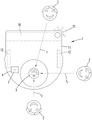
Fig. 1 shows a vehicle 1 which travels autonomously in an environment, which vehicle 1 is designed here as a suction robot. The vehicle 1 has a housing 11, on the upper side of which housing 11 a display 4 with a display area 7 is designed. Furthermore, the vehicle 1 has motor-driven wheels 12 (see fig. 2 to 4) for travelling in the environment and one or more cleaning elements 10 for performing cleaning work. The vehicle 1 also has a triangulation device, not shown in detail, which can measure distances in a detection plane over an angular range of 360 °, i.e. around the vehicle 1. The triangulation device has, for example, a laser for emitting a light beam. The light beam is emitted through an opening of the housing 11 of the vehicle 1 and scans the surroundings of the vehicle 1 over an angular range of 360 °. When the light beam encounters an obstacle, at least a portion is reflected and detected by the sensor of the triangulation device. The reflected portion touches another location of the sensor depending on the distance between the triangulation device and the obstacle that reflected the beam. Based on the position, the distance of the obstacle to the vehicle 1 can be determined. In addition to the triangulation device, the vehicle 1 also has a distance measuring device, not shown here, which is assigned to the wheels 12 of the vehicle 1 and can measure the distance covered and the direction of travel. The vehicle 1 has an internal memory and a computing device, by means of which an environment map of the surroundings of the vehicle 1 can be created from the measurement data. Based on this environment map, the vehicle 1 can orient and plan a travel path within the environment, for example, for suitability for floor cleaning in a home. To create an environment map, the measurement data acquired by the ranging device is compared with the environment data of the triangulation device. The created environment map may then be displayed to the user of the vehicle 1 on the display 4 of the vehicle 1 as desired.
In addition, the vehicle 1 has an image acquisition device 5, i.e. a camera, which image acquisition device 5 is rotatably arranged such that the detection range of the image acquisition device 5 can be rotated around the vehicle 1 within an angular range of 360 °. The image recording device 5 is connected in communication with a computing device of the vehicle 1, so that the captured image data can be evaluated by means of the computing device.
Fig. 2 shows an operation process of the vehicle 1 by the user 2. The vehicle 1 is connected here, for example, to a base station 13 in order to charge a battery. In the illustrated room situation, the user 2 is located in front of the vehicle 1 with respect to the normal main direction of travel of the vehicle 1, i.e. where the cleaning elements 10 of the vehicle 1 are advancing. The cleaning elements 10 are here, for example, motor-driven cleaning rollers and side brushes. The user 2 wants to make a selection from the information 3 displayed on the display 4. These pieces of information 3 can be, for example, different adjustable power levels of the motor-fan unit of the vehicle 1. These information 3 are displayed in the display direction rAIs shown on the display area 7 of the display 4. The display direction rASubstantially corresponding to the current gaze direction r of the user 2 at the vehicle 11. Gaze direction r of user 21May fall on different local areas of the vehicle 1, for example on the display 4, on a part of the housing 11 of the vehicle 1 or in the direction of the image acquisition device 5. In the embodiment shown it is assumed that the user 2 gazes in the direction of the image acquisition means 5 such that the direction of gaze r1Extending along a straight line between the eyes of the user 2 and the image acquisition means 5. At the same time, the user 2 guides his hand 6 in the direction of the display 4, thereby defining by the position and orientation of his hand 6Operating direction r4. Operating direction r4Which here corresponds to the direction of the index finger of the hand 6. From the display direction r as shown in fig. 2, in which the information 3 is displayedASubstantially parallel to the gaze direction r1And/or the operating direction r4Oriented, the user 2 may also operate the vehicle 1 from an offset spatial position and direction. This situation is shown in fig. 3.
Fig. 3 shows an arrangement of the vehicle 1 and the user 2, wherein the user is located behind the vehicle 1 with respect to the main direction of travel of the vehicle 1. In order to enable the user 2 to optimally read the information 3 from the display 4 at this time from this spatial position as well, in particular without moving relative to the vehicle 1, the following method steps are carried out from the situation shown in fig. 2.
First, the user 2 turns to the vehicle 1. At this point he looks at the vehicle 1, for example at an image capture device 5 arranged centrally on the vehicle 1 and guides his hand 6 in the direction of the display 4, on which display 4 he wants to make a selection from the displayed information 3. Gaze direction r2And an operating direction r5Here, the user 2 is directed to the vehicle 1 from a position behind the vehicle 1. During operation of the vehicle 1, the image capture device 5 captures images of the surroundings of the vehicle 1 at predetermined time intervals. The image acquisition device 5 transmits the captured image data to a computing device of the vehicle 1, where an analysis takes place, in particular with regard to the recognition of the presence of the user 2 within the immediate environment of the vehicle 1. The image processing takes place here, for example, by means of a face recognition method which on the one hand recognizes the face shown in the image and on the other hand can assign said face to the registered user 2 of the vehicle 1. For this purpose, the image data are compared with correspondingly stored reference data. The face recognition method further analyzes these data for whether the user 2 is currently looking at the vehicle 1 or another direction away from the vehicle 1. Here, the user 2 is looking in the direction r2Looking at the vehicle 1, this is understood as the operational desire of the user 2. Furthermore, the display 4, which is designed as a capacitive touch screen, detects the approach of the hand 6 of the user 2 to the display 4, whereby the operational desire of the user 2 is likewise inferred. According to the capacitance value of each section of the display 4, the meter of the vehicle 1The computing device recognizes the operating direction r5Said operating direction r5Which corresponds to the pointing direction of the index finger of the hand 6 of the user 2. Then, the gaze direction r2And an operating direction r5Are vectorially compared and combined to form a vector corresponding to the gaze direction r2And an operating direction r5The calculated average value of (c). The averaged direction is then assigned to the display direction r of the display 4BThe information 3 displayed on the display 4 is along said display direction rBOriented relative to the housing 11 of the vehicle 1. Starting from the situation shown in fig. 2, the information 3 is rotated by 180 ° according to the situation of fig. 3, so that the user 2 can read the information 3 in a conventional manner without having to move relative to the vehicle 1.
Fig. 4 schematically shows a vehicle 1 and different gaze directions r of one or more users 2 to the vehicle 11,r2,r3. First gaze direction r1This corresponds to the situation shown in fig. 2, in which the user 2 is looking at the vehicle 1 from the front. Gaze direction r2Corresponding to the presence of the user 2 behind the vehicle 1. The gazing direction r2Substantially corresponding to the situation shown in fig. 3. Furthermore, a gaze direction r is shown in which the user 2 gazes at the vehicle 1 from one side3. In addition to the gaze directions r1, r2, r3 shown, there may also be a large number of other gaze directions r1,r2,r3. The position of the user 2 around the vehicle 1 can be detected by the rotatability of the image capturing device 5 or by the image capturing device 5 equipped with an optical system (e.g., a wide-angle optical system or a fisheye optical system) that enlarges the capturing angle. In contrast, the display 4 has four predetermined display directions rA,rB,rCAlong said display direction, information 3 may be displayed. These display directions rA,rB,rCOriented parallel to the side edges of the display 4, so that the display area 7 of the display 4 can be optimally utilized.
Fig. 5 and 6 show two alternative embodiments of the display 4 of the vehicle 1, in which the information 3 can be displayed in any display direction r that can be selected steplesslyA,rB,rCAnd (6) displaying.
Fig. 5 shows an embodiment of the display 4, the display 4 having a circular display area 7. The display area 7 is designed to display the information 3 in each section. The display area 7 has a diameter D corresponding to the diagonal D of the local area in which the information 3 is displayed. The local area containing the information 3 is designed as a square, wherein the corners of the square move along the circumference of the circular display 4 when the information 3 is rotated on the display 4. The information 3 is always fully represented on the display area 7, regardless of the current orientation of the information 3 on the display 4.
Fig. 6 shows a display 4 which is designed as a square and has a display area 7, which display area 7 can be used to display information 3 over its entire longitudinal and transverse extent. In the center on the display area 7, a likewise square area is occupied by the displayed information 3, which information 3 can be rotated about the center of the display area 7 depending on the detected spatial position of the user 2. The display area 7 has a side length 8 which is the same as the diagonal D of the partial area of the display 4 occupied by the information 3. The local area occupied by the information 3 has a maximum side length 9. Since the information 3 likewise occupies a square area, all side lengths 9 are of equal size. When the orientation of the displayed information 3 changes, the corners of the square move on a circular track (shown in dashed lines). The circular track is incorporated in the display area 7 such that the outermost corner region of the displayed information 3 is always located within the display area 7 and therefore no information 3 is cut out when the orientation of the information 3 is changed.
Fig. 7 and 8 show different embodiments of the display 4, the information 3 displayed on the display 4 having different layouts.
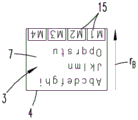
Fig. 7a, 7b and 7c each show a display 4, on which display 4 the information 3 is presented in text form on the one hand and the operating element 15 on the other hand. Operating elements 15 are presented on the display 4 in the form of a touch surface on which the user 2 can press in order to select a menu. The operating element 15 is arranged in the edge region of the display region 7 of the display 4, i.e. as a function of the display direction rA,rB,rCUnder the presented text, the user 2 is enabled to control the operationOne of the elements 15 does not obscure the other information 3 displayed on the display 4 with his hand 6. Fig. 7a, 7b and 7c show different display directions r of the information 3B、rC、rAWhich correspond to different positions of the user 2 relative to the vehicle 1. The display direction r of the information 3 shown in fig. 7aBCorresponding to the situation where the user 2 is located at the upper side in the image plane shown. Fig. 7b corresponds to the situation where the user 2 is located to the right of the display 4, and fig. 7c finally shows the situation where the user 2 views the vehicle 1 from the direction of the lower side. In all cases shown, the information 3 is arranged on the display 4 such that the operating element 15 always points in the direction of the user and is therefore always located between the other displayed information 3 (here the text portion) and the user 2.
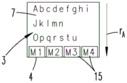
Fig. 8a, 8b and 8c show a further embodiment of a display 4, which display 4 is assigned a control element 14 of the pushbutton type separately outside the display area 7. The operating element 15 shown on the display 4 forms in this case an interpretation and/or labeling for the associated control element 14, so that the user 2 knows which functions the control element 14 has. In order to keep the operating element 15 always beside the associated control element 14 even when the orientation of the message 3 on the display 4 changes, the operating element 15 is always arranged at the upper edge of the display 4 in the image plane shown. However, the orientation of the label shown on the operating element 15 is changed such that it corresponds to the orientation of the further information 3, i.e. the respective display direction rB(FIG. 8a), rC(FIG. 8b) and rA(FIG. 8 c).
List of reference numerals
1 vehicle
2 users
3 information
4 display
5 image acquisition device
6 hand
7 display area
8 side length
9 side length
10 cleaning element
11 casing
12 wheels
13 base station
14 control element
15 operating element
rADisplaying direction
rBDisplaying direction
rCDisplaying direction
r1Gaze direction
r2Gaze direction
r3Gaze direction
r4Operating direction
r5Operating direction
d diameter
D diagonal line
Claims (14)
1. A method for operating an autonomously traveling, unmanned vehicle (1) within an environment, wherein the vehicle (1) detects obstacles and/or persons located within the surrounding environment, wherein information (3) is displayed to a user (2) on a display (4) of the vehicle (1), which display (4) is horizontally oriented with reference to a display plane while the vehicle (1) is running, characterized in that when the presence of a user (2) is detected, the spatial position of this user (2) relative to the vehicle (1) is detected, and the orientation of the displayed information (3) is changed depending on the measured spatial position of the user (2), wherein the information (3) can be rotated +/-180 DEG based on a previous orientation relative to the display (4) so that the user (2) can read the information (3) without moving relative to the vehicle (1), wherein the operating elements (15) displayed on the display (4) are recombined relative to one another as a function of the spatial position of the user (2), wherein the gaze direction of the user is determined by means of a facial recognition method and the operating direction in which the user operates the vehicle is detected, wherein the gaze direction and the operating direction are vectorially compared and combined to form a vector which corresponds to a calculated average of the gaze direction and the operating direction, and wherein the averaged direction is assigned to a display direction of the display in which the information displayed on the display is oriented relative to the housing of the vehicle.
2. Method according to claim 1, characterized in that the presence of the user (2) is detected by means of an image acquisition device (5).
3. Method according to claim 1 or 2, characterized in that the gaze direction (r) of the user (2) is determined by means of a facial recognition method1,r2,r3)。
4. Method according to claim 1, characterized in that the operating direction (r) in which the vehicle (1) is operated by a user (2) is detected4,r5)。
5. The method according to claim 4, characterized by detecting the orientation of a hand (6) used by a user (2) on the vehicle (1).
6. Method according to claim 5, characterized in that the orientation of the hand (6) is detected by means of a capacitive sensor and/or by means of an image acquisition device (5).
7. Method according to claim 1, characterized in that, depending on the measured spatial position of the user (2), a plurality of possible display directions (r) from the display (4) are derivedA,rB,rC) One of them is selected.
8. Method according to claim 1, characterized in that the plurality of sections of the information (3) displayed on the display (4) are recombined with respect to each other according to the spatial position of the user (2).
9. Method according to claim 1, characterized by the following successive method steps:
-capturing the surroundings of the vehicle (1) by means of an image capture device (5),
-identifying the presence of a user (2) in the surroundings of the vehicle (1),
-determining a gaze direction (r) of a user (2)1) And/or the operating direction (r) of the hand (6)2),
-associating the determined gaze direction (r1) and/or the operation direction (r2) with a display direction (r2) of the display (4)A,rB,rC) The information of the user is associated with the user,
-with an associated display direction (r)A,rB,rC) To display information.
10. Method according to claim 1, characterized in that the vehicle (1) is a cleaning robot.
11. The method according to claim 6, characterized in that the capacitive sensor is a capacitive display (4).
12. An autonomous, driverless vehicle (1) within an environment, the vehicle (1) having an image acquisition device (5) for detecting obstacles and/or persons located within the surrounding environment, wherein the vehicle (1) has a display (4) for displaying information (3), the display (4) being generally horizontally oriented with reference to a display plane when the vehicle (1) is in operation, and the vehicle (1) has a computing device which is arranged, when the presence of a user (2) is detected, to detect the spatial position of the user (2) relative to the vehicle (1) and to change the display direction (r) of the information displayed on the display (4) in dependence on the detected spatial position of the user (2)A,rB,rC) Wherein the information (3) can be rotated +/-180 DEG on the basis of a previous orientation relative to the display (4) in order that the user (2) can read the information (3) without moving relative to the vehicle (1), wherein the operating elements (15) displayed on the display (4) are recombined relative to one another as a function of the spatial position of the user (2), wherein the gaze direction of the user is determined by means of a facial recognition method, and the operating direction in which the user operates the vehicle is detected, wherein the gaze direction and the operating direction are vectorially determinedThe comparison and combination is carried out to form a vector which corresponds to the calculated mean value of the gaze direction and the operating direction, and the mean direction is associated with a display direction of a display in which the information displayed on the display is oriented relative to the housing of the vehicle.
13. Vehicle according to claim 12, characterized in that the display (4) has a display area (7) with a side length (8) at least equal to the largest possible diagonal (D) of the information (3) displayed on the display (4) and/or the display (4) has a circular display area (7) with a diameter (D) at least equal to the diagonal (D) of the information (3) displayed on the display (4).
14. Vehicle according to claim 12 or 13, characterized in that the vehicle (1) is a cleaning robot.
Applications Claiming Priority (2)
| Application Number | Priority Date | Filing Date | Title |
|---|---|---|---|
| DE102017108194.1A DE102017108194A1 (en) | 2017-04-18 | 2017-04-18 | Method for operating a self-propelled vehicle |
| DE102017108194.1 | 2017-04-18 |
Publications (2)
| Publication Number | Publication Date |
|---|---|
| CN108720731A CN108720731A (en) | 2018-11-02 |
| CN108720731B true CN108720731B (en) | 2022-01-25 |
Family
ID=61952532
Family Applications (1)
| Application Number | Title | Priority Date | Filing Date |
|---|---|---|---|
| CN201810336966.0A Active CN108720731B (en) | 2017-04-18 | 2018-04-16 | Method for operating an autonomously traveling vehicle |
Country Status (7)
| Country | Link |
|---|---|
| US (1) | US10895880B2 (en) |
| EP (1) | EP3392738B1 (en) |
| JP (1) | JP2018181338A (en) |
| CN (1) | CN108720731B (en) |
| DE (1) | DE102017108194A1 (en) |
| ES (1) | ES2894289T3 (en) |
| TW (1) | TW201841586A (en) |
Families Citing this family (6)
| Publication number | Priority date | Publication date | Assignee | Title |
|---|---|---|---|---|
| DE102017108194A1 (en) * | 2017-04-18 | 2018-10-18 | Vorwerk & Co. Interholding Gmbh | Method for operating a self-propelled vehicle |
| BR112021007260A2 (en) | 2018-10-19 | 2021-08-10 | Bissell Inc. | surface cleaning device |
| USD938115S1 (en) | 2018-11-30 | 2021-12-07 | Irobot Corporation | Autonomous floor cleaning robot |
| CN112596602A (en) * | 2019-09-17 | 2021-04-02 | 奥迪股份公司 | Apparatus for adjusting display of information on display screen and corresponding method and medium |
| DE102020128096A1 (en) | 2020-10-26 | 2022-04-28 | Vorwerk & Co. Interholding Gesellschaft mit beschränkter Haftung | Mobile household device with a display |
| CN114557649B (en) * | 2022-01-28 | 2023-04-14 | 北京顺造科技有限公司 | Cleaning device and cleaning device user interface display method |
Citations (5)
| Publication number | Priority date | Publication date | Assignee | Title |
|---|---|---|---|---|
| WO2001072199A1 (en) * | 2000-03-28 | 2001-10-04 | It-Clean I Åstorp Ab | Method and device for cleaning |
| CN1575730A (en) * | 2003-07-29 | 2005-02-09 | 乐金电子(天津)电器有限公司 | Safety device for vacuum dust cleaner |
| EP2502540A2 (en) * | 2009-11-16 | 2012-09-26 | LG Electronics Inc. | Robot cleaner and method for controlling same |
| CN103845003A (en) * | 2012-12-05 | 2014-06-11 | Lg电子株式会社 | Robot cleaner |
| CN104737085A (en) * | 2012-09-24 | 2015-06-24 | 罗巴特公司 | Robot and method for autonomous inspection or processing of floor areas |
Family Cites Families (33)
| Publication number | Priority date | Publication date | Assignee | Title |
|---|---|---|---|---|
| US6243076B1 (en) * | 1998-09-01 | 2001-06-05 | Synthetic Environments, Inc. | System and method for controlling host system interface with point-of-interest data |
| US7306337B2 (en) * | 2003-03-06 | 2007-12-11 | Rensselaer Polytechnic Institute | Calibration-free gaze tracking under natural head movement |
| JP2005100084A (en) * | 2003-09-25 | 2005-04-14 | Toshiba Corp | Image processor and method |
| JP3926837B2 (en) * | 2004-06-04 | 2007-06-06 | 松下電器産業株式会社 | Display control method and apparatus, program, and portable device |
| JP4528295B2 (en) * | 2006-12-18 | 2010-08-18 | 株式会社日立製作所 | GUIDANCE ROBOT DEVICE AND GUIDANCE SYSTEM |
| US8152071B2 (en) * | 2008-02-08 | 2012-04-10 | Motion Computing, Inc. | Multi-purpose portable computer with integrated devices |
| DE102008014912B4 (en) | 2008-03-19 | 2023-01-19 | Vorwerk & Co. Interholding Gmbh | Automatically movable floor dust collector |
| CN102046059A (en) * | 2008-08-08 | 2011-05-04 | 松下电器产业株式会社 | Control device and control method for cleaner, cleaner, control program for cleaner, and integrated electronic circuit |
| JP2010117260A (en) * | 2008-11-13 | 2010-05-27 | Epson Toyocom Corp | Correction parameter preparation method of attitude detector, device for correction parameter preparation of attitude detector, and attitude detector |
| KR101641237B1 (en) * | 2009-11-20 | 2016-07-21 | 엘지전자 주식회사 | Robot cleaner and controlling method of the same |
| JP2011192030A (en) * | 2010-03-15 | 2011-09-29 | Nippon Telegr & Teleph Corp <Ntt> | Information display device |
| JP2011240468A (en) * | 2010-05-21 | 2011-12-01 | Toyota Motor Corp | Contact type discriminating system for robot |
| US8757490B2 (en) * | 2010-06-11 | 2014-06-24 | Josef Bigun | Method and apparatus for encoding and reading optical machine-readable data codes |
| DE102011000250A1 (en) | 2011-01-21 | 2012-07-26 | Vorwerk & Co. Interholding Gmbh | Method for determining the position of a self-moving device |
| US8885882B1 (en) * | 2011-07-14 | 2014-11-11 | The Research Foundation For The State University Of New York | Real time eye tracking for human computer interaction |
| US20130038437A1 (en) * | 2011-08-08 | 2013-02-14 | Panasonic Corporation | System for task and notification handling in a connected car |
| US8726457B2 (en) * | 2011-12-30 | 2014-05-20 | Techtronic Floor Care Technology Limited | Vacuum cleaner with display |
| US9123142B2 (en) * | 2012-10-02 | 2015-09-01 | At&T Intellectual Property I, L.P. | Adjusting content display orientation on a screen based on user orientation |
| US9398287B2 (en) * | 2013-02-28 | 2016-07-19 | Google Technology Holdings LLC | Context-based depth sensor control |
| US9766709B2 (en) * | 2013-03-15 | 2017-09-19 | Leap Motion, Inc. | Dynamic user interactions for display control |
| US10146299B2 (en) * | 2013-11-08 | 2018-12-04 | Qualcomm Technologies, Inc. | Face tracking for additional modalities in spatial interaction |
| US9659403B1 (en) * | 2014-01-06 | 2017-05-23 | Leap Motion, Inc. | Initializing orientation in space for predictive information for free space gesture control and communication |
| US10209779B2 (en) * | 2014-02-21 | 2019-02-19 | Samsung Electronics Co., Ltd. | Method for displaying content and electronic device therefor |
| KR102072387B1 (en) * | 2014-03-20 | 2020-02-03 | 삼성전자주식회사 | Robot cleaner and method for controlling the same |
| WO2015188011A1 (en) * | 2014-06-04 | 2015-12-10 | Quantum Interface, Llc. | Dynamic environment for object and attribute display and interaction |
| JP6826804B2 (en) * | 2014-08-29 | 2021-02-10 | 東芝ライフスタイル株式会社 | Autonomous vehicle |
| US10317992B2 (en) * | 2014-09-25 | 2019-06-11 | Microsoft Technology Licensing, Llc | Eye gaze for spoken language understanding in multi-modal conversational interactions |
| JP2016087106A (en) * | 2014-11-05 | 2016-05-23 | シャープ株式会社 | Cleaning support device and cleaner |
| US10817172B2 (en) * | 2015-03-27 | 2020-10-27 | Intel Corporation | Technologies for graphical user interface manipulations using multi-finger touch interactions |
| WO2016174784A1 (en) * | 2015-04-28 | 2016-11-03 | シャープ株式会社 | Control device and display device |
| KR102427836B1 (en) * | 2015-06-26 | 2022-08-02 | 삼성전자주식회사 | Cleaning robot, information providing system and method for providing information |
| DE102017108194A1 (en) * | 2017-04-18 | 2018-10-18 | Vorwerk & Co. Interholding Gmbh | Method for operating a self-propelled vehicle |
| WO2019182378A1 (en) * | 2018-03-21 | 2019-09-26 | Lg Electronics Inc. | Artificial intelligence server |
-
2017
- 2017-04-18 DE DE102017108194.1A patent/DE102017108194A1/en not_active Withdrawn
-
2018
- 2018-03-29 EP EP18164993.0A patent/EP3392738B1/en active Active
- 2018-03-29 ES ES18164993T patent/ES2894289T3/en active Active
- 2018-04-10 JP JP2018075191A patent/JP2018181338A/en active Pending
- 2018-04-16 CN CN201810336966.0A patent/CN108720731B/en active Active
- 2018-04-17 US US15/954,986 patent/US10895880B2/en active Active
- 2018-04-17 TW TW107113059A patent/TW201841586A/en unknown
Patent Citations (5)
| Publication number | Priority date | Publication date | Assignee | Title |
|---|---|---|---|---|
| WO2001072199A1 (en) * | 2000-03-28 | 2001-10-04 | It-Clean I Åstorp Ab | Method and device for cleaning |
| CN1575730A (en) * | 2003-07-29 | 2005-02-09 | 乐金电子(天津)电器有限公司 | Safety device for vacuum dust cleaner |
| EP2502540A2 (en) * | 2009-11-16 | 2012-09-26 | LG Electronics Inc. | Robot cleaner and method for controlling same |
| CN104737085A (en) * | 2012-09-24 | 2015-06-24 | 罗巴特公司 | Robot and method for autonomous inspection or processing of floor areas |
| CN103845003A (en) * | 2012-12-05 | 2014-06-11 | Lg电子株式会社 | Robot cleaner |
Also Published As
| Publication number | Publication date |
|---|---|
| ES2894289T3 (en) | 2022-02-14 |
| US20180299902A1 (en) | 2018-10-18 |
| EP3392738A1 (en) | 2018-10-24 |
| EP3392738B1 (en) | 2021-08-18 |
| DE102017108194A1 (en) | 2018-10-18 |
| TW201841586A (en) | 2018-12-01 |
| CN108720731A (en) | 2018-11-02 |
| JP2018181338A (en) | 2018-11-15 |
| US10895880B2 (en) | 2021-01-19 |
Similar Documents
| Publication | Publication Date | Title |
|---|---|---|
| CN108720731B (en) | Method for operating an autonomously traveling vehicle | |
| EP3027101B1 (en) | Auto-cleaning system, cleaning robot and method of controlling the cleaning robot | |
| US11468983B2 (en) | Time-dependent navigation of telepresence robots | |
| US20220199253A1 (en) | Interfacing With a Mobile Telepresence Robot | |
| US10542859B2 (en) | Cleaning robot and controlling method thereof | |
| US11886186B2 (en) | Mobile robot and control method of mobile robot | |
| US10967512B2 (en) | Moving robot and controlling method | |
| EP3585571B1 (en) | Moving robot and control method thereof | |
| US10423163B2 (en) | Mobile robot and method of controlling same | |
| US10291765B2 (en) | Mobile device, robot cleaner, and method for controlling the same | |
| US9950429B2 (en) | Robot cleaning system and method of controlling robot cleaner | |
| WO2019144541A1 (en) | Cleaning robot | |
| KR102314637B1 (en) | Robot cleaner, and robot cleaning system | |
| JP5963372B2 (en) | How to make a mobile robot follow people | |
| KR101566207B1 (en) | Robot cleaner and control method thereof | |
| US20050212680A1 (en) | Self-propelled cleaner | |
| CN110419211A (en) | Information processing unit, information processing method and message handling program | |
| CN111493751A (en) | Cleaning robot and control method thereof | |
| JP2015092348A (en) | Mobile human interface robot | |
| KR20180074141A (en) | Moving robot | |
| KR102314537B1 (en) | Moving Robot and controlling method | |
| KR20210015126A (en) | Moving Robot | |
| CN114905503A (en) | Robot control system, robot control method, and storage medium |
Legal Events
| Date | Code | Title | Description |
|---|---|---|---|
| PB01 | Publication | ||
| PB01 | Publication | ||
| SE01 | Entry into force of request for substantive examination | ||
| SE01 | Entry into force of request for substantive examination | ||
| GR01 | Patent grant | ||
| GR01 | Patent grant |