CN108702573B - Flat panel speaker and display device - Google Patents
Flat panel speaker and display device Download PDFInfo
- Publication number
- CN108702573B CN108702573B CN201780012260.2A CN201780012260A CN108702573B CN 108702573 B CN108702573 B CN 108702573B CN 201780012260 A CN201780012260 A CN 201780012260A CN 108702573 B CN108702573 B CN 108702573B
- Authority
- CN
- China
- Prior art keywords
- vibration
- display unit
- control member
- flat panel
- vibrator
- Prior art date
- Legal status (The legal status is an assumption and is not a legal conclusion. Google has not performed a legal analysis and makes no representation as to the accuracy of the status listed.)
- Active
Links
Images


Classifications
-
- H—ELECTRICITY
- H04—ELECTRIC COMMUNICATION TECHNIQUE
- H04R—LOUDSPEAKERS, MICROPHONES, GRAMOPHONE PICK-UPS OR LIKE ACOUSTIC ELECTROMECHANICAL TRANSDUCERS; DEAF-AID SETS; PUBLIC ADDRESS SYSTEMS
- H04R1/00—Details of transducers, loudspeakers or microphones
- H04R1/02—Casings; Cabinets ; Supports therefor; Mountings therein
- H04R1/025—Arrangements for fixing loudspeaker transducers, e.g. in a box, furniture
-
- H—ELECTRICITY
- H04—ELECTRIC COMMUNICATION TECHNIQUE
- H04R—LOUDSPEAKERS, MICROPHONES, GRAMOPHONE PICK-UPS OR LIKE ACOUSTIC ELECTROMECHANICAL TRANSDUCERS; DEAF-AID SETS; PUBLIC ADDRESS SYSTEMS
- H04R7/00—Diaphragms for electromechanical transducers; Cones
- H04R7/26—Damping by means acting directly on free portion of diaphragm or cone
-
- H—ELECTRICITY
- H04—ELECTRIC COMMUNICATION TECHNIQUE
- H04R—LOUDSPEAKERS, MICROPHONES, GRAMOPHONE PICK-UPS OR LIKE ACOUSTIC ELECTROMECHANICAL TRANSDUCERS; DEAF-AID SETS; PUBLIC ADDRESS SYSTEMS
- H04R7/00—Diaphragms for electromechanical transducers; Cones
- H04R7/02—Diaphragms for electromechanical transducers; Cones characterised by the construction
- H04R7/04—Plane diaphragms
-
- H—ELECTRICITY
- H04—ELECTRIC COMMUNICATION TECHNIQUE
- H04R—LOUDSPEAKERS, MICROPHONES, GRAMOPHONE PICK-UPS OR LIKE ACOUSTIC ELECTROMECHANICAL TRANSDUCERS; DEAF-AID SETS; PUBLIC ADDRESS SYSTEMS
- H04R9/00—Transducers of moving-coil, moving-strip, or moving-wire type
- H04R9/02—Details
- H04R9/025—Magnetic circuit
-
- G—PHYSICS
- G02—OPTICS
- G02F—OPTICAL DEVICES OR ARRANGEMENTS FOR THE CONTROL OF LIGHT BY MODIFICATION OF THE OPTICAL PROPERTIES OF THE MEDIA OF THE ELEMENTS INVOLVED THEREIN; NON-LINEAR OPTICS; FREQUENCY-CHANGING OF LIGHT; OPTICAL LOGIC ELEMENTS; OPTICAL ANALOGUE/DIGITAL CONVERTERS
- G02F1/00—Devices or arrangements for the control of the intensity, colour, phase, polarisation or direction of light arriving from an independent light source, e.g. switching, gating or modulating; Non-linear optics
- G02F1/01—Devices or arrangements for the control of the intensity, colour, phase, polarisation or direction of light arriving from an independent light source, e.g. switching, gating or modulating; Non-linear optics for the control of the intensity, phase, polarisation or colour
- G02F1/13—Devices or arrangements for the control of the intensity, colour, phase, polarisation or direction of light arriving from an independent light source, e.g. switching, gating or modulating; Non-linear optics for the control of the intensity, phase, polarisation or colour based on liquid crystals, e.g. single liquid crystal display cells
- G02F1/133—Constructional arrangements; Operation of liquid crystal cells; Circuit arrangements
- G02F1/1333—Constructional arrangements; Manufacturing methods
- G02F1/133394—Piezoelectric elements associated with the cells
-
- H—ELECTRICITY
- H04—ELECTRIC COMMUNICATION TECHNIQUE
- H04R—LOUDSPEAKERS, MICROPHONES, GRAMOPHONE PICK-UPS OR LIKE ACOUSTIC ELECTROMECHANICAL TRANSDUCERS; DEAF-AID SETS; PUBLIC ADDRESS SYSTEMS
- H04R2440/00—Bending wave transducers covered by H04R, not provided for in its groups
- H04R2440/05—Aspects relating to the positioning and way or means of mounting of exciters to resonant bending wave panels
-
- H—ELECTRICITY
- H04—ELECTRIC COMMUNICATION TECHNIQUE
- H04R—LOUDSPEAKERS, MICROPHONES, GRAMOPHONE PICK-UPS OR LIKE ACOUSTIC ELECTROMECHANICAL TRANSDUCERS; DEAF-AID SETS; PUBLIC ADDRESS SYSTEMS
- H04R2499/00—Aspects covered by H04R or H04S not otherwise provided for in their subgroups
- H04R2499/10—General applications
- H04R2499/15—Transducers incorporated in visual displaying devices, e.g. televisions, computer displays, laptops
-
- H—ELECTRICITY
- H04—ELECTRIC COMMUNICATION TECHNIQUE
- H04R—LOUDSPEAKERS, MICROPHONES, GRAMOPHONE PICK-UPS OR LIKE ACOUSTIC ELECTROMECHANICAL TRANSDUCERS; DEAF-AID SETS; PUBLIC ADDRESS SYSTEMS
- H04R7/00—Diaphragms for electromechanical transducers; Cones
- H04R7/02—Diaphragms for electromechanical transducers; Cones characterised by the construction
- H04R7/04—Plane diaphragms
- H04R7/045—Plane diaphragms using the distributed mode principle, i.e. whereby the acoustic radiation is emanated from uniformly distributed free bending wave vibration induced in a stiff panel and not from pistonic motion
Abstract
A flat panel speaker according to one embodiment of the present disclosure includes a flat panel and a plurality of vibrators disposed on a rear surface of the flat panel. The plurality of vibrators are disposed so as to avoid a position which is most likely to vibrate in the entire audio frequency range when the plurality of vibrators generate vibrations in the flat panel. As a result, a large standing wave is not easily generated at the flat plate.
Description
Technical Field
The present disclosure relates to a flat panel speaker and a display device.
Background
The thickness and weight of displays have been rapidly reduced. Therefore, the thickness and weight of the speaker have also been reduced, and it has been proposed to use a Flat Panel Speaker (FPS) instead of or together with the cone speaker. A series of uses of the flat panel speaker are expected to increase, and the flat panel speaker can be applied not only to a display but also to a billboard (post) for exhibition and the like. For example, patent documents 1 to 3 each disclose a flat panel speaker.
CITATION LIST
Patent document
Patent document 1: japanese unexamined patent application publication No. 2007-143010
Patent document 2: japanese unexamined patent application publication No. 2009-
Patent document 3: japanese unexamined patent application publication No. (Japanese translation of published PCT application) 2002-510182
Disclosure of Invention
However, in a typical flat panel speaker, there are cases where sound quality deteriorates due to the influence of standing waves generated in the vibration plate, for example, cases where flare (glare) occurs in sound and cases where sound of a specific frequency band is not easily emitted. Therefore, it is desirable to provide a flat panel speaker and a display device so that sound quality deterioration can be suppressed.
A first flat panel speaker according to an embodiment of the present disclosure includes: a flat plate; and a plurality of vibrators disposed on a rear surface of the flat plate and vibrating the flat plate. The plurality of vibrators are disposed so as to avoid a position where the plurality of vibrators most easily vibrate in the entire audio frequency range when generating vibrations in the flat panel.
The first display device according to an embodiment of the present disclosure includes: a display unit having a sheet-like shape and displaying an image; and a plurality of vibrators disposed on a rear surface of the display unit and vibrating the display unit. The plurality of vibrators are disposed so as to avoid a position where the plurality of vibrators most easily vibrate in the entire audio frequency range when generating vibrations in the display unit.
In the first flat speaker and the first display device according to the respective embodiments of the present invention, the plurality of vibrators disposed on the rear surface of the flat panel or the display unit are disposed so as to avoid a position where the plurality of vibrators most easily vibrate in the entire audio frequency range when generating vibrations in the flat panel or the display unit. Therefore, a large standing wave is not easily generated to the flat panel or the display unit.
A second flat panel speaker according to an embodiment of the present disclosure includes: a flat plate; and a vibrator disposed on a rear surface of the flat plate and vibrating the flat plate. The vibrator is disposed so as to avoid a position most likely to vibrate in the entire audio frequency range when vibration is generated in the flat panel by the vibrator.
The second display device according to an embodiment of the present disclosure includes: a display unit having a sheet-like shape and displaying an image; and a vibrator disposed on a rear surface of the display unit and vibrating the display unit. The vibrator is provided so as to avoid a position most likely to vibrate in the entire audio frequency range when vibration is generated in the display unit by the vibrator.
In the second flat speaker and the second display device according to the respective embodiments of the present invention, the plurality of vibrators disposed on the rear surface of the flat panel or the display unit are disposed so as to avoid a position where the plurality of vibrators most easily vibrate in the entire audio frequency range when generating vibrations in the flat panel or the display unit. Therefore, a large standing wave is not easily generated to the flat panel or the display unit.
Effects of the invention
According to the first flat speaker and the first display device of the respective embodiments of the present invention, a large standing wave is not easily generated with respect to the flat panel or the display unit, so that a sound quality degradation can be suppressed.
According to the second flat speaker and the second display device of the respective embodiments of the present invention, a large standing wave is not easily generated with respect to the flat panel or the display unit, so that a sound quality degradation can be suppressed.
It should be noted that the effects of this technique are not necessarily limited to the effects described herein, and may be any of the effects described herein.
Drawings
Fig. 1 shows a side configuration example of a flat panel speaker according to a first embodiment of the present disclosure.
Fig. 2 shows a rear surface configuration example of the flat panel speaker in fig. 1.
Fig. 3 shows a configuration example of the back surface of the flat panel speaker when the rear bottom case in fig. 2 is removed.
FIG. 4 shows a cross-sectional configuration example taken along line A-A in FIG. 3.
FIG. 5 shows a cross-sectional configuration example taken along the line B-B in FIG. 3.
Fig. 6 shows a cross-sectional configuration example of the vibration control member in fig. 4.
Fig. 7 shows a planar configuration example of the vibration control member in fig. 4.
Fig. 8 shows a planar configuration example of the vibration control member in fig. 4.
Fig. 9 shows a planar configuration example of the vibration control member in fig. 4.
Fig. 10 shows a planar configuration example of the vibration control member in fig. 4.
Fig. 11 shows a planar configuration example of the vibration control member in fig. 4.
Fig. 12 shows a planar configuration example of the vibration control member in fig. 4.
Fig. 13 shows a planar configuration example of the vibration control member in fig. 4.
Fig. 14 shows a planar configuration example of the vibration control member in fig. 4.
Fig. 15 shows a planar configuration example of the vibration control member in fig. 4.
Fig. 16 shows a planar configuration example of the vibration control member in fig. 4.
Fig. 17 shows a planar configuration example of the vibration control member in fig. 4.
Fig. 18 shows a planar configuration example of the vibration control member in fig. 4.
Fig. 19 shows a planar configuration example of the vibration control member in fig. 4.
Fig. 20 shows a planar configuration example of the vibration control member in fig. 4.
Fig. 21 shows a modification of the cross-sectional configuration in fig. 5.
Fig. 22 shows a modification of the side structure of the flat panel speaker in fig. 1.
Fig. 23 shows a rear surface configuration example of the flat panel speaker in fig. 22.
Fig. 24 shows a side configuration example of a flat panel speaker according to a second embodiment of the present disclosure.
Fig. 25 shows a rear surface configuration example of the flat panel speaker in fig. 24.
Fig. 26 shows a configuration example of the back surface of the flat panel speaker when the rear chassis in fig. 25 is removed.
FIG. 27 shows a cross-sectional configuration example taken along the line A-A in FIG. 26.
Fig. 28 shows a modification of the cross-sectional structure in fig. 5.
Fig. 29 shows a modification of the cross-sectional configuration in fig. 21.
Fig. 30 shows a modification of the cross-sectional structure in fig. 27.
Fig. 31 shows a modification of the back surface structure in fig. 3.
Fig. 32 shows a modification of the back surface structure in fig. 27.
Fig. 33 shows a modification of the back surface structure in fig. 7.
Fig. 34 shows a modification of the back surface structure in fig. 31.
Fig. 35 shows a modification of the back surface structure in fig. 32.
Fig. 36 shows a modification of the back surface structure in fig. 33.
Fig. 37 shows a modification of the back surface structure in fig. 36.
Fig. 38 shows a modification of the back surface structure in fig. 36.
Fig. 39 shows a modification of the back surface structure in fig. 36.
Fig. 40 shows a modification of the back surface structure in fig. 36.
Fig. 41 shows a modification of the back surface structure in fig. 36.
Fig. 42 shows a modification of the back surface structure in fig. 36.
Fig. 43 shows a modification of the back surface structure in fig. 36.
Detailed Description
Some embodiments of the present disclosure are described in detail below with reference to the accompanying drawings. The following description is a specific example of the present disclosure, and the present disclosure is not limited to the following implementation.
<1, first embodiment >
[ Structure ]
A flat panel speaker 1 according to a first embodiment of the present disclosure is described. Fig. 1 shows a side configuration example of a flat panel speaker 1 according to the present embodiment. Fig. 2 shows an example of the rear surface configuration of the flat panel speaker 1 in fig. 1. The flat panel speaker 1 also functions as a display device for displaying an image. In other words, it can be said that the display device includes the built-in flat panel speaker 1 and is configured to be able to output sound from a display surface on which an image is displayed.
The flat panel speaker 1 includes a panel portion 10 serving as a vibration plate, for example, and a vibration portion 20 provided on a rear surface of the panel portion 10 and causing the panel portion 10 to vibrate. The flat panel speaker 1 further includes, for example, a signal processor 30 that controls the vibrating portion 20 and a support portion 40 that supports the panel portion 10 by the rotating portion 50. The rotation part 50 adjusts the tilt of the panel part 10 when the support part 40 supports the rear surface of the panel part 10. The rotation portion 50 is configured by, for example, a hinge that rotatably supports the panel portion 10 and the support portion 40.
The vibration part 20 and the signal processor 30 are disposed on the rear surface of the panel part 10. The panel portion 10 includes a rear bottom case 19 located on a rear surface side of the panel portion 10, and the rear bottom case 19 protects the panel portion 10, the vibrating portion 20, and the signal processor 30. The rear bottom case 19 is configured of, for example, a planar metal plate or a resin plate. The rear bottom case 19 is coupled to the rotation part 50.
Fig. 3 shows a configuration example of the back surface of the flat panel speaker 1 when the rear bottom case 19 is removed. Fig. 4 shows a cross-sectional configuration example taken along line a-a in fig. 3. Fig. 5 shows a cross-sectional configuration example taken along line B-B in fig. 3. It should be noted that fig. 5 shows an example of a cross-sectional configuration in the vicinity of the vibrator 21 (actuator) described later, but it is assumed that the cross-sectional configuration has a cross-sectional configuration similar to that in the vicinity of another vibrator (for example, the vibrator 22 (actuator)).
The panel portion 10 includes, for example: a display unit 11 having a thin plate-like shape to display an image; and an inner panel 12 (facing panel) disposed to face the display unit 11 with a gap 15 formed therebetween. In the display unit 11 serving as the vibration plate, for example, the edge of the display unit 11 may be rounded, and for example, four corners of the display unit 11 may be rounded. The panel portion 10 further includes, for example: a glass substrate 13 provided in contact with the rear surface of the inner panel 12; and a fixing member 14 disposed between the display unit 11 and the inner panel 12.
The fixing member 14 serves to fix the display unit 11 and the inner panel 12 to each other, and serves as a spacer that maintains the gap 15. The fixing member 14 is provided, for example, along an outer edge of the display unit 11. The fixing member 14 may have, for example, a degree of flexibility that allows the end edge of the display unit 11 to function as a free end when the display unit 11 vibrates. The fixing member 14 is configured of a cushioning layer such as sponge having an adhesive layer on each of both surfaces.
The inner plate 12 is a substrate that supports vibrators 21 and 22 described later. The inner panel 12 has, for example: an opening at a position where each of the vibrators 21 and 22 is to be mounted; and a convex portion 12A provided around the opening to support a fixing portion 23 described later. The convex portion 12A protrudes to the side opposite to the display unit 11. The glass substrate 13 has higher rigidity than the inner plate 12, and has an effect of suppressing flexure or vibration of the inner plate 12. The glass substrate 13 has an opening at a position facing the convex portion 12A. The opening provided in the glass substrate 13 has a size that allows the convex portion 12A and the vibrator 21 or the vibrator 22 to be inserted therein. Instead of the glass substrate 13, a resin substrate having a rigidity comparable to that of the glass substrate 13 may be provided.
The vibrating portion 20 includes, for example, two vibrators (vibrators 21 and 22). The vibrator 21 and the vibrator 22 have a common configuration. The vibrators 21 and 22 are arranged to avoid a position most likely to vibrate within the entire audio frequency range (for example, 20Hz to 20kHz) when vibration is generated in the display unit 11 by the vibrators 21 and 22. Examples of the "position most likely to vibrate" include a position of an antinode of a maximum standing wave that appears in the display unit 11 when vibration is generated in the display unit 11 by the vibrators 21 and 22. Further, the vibrators 21 and 22 are arranged so as to avoid a position where vibration is least likely to be generated in the display unit 11 through the vibrators 21 and 22 over the entire audio frequency range. The vibration of the display unit 11 is determined by measuring the vibration of the entire surface of the display unit 11 over the entire audio frequency range, for example, using a laser doppler vibrometer. The vibrators 21 and 22 are disposed, for example, at positions having an inseparable ratio in the lateral and vertical directions of the display unit 11. Examples of "non-divisible ratios" include 3:4, 5:7, 3:7, 2:5, and 7: 11.
The vibrator 21 is disposed on the left side when the display unit 11 is viewed from the rear surface. The vibrator 22 is disposed on the right side when the display unit 11 is viewed from the rear surface. The vibrators 21 and 22 each include, for example, a voice coil, a bobbin (bobbin) on which the voice coil is wound, and a magnetic circuit, and the vibrators 21 and 22 each function as a speaker actuator as a vibration source. When a sound current of an electric signal flows to the voice coil, the vibrators 21 and 22 each generate a driving force in the voice coil according to the principle of electromagnetic action. The driving force is transmitted to the display unit 11 through a vibration transmission member 24 described later, so that vibration is generated according to a change in acoustic current in the display unit 11. This causes the air to vibrate, thereby changing the sound pressure.
The vibrating portion 20 further includes, for example, a fixing portion 23 and a vibration transmission member 24 for each vibrator (the vibrators 21 and 22).
The fixing portion 23 has, for example, an opening 23a, and the opening 23a is provided to fix the vibrator 21 or the vibrator 22 in a state where the vibrator 21 or the vibrator 22 is inserted therein. The fixing portion 23 also has, for example, a plurality of screw holes 23b through each of which a screw is inserted 23b, and the screw is used to fix the fixing portion 23 to the boss portion 12A. For example, the vibrators (the vibrators 21 and 22) are each fixed to the inner plate 12 by a fixing portion 23. In addition to fixing the vibrator 21 or the vibrator 22 to the inner plate 12, the fixing portion 23 may also have a function, for example, as a heat sink that radiates heat generated from the vibrator 21 or the vibrator 22.
The vibration transmission member 24 is, for example, in contact with the rear surface of the display unit 11 and the skeleton of the vibrator 21 or 22 of the display unit 11, and is fixed to the rear surface of the display unit 11 and the skeleton of the vibrator 21 or 22. The vibration transmission member 24 is configured by a member having at least resiliency in a sound wave region (20Hz or more). The vibration transmission member 24 is configured of, for example, a thermosetting resin, a double-sided tape, or low-resilience urethane. In the case where the vibration transmission member 24 is configured of a thermosetting resin, for example, by passing a current into the voice coil, generating heat in the voice coil, and curing the thermosetting resin with the heat, the vibration transmission member 24 is formed. In the case where the vibration transmission member 24 is configured by a double-sided adhesive tape, for example, by inputting a constant pulse signal to the voice coil and firmly pressing the double-sided adhesive tape with the voice coil, the vibration transmission member 24 is fixed to the rear surface of the display unit 11 and to the vibrator 21 or the bobbin of the vibrator 22. In the case where the vibration transmission member 24 is configured of low resilience urethane, the low resilience urethane preferably has resilience characteristics in the sound wave region (20Hz or more), and has follow-up characteristics in the low frequency region (less than 20 Hz). Therefore, the low-resilience urethane can follow the displacement of the display unit 11 caused by the external impact without attenuating the vibration of the sound.
Incidentally, the panel portion 10 includes, for example, a vibration control member 16 as shown in fig. 5. The vibration control member 16 has a function of preventing standing waves caused by interference between the vibration generated in the display unit 11 by the vibrator 21 and the vibration generated in the display unit 11 by the vibrator 22. The vibration control member 16 may be configured, for example, from a material that allows for control of reflection in the sonic region (20Hz or greater) relative to the vibration generated by the vibrator 22. Further, the vibration control member 16 may be configured of, for example, a material that allows absorption of vibration or reverberation generated by the vibrator 22. The vibration control member 16 is disposed in a gap between the display unit 11 and the inner panel 12, that is, the gap 16. The vibration control member 16 is fixed to at least the rear surface of the display unit 11 among the rear surface of the display unit 11 and the surface of the inner plate 12. The vibration control member 16 is in contact with a surface of the inner panel 12, for example.
Fig. 6 shows a cross-sectional configuration example of the vibration control member 16. The vibration control member 16 is, for example, a stacked body in which an adhesive layer 161 (or an adhesive layer 166), a sponge layer 162, a base material layer 163, a sponge layer 164, and an adhesive layer 165 (or an adhesive layer 167) are stacked in this order from the display unit 11 side. The adhesive layer 161 is in contact with the rear surface of the display unit 11, and fixes the vibration control member 16 to the rear surface of the display unit 11. The sponge layers 162 and 164 are layers that bring about the above-described functions. The sponge layers 162 and 164 are each configured of, for example, a flexible member having poor self-standing properties. At this time, the vibration control member 16 includes a sponge, which is a flexible member having poor self-standing properties, and further includes an adhesive layer 166 or an adhesive layer 161 that fixes the sponge to the rear surface of the display unit 11.
In the case where both the sponge layers 162 and 164 have high hardness, reflection of sound waves at the sponge layers 162 and 164 is strong. Therefore, the in-plane distribution of the standing wave is not flat (flat), but the sound pressure tends to rise. In the case where both the sponge layers 162 and 164 have low hardness, reflection of sound waves at the sponge layers 162 and 164 is reduced. Therefore, the in-plane distribution of the standing wave is closer to flat, but the sound pressure tends to decrease.
It should be noted that in the case where the vibration control member 16 has the above-described function, the vibration control member 16 is not limited to the configuration shown in fig. 6. The vibration control member 16 may include, for example, an adhesive or bonding agent as a flexible member having poor self-standing properties. For example, the vibration control member 16 may have a configuration similar to that of the vibration transmission member 24 or the fixing portion 23. The vibration control member 16 may be, for example, a magnetic sheet fixed to the display unit 11, or a hook-and-loop fastener fixed to the display unit 11 and the inner plate 12.
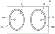
Fig. 7 to 16 each show a planar configuration example of the vibration control member 16. Here, it is assumed that on the rear surface of the display unit 11, the position facing the vibrator 21 (first vibrator) is a vibration point 11A (first vibration point), and the position facing the vibrator 22 (second vibrator) is a vibration point 11B (second vibration point). In this case, the vibration control member 16 divides the rear surface of the display unit 11 into a partition region R1 (first partition region) including the vibration point 11A and a partition region R2 (second partition region) including the vibration point 11B. The vibration control member 16 may include, for example, a vibration control member 16L (first vibration control member) forming the dividing region R1 and a vibration control member 16R (second vibration control member) forming the dividing region R2.
The vibration control member 16L may include, for example, a plurality of convex portions 16a (first convex portions) that protrude toward the vibration point 11A, as shown in fig. 7 and 9 to 12. The vibration control member 16R may include, for example, a plurality of convex portions 16B (second convex portions) protruding toward the vibration point 11B, as shown in fig. 7 and 9 to 12. The vibration control member 16L may include, for example, one convex portion 16a protruding toward the vibration point 11A, as shown in fig. 8. The vibration control member 16R may include, for example, one convex portion 16B protruding toward the vibration point 11B, as shown in fig. 8. From the viewpoint of suppressing standing waves, the vibration control member 16L preferably includes many convex portions 16a, and the vibration control member 16R preferably includes many convex portions 16 a.
The vibration control member 16L may be formed, for example, to have a partition region R1 as a closed region on the rear surface of the display unit 11, as shown in fig. 7 to 11. The vibration control member 16R may be formed, for example, to have a partition region R2 as a closed region on the rear surface of the display unit 11, as shown in fig. 7 to 11. The vibration control member 16L and the vibration control member 16R may be formed, for example, to have a partition region R1 and a partition region R2 that communicate with each other and are one closed region on the rear surface of the display unit 11, as shown in fig. 12.
The vibration control member 16L may be shaped, for example, in a circular ring shape or a polygonal ring shape without a position protruding toward the vibration point 11A, as shown in fig. 13 and 14. The vibration control member 16R may be shaped, for example, in a circular ring shape or a polygonal ring shape without a position protruding toward the vibration point 11B, as shown in fig. 13 and 14. The vibration control member 16L may have, for example, a shape in which a ring-shaped convex portion is divided into two or more portions, as shown in fig. 15 and 16. The vibration control member 16R may have a shape in which, for example, a ring-shaped convex portion is divided into two or more portions, as shown in fig. 15 and 16. The vibration control member 16L may have, for example, a different aspect ratio than 1:1 as shown in fig. 7 to 14. The vibration control member 16R may have, for example, a different aspect ratio than 1:1, as shown in fig. 7 to 14. The vibration control member 16L is provided, for example, near the left edge of the display unit 11 as shown in fig. 10, 17, and 18, and the vibration control member 16R is provided, for example, near the right edge of the display unit 11 as shown in fig. 10, 17, and 18. In this case, the plurality of convex portions 16a may be provided in the vibration control member 16L in the vicinity of the left edge of the display unit 11, and the plurality of convex portions 16b may be provided in the vibration control member 16R in the vicinity of the right edge of the display unit 11. The vibration control member 16L may be, for example, bilaterally symmetrical when viewed from the middle of the display unit 11, as shown in fig. 7 to 18. The vibration control member 16R may be, for example, bilaterally symmetrical when viewed from the middle of the display unit 11, as shown in fig. 7 to 18. The vibration control member 16L may be, for example, vertically symmetrical when viewed from the middle of the display unit 11, as shown in fig. 7, 10, 13 to 18. The vibration control member 16R may be, for example, vertically symmetrical when viewed from the middle of the display unit 11, as shown in fig. 7, 10, 13 to 18.
The vibration control member 16 may be formed, for example, between the vibration point 11A and the vibration point 11B, as shown in fig. 19 and 20. The vibration control member 16 may be formed, for example, to have an X shape having a center disposed on a straight line connecting the vibration point 11A and the vibration point 11B, as shown in fig. 19. The vibration control member 16 may be formed, for example, to have an I-shape having an extending direction intersecting (e.g., orthogonal to) a straight line connecting the vibration point 11A and the vibration point 11B, as shown in fig. 20.
The vibration control member 16L and the vibration control member 16R may have, for example, left-right symmetrical shapes, as shown in fig. 7 to 14. It should be noted that the vibration control member 16 may be disposed away from the surface of the inner panel 12, as shown in fig. 21, for example, as long as the vibration control member 16 has the above-described function.
[ Effect ]
Next, the effects of the flat panel speaker 1 according to the present embodiment are described.
The thickness and weight of displays have been rapidly reduced. Therefore, the thickness and weight of the speaker have also been reduced, and it has been proposed to use a Flat Panel Speaker (FPS) instead of or together with the cone speaker. A series of uses of the flat panel speaker are expected to increase, and the flat panel speaker can be applied not only to a display but also to a billboard or the like displayed at an exhibition or the like.
However, in a typical flat panel speaker, there are cases where the sound quality is degraded due to the influence of standing waves occurring in the vibration plate, for example, cases where flare occurs in the sound and cases where sound of a specific frequency band is not easily emitted.
Meanwhile, in the flat panel speaker 1 according to the present embodiment or in the display device incorporating the flat panel speaker 1, the plurality of vibrators 21 and 22 are disposed on the rear surface of the display unit 11 while avoiding a position most likely to vibrate in the entire audio frequency range when vibration is generated in the display unit 11 by the plurality of vibrators 21 and 22. Therefore, a large standing wave is not easily generated with respect to the display unit 11. As a result, sound quality degradation can be suppressed.
Further, in the present embodiment, the vibrators 21 and 22 are provided so as to avoid a position where vibration is least likely to occur in the entire audio frequency range when vibration is generated in the display unit 11 by the vibrators 21 and 22. This makes it possible to generate vibration for the display unit 11.
Further, in the present embodiment, in the case where the plurality of vibrators 21 and 22 are provided at positions having an inseparable ratio in the lateral direction and the vertical direction of the display unit 11, a large standing wave is less likely to occur with respect to the display unit 11. As a result, sound quality degradation can be suppressed.
In addition, in the flat panel speaker 1 according to the present embodiment or the display device incorporating the flat panel speaker 1, the rear surface of the display unit 11 is divided into the partition region R1 including the vibration point 11A and the partition region R2 including the vibration point 11B by the vibration control member 16 fixed to the rear surface of the display unit 11. This prevents standing waves caused by interference between the vibration generated in the display unit 11 by the vibrator 21 and the vibration generated in the display unit 11 by the vibrator 22. As a result, sound quality degradation can be suppressed.
Also, in the present embodiment, in the case where the vibration control member 16L is provided with one or more convex portions 16a protruding toward the vibration point 11A, and the vibration control member 16R is provided with one or more convex portions 16B protruding toward the vibration point 11B, the occurrence of standing waves is prevented by the one or more convex portions 16a and the one or more convex portions 16B. As a result, sound quality degradation can be suppressed.
Further, in the present embodiment, in the case where the vibration control member 16L is formed to have the partition region R1 as a closed region on the rear surface of the display unit 11, standing waves caused by vibrations generated in the display unit 11 by the vibrator 21 are prevented. Further, in the present embodiment, in the case where the vibration control member 16R is formed to have the partition region R2 as a closed region on the rear surface of the display unit 11, standing waves caused by vibrations generated in the display unit 11 by the vibrator 22 are prevented. Therefore, also in this case, the sound quality degradation can be suppressed. It should be noted that even in the case where the vibration control member 16L and the vibration control member 16R are formed on the rear surface of the display unit 11 to have the partition region R1 and the partition region R2 which communicate with each other and are one closed region, the standing wave caused by the vibration generated in the display unit 11 by the vibrator 21 is suppressed, and the standing wave caused by the vibration generated in the display unit 11 by the vibrator 22 is suppressed. Therefore, also in this case, the sound quality degradation can be suppressed.
In addition, in the present embodiment as well, in the case where the vibration control member 16L is shaped in a circular ring shape or a polygonal ring shape without a position protruding toward the vibration point 11A, standing waves caused by the vibration generated in the display unit 11 by the vibrator 21 are prevented. Further, also in the case where the vibration control member 16R is shaped like a circular ring or a polygonal ring without a position protruding toward the vibration point 11B, standing waves caused by the vibration generated in the display unit 11 by the vibrator 22 are prevented. Therefore, also in this case, the sound quality degradation can be suppressed.
In addition, in the present embodiment, also in the case where the vibration control member 16 is formed between the vibration point 11A and the vibration point 11B, by devising the layout of the vibration control member 16, a standing wave caused by interference between the vibration generated in the display unit 11 by the vibrator 21 and the vibration generated in the display unit 11 by the vibrator 22 is prevented. As a result, sound quality degradation can be suppressed.
Also, in the present embodiment, in the case where the vibration control member 16L is provided near the left edge of the display unit 11, and the vibration control member 16R is provided near the right edge of the display unit 11, and further, the plurality of convex portions 16a are provided near the left edge of the display unit 11 in the vibration control member 16L, and the plurality of convex portions 16b are provided near the right edge of the display unit 11 in the vibration control member 16R, the directivity of the sound wave can be adjusted by adjusting the sizes of the convex portions 16a and 16b, and the like.
In addition, in the present embodiment, in the case where the aspect ratio of the vibration control member 16L is different from 1:1, and further, the aspect ratio of the vibration control member 16R is different from 1:1, a large standing wave with respect to the display unit 11 is less likely to occur. As a result, sound quality degradation can be suppressed.
Also, in the present embodiment, in the case where the vibration control members 16L and 16R each have a shape in which the annular convex portion is divided into two or more portions, the standing wave can be allowed to escape from the gap formed in each of the vibration control members 16L and 16R. Therefore, a large standing wave with respect to the display unit 11 does not easily occur. As a result, sound quality degradation can be suppressed.
Further, in the present embodiment, in the case where each of the vibration control members 16L and 16R is symmetrical left and right and symmetrical up and down when viewed from the middle of the flat plate 11, the characteristics of the sound generated by the vibrator 21 and the characteristics of the sound generated by the vibrator 22 can be made equivalent to each other. As a result, sound quality can be improved.
Further, in the present embodiment, in the case where the edge of the display unit 11 is circular or in the case where the four corners of the display unit 11 are rounded, a large standing wave with respect to the display unit 11 is unlikely to occur. As a result, sound quality degradation can be suppressed.
In the present embodiment, when the vibration control member 16 is configured by a flexible member having a low self-standing property, reflection of the sound wave by the vibration control member 16 is reduced. This makes the in-plane distribution of the standing wave more nearly flat (drop), so that the sound quality degradation can be suppressed. Further, in the present embodiment, also in the case where the vibration control member 16 includes a sponge as a flexible member poor in self-standing property, and further includes the adhesive layer 16f or the adhesive layer 16a that fixes the sponge to the rear surface of the display unit 11, reflection of the sound wave in the vibration control member 16 is attenuated. This makes the in-plane distribution of the standing wave closer, so that the sound quality degradation can be suppressed. Further, in the present embodiment, also in the case where the vibration control member 16 includes an adhesive or a bonding agent as a flexible member having poor self-standing properties, reflection of sound waves in the vibration control member 16 is attenuated. This makes the in-plane distribution of the standing wave more nearly flat, so that the sound quality degradation can be suppressed.
In addition, in the present embodiment, in the case where the vibrators (the vibrators 21 and 22) are each fixed to the inner panel 12 provided to face the display unit 11 (a predetermined gap is formed between the display unit 11 and the inner panel 12), the vibration of each vibrator (the vibrators 21 and 22) can be efficiently transmitted to the display unit 11. Therefore, the sound quality degradation can be suppressed.
Further, in the present embodiment, in the case where the vibration control member 16 is in contact with the inner panel 12, the vibration control function of the vibration control member 16 can be further increased. Therefore, the sound quality degradation can be suppressed. It should be noted that in the present embodiment, in the case where the vibration control member 16 is provided away from the inner panel 12, it is possible to expect the vibration control effect by its own weight.
<2 > modification of the first embodiment
In the foregoing embodiment, the support portion 40 and the rotation portion 50 may be omitted, for example, as shown in fig. 22 and 23. In this case, however, it is preferable that the rear bottom case 19 is provided with a recess 32 for hanging the flat panel speaker 1 on a hook or the like provided on a wall. It should be noted that in the case where the flat panel speaker 2 is placed on a table top stand, the above-mentioned recess 32 may not be present.
<3, second embodiment >
[ Structure ]
Next, a flat panel speaker 2 according to a second embodiment of the present disclosure is described. Fig. 24 shows a side configuration example of the flat panel speaker 2 according to the present embodiment. Fig. 25 shows a rear surface configuration example of the flat panel speaker 2 in fig. 24. The flat speaker 2 also serves as a display device for displaying images. In other words, it can be said that the display device includes the built-in flat panel speaker 2 and is configured to be able to output sound from a display surface on which an image is displayed.
The flat panel speaker 2 includes a panel portion 60 serving as a vibration plate, for example, and a vibration portion 70 provided on a rear surface of the panel portion 60 and causing the panel portion 60 to vibrate. The flat panel speaker 2 further includes, for example, a support portion 80 in which a signal processing circuit 81 for controlling the vibration portion 70 is built. The supporting portion 80 is fixed to the rear bottom case 69 by the rotating portion 90. The rotation part 90 adjusts the inclination of the panel part 60 when the support part 80 supports the rear surface of the panel part 60. The rotation portion 90 is configured by, for example, a hinge that rotatably supports the panel portion 60 and the support portion 80.
Fig. 26 shows a configuration example of the back surface of the flat panel speaker 2 when the rear bottom case 69 is removed. Fig. 27 shows a cross-sectional configuration example taken along line a-a in fig. 26.
The panel portion 60 includes, for example: a display unit 61 having a thin plate-like shape to display an image; and a vibration control member 16 fixed to a rear surface of the display unit 61. The vibration control means 16 has a function of preventing standing waves caused by interference between the vibration generated in the display unit 61 by the vibrator 21 and the vibration generated in the display unit 61 by the vibrator 22. The vibration control member 16 has a configuration similar to that in the foregoing embodiment.
As in the foregoing embodiment, the vibrating portion 70 includes, for example, two vibrators (the vibrators 21 and 22). The vibrator 21 is disposed on the left side when the display unit 61 is viewed from the rear surface. The vibrator 22 is disposed on the right side when the display unit 61 is viewed from the rear surface. The vibrating section 70 also includes a wiring board 71 that electrically couples together the signal processing circuit 81 and the two vibrators (the vibrators 21 and 22). For example, a flexible wiring board is coupled to the wiring board 71, and the two vibrators (the vibrators 21 and 22) and the signal processing circuit 81 are electrically coupled through the flexible wiring board.
The vibrating portion 70 further includes, for each vibrator, for example, a fixing portion 72, a fixing member 73, and the vibration transmission member 24. The fixing portion 72 has, for example, an opening 72a, and the opening 72a is provided to fix the vibrator 21 or the vibrator 22 in a state where the vibrator 21 or the vibrator 22 is inserted therein. For example, the vibrators (the vibrators 21 and 22) are each fixed to the rear surface of the display unit 61 by a fixing portion 72 and a fixing member 73. The vibrators (the vibrators 21 and 22) are each fixed by a fixing member 73 to a position different from a position facing the vibrators (the vibrators 21 and 22) with respect to the rear surface of the display unit 61. In addition to fixing the vibrator 21 or the vibrator 22 to the rear surface of the display unit 61, the fixing portion 73 may function as, for example, a heat sink that radiates heat generated by the vibrator 21 or the vibrator 22. The fixing member 73 is used to fix the display unit 61 and the fixing portion 72 to each other. The fixing member 73 may have, for example, flexibility to the extent of avoiding damping of vibration of the display unit 61 when the display unit 61 vibrates. The fixing member 73 is configured of, for example, a sponge having an adhesive layer on each of both faces.
[ Effect ]
In the flat panel speaker 2 according to the present embodiment or the display device incorporating the flat panel speaker 2, the rear surface of the display unit 61 is divided into a partition region R1 including the vibration point 11A and a partition region R2 including the vibration point 11B by the vibration control member 16 fixed to the rear surface of the display unit 61. This prevents standing waves caused by interference between the vibration generated in the display unit 61 by the vibrator 21 and the vibration generated in the display unit 61 by the vibrator 22. As a result, sound quality degradation can be suppressed. It should be noted that the vibration control member 16 in the present embodiment has effects similar to those obtained by the vibration control member 16 in the foregoing embodiment.
In addition, in the present embodiment, the vibrators (the vibrators 21 and 22) are each fixed at a position different from a position facing the vibrator (the vibrators 21 and 22) with respect to the rear surface of the display unit 61. Therefore, the vibrators (the vibrators 21 and 22) each vibrate together with the display unit 61, and therefore, the amplitude attributable to resonance increases, which makes it possible to increase the output in the low-frequency region.
<4 > variation common to the respective embodiments
[ modification A ]
For example, in each of the foregoing embodiments and modifications thereof, a flat plate 17 or a flat plate 63 having no display function may be provided instead of the display unit 11 or the display unit 61, as shown in fig. 28, 29, and 30. In this case, effects similar to those in each of the foregoing embodiment and its modifications can also be obtained.
[ modification B ]
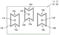
In each of the foregoing embodiments and modifications thereof, the number of vibrators (actuators) may be three or more. For example, in the first embodiment and its modified examples described above, the vibrator 20 may include three vibrators (the vibrators 21 and 22 and the vibrator 25), for example, as shown in fig. 31. Further, for example, in the above-described second embodiment and its modified examples, the vibrator 70 may include three vibrators (the vibrators 21, 22, and 25), for example, as shown in fig. 32. In these cases, the third vibrator (vibrator 25) is located, for example, between the vibrator 21 and the vibrator 22, as shown in fig. 31 and 32. The vibrator 25 (actuator) has a configuration similar to that of the vibrator 21.
Fig. 33 shows a back surface structure example of the vibration control member 16 in the present modification. In the present modification, in the rear surface of the display unit 11, the display unit 61, the flat plate 17, or the flat plate 63, a position facing the vibrator 25 is set as the vibration point 11D. In this case, the vibration control member 16D partitions the rear surface of the display unit 11, the display unit 61, the flat plate 17, or the flat plate 63 into a partition region R3 including the vibration point 11D, and is fixed to the rear surface of the display unit 11, the display unit 61, the flat plate 17, or the flat plate 63. The vibration control member 16D has a configuration similar to that of the vibration control member 16L or the vibration control member 16R. Therefore, in the present modification as well, effects similar to those in each of the foregoing embodiment and its modifications can be obtained.
[ modification C ]
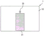
In each of the foregoing embodiments and the modifications thereof, the number of vibrators (actuators) may be one. For example, the vibrator 20 or the vibrator 70 may include one vibrator (vibrator 25), for example, as shown in fig. 34 and 35. In this case, when the vibrator 25 generates vibration in the display unit 11, the display unit 61, the flat panel 17, or the flat panel 63, the vibrator 25 is disposed so as to avoid a position most likely to vibrate in the entire audio frequency range. Further, when the vibrator 25 generates vibration in the display unit 11, the display unit 61, the flat panel 17, or the flat panel 63, the vibrator 25 is disposed so as to avoid a position least likely to vibrate in the entire audio frequency range. The vibration of the display unit 11, the display unit 61, the flat panel 17, or the flat panel 63 is determined by measuring the vibration of the entire surface of the display unit 11, the display unit 61, the flat panel 17, or the flat panel 63 over the entire audio frequency range, for example, using a laser doppler vibrometer. The vibrator 25 is disposed at a position having an inseparable ratio in the lateral and vertical directions of the display unit 11, the display unit 61, the flat plate 17, or the flat plate 63. Examples of "non-divisible ratios" include 3:4, 5:7, 3:7, 2:5, and 7: 11.
In the present modification, in the rear surface of the display unit 11, the display unit 61, the flat plate 17, or the flat plate 63, a position facing the vibrator 25 is set as the vibration point 11D. In this case, the vibration control member 16D partitions the rear surface of the display unit 11, the display unit 61, the flat plate 17, or the flat plate 63 into a partition region R3 including the vibration point 11D, and is fixed to the rear surface of the display unit 11, the display unit 61, the flat plate 17, or the flat plate 63.
In the present modification, the vibration control member 16D has a function of preventing standing waves caused by the vibration generated by the vibrator 25 in the display unit 11, the display unit 61, the flat plate 17, or the flat plate 63. The vibration control member 16D may be configured of, for example, a material that allows control of reflection of vibration generated by the vibrator 25 in a sound wave region (20Hz or more). Further, the vibration control member 16D may be configured, for example, from a material that allows absorption of vibration or reverberation generated by the vibrator 25.
The vibration control member 16D may include, for example, a plurality of convex portions 16D (third convex portions) that protrude toward the vibration point 11D, as shown in fig. 36 and 38 to 40. The vibration control member 16D may include, for example, one convex portion 16D protruding toward the vibration point 11D, as shown in fig. 37. The vibration control member 16D may be formed, for example, to have a partition region R3 as a closed region on the rear surface of the display unit 11, the display unit 61, the flat plate 17, or the flat plate 63, as shown in fig. 36 to 42. The vibration control member 16D may be shaped, for example, in a circular ring shape or a polygonal ring shape without a position protruding toward the vibration point 11D, as shown in fig. 41 and 42. It should be noted that the vibration control member 16D may be disposed away from the surface of the inner plate 12 as long as the vibration control member 16D has a function similar to that of the vibration control member 16.
In the present modification, the rear surface of the display unit 11, the display unit 61, the flat plate 17, or the flat plate 63 is divided into the divided regions R3 including the vibration points 11D by the vibration control member 16D fixed to the rear surface of the display unit 11, the display unit 61, the flat plate 17, or the flat plate 63. This prevents standing waves caused by the vibration generated by the vibrator 25 in the display unit 11, the display unit 61, the flat plate 17, or the flat plate 63. As a result, sound quality degradation can be suppressed. It should be noted that the vibration control member 16D in the present modification has effects similar to those obtained by the vibration control member 16 in the foregoing embodiment.
In the present modification, the vibration control member 16D may be formed on substantially the entire rear surface of the display unit 61, the flat plate 17, or the flat plate 63. For example, as shown in fig. 43, in the present modification, the vibration control member 16D may be formed in a wide range of the rear surface of the display unit 61, the flat plate 17, or the flat plate 63.
Although the present disclosure has been described above with reference to the embodiments and the modifications thereof, the present disclosure is not limited to the foregoing embodiments and the like, and may be modified in various ways. It should be noted that the effects described herein are merely exemplary. The effects of the present disclosure are not limited to the effects described herein. The present disclosure may have effects other than those described herein.
It should be noted that the present disclosure may adopt the following configuration.
(1) A flat panel speaker, comprising:
a flat plate; and
a plurality of vibrators disposed on a rear surface of the flat plate and vibrating the flat plate,
the plurality of vibrators are arranged to avoid a position where the plurality of vibrators most easily vibrate in the entire audio frequency range when generating vibrations in the flat panel.
(2) The flat panel speaker according to (1), wherein the plurality of vibrators are provided so as to avoid a position least likely to vibrate in the entire audio frequency range when the plurality of vibrators generate vibrations in the flat panel.
(3) The flat panel speaker according to (1) or (2), wherein the plurality of vibrators are provided at positions having an inseparable ratio in a left-right direction and a top-bottom direction of the flat panel.
(4) The flat panel speaker according to any one of (1) to (3), comprising:
a flat plate;
a plurality of vibrators disposed on a rear surface of the flat plate and vibrating the flat plate; and
a vibration control member fixed to a rear surface of the flat plate, and dividing the rear surface of the flat plate into a first divided region including a first vibration point and a second divided region including a second vibration point when a position facing a first vibrator of the plurality of vibrators is set as the first vibration point and a position facing a second vibrator different from the first vibrator is set as the second vibration point on the rear surface of the flat plate.
(5) The flat panel speaker according to (4), wherein the vibration control member has a function of preventing a standing wave caused by interference between the vibration generated in the flat panel by the first vibrator and the vibration generated in the flat panel by the second vibrator.
(6) The flat panel speaker according to (4) or (5), wherein,
the vibration control member includes a first vibration control member forming a first partitioned area and a second vibration control member forming a second partitioned area,
the first vibration control member includes one or more first convex portions protruding toward the first vibration point, and
the second vibration control member includes one or more second convex portions protruding toward the second vibration point.
(7) The flat panel speaker according to (6), wherein,
the first partition is disposed near a left edge of the flat plate,
the second spaced-apart region is disposed near a right edge of the plate,
the one or more first protrusions are disposed near a left edge of the flat plate in the first divided region, and
the one or more second protrusions are disposed near a right edge of the flat plate in the second partition region.
(8) The flat panel speaker according to any one of (5) to (7),
the first divided region has an aspect ratio different from 1:1, and
the aspect ratio of the second partition region is different from 1: 1.
(9) The flat panel speaker according to any one of (4) to (8), wherein the vibration control member is configured by a flexible member poor in self-standing property, the vibration control member including a sponge as the flexible member and further including an adhesive layer or an adhesive layer that fixes the sponge to the rear surface of the flat panel.
(10) The flat panel speaker according to any one of (4) to (8), wherein the vibration control member is configured by a flexible member poor in self-standing property, the vibration control member including a bonding agent or an adhesive as the flexible member.
(11) The flat panel speaker according to (5), further comprising a facing plate disposed to face the flat panel with a predetermined gap formed therebetween,
each vibrator is fixed to the facing plate.
(12) The flat panel speaker according to (11), wherein the vibration control member is in contact with the facing plate.
(13) The flat panel speaker according to (11), wherein the vibration control member is disposed away from the facing plate.
(14) The flat panel speaker according to (5), wherein each vibrator is fixed at a position different from a position facing the vibrator with respect to a rear surface of the flat panel.
(15) A flat panel speaker, comprising:
a flat plate; and
a vibrator disposed on a rear surface of the flat plate and vibrating the flat plate,
the vibrator is arranged to avoid a position where it is easiest to vibrate in the entire audio frequency range when vibration is generated in the flat panel by the vibrator.
(16) The flat panel speaker according to (15), further comprising a vibration control member that is fixed to the rear surface of the display unit and divides the rear surface of the display unit into partitioned areas including vibration points when a position facing the vibrator is set as the vibration point on the rear surface of the display unit.
(17) The flat panel speaker according to (16), wherein the vibration control member has a function of preventing a standing wave caused by vibration generated in the flat panel by the vibrator.
(18) A display device, comprising:
a display unit having a sheet-like shape and displaying an image; and
a plurality of vibrators disposed on a rear surface of the display unit and vibrating the display unit,
a plurality of vibrators arranged to avoid a position where the plurality of vibrators most easily vibrate in the entire audio frequency range when generating vibrations in the display unit.
(19) A display device, comprising:
a display unit having a sheet-like shape and displaying an image; and
a vibrator disposed on a rear surface of the display unit and causing the display unit to vibrate,
the vibrator is arranged to avoid a position most easily vibrated in the entire audio frequency range when the vibration is generated in the display unit by the vibrator.
This application claims the benefit of japanese priority patent application JP2016-253665 filed on day 12/27/2016 and japanese patent application JP2017-099449 filed on day 19/5/2017 on day 19/2017 on the office, both of which are hereby incorporated by reference in their entirety.
It should be understood by those skilled in the art that various modifications, combinations, sub-combinations and alterations may be made according to design requirements and other factors insofar as they come within the scope of the appended claims or the equivalents thereof.
Claims (16)
1. A flat panel speaker, comprising:
a flat plate;
a plurality of vibrators disposed on a rear surface of the flat plate and vibrating the flat plate,
the plurality of vibrators are arranged so as to avoid a position most likely to vibrate in the entire audio frequency range when vibrations are generated in the flat panel by the plurality of vibrators, wherein the position most likely to vibrate is a position of an antinode of a maximum standing wave occurring in the flat panel;
a facing plate arranged to face the flat plate with a predetermined gap formed therebetween; and
a vibration control member that is fixed to a rear surface of the flat plate and is in contact with the facing plate, and that, when a position facing the first vibrator is set as a first vibration point and a position facing a second vibrator different from the first vibrator is set as a second vibration point on the rear surface of the flat plate, divides the rear surface of the flat plate into a first divided region including the first vibration point and a second divided region including the second vibration point,
wherein the vibration control member includes a first vibration control member forming the first partition region and a second vibration control member forming the second partition region.
2. The flat panel speaker of claim 1, wherein the plurality of vibrators are arranged to avoid locations least prone to vibration over the entire audio frequency range when vibrations are generated in the flat panel by the plurality of vibrators.
3. The flat panel speaker of claim 1, wherein the plurality of vibrators are arranged at positions having an indivisible ratio in the left-right direction and the up-down direction of the flat panel.
4. The flat panel speaker according to claim 1, wherein the vibration control member has a function of preventing a standing wave caused by interference between the vibration generated in the flat panel by the first vibrator and the vibration generated in the flat panel by the second vibrator.
5. The flat panel speaker of claim 1,
the first vibration control member includes one or more first convex portions protruding toward the first vibration point, and
the second vibration control member includes one or more second convex portions protruding toward the second vibration point.
6. The flat panel speaker of claim 5,
the first separation region is disposed adjacent to a left edge of the flat plate,
the second spaced-apart region is disposed adjacent to a right edge of the flat plate,
the one or more first protrusions are disposed adjacent to a left edge of the flat plate in the first partition region, and
the one or more second protrusions are disposed adjacent to a right edge of the flat plate in the second spaced-apart region.
7. The flat panel speaker of claim 4,
the first divided region has an aspect ratio different from 1:1, and
the second partition region has an aspect ratio different from 1: 1.
8. The flat panel speaker of claim 1, wherein the vibration control member is constituted by a flexible member poor in self-supporting property, the vibration control member including a sponge as the flexible member and further including an adhesive layer or an adhesive layer fixing the sponge to the rear surface of the flat panel.
9. The flat panel speaker of claim 1, wherein the vibration control member is constituted by a flexible member poor in self-supporting property, the vibration control member including an adhesive or an adhesive as the flexible member.
10. The flat panel speaker of claim 4,
each of the vibrators is fixed to the facing plate.
11. The flat panel speaker of claim 10, wherein the vibration control member is disposed away from the facing plate.
12. The flat panel speaker of claim 4, wherein each of the vibrators is fixed at a position different from a position facing the vibrator with respect to a rear surface of the flat panel.
13. A flat panel speaker, comprising:
a flat plate;
a vibrator disposed on a rear surface of the flat plate and vibrating the flat plate,
the vibrator is arranged to avoid a position most likely to vibrate in the entire audio frequency range when vibration is generated in the flat panel by the vibrator, wherein the position most likely to vibrate is a position of an antinode of a maximum standing wave occurring in the flat panel;
a facing plate arranged to face the flat plate with a predetermined gap formed therebetween; and
a vibration control member that is fixed to a rear surface of the flat plate and is in contact with the facing plate, and partitions the rear surface of the flat plate into a partition area including a vibration point when a position facing the vibrator is set as the vibration point on the rear surface of the flat plate.
14. The flat panel speaker of claim 13, wherein the vibration control member has a function of preventing standing waves caused by vibration generated in the flat panel by the vibrator.
15. A display device, comprising:
a display unit which is shaped into a thin plate and displays an image;
a plurality of vibrators disposed on a rear surface of the display unit and vibrating the display unit;
the plurality of vibrators are arranged so as to avoid a position most likely to vibrate in the entire audio frequency range when vibration is generated in the display unit by the plurality of vibrators, wherein the position most likely to vibrate is a position of an antinode of a maximum standing wave occurring in the display unit;
a facing plate arranged to face the display unit with a predetermined gap formed therebetween; and
a vibration control member fixed to a rear surface of the display unit and in contact with the facing plate, and dividing the rear surface of the display unit into a first divided region including a first vibration point and a second divided region including a second vibration point when a position facing the first vibrator is set as the first vibration point and a position facing a second vibrator different from the first vibrator is set as the second vibration point on the rear surface of the display unit,
wherein the vibration control member includes a first vibration control member forming the first partition region and a second vibration control member forming the second partition region.
16. A display device, comprising:
a display unit which is shaped into a thin plate and displays an image;
a vibrator disposed on a rear surface of the display unit and vibrating the display unit,
the vibrator is arranged to avoid a position most likely to vibrate in the entire audio frequency range when vibration is generated in the display unit by the vibrator, wherein the position most likely to vibrate is a position of an antinode of a maximum standing wave occurring in the display unit;
a facing plate arranged to face the display unit with a predetermined gap formed therebetween; and
a vibration control member fixed to a rear surface of a display unit and in contact with the facing plate, and when a position facing the vibrator is set as a vibration point on the rear surface of the display unit, separating the rear surface of the display unit into a separation region including the vibration point.
Applications Claiming Priority (5)
| Application Number | Priority Date | Filing Date | Title |
|---|---|---|---|
| JP2016253665 | 2016-12-27 | ||
| JP2016-253665 | 2016-12-27 | ||
| JP2017-099449 | 2017-05-19 | ||
| JP2017099449 | 2017-05-19 | ||
| PCT/JP2017/041065 WO2018123310A1 (en) | 2016-12-27 | 2017-11-15 | Flat panel speaker, and display device |
Publications (2)
| Publication Number | Publication Date |
|---|---|
| CN108702573A CN108702573A (en) | 2018-10-23 |
| CN108702573B true CN108702573B (en) | 2021-11-26 |
Family
ID=62708105
Family Applications (1)
| Application Number | Title | Priority Date | Filing Date |
|---|---|---|---|
| CN201780012260.2A Active CN108702573B (en) | 2016-12-27 | 2017-11-15 | Flat panel speaker and display device |
Country Status (5)
| Country | Link |
|---|---|
| US (1) | US11115740B2 (en) |
| EP (1) | EP3407623B1 (en) |
| JP (4) | JP6489291B2 (en) |
| CN (1) | CN108702573B (en) |
| WO (1) | WO2018123310A1 (en) |
Families Citing this family (21)
| Publication number | Priority date | Publication date | Assignee | Title |
|---|---|---|---|---|
| KR102455559B1 (en) * | 2017-12-26 | 2022-10-14 | 엘지디스플레이 주식회사 | Display apparatus |
| KR102548686B1 (en) * | 2018-06-28 | 2023-06-27 | 엘지디스플레이 주식회사 | Display apparatus |
| KR102594577B1 (en) * | 2018-08-22 | 2023-10-25 | 엘지디스플레이 주식회사 | Display apparatus |
| KR102530589B1 (en) * | 2018-09-20 | 2023-05-08 | 엘지디스플레이 주식회사 | Display apparatus and computing apparatus using the same |
| KR102514184B1 (en) * | 2018-09-28 | 2023-03-24 | 엘지디스플레이 주식회사 | Display apparatus |
| KR102540217B1 (en) | 2018-10-23 | 2023-06-02 | 엘지디스플레이 주식회사 | Display apparatus |
| JP2020092306A (en) * | 2018-12-04 | 2020-06-11 | 株式会社デンソーテン | Speaker device |
| US20220217469A1 (en) | 2019-04-16 | 2022-07-07 | Sony Group Corporation | Display Device, Control Method, And Program |
| CN113711622A (en) | 2019-04-23 | 2021-11-26 | 索尼集团公司 | Signal processing device, signal processing method, program, and video display device |
| WO2020226000A1 (en) | 2019-05-08 | 2020-11-12 | ソニー株式会社 | Signal processing device, signal processing method, program, and video display device |
| KR102653775B1 (en) * | 2019-07-04 | 2024-04-01 | 엘지디스플레이 주식회사 | Display apparatus |
| JPWO2021014933A1 (en) | 2019-07-19 | 2021-01-28 | ||
| JPWO2021020157A1 (en) * | 2019-07-31 | 2021-02-04 | ||
| JP7269135B2 (en) * | 2019-08-29 | 2023-05-08 | フォルシアクラリオン・エレクトロニクス株式会社 | vibration output device |
| DE112020005478T5 (en) | 2019-11-06 | 2022-10-13 | Sony Group Corporation | SIGNAL PROCESSING DEVICE, SIGNAL PROCESSING METHOD, PROGRAM AND PICTURE DISPLAY DEVICE |
| KR20210086304A (en) * | 2019-12-31 | 2021-07-08 | 엘지디스플레이 주식회사 | Display apparatus |
| CN114902692A (en) | 2020-01-24 | 2022-08-12 | 索尼集团公司 | Display device and speaker device |
| KR20220019140A (en) | 2020-08-06 | 2022-02-16 | 삼성디스플레이 주식회사 | Display device |
| JP7234341B2 (en) * | 2020-12-31 | 2023-03-07 | エルジー ディスプレイ カンパニー リミテッド | Device and vibration generator |
| CN113225649B (en) * | 2021-04-26 | 2022-07-12 | 深圳创维-Rgb电子有限公司 | Audio sounding propagation system and audio equipment with same |
| WO2023095735A1 (en) * | 2021-11-24 | 2023-06-01 | Agc株式会社 | Diaphragm with exciter, and vehicle window glass |
Citations (6)
| Publication number | Priority date | Publication date | Assignee | Title |
|---|---|---|---|---|
| CN1195454A (en) * | 1995-09-02 | 1998-10-07 | 新型转换器有限公司 | Acoustic device |
| JP2010081142A (en) * | 2008-09-25 | 2010-04-08 | Panasonic Electric Works Co Ltd | Panel-shaped speaker |
| WO2014184994A1 (en) * | 2013-05-15 | 2014-11-20 | ソニー株式会社 | Audio output device, audio output method, and video display device |
| CN104469567A (en) * | 2013-09-25 | 2015-03-25 | 鸿富锦精密工业(深圳)有限公司 | Loudspeaker and displayer |
| EP2884765A1 (en) * | 2012-08-10 | 2015-06-17 | Kyocera Corporation | Acoustic generator, acoustic generation device, and electronic apparatus |
| CN105096778A (en) * | 2014-05-20 | 2015-11-25 | 三星显示有限公司 | Display apparatus |
Family Cites Families (26)
| Publication number | Priority date | Publication date | Assignee | Title |
|---|---|---|---|---|
| JPS5069527U (en) | 1973-10-26 | 1975-06-20 | ||
| JPS5588499A (en) | 1978-12-26 | 1980-07-04 | Sony Corp | Flat-type speaker |
| JPS6140099U (en) | 1984-08-16 | 1986-03-13 | オンキヨー株式会社 | piezoelectric speaker |
| CN1655645A (en) | 1995-09-02 | 2005-08-17 | 新型转换器有限公司 | Loudspeaker and apparatus using loudspeaker |
| CN101031162B (en) | 1998-01-16 | 2012-09-05 | 索尼公司 | Speaker apparatus |
| IL136820A0 (en) | 1998-01-20 | 2001-06-14 | New Transducers Ltd | Active acoustic devices comprising panel members |
| JP3838962B2 (en) | 2002-10-07 | 2006-10-25 | Necアクセステクニカ株式会社 | Manufacturing apparatus and manufacturing method for speaker-integrated display |
| JP2004343362A (en) | 2003-05-15 | 2004-12-02 | Alps Electric Co Ltd | Planar speaker |
| JP4177249B2 (en) | 2003-12-26 | 2008-11-05 | アルプス電気株式会社 | Sound playback device |
| GB0405475D0 (en) | 2004-03-11 | 2004-04-21 | New Transducers Ltd | Loudspeakers |
| JP4086823B2 (en) | 2004-09-03 | 2008-05-14 | Necアクセステクニカ株式会社 | Panel type speaker, speaker-integrated display and electronic device |
| JP4032395B2 (en) | 2005-03-07 | 2008-01-16 | ミネベア株式会社 | Exciters and flat speakers |
| JP4645423B2 (en) | 2005-11-22 | 2011-03-09 | ソニー株式会社 | Television equipment |
| JP5069527B2 (en) | 2007-09-14 | 2012-11-07 | 箔座株式会社 | Gold leaf package |
| JP2009100223A (en) * | 2007-10-16 | 2009-05-07 | Kenwood Corp | Organic electro-luminescent panel speaker |
| JP5192799B2 (en) | 2007-12-25 | 2013-05-08 | パナソニック株式会社 | Panel for display device installation |
| AU2010234450B2 (en) | 2009-04-08 | 2014-06-26 | Mei, Inc. | Characterizing items of currency |
| JP2011123696A (en) | 2009-12-11 | 2011-06-23 | Jvc Kenwood Holdings Inc | Speaker device |
| JP2011211574A (en) | 2010-03-30 | 2011-10-20 | Panasonic Corp | Diaphragm for loudspeaker, and loudspeaker using the same |
| CN103535053B (en) | 2011-05-17 | 2017-03-29 | 株式会社村田制作所 | Plane-type loudspeaker and AV equipment |
| TW201312922A (en) | 2011-09-13 | 2013-03-16 | Chief Land Electronic Co Ltd | Transducer module |
| JP2014072711A (en) | 2012-09-28 | 2014-04-21 | Kyocera Corp | Acoustic generator, acoustic generation device and electronic apparatus |
| JP2014123812A (en) | 2012-12-20 | 2014-07-03 | Kyocera Corp | Sound generator, sound generating system, and electronic apparatus |
| JP2014127767A (en) * | 2012-12-25 | 2014-07-07 | Kyocera Corp | Acoustic generator, acoustic generating device, and electronic apparatus |
| WO2015105197A1 (en) | 2014-01-11 | 2015-07-16 | 京セラ株式会社 | Sound generator, sound generating apparatus, and electronic device |
| JP6140099B2 (en) | 2014-04-21 | 2017-05-31 | 日本電信電話株式会社 | Encoding method, encoding apparatus, and encoding program |
-
2017
- 2017-11-15 US US16/070,853 patent/US11115740B2/en active Active
- 2017-11-15 JP JP2018539924A patent/JP6489291B2/en active Active
- 2017-11-15 WO PCT/JP2017/041065 patent/WO2018123310A1/en active Application Filing
- 2017-11-15 EP EP17887051.5A patent/EP3407623B1/en active Active
- 2017-11-15 CN CN201780012260.2A patent/CN108702573B/en active Active
-
2019
- 2019-02-28 JP JP2019035155A patent/JP7051737B2/en active Active
-
2021
- 2021-10-25 JP JP2021174189A patent/JP7351330B2/en active Active
-
2022
- 2022-10-31 JP JP2022174643A patent/JP7260049B2/en active Active
Patent Citations (6)
| Publication number | Priority date | Publication date | Assignee | Title |
|---|---|---|---|---|
| CN1195454A (en) * | 1995-09-02 | 1998-10-07 | 新型转换器有限公司 | Acoustic device |
| JP2010081142A (en) * | 2008-09-25 | 2010-04-08 | Panasonic Electric Works Co Ltd | Panel-shaped speaker |
| EP2884765A1 (en) * | 2012-08-10 | 2015-06-17 | Kyocera Corporation | Acoustic generator, acoustic generation device, and electronic apparatus |
| WO2014184994A1 (en) * | 2013-05-15 | 2014-11-20 | ソニー株式会社 | Audio output device, audio output method, and video display device |
| CN104469567A (en) * | 2013-09-25 | 2015-03-25 | 鸿富锦精密工业(深圳)有限公司 | Loudspeaker and displayer |
| CN105096778A (en) * | 2014-05-20 | 2015-11-25 | 三星显示有限公司 | Display apparatus |
Also Published As
| Publication number | Publication date |
|---|---|
| US11115740B2 (en) | 2021-09-07 |
| US20190028787A1 (en) | 2019-01-24 |
| JPWO2018123310A1 (en) | 2019-01-31 |
| JP2022009473A (en) | 2022-01-14 |
| JP2023002796A (en) | 2023-01-10 |
| CN108702573A (en) | 2018-10-23 |
| JP2019110588A (en) | 2019-07-04 |
| WO2018123310A1 (en) | 2018-07-05 |
| EP3407623A1 (en) | 2018-11-28 |
| EP3407623B1 (en) | 2020-05-27 |
| JP6489291B2 (en) | 2019-03-27 |
| JP7351330B2 (en) | 2023-09-27 |
| JP7260049B2 (en) | 2023-04-18 |
| JP7051737B2 (en) | 2022-04-11 |
| EP3407623A4 (en) | 2019-04-03 |
Similar Documents
| Publication | Publication Date | Title |
|---|---|---|
| CN108702573B (en) | Flat panel speaker and display device | |
| JP7322712B2 (en) | Display device | |
| KR101817102B1 (en) | Display device for generating sound by panel vibration type | |
| EP3054702B1 (en) | Speakers and headphones related to vibrations in an audio system, and methods for operating same | |
| JP6563248B2 (en) | Display device | |
| JP4933422B2 (en) | Loudspeaker | |
| JP5810328B2 (en) | Piezoelectric acoustic transducer | |
| JP4924839B2 (en) | Speaker, image element protection screen, terminal device casing, and terminal device | |
| US8503700B2 (en) | Piezoelectric acoustic transducer | |
| KR20070084055A (en) | Display device comprising a panel acoustic transducer, and transparent panel acoustic transducer | |
| WO2016080387A1 (en) | Sound generating device and electronic equipment | |
| US11407007B2 (en) | Mini subwoofer double drive low-frequency vibrator | |
| JP2014127749A (en) | Acoustic generator, acoustic generating device, and electronic apparatus | |
| JP2005217778A (en) | Panel loudspeaker | |
| JP4302468B2 (en) | Heavy bass speaker for display device | |
| CN114512054A (en) | Supporting box body and display device | |
| TW201220856A (en) | A suspension of multi-functional micro speaker and multi-functional micro speaker using the same |
Legal Events
| Date | Code | Title | Description |
|---|---|---|---|
| PB01 | Publication | ||
| PB01 | Publication | ||
| SE01 | Entry into force of request for substantive examination | ||
| SE01 | Entry into force of request for substantive examination | ||
| GR01 | Patent grant | ||
| GR01 | Patent grant |