CN108689208B - Sheet processing apparatus, image forming apparatus, and image forming system - Google Patents
Sheet processing apparatus, image forming apparatus, and image forming system Download PDFInfo
- Publication number
- CN108689208B CN108689208B CN201810793225.5A CN201810793225A CN108689208B CN 108689208 B CN108689208 B CN 108689208B CN 201810793225 A CN201810793225 A CN 201810793225A CN 108689208 B CN108689208 B CN 108689208B
- Authority
- CN
- China
- Prior art keywords
- sheet
- sheet bundle
- binding
- unit
- bundle
- Prior art date
- Legal status (The legal status is an assumption and is not a legal conclusion. Google has not performed a legal analysis and makes no representation as to the accuracy of the status listed.)
- Active
Links
- 238000012545 processing Methods 0.000 title claims abstract description 215
- 230000001105 regulatory effect Effects 0.000 claims abstract description 56
- 238000007599 discharging Methods 0.000 claims abstract description 10
- 238000011144 upstream manufacturing Methods 0.000 claims description 4
- 239000000126 substance Substances 0.000 claims 2
- 230000007246 mechanism Effects 0.000 description 62
- 238000003780 insertion Methods 0.000 description 43
- 230000037431 insertion Effects 0.000 description 43
- 238000003825 pressing Methods 0.000 description 43
- 238000000034 method Methods 0.000 description 37
- 230000008569 process Effects 0.000 description 37
- 238000012805 post-processing Methods 0.000 description 22
- 230000036544 posture Effects 0.000 description 19
- 238000004886 process control Methods 0.000 description 16
- 230000033001 locomotion Effects 0.000 description 14
- 230000010354 integration Effects 0.000 description 12
- 238000010586 diagram Methods 0.000 description 11
- 230000000670 limiting effect Effects 0.000 description 10
- 238000010168 coupling process Methods 0.000 description 7
- 238000005859 coupling reaction Methods 0.000 description 7
- 238000001514 detection method Methods 0.000 description 7
- 230000009471 action Effects 0.000 description 6
- 230000008878 coupling Effects 0.000 description 6
- 230000002441 reversible effect Effects 0.000 description 6
- 238000000465 moulding Methods 0.000 description 5
- 230000005540 biological transmission Effects 0.000 description 4
- 230000015572 biosynthetic process Effects 0.000 description 4
- 230000009467 reduction Effects 0.000 description 4
- 238000005096 rolling process Methods 0.000 description 4
- 238000005452 bending Methods 0.000 description 3
- 238000004091 panning Methods 0.000 description 3
- 238000007639 printing Methods 0.000 description 3
- 238000003672 processing method Methods 0.000 description 3
- 238000000926 separation method Methods 0.000 description 3
- 125000006850 spacer group Chemical group 0.000 description 3
- 238000012546 transfer Methods 0.000 description 3
- 230000008275 binding mechanism Effects 0.000 description 2
- 230000008859 change Effects 0.000 description 2
- 238000006243 chemical reaction Methods 0.000 description 2
- 210000000078 claw Anatomy 0.000 description 2
- 230000001276 controlling effect Effects 0.000 description 2
- 238000013461 design Methods 0.000 description 2
- 238000002474 experimental method Methods 0.000 description 2
- 238000009434 installation Methods 0.000 description 2
- 238000011112 process operation Methods 0.000 description 2
- 238000004080 punching Methods 0.000 description 2
- 239000011347 resin Substances 0.000 description 2
- 229920005989 resin Polymers 0.000 description 2
- 230000007723 transport mechanism Effects 0.000 description 2
- 101150001619 St18 gene Proteins 0.000 description 1
- 230000002159 abnormal effect Effects 0.000 description 1
- 239000011230 binding agent Substances 0.000 description 1
- 230000000295 complement effect Effects 0.000 description 1
- 238000005520 cutting process Methods 0.000 description 1
- 238000006073 displacement reaction Methods 0.000 description 1
- 230000000694 effects Effects 0.000 description 1
- 238000007667 floating Methods 0.000 description 1
- 239000011521 glass Substances 0.000 description 1
- 230000002452 interceptive effect Effects 0.000 description 1
- 230000007774 longterm Effects 0.000 description 1
- 238000012423 maintenance Methods 0.000 description 1
- 239000000463 material Substances 0.000 description 1
- 238000012544 monitoring process Methods 0.000 description 1
- 230000036961 partial effect Effects 0.000 description 1
- 108091008695 photoreceptors Proteins 0.000 description 1
- 239000004033 plastic Substances 0.000 description 1
- 229920006267 polyester film Polymers 0.000 description 1
- 238000002360 preparation method Methods 0.000 description 1
- 230000002829 reductive effect Effects 0.000 description 1
- 230000004044 response Effects 0.000 description 1
- 230000000630 rising effect Effects 0.000 description 1
- 239000007779 soft material Substances 0.000 description 1
- 239000000725 suspension Substances 0.000 description 1
- 238000003786 synthesis reaction Methods 0.000 description 1
- 238000004804 winding Methods 0.000 description 1
Images


Classifications
-
- B—PERFORMING OPERATIONS; TRANSPORTING
- B42—BOOKBINDING; ALBUMS; FILES; SPECIAL PRINTED MATTER
- B42C—BOOKBINDING
- B42C1/00—Collating or gathering sheets combined with processes for permanently attaching together sheets or signatures or for interposing inserts
- B42C1/12—Machines for both collating or gathering and permanently attaching together the sheets or signatures
-
- B—PERFORMING OPERATIONS; TRANSPORTING
- B27—WORKING OR PRESERVING WOOD OR SIMILAR MATERIAL; NAILING OR STAPLING MACHINES IN GENERAL
- B27F—DOVETAILED WORK; TENONS; SLOTTING MACHINES FOR WOOD OR SIMILAR MATERIAL; NAILING OR STAPLING MACHINES
- B27F7/00—Nailing or stapling; Nailed or stapled work
- B27F7/006—Nailing or stapling machines provided with means for operating on discrete points
-
- B—PERFORMING OPERATIONS; TRANSPORTING
- B27—WORKING OR PRESERVING WOOD OR SIMILAR MATERIAL; NAILING OR STAPLING MACHINES IN GENERAL
- B27F—DOVETAILED WORK; TENONS; SLOTTING MACHINES FOR WOOD OR SIMILAR MATERIAL; NAILING OR STAPLING MACHINES
- B27F7/00—Nailing or stapling; Nailed or stapled work
- B27F7/17—Stapling machines
-
- B—PERFORMING OPERATIONS; TRANSPORTING
- B42—BOOKBINDING; ALBUMS; FILES; SPECIAL PRINTED MATTER
- B42B—PERMANENTLY ATTACHING TOGETHER SHEETS, QUIRES OR SIGNATURES OR PERMANENTLY ATTACHING OBJECTS THERETO
- B42B4/00—Permanently attaching together sheets, quires or signatures by discontinuous stitching with filamentary material, e.g. wire
-
- B—PERFORMING OPERATIONS; TRANSPORTING
- B65—CONVEYING; PACKING; STORING; HANDLING THIN OR FILAMENTARY MATERIAL
- B65H—HANDLING THIN OR FILAMENTARY MATERIAL, e.g. SHEETS, WEBS, CABLES
- B65H31/00—Pile receivers
- B65H31/02—Pile receivers with stationary end support against which pile accumulates
-
- B—PERFORMING OPERATIONS; TRANSPORTING
- B65—CONVEYING; PACKING; STORING; HANDLING THIN OR FILAMENTARY MATERIAL
- B65H—HANDLING THIN OR FILAMENTARY MATERIAL, e.g. SHEETS, WEBS, CABLES
- B65H37/00—Article or web delivery apparatus incorporating devices for performing specified auxiliary operations
- B65H37/04—Article or web delivery apparatus incorporating devices for performing specified auxiliary operations for securing together articles or webs, e.g. by adhesive, stitching or stapling
-
- B—PERFORMING OPERATIONS; TRANSPORTING
- B65—CONVEYING; PACKING; STORING; HANDLING THIN OR FILAMENTARY MATERIAL
- B65H—HANDLING THIN OR FILAMENTARY MATERIAL, e.g. SHEETS, WEBS, CABLES
- B65H9/00—Registering, e.g. orientating, articles; Devices therefor
- B65H9/04—Fixed or adjustable stops or gauges
-
- G—PHYSICS
- G03—PHOTOGRAPHY; CINEMATOGRAPHY; ANALOGOUS TECHNIQUES USING WAVES OTHER THAN OPTICAL WAVES; ELECTROGRAPHY; HOLOGRAPHY
- G03G—ELECTROGRAPHY; ELECTROPHOTOGRAPHY; MAGNETOGRAPHY
- G03G15/00—Apparatus for electrographic processes using a charge pattern
- G03G15/65—Apparatus which relate to the handling of copy material
- G03G15/6538—Devices for collating sheet copy material, e.g. sorters, control, copies in staples form
- G03G15/6541—Binding sets of sheets, e.g. by stapling, glueing
-
- B—PERFORMING OPERATIONS; TRANSPORTING
- B65—CONVEYING; PACKING; STORING; HANDLING THIN OR FILAMENTARY MATERIAL
- B65H—HANDLING THIN OR FILAMENTARY MATERIAL, e.g. SHEETS, WEBS, CABLES
- B65H2801/00—Application field
- B65H2801/24—Post -processing devices
- B65H2801/27—Devices located downstream of office-type machines
-
- G—PHYSICS
- G03—PHOTOGRAPHY; CINEMATOGRAPHY; ANALOGOUS TECHNIQUES USING WAVES OTHER THAN OPTICAL WAVES; ELECTROGRAPHY; HOLOGRAPHY
- G03G—ELECTROGRAPHY; ELECTROPHOTOGRAPHY; MAGNETOGRAPHY
- G03G21/00—Arrangements not provided for by groups G03G13/00 - G03G19/00, e.g. cleaning, elimination of residual charge
- G03G21/16—Mechanical means for facilitating the maintenance of the apparatus, e.g. modular arrangements
- G03G21/1604—Arrangement or disposition of the entire apparatus
- G03G21/1623—Means to access the interior of the apparatus
- G03G21/1633—Means to access the interior of the apparatus using doors or covers
-
- G—PHYSICS
- G03—PHOTOGRAPHY; CINEMATOGRAPHY; ANALOGOUS TECHNIQUES USING WAVES OTHER THAN OPTICAL WAVES; ELECTROGRAPHY; HOLOGRAPHY
- G03G—ELECTROGRAPHY; ELECTROPHOTOGRAPHY; MAGNETOGRAPHY
- G03G2215/00—Apparatus for electrophotographic processes
- G03G2215/00362—Apparatus for electrophotographic processes relating to the copy medium handling
- G03G2215/00535—Stable handling of copy medium
- G03G2215/00544—Openable part of feed path
-
- G—PHYSICS
- G03—PHOTOGRAPHY; CINEMATOGRAPHY; ANALOGOUS TECHNIQUES USING WAVES OTHER THAN OPTICAL WAVES; ELECTROGRAPHY; HOLOGRAPHY
- G03G—ELECTROGRAPHY; ELECTROPHOTOGRAPHY; MAGNETOGRAPHY
- G03G2215/00—Apparatus for electrophotographic processes
- G03G2215/00362—Apparatus for electrophotographic processes relating to the copy medium handling
- G03G2215/00789—Adding properties or qualities to the copy medium
- G03G2215/00822—Binder, e.g. glueing device
- G03G2215/00827—Stapler
-
- G—PHYSICS
- G03—PHOTOGRAPHY; CINEMATOGRAPHY; ANALOGOUS TECHNIQUES USING WAVES OTHER THAN OPTICAL WAVES; ELECTROGRAPHY; HOLOGRAPHY
- G03G—ELECTROGRAPHY; ELECTROPHOTOGRAPHY; MAGNETOGRAPHY
- G03G2221/00—Processes not provided for by group G03G2215/00, e.g. cleaning or residual charge elimination
- G03G2221/16—Mechanical means for facilitating the maintenance of the apparatus, e.g. modular arrangements and complete machine concepts
- G03G2221/1672—Paper handling
Landscapes
- Engineering & Computer Science (AREA)
- Mechanical Engineering (AREA)
- Life Sciences & Earth Sciences (AREA)
- Forests & Forestry (AREA)
- Textile Engineering (AREA)
- Physics & Mathematics (AREA)
- General Physics & Mathematics (AREA)
- Folding Of Thin Sheet-Like Materials, Special Discharging Devices, And Others (AREA)
- Pile Receivers (AREA)
- Paper Feeding For Electrophotography (AREA)
Abstract
A sheet processing apparatus includes a conveying section, an th stacking section, a th regulating section for regulating a position of a sheet bundle in a direction intersecting a conveying direction, a second regulating section for regulating a position of the sheet bundle in the conveying direction, a th binding section for binding corners of the sheet bundle with staples, a second binding section for binding corners of the sheet bundle without staples, a discharging section for discharging the sheet bundle from the th stacking section, a second stacking section for stacking the discharged sheet bundle and moving the stacked sheet bundle in a vertical direction, a rack configured to ascend and descend with the second stacking section , a lifting motor configured to ascend and descend the second stacking section, and a pinion engaged with the rack and configured to rotate by rotation of the lifting motor to ascend and descend the rack, wherein the pinion is disposed downstream of a th binding position in the conveying direction, downstream of the second binding position in the conveying direction, and below a stacking surface of a th stacking section.
Description
The application is a divisional application of the Chinese invention patent application with the application number of '201410331112.5'. The filing date of the original application is 7/11/2014, and the filing number is "201410331112.5", and the invention provides a sheet bundle binding processing device and an image forming system provided with the sheet bundle binding processing device.
Technical Field
The present invention relates to a sheet processing apparatus, an image forming apparatus, and an image forming system that group sheets conveyed from an image forming apparatus or the like into a bundle and perform a binding process.
Background
, a post-processing apparatus is known, which collects sheets discharged from an image forming apparatus on a processing tray, performs stapling processing by a stapler, and stores the sheets in a downstream stack tray, and has a structure in which a sheet carrying-in path is connected to a sheet discharge port of the image forming apparatus, the processing tray is disposed at the sheet discharge port of the path, the sheets on which images are formed are aligned and collected in units of copies, and the sheets are stored in the downstream stack tray after being subjected to stapling processing by a stapling processing unit disposed on the tray.
For example, patent document 1 discloses a device in which a post-processing device having a stapling function is disposed downstream of an image forming apparatus, sheets fed from the image forming apparatus are aligned and accumulated on a processing tray in units of parts, and after performing stapling processing, the sheets are stored on a stacking tray downstream, and in this document, an insertion device including an insertion mechanism for inserting cover sheets from the device and stapling them is disposed between the image forming apparatus and the post-processing device, and types of manual stapling processing mechanisms are disclosed, in which a manual insertion placement unit is provided in an outer decorative case of the insertion device, and a sheet bundle is placed from the outside and subjected to stapling processing.
Further, there are kinds of devices in which the device is connected to a paper discharge port of an image forming apparatus, and the discharged image paper is collected on a processing tray and is moved to a stack tray on the downstream side after stapling is performed, and there are kinds of structures in which an opening and closing cover portion is provided in an outer decorative casing, and a magazine is inserted into a staple unit from the opening and closing portion to the inside.
In this manner, the staple unit is considered in the following manner: staples can be easily loaded by storing the staples as a cartridge inside.
Prior art documents
Patent document
Patent document 1: japanese patent laid-open publication No. 2005-096392 (FIG. 2)
Patent document 2: japanese patent laid-open No. 2001 and 058756 (FIG. 11)
Disclosure of Invention
Problems to be solved by the invention
As described above, an apparatus is known which aligns and collects sheets fed from an image forming apparatus or the like on the upstream side in units of copies, and stores the sheets on a stack tray after performing a binding process, , and an apparatus is proposed which performs a binding process on a sheet bundle formed outside (off-line) in such an apparatus in patent document 2 or the like.
This is because, for example, when binding processing is performed by a stapler or the like after image reading is performed on a document sheet (bundle) on which image formation is performed, it is convenient (convenience) if a stationary binding apparatus is prepared in advance in the vicinity of the image forming apparatus. However, in the conventional apparatus, the stapler disposed on the housing and the stapler disposed on the processing tray are separately incorporated in the apparatus. In such a mechanism, a system (staple-free detection mechanism) for monitoring whether or not staples are prepared for each stapler must be individually supplemented, which causes maintenance trouble and increases the size and cost of the apparatus.
Therefore, the present inventors have reached an idea of moving the position of the staple unit in common between the processing tray and the manual insertion/placement section. However, in this case, if a structure is adopted in which the outer decorative case is opened and closed for staple loading (for example, patent document 2 mentioned above), there is a risk that the manual insertion placement portion is displaced every time the cover is opened and closed, and there is a problem that the stapling operation becomes unstable.
The invention provides types of sheet bundle binding processing devices which do not generate influence on position deviation of a manual insertion placing part.
Means for solving the problems
In order to solve the above-described problems, the present invention provides kinds of sheet bundle binding processing apparatuses and an image forming system including the sheet bundle binding processing apparatuses, the sheet bundle binding processing apparatuses including an outer decorative case, a manual insertion placing section disposed on the outer decorative case and into which a sheet bundle is inserted, a binding unit that performs a binding process on the sheet bundle inserted into the manual insertion placing section and is provided so as to be movable to a binding position where the sheet bundle inserted into the manual insertion placing section is bound and a staple filling position where the sheet bundle inserted into the manual insertion placing section is replenished, and an opening/closing cover provided on the outer decorative case and disposed at a position different from the manual insertion placing section.
ADVANTAGEOUS EFFECTS OF INVENTION
In the present invention, the cover is configured to be openable and closable at different positions of the outer decorative casing from the manual insertion and placement section, and therefore, even if the cover is opened or closed, the manual insertion and placement section is not displaced. Therefore, the stapling process of the manual insertion placing part is not unstable and the quality is not deteriorated due to the shaking caused by the long-term use.
Drawings
Fig. 1 is an explanatory diagram of the overall configuration of an image forming system of the present invention.
Fig. 2 is a perspective explanatory view showing an overall configuration of the post-processing apparatus in the image forming system of fig. 1, and is a state in which a sheet bundle is placed in the manual insertion portion.
Fig. 3 is a side sectional view (device front side) of the device of fig. 2.
Fig. 4 is an explanatory view of the paper carrying-in mechanism in the apparatus of fig. 2, in which (a) shows a state in which the paddle rotary member is in the standby position, and (b) shows a state in which the paddle rotary member is in the engagement position.
Fig. 5 is an explanatory diagram showing the arrangement relationship between the respective regions and the integration positions in the apparatus of fig. 2.
Fig. 6 is a structural explanatory diagram of a side integration component in the apparatus of fig. 2.
Fig. 7 is an explanatory diagram of a moving mechanism of the stapler unit.
Fig. 8 is an explanatory view showing a binding position of the stapler unit.
Fig. 9 is an explanatory diagram of multi-position binding and left-corner binding of the stapler unit.
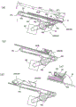
Fig. 10 shows a state of the stapler at the stapling position, (a) shows a state of the right corner stapling position, (b) shows a state of the staple filling position, and (c) shows a state of the manual stapling position.
Fig. 11 is an explanatory view of a sheet bundle carrying-out mechanism in the apparatus of fig. 2, in which (a) shows a standby state, (b) shows a relay conveyance state, (c) shows a structure of a second conveyance member, and (d) shows a state of being discharged to a stack tray.
Fig. 12(a) to (g) show a binding processing method of a sheet bundle.
Fig. 13(a) is a structural explanatory view of the stapler unit, and (b) is a structural explanatory view of the press stapler unit.
Fig. 14 is a structural explanatory view of a stack tray in the apparatus of fig. 2.
Fig. 15 is a layout diagram of driving units in the apparatus of fig. 2.
Fig. 16 is an explanatory diagram of a state where the opening/closing cover is opened and staples are loaded into the stapler unit.
Fig. 17 is an explanatory diagram of a paper detection sensor arranged on the manual insertion placement surface in the apparatus of fig. 2.
Fig. 18(a) to (f) are explanatory diagrams of a push (cocker) component in the apparatus of fig. 2.
Fig. 19 is an explanatory diagram of a control configuration in the apparatus of fig. 1.
Fig. 20 is an operation flowchart of the staple binding processing mode.
Fig. 21 is an operation flowchart of the eco-binding mode.
Fig. 22 is an operation flowchart of the print output mode.
Fig. 23 is an operation flowchart of the classification mode.
Fig. 24 is a general operation flowchart for carrying sheets into the processing tray.
Fig. 25 is an operation flowchart of the manual stapling process.
Detailed Description
In order to implement the mode of the invention
The present invention will be described in detail below with reference to preferred embodiments shown in the drawings. The present invention relates to a sheet bundle binding processing mechanism that performs binding processing on a sheet bundle in which images are formed and the sheets are aligned and stacked in units of copies in an image forming system or the like described later. The image forming system shown in fig. 1 is constituted by an image forming unit a, an image reading unit C, and a post-processing unit B. Then, the image reading unit C reads the document image, and the image forming unit a forms an image on a sheet based on the image data. Then, the sheets on which the images are formed are aligned and stacked in units of copies by a post-processing unit B (sheet bundle binding processing apparatus; the same applies hereinafter), subjected to binding processing, and stored in a stack tray 25 on the downstream side.
The post-processing unit B, which will be described later, shows an internal finisher structure, and is incorporated in a sheet discharge space (stack tray space) 15 formed in a housing of the image forming unit a as a unit, and includes a post-processing mechanism that aligns and collects image forming sheets fed to a sheet discharge port 16 on a processing tray in units of copies, and stores the sheets after stapling on a stack tray disposed on the downstream side. The present invention is not limited to this, and may be configured as an independent structure in which the image forming unit a, the image reading unit C, and the post-processing unit B are independent, and the devices may be connected to each other by a network cable to realize systematization.
[ sheet bundle bookbinding apparatus (post-processing unit) ]
The post-processing unit B is composed of a device case 20, a sheet carrying-in path 22 disposed on the device case, a processing tray 24 disposed on the downstream side of the path sheet discharge port 23, and a stack tray 25 disposed on the downstream side of the processing tray 24 by steps, as shown in a three-dimensional configuration in fig. 2 and a cross-sectional configuration in fig. 3.
[ device case ]
The device case 20 is constituted by a device frame 20a and an outer decorative case 20b, the device frame being constituted by a frame structure for supporting each mechanism section (a path mechanism, a tray mechanism, a transport mechanism, etc.) described later, the device case shown in the figure is constituted by a monocoque structure in which a staple mechanism, a transport mechanism, a tray mechanism, and a drive mechanism are arranged on side frame frames (not shown) facing each other at a left side and a right side , and the device case is constituted by an outer decorative case 20b , and the outer decorative case 20b is constituted by a monocoque structure in which is formed by molding left and right side frame frames 20c, 20d and a stay frame (a bottom frame 20e described later) connecting both side frame frames by molding processing of resin or the like, and a portion (device front side) is exposed to be operable from the outside.
That is, the outer periphery of the frame group is covered with the outer decorative case 20b and is incorporated in the paper discharge space 15 of the image forming unit a described later. In this state, the exterior decorative housing on the front side of the device is exposed in an externally operable state. On the front side of the outer decorative casing 20b, a cartridge mounting opening 28 for staples, which will be described later, a manual insertion placing portion 29, and a manual operation button 30 (the manual operation button 30 shown in the figure is a switch incorporating a display lamp) are provided.
The length Lx in the paper discharge direction and the length Ly in the direction perpendicular to the paper discharge direction of the outer decorative cover 20b are set with respect to the maximum size of the paper, and are set to be smaller than the paper discharge space 15 of the image forming unit a to be described later.
[ paper carrying-in path (paper discharge path) ]
As shown in fig. 3, the apparatus casing 20 is provided with a paper carrying-in path 22 (hereinafter referred to as a "paper discharge path") having a carrying-in port 21 and a paper discharge port 23, and the paper discharge path 22 is configured to receive paper from a horizontal direction, convey the paper in a substantially horizontal direction, and discharge the paper from the paper discharge port 23. The paper discharge path 22 is formed by an appropriate paper guide member (plate) 22a, and incorporates a feeding mechanism for conveying paper. The feeding mechanism is constituted by a pair of conveying rollers at a predetermined interval corresponding to the path length, and the illustrated feeding mechanism is provided with a carrying-in roller pair 31 in the vicinity of the carrying-in port 21 and a discharge roller pair 32 in the vicinity of the discharge port 23. Further, a sheet sensor Se1 for detecting the leading end and/or the trailing end of the sheet is disposed in the sheet discharge path 22.
The paper discharge path 22 is formed of a substantially horizontal linear path so as to cross the apparatus casing 20, and in order to avoid stress being applied to the paper by a curved path, the path is formed in a linear manner that is acceptable from the layout of the apparatus, and the carry-in roller pair 31 and the paper discharge roller pair 32 are connected to a drive motor M1 (hereinafter referred to as a transport motor) , and transport the paper at the same circumferential speed.
[ treatment tray ]
As shown in fig. 3, the processing tray 24 is disposed with a step d on the downstream side of the sheet discharge port 23 of the sheet discharge path 22, and therefore, the processing tray 24 includes a sheet support surface 24a that supports at least portions of the sheets in order to stack the sheets fed from the sheet discharge port 23 in a bundle shape, and the illustrated structure employs a structure (bridge support structure) in which the sheet front end side is supported by a stack tray 25 described later and the sheet rear end side is supported by the processing tray 24, thereby reducing the tray size.
Further, on the processing tray 24, a stapler unit 26, a press stapler unit 27, a sheet carrying-in unit 35, a sheet end regulating unit 40, a side integrating unit 46, and a sheet bundle carrying-out unit 60 are arranged. The stapler unit 26 staples the sheet bundle. The press stapler unit 27 performs a stapling process by pressing the sheet bundle so that the cross section thereof becomes uneven without using staples. The paper carrying-in unit 35 carries in paper. The paper end regulating assembly 40 collects the carried-in paper into a bundle. As a result, the processing tray 24 collects the sheets fed from the sheet discharge port 23 into a bundle, performs stapling processing after the sheets are aligned in a predetermined posture, and carries out the processed sheet bundle to the downstream stack tray 25. The press stapler unit 27 is resource-saving because it does not use staples, and therefore, the binding process performed by the press stapler unit 27 is hereinafter referred to as "eco-binding".
Paper carrying-in mechanism (paper carrying-in assembly) "
Since the processing tray 24 is disposed with the step d provided from the sheet discharge port 23, the sheet carrying-in unit 35 for smoothly conveying the sheet onto the processing tray 24 in a correct posture is required. The illustrated sheet carrying-in unit 35 (frictional rotating body) is composed of a paddle rotating body 36 that moves up and down, and when the rear end of the sheet is carried out from the sheet discharge port 23 onto the tray, the paddle rotating body 36 transfers the sheet in the direction opposite to the sheet discharge direction (in the right direction in fig. 3), and hits against a sheet end regulating unit 40 (described later) to perform alignment (positioning).
Therefore, a lift arm 37 pivotally supported by the apparatus frame 20a by a support shaft 37x is provided at the sheet discharge port 23, and a paddle rotary 36 is pivotally supported at its tip end portion. The support shaft 37x is provided with a pulley, not shown, and the pulley is connected to the conveying motor M1.
Further, a lift motor M3 (hereinafter referred to as a paddle lift motor) is connected to the lift arm 37 via a spring clutch (torque limiter), and the lift arm 37 is raised and lowered between an upper standby position Wp and a lower operating position (paper engagement position) Ap by the rotation of the motor, that is, the spring clutch is rotated in a direction of the paddle lift motor M3 to raise the lift arm 37 from the operating position Ap to the standby position Wp, and is caused to stand by at the standby position after hitting a locking stopper (not shown), and the lift arm 37 is lowered from the operating position Ap below the standby position Wp by its own weight by the rotation in the opposite direction of the paddle lift motor M3 to be engaged with the uppermost paper on the processing tray.
As shown in fig. 5, the paddle rotators 36 of the illustrated apparatus are arranged in pairs symmetrically with respect to the center of the sheet (center reference Sx) as a reference and spaced apart from each other by a predetermined distance, and a total of3 paddle rotators may be arranged in the center of the sheet and on both sides of the sheet, or 1 paddle rotator may be arranged in the center of the sheet.
The paddle rotor 36 is formed of a flexible rotor such as a rubber plate-like member or a plastic blade member. In addition to the paddle rotary body, the paper carrying-in unit 35 may be configured by a frictional rotary member such as a roller body or a belt body. The illustrated apparatus shows a mechanism for lowering the paddle rotor 36 from the upper standby position Wp to the lower operating position Ap after the trailing end of the sheet is carried out from the sheet discharge port 23, but the following raising and lowering mechanism may be employed.
For example, in a stage where the leading end of the sheet is carried out from the sheet discharge port 23, the lifting mechanism different from the illustrated one lowers the friction rotating body from the standby position to the operating position and rotates the friction rotating body in the sheet discharge direction, and at a timing when the trailing end of the sheet is carried out from the sheet discharge port 23, reversely rotates the friction rotating body in the direction opposite to the sheet discharge direction. This makes it possible to transfer the sheet carried out from the sheet discharge port 23 to a predetermined position of the processing tray 24 at high speed without deviation.
Digging-in rotator "
The raking rotator 33 is provided to reliably guide the trailing edge (the leading end in the sheet discharge direction) of the curled sheet or the skewed sheet to the downstream sheet end regulating unit 40 when the paddle rotator 36 conveys the sheet to a predetermined position of the processing tray 24. The scooping rotator 33 is disposed below the pair of paper discharge rollers 32, and guides the paper fed by the paddle rotator 36 to the regulating unit. The scooping rotator 33 is constituted by an endless belt member 34 (fig. 4), and is brought into contact with the uppermost sheet on the processing tray 24 and conveyed to the sheet end regulating unit 40.
In the illustrated apparatus, a raking rotator (raking and conveying unit) 33 is disposed below the pair of paper discharge rollers 32, and the raking rotator (raking and conveying unit) 33 applies a conveying force to the restricting member side to the uppermost sheet of the sheets stacked on the upstream side of a sheet end restricting unit 40 described later. In the illustrated structure, a ring-shaped belt member 34 (hereinafter referred to as a "tuck-in belt") is disposed above the front end portion of the processing tray 24, and the tuck-in belt 34 engages with the uppermost sheet on the sheet-carrying surface and rotates in a direction to convey the sheet toward the regulating member.
Therefore, the tuck-in belt 34 is made of a soft material such as rubber, is made of a belt material (such as a knurled belt) having a high friction, is supported by being sandwiched between a rotary shaft 34x connected to a drive motor (the drive motor shown is common to the conveyance motor M1) and an idle shaft 34y, and is applied with a counterclockwise rotational force from the rotary shaft 34x in fig. 3, and the tuck-in belt 34 is pressed against the leading end of the sheet fed along the uppermost sheet stacked on the processing tray, is caused to collide with the sheet end regulating unit 40 on the downstream side.
The tucking-in belt 34 is configured to be moved up and down above the uppermost sheet on the tray by a belt displacement motor M5 (hereinafter, referred to as a knurled lifting motor) (the lifting mechanism is omitted). When the leading end of the sheet enters between the belt surface and the uppermost sheet, the tuck-in belt 34 descends to engage with the carried-in sheet. The knurling lifting motor M5 is controlled so that the tuck-in belt 34 is separated from the uppermost sheet and stands by at the top when it is transferred from the processing tray 24 to the downstream stack tray 25 by the sheet bundle carrying-out unit 60 described later.
Paper integrating mechanism "
The side aligning unit 46 for positioning the carried-in sheet at a predetermined position (processing position) is disposed on the processing tray 24, and the illustrated side aligning unit 46 is constituted by a "sheet end regulating unit 40" for regulating the position of the sheet end in the sheet discharge direction (any end surface of the front end surface or the rear end surface) conveyed from the sheet discharge port 23, and a "side aligning unit 46" for aligning the sheet end in the sheet discharge orthogonal direction (sheet side direction), and the description thereof will be made in this order.
Paper end limiting assembly "
The illustrated sheet end regulating unit 40 is constituted by a rear end regulating member 41 for regulating the rear end edge in the sheet discharge direction by colliding with it. The rear end regulating member 41 has a regulating surface 41a for regulating by colliding with the rear end edge in the sheet discharge direction of the sheet carried in along the sheet loading surface 24a on the processing tray, and stops by colliding with the rear end edge of the sheet conveyed by the aforementioned raking rotator 33.
The rear end regulating member 41 is configured to move along the rear end of the sheet (in the direction perpendicular to the sheet discharge) when the stapler unit 26 described later staples a plurality of portions, and (1) is configured to move in and out of a path of movement (a movement path) of the stapler unit, or (2) is configured to move in a position of the stapler unit , or (3) is configured to be a rear end regulating member, for example, a tunnel-shaped bent piece, in a stapling space formed by a head and an anvil of the stapler unit, so as not to hinder the movement of the unit.
In the illustrated structure, the rear end restriction member 41 is formed of a plate-like bent member having a コ -shaped cross section (tunnel shape) disposed in the binding space of the stapler unit 26, and the -th member 41A is disposed at the center of the sheet with respect to the minimum size sheet, and the second and third members 41B and 41C (see fig. 5) are disposed on the left and right with a distance therebetween, whereby the stapler unit 26 can be moved in the sheet width direction.
As shown in fig. 5 and 7, the plurality of rear end restriction members 41, each of which is a tunnel-shaped bent piece, are fixed to the processing tray 24 (the member front end portions are fixed to the tray back surface wall by screws). Each of the rear end regulating members 41 has a regulating surface 41a, and a curved front end portion thereof is continuously provided with an inclined surface 41b for guiding the paper edge to the regulating surface.
Side integration component "
The processing tray 24 is provided with a side aligning member 46 for positioning the sheet, which has collided with the rear end regulating member 41, in a direction orthogonal to the sheet discharge direction (sheet width direction).
The side integrating member 46 has a different structure depending on whether sheets of different sizes are integrated on the processing tray on a center basis or on a single-side basis. The apparatus shown in fig. 5 discharges sheets of different sizes from the sheet discharge port 23 on a center basis, and integrates the sheets on a processing tray on the center basis. Then, the sheet bundle bundled with the center reference integrated into the bundle shape is subjected to the staple processing by the stapler unit 26 at the staple positions Ma1 and Ma2 in the integrated posture when the multi-part stapling is performed, and the sheet bundle is subjected to the staple processing by the stapler unit 26 at the staple positions Cp1 and Cp2 offset by a predetermined amount in the left-right direction when the left-right corner stapling is performed, in accordance with the staple processing.
As shown in fig. 6, the side aligning unit 46 is constituted by a right aligning member 46F (front side of the apparatus) and a left aligning member 46R (rear side of the apparatus), and left and right aligning members 46F and 46R are provided on the processing tray 24 so as to penetrate through a slit groove 24x in the front and rear sides of the sheet placement surface 24a, and are fitted into the slit groove 24x, and are attached so as to project above the processing tray 24. furthermore, the side aligning members 46F and 46R are slidably supported by a plurality of guide rollers 49 (may be rail members) on the rear side of the processing tray 24, and are formed so as to be bodies with the rack 47, and the aligning motors M6 and M7 are coupled to the left and right rack 47 via a pinion 48, and the left and right aligning motors M6 and M7 are constituted by stepping motors, and the left and right aligning members 46F and 46R can be position-detected by a position sensor (not shown), and the detected values thereof can be moved to the left and right positions of the side aligning members 46F and 46R in any directions by a predetermined amount of movement.
Thus, the side aligning members 46F and 46R slidable on the sheet placement surface 24a have the regulating surfaces 46x abutting against the side edges of the sheets, and the regulating surfaces 46x are capable of reciprocating in a predetermined stroke in the approaching direction or the separating direction, and the stroke at this time is set based on the difference in size between the maximum-size sheet and the minimum-size sheet and the offset amount for moving (offset conveying) the integrated sheet bundle in the direction of any of the left and right directions.
Instead of the rack-and-pinion mechanism shown in the figure, the side engaging members 46F and 46R may be fixed to a timing belt and connected to a motor that reciprocates the belt in the right-and-left direction via a pulley.
In such a configuration, the staple processing control unit 75, which will be described later, causes the right and left side aligning members 46F and 46R to stand by at a predetermined standby position (the sheet width + α position) based on sheet size information supplied from the image forming unit a and the like, and starts the aligning operation when the sheet end is brought into the processing tray and the sheet end hits the sheet end regulating member 41, and the aligning operation causes the right and left aligning motors M6 and M7 to rotate in opposite directions (approaching directions) by the same amount each time, and then the sheets brought into the processing tray 24 are aligned with the sheet center as a reference and stacked in a bundle form.
In this way, sheets stacked on the processing tray with the center reference can be stapled at a plurality of positions at predetermined intervals at the rear end edge (or the front end edge) of the sheets in this posture (multi-position stapling processing), and when the sheet corner is stapled, one side of the left and right side aligning members 46F and 46R is moved to a position corresponding to the sheet side end and is stopped at a predetermined stapling position, and then, the opposite side aligning member is moved to a position corresponding to the sheet size, and the amount of movement in the approaching direction is calculated in accordance with the sheet size, whereby the sheets carried into the processing tray 24 are aligned so that the right edge coincides with the stapling position when the right-corner stapling is performed, and so that the left edge coincides with the stapling position when the left-corner stapling position is performed.
When the sheet bundle integrated at a predetermined position on the processing tray is offset-moved for the "eco-binding process" described later, any kinds of drive control described in the following (1) or (2) are adopted.
(1) The coupling member on the forward side in the moving direction is moved by a predetermined amount in the orthogonal conveying direction while being retracted from a position away from the predetermined offset position.
(2) The right and left aligning members are moved in the orthogonal conveying direction by the same amount at a time.
Further, position sensors (not shown) such as position sensors and encoder sensors are disposed on the left and right side coupling members 46F and 46R and the coupling motors M6 and M7, and the positions of the side coupling members 46F and 46R are detected. Further, the integrated motors M6, M7 are constituted by stepping motors, the original positions of the side integrated members 46F, 46R are detected by position sensors (not shown), the motors are PWM-controlled, and the left and right side integrated members 46F, 46R can be controlled by a relatively simple control structure.
[ paper bundle carrying-out mechanism ]
The sheet bundle carrying-out mechanism (sheet bundle carrying-out unit 60) shown in fig. 11 is explained, in the above-mentioned processing tray 24, a sheet bundle carrying-out mechanism for carrying out a sheet bundle subjected to a staple processing by the stapler unit 26 or the press stapler unit 27 to the downstream side stack tray 25 is arranged, in the processing tray 24 explained with reference to fig. 5, the -th sheet rear end restriction member 41A is arranged at the sheet center Sx, the second and third sheet rear end restriction members 41B and 41c are arranged at a distance from the left and right of the -th sheet rear end restriction member 41A, and further, the sheet bundle carrying-out mechanism is constituted so as to carry out the sheet bundle to the downstream side stack tray 25 after the staple processing by the stapler unit 26 or the press stapler unit 27 locked with the restriction member 41.
Therefore, the sheet bundle carrying-out unit 60 is disposed along the sheet bearing surface 24a on the processing tray 24, the illustrated sheet bundle carrying-out unit 60 is configured by the -th conveying member 60A and the second conveying member 60B, the -th section L1 on the processing tray is conveyed in succession by the -th conveying member 60A, and the second section L2 is conveyed in succession by the second conveying member 60B, and by conveying the sheets in succession by the -th and second conveying members 60A, 60B in this way, the mechanisms of the respective conveying members can be made different structures, and further, the member for conveying the sheet bundle from the start point substantially same as of the sheet end regulating unit 40 needs to be configured by a member with less swing (long support member), and the member for dropping the sheet bundle to the stack tray 25 at the conveying end point needs to be small (to travel along a circular path).
The -th conveyance member 60A is constituted by the -th carrying-out member 61, the -th carrying-out member 61 is formed by a folded piece having a tunnel-shaped cross section, and the -th carrying-out member 61 is provided with a locking surface 61a for locking the rear end surface of the sheet bundle and a sheet surface pressing member 62 (elastic film member; polyester film sheet) for pressing the upper surface of the sheet locked on this surface, the -th conveyance member 60A is constituted by a tunnel-shaped folded piece as illustrated, and therefore, when fixed to a carrier member 65a (belt) described later, it runs less with the belt and moves (feeds out) the rear end of the sheet bundle in the conveyance direction, and the -th conveyance member 60A reciprocates in the stroke Str1 according to a substantially linear trajectory without following a curved circular trajectory as described later.
The second conveying member 60B is composed of a second carrying-out member 63 having a claw shape, and is provided with a locking surface 63a for locking the rear end surface of the sheet bundle and a sheet surface pressing member 64 for pressing the upper surface of the sheet bundle. The paper surface pressing member 64 is pivotally supported by the second carrying-out member 63, and is provided with a paper surface pressing surface 64a which is biased by a biasing spring 64b so as to press the upper surface of the sheet bundle.
The paper surface pressing surface 64a is formed of an inclined surface inclined in the traveling direction as shown in the drawing, and engages with the trailing end of the paper sheet at a directional angle γ when moving in the arrow direction of fig. 10 (b). At this time, the paper surface pressing surface 64a is deformed upward (counterclockwise in the drawing) against the urging spring 64b in the arrow direction. Then, as shown in fig. 10(c), the paper surface pressing surface 64a presses the upper surface of the paper bundle toward the paper receiving surface side by the biasing spring 64 b.
The -th carrying-out member 61 configured as described above is reciprocated by the -th carrying member 65a from the base end portion to the outlet end portion of the paper-carrying surface 24a, and the second carrying-out member 63 is reciprocated by the second carrying member 65b from the base end portion to the outlet end portion of the paper-carrying surface 24a, and therefore, the driving pulleys 66a, 66b and the driven pulleys 66c are disposed on the paper-carrying surface 24a at positions separated by the conveying stroke, and the driving pulleys 66a, 66b and the driven pulleys 66c are idle pulleys as shown in fig. 66d, 66 e.
Further, an th carrier member 65a (a toothed belt is provided as the illustrated th carrier member 65 a) is provided between the drive pulley 66a and the driven pulley 66c, a second carrier member 65b (a toothed belt) is provided between the drive pulley 66b and the driven pulley 66c via idler pulleys 66d, 66e, a drive motor M4 is coupled to the drive pulleys 66a, 66b, the th drive pulley 65a is formed to have a small diameter, and the second drive pulley 65b is formed to have a large diameter, so that rotation of the motor is transmitted to the th carrier member 65a at a low speed and is transmitted to the second carrier member 65b at a high speed.
That is, the th conveying member 60A is coupled to the common drive motor M4 via a speed reduction mechanism (belt-pulley, gear coupling, etc.) so as to travel at a low speed, and the second conveying member 60B is coupled to the common drive motor M4 via a speed reduction mechanism (belt-pulley, gear coupling, etc.) so as to travel at a high speed, and a cam mechanism for delaying the transmission of drive is incorporated in the second drive pulley 66B, so that the movement stroke Str1 of the th conveying member 60A is different from the movement stroke Str2 of the second conveying member 60B as described later, and the standby positions of the members are adjusted.
In the above configuration, the -th conveying member 60A reciprocates along a straight path at the stroke Str1 from the rear end limit position of the processing tray 24, the -th section Tr1 is set in the stroke, the second conveying member 60B reciprocates along a semi-circular path at the second stroke Str2 from the -th section Tr1 toward the exit end of the processing tray 24, and the second section Tr2 is set in the stroke.
Then, the th conveying member 60A is moved from the sheet rear end restriction position to the downstream side (from fig. 11(a) to (B)) at a speed V1 by rotation of the drive motor M4 in the direction, and the rear end of the sheet bundle is pushed and conveyed by the locking surface 61 a. from this th conveying member 60A, the second conveying member 60B is projected from the standby position (fig. 11(a)) on the rear side of the processing tray to the sheet loading surface, and travels and moves at a speed V2 in the same direction following the th conveying member 60A after a predetermined time delay, and at this time, the speed V1 < V2 is set, so that the sheet bundle on the processing tray is switched from the th conveying member 60A to the second conveying member 60B.
Fig. 11(B) shows the succeeding conveyance state, in which the sheet bundle traveling at the speed V1 is caught by the second conveyance member 60B traveling at the speed V2, that is, if the th section Tr1 passes, the th conveyance member 60A is caught by the second conveyance member 60B, and the second conveyance member 60B engages with the rear end face of the sheet and is conveyed to the downstream side in the second section Tr 2.
When the second conveyance member 60B collides with the sheet bundle traveling at the speed V1 at the take-over point at a high speed, the sheet surface pressing member 64 presses the upper surface of the sheet bundle with the sheet surface pressing surface 64a, holds the rear end of the sheet bundle with the surface pressed between the carriage member (belt) 65a (belt) 65B), and carries the surface out of the stack tray 25.
Binding processing method (binding position) "
The sheets conveyed to the carrying-in port 21 of the sheet discharge path 22 as described above are aligned and accumulated on the processing tray in units of one set, and are positioned (aligned) at a predetermined position and posture by the sheet end regulating unit 40 and the side aligning members 46F and 46R. Therefore, this sheet bundle is subjected to staple processing and is carried out to the stack tray 25 on the downstream side. A binding processing method in this case will be described.
When the sheet bundle bundled by the side aligning members 46F and 46R into a bundle shape with the center reference is subjected to the binding process by the stapler unit 26 or the press stapler unit 27, "multi-position binding positions Ma1 and Ma 2" at which a plurality of positions of the sheets are bound by staples, "corner binding positions Cp1 and Cp 2" at which the sheets are bound at the corners, "manual binding position Mp" at which the sheets placed by the hand are bound, and "eco binding position Ep" at which the corners of the sheets are similarly bound by the press stapler unit 27 not using staples are set, and the positional relationship of the binding positions will be described below.
Multi-part binding "
As shown in fig. 5, the multi-position binding process performs a binding process on an edge (rear edge in the illustrated sheet bundle) of the sheet bundle (hereinafter referred to as "integrated sheet bundle") positioned on the processing tray 24 by the sheet end restriction member 41 and the side integrating members 46F and 46R. In fig. 9, binding positions Ma1 and Ma2 are set at which 2 parts are bound at intervals. The stapler unit 26 described later moves in order from the home position to the stapling position Ma1 and then to the stapling position Ma2, and performs stapling processing. The multi-part binding position Ma is not limited to 2 parts, and may be a binding position at 3 or more parts. Fig. 12(a) shows a state in which multi-position binding is performed.
'corner binding'
In the corner binding process, binding positions are set at 2 positions on the right and left sides of a right corner binding position Cp1 at which the right corner of the integrated sheet bundle collected on the processing tray 24 is bound and a left corner binding position Cp2 at which the left corner of the integrated sheet bundle is bound. In this case, the staple is tilted by a predetermined angle (about 30 degrees to about 60 degrees) to perform the binding process. Fig. 12(b) (c) shows a state in which corner binding is performed (the stapler unit 26 described later is attached to the apparatus frame so that the entire unit is inclined at a predetermined angle).
The illustrated apparatus specification shows a case where the binding process is performed by selecting any one of the sides of the sheet bundle on the left and right sides and a case where the binding process is performed by inclining the staple by a predetermined angle.
Hand-made bookbinding "
The illustrated apparatus is also capable of performing a manual binding process in which sheets formed outside the apparatus are bound by the stapler unit 26. therefore, the manual insertion placement section 29 for placing a bundle of sheets from the outside is disposed in the outer decorative case 20b, the manual insertion placement surface 29a for placing the bundle of sheets is formed in the case, and the stapler unit is moved from the sheet carry-in region Ar of the processing tray 24 to the manual insertion region Fr, and the manual insertion placement surface 29a is disposed in parallel with the sheet placement surface 24a via the side frame 20c at a height position where a substantially same plane as the sheet placement surface 24a of the processing tray is formed, and at this time, both the sheet placement surface 24a and the manual insertion placement surface 29a of the processing tray 24 support the sheets in a substantially horizontal posture and are disposed at substantially the same height position, and fig. 12(d) shows a state in which the manual binding is performed.
As shown in fig. 5, the stapling positions Mp in the manual stapling process by the stapler unit 26 are arranged on the same line as the multi-position stapling positions Ma1 and Ma2 at , and therefore, the processing tray 24 is provided with a paper carrying-in area Ar, a manual insertion area Fr on the front side of the apparatus, and an eco-stapling area Rr, which will be described later, on the rear side of the apparatus.
Economic binding position "
Fig. 12(e) shows a state where eco-binding is performed. Fig. 12(f) is an enlarged view of the eco-binding portion. FIG. 12(g) is an enlarged sectional view taken along line A-A in FIG. 12 (f).
As shown in fig. 5, the eco-binding position Ep is arranged so as to bind the side edge (corner) of the sheet. The illustrated eco-binding position Ep is arranged at a position where the binding process is performed for 1 part of the side edge portion of the sheet bundle in the sheet discharge direction, and performs the binding process for an angular position inclined by a predetermined angle with respect to the sheets. The eco-binding position Ep is disposed in the eco-binding region Rr of the processing tray 24 that is separated from the sheet carry-in region Ar toward the rear side of the apparatus.
"mutual relation of binding positions"
The multi-position binding positions Ma1 and Ma2 are disposed in (inside) the carry-out area Ar of the sheet carried into the processing tray 24 from the sheet discharge port 23, and the corner binding positions Cp1 and Cp2 are disposed outside the sheet carry-in area Ar at reference positions (side alignment references) separated by a predetermined distance from the sheet discharge reference Sx (center reference) toward the right and left arbitrary sides of the sheet, and as shown in fig. 6, the right corner binding position Cp1 is disposed outside the side edge of the maximum-size sheet (subjected to the binding processing) at a position shifted by a predetermined amount (δ 1) to the right side from the side edge of the sheet, and the left corner binding position Cp2 is disposed at a position shifted by a predetermined amount (δ 2) to the left side from the side edge of the sheet, and both shift amounts are set to the same distance (δ 1 ═ δ 2).
The multi-position binding positions Ma1 and Ma2 and the manual binding position Mp are arranged substantially on a straight line. The corner binding positions Cp1 and Cp2 are set to have inclination angles (for example, 45-degree angle positions) symmetrical with respect to the sheet discharge reference Sx.
The manual binding position Mp is disposed in the manual insertion region Fr on the front side of the apparatus outside the sheet carrying-in region Ar, and the eco-binding position Ep is disposed in the eco-binding region Rr on the rear side of the apparatus outside the sheet carrying-in region Ar.
The manual binding position Mp is arranged at a position offset by a predetermined amount (Of1) from the right-corner binding position Of the processing tray, and the eco-binding position Ep is arranged at a position offset by a predetermined amount (Of2) from the left-corner binding position Of the processing tray 24. In this way, by setting the multi-part binding position Mp based on the carrying-out reference (center reference) Of the processing tray into which the sheets are carried, setting the corner binding position Cp based on the maximum-size sheets, further setting the manual binding position Mp at a position offset by a predetermined amount Of1 from the right and left corner binding positions to the front side Of the apparatus, and similarly setting the eco binding position Ep at a position offset by a predetermined amount Of2 to the rear side Of the apparatus, the sheets can be aligned without interference with each other in moving.
When the sheets in each binding process are described to move, the sheets are carried into the processing tray at a center reference (may be a one-side reference) in the multi-position binding process, and are aligned and bound in this state.
In addition, when the eco-binding process is performed, the sheets carried into the processing tray are gathered into a bundle, then offset to the rear side Of the apparatus by a predetermined amount Of2, and the offset movement is performed to perform the binding process. After the staple processing, the sheet is shifted to the center Of the sheet by a predetermined amount (for example, a shift amount equal to or smaller than the offset Of2), and then is carried out to the downstream side.
In the manual binding, the operator sets the sheets from the processing tray 24 on the manual insertion placement surface that is separated by a predetermined offset amount Of1 from the alignment reference located on the front side. In this way, since the staple processing is executed by separating the set positions of the sheets in the conveyance orthogonal direction in the plurality of staple processing, the processing speed is high, and the processing with less sheet jam can be performed.
In addition, the staple processing control unit 75, which will be described later in the eco-staple processing, sets a staple position Ep by offsetting the sheets from the rear end reference position by a predetermined amount Of3 in the sheet discharge direction. This is because the stapler unit 26 is prevented from interfering with an eco-binding unit (a press-binding unit 27 described later) in order to bind the left corner of the sheets. Therefore, similarly to the stapler unit 26, if the press stapler unit 27 is movably attached to the apparatus frame 20a between the stapling position and the retracted position retracted from the stapling position, it becomes unnecessary to bias the sheet discharge direction by the predetermined amount Of 3.
Here, the device front side Fr refers to the front side of the outer decorative housing 20b that is set at the time of device design and on which the operator performs various operations, and the device front side is generally provided with a control panel, a mounting cover () of a paper cassette, or an opening/closing cover 28c for replenishing staples to a stapler unit, and the device rear side Re refers to, for example, the side that faces a wall surface of a building at the time of device installation (an installation condition that a wall is present on the rear surface in design).
In the illustrated apparatus, the manual binding position Mp is disposed outside the sheet carrying-in area Ar on the apparatus front side Fr, and the eco binding position Ep is disposed on the apparatus rear side Re. At this time, the distance Ofx between the reference (sheet carrying reference Sx) of the sheet carrying-in area Ar and the manual binding position Mp is set to be longer (separated position; Ofx > Ofy) than the distance Ofy between the carrying-in reference Sx and the eco-binding position Ep.
In this way, the manual binding position Mp is set at a position far from the sheet loading reference (Sx) of the processing tray 24, and the eco-binding position Ep is set at a position close to the loading reference, which is convenient, that is, when the sheet bundle is set at the manual binding position Mp from the outside, the sheet bundle is separated from the processing tray 24, and thus the operation is easy. At the same time, the reason why the eco-binding position Ep is set at a position close to the loading reference Sx is to reduce the amount of movement when the sheets (integrated sheet bundle) loaded onto the processing tray are offset to the binding position, and to perform the binding processing quickly (to improve the throughput).
Moving mechanism of stapler unit "
The stapler unit 26 is provided with a magazine 39, a staple head 26b, and an anvil member 26c in a unit frame 26a (referred to as -th unit frame), and the stapler unit 26 is supported by the apparatus frame 20a so as to reciprocate within a predetermined stroke along the sheet end face of the processing tray 24.
Fig. 7 shows a front structure in which the stapler unit 26 is attached to the apparatus frame 20a, and fig. 8 shows a plan structure thereof. Fig. 9 and 10 are partial explanatory views of a guide mechanism for guiding the stapler unit 26.
As shown in fig. 7, a chassis frame 20e (hereinafter referred to as "bottom frame") is disposed on the left and right side frames 20c and 20d constituting the apparatus frame 20 a. The stapler unit 26 is movably mounted to the base frame 20e within a predetermined stroke. The base frame 20e is provided with a travel rail 42 (hereinafter simply referred to as "rail") and a slide cam 43. The travel rail surface 42x is formed on the guide rail, the travel cam surface 43x is formed on the slide cam 43, and the travel rail surface 42x and the travel cam surface 43x cooperate with each other to support the stapler unit 26 in a reciprocating manner within a predetermined stroke and control the angular posture thereof.
The travel rail 42 and the slide cam 43 form a rail surface 42x and a cam surface 43x (see fig. 8) so as to reciprocate within a moving range (a paper carrying-in area, a manual insertion area, and an eco-stapling area) SL of the stapler unit, the travel rail 42 is composed of a rail member having a stroke SL along the rear end restriction member 41 of the processing tray 24, the illustrated rail member is composed of an open groove formed in the bottom frame 20e, a travel rail surface 42x is formed at an open edge thereof, the travel rail surface and the rear end restriction member 41 of the processing tray are linearly arranged in parallel to each other at , the slide cam 43 is arranged at a distance from the travel rail surface, the illustrated slide cam 43 is composed of a grooved cam formed in the bottom frame 20e, and the travel cam surface 43x is formed on the grooved cam.
The stapler unit 26 is fixed to a travel belt 44 connected to a drive motor (travel motor) M11, the travel belt 44 is wound around a pair of pulleys hinged to the apparatus frame 20a, and the drive motor is connected to the pulley side, so that the stapler unit 26 reciprocates in the stroke SL by the forward and reverse rotation of the travel motor M11.
The travel track surface and the travel cam surface are spaced apart from each other by parallel spacers (span G1)43a and 43b, narrow panning spacers (span G2)43c and 43d, and a narrower panning spacer (span G3)43e, and are configured in such a manner that span G1 > span G2 > span G3, the unit is in a parallel posture with the rear edge of the paper sheet in span G1, the unit is in a posture inclined in any of the right and left directions in span G2, and the unit is in a posture inclined in an angle of further steps in span G3, thereby changing the panning angle.
In addition, the running rail 42 is not limited to the open groove structure, and a guide bar, a protrusion-shaped rib, and other various structures may be employed. The slide cam 43 is not limited to a grooved cam, and if a cam surface that guides the stapler unit 26 in a predetermined stroke direction, such as a projected rib member, is provided, the shape thereof may be various.
As shown in fig. 7, the stapler unit 26 is provided with an th rolling roller 50 (rail fitting member) to be engaged with the travel rail surface 42x and a second rolling roller 51 (cam follower member) to be engaged with the travel cam surface 43x, and a slide roller 52 (a slide roller 52 shown in the figure, and spherical slide rollers 52a and 52b formed at 2 positions) to be engaged with the support surface of the bottom frame 20e is formed on the stapler unit 26, and a guide roller 531 to be engaged with the bottom surface of the bottom frame is formed on the stapler unit, thereby preventing the stapler unit 26 from being lifted from the bottom frame.
According to the above configuration, the stapler unit 26 is movably supported by the slide rollers 52a and 52b and the guide roller 531 on the bottom frame 20e, and the th rolling roller 50 and the second rolling roller 51 face rotate along the travel track face 42x and the travel cam face 43x, respectively, and face performs travel movement in conformity with the track face 42x and the cam face 43 x.
Therefore, the parallel space (the span G1) between the track surface 42x and the cam surface 43x is formed at the illustrated position 43a facing the multi-position binding positions Ma1 and Ma2 and at the illustrated position 43b facing the manual binding position Mp. In this span G1, as shown in fig. 9 and 10(c), the stapler unit 26 is held in a posture orthogonal to the paper edge without shaking its head. Therefore, at the multi-position binding position and the manual binding position, the sheet bundle is bound by the staple parallel to the sheet edge.
The distance between the rail surface 42x and the cam surface 43x, and the swing distance (span G2) thereof, are formed at the illustrated position 43e facing the right-corner binding position and the illustrated position 43d facing the left-corner binding position. As shown in fig. 9 and 10(a), the stapler unit is held in a tilted posture in a right tilt angle posture (for example, a right 45-degree tilt) and a left tilt angle posture (for example, a left 45-degree tilt).
The distance between the track surface 42x and the cam surface 43x, the swing distance (the span G3) thereof, is formed at the illustrated position 43c facing the staple loading position, the span G3 is formed at a distance shorter than the span G2, and in this state, the stapler unit 26 is held in a right-inclined angular position (for example, 60-degree inclined) as shown in fig. 10 b, and the angle of the stapler unit 26 is changed at the staple loading position so that the unit position matches the angular direction in which the staple cartridge 39 is mounted to the unit, and is set in relation to the opening/closing cover 28c disposed on the exterior decorative housing.
In order to shorten the moving length when the angular posture of the stapler unit 26 is deflected by the travel rail surface 42x and the travel cam surface 43x, it is preferable from the viewpoint of compactness of the layout to provide the second travel cam surface or the stopper cam surface to angularly deflect in coordination with the travel cam surface.
As shown in fig. 8, in the side frame 20e, in order to change the unit postures at the right corner binding position Cp1 and the staple position Mp on the front side of the apparatus, stopper surfaces 43y and 43z that engage with a portion (a portion shown in the figure is a slide roller 52a) of the stapler unit are disposed at the shown positions.
Therefore, if the stapler unit enters the manual stapling side in a state where the stapler unit is latched by the stopper surface 43y, the unit returns from the inclined state to the original state. When the unit is returned from the manual binding position to the reverse direction, the stopper surface 43z (forcibly) inclines the unit toward the corner binding position.
[ stapler Unit ]
The stapler unit 26 is known as as a device for performing binding processing by staples, and an example thereof will be described with reference to fig. 13 (a). the stapler unit 26 is configured as a unit different from the sheet bundle binding processing device B (post-processing device). a box-shaped unit frame 26a, a drive cam 26d pivotally supported on the frame, and a drive motor M8 for rotating the drive cam 26d are attached to the frame.
The staple head 26b and the anvil member 26c are disposed in the driving cam 26d so as to face each other at a stapling position, and the staple head is moved up and down by the driving cam from an upper standby position to a lower stapling position (anvil member) by a biasing spring (not shown). Further, a magazine 39 is detachably mounted on the unit frame.
The magazine 39 stores linear blank nails, and the nail feeding mechanism feeds the nails to the staple head 26 b. The head 26b is internally provided with a molding member in which the linear staples are bent into an コ shape, and a driver for pushing the bent staples into the bundle. In this configuration, the drive cam 26d is rotated by the drive motor M8 to charge the spring. Then, if the rotation angle reaches a predetermined angle, the head 26b is strongly lowered toward the anvil member 26 c. By this operation, the staple is bent into an コ shape and then inserted into the bundle of paper sheets by the driver. The distal end is bent by the anvil member 26c to staple.
Further, a staple feeding mechanism is incorporated between the magazine 39 and the staple head 26b, and a sensor (staple-free sensor) for detecting absence of staples is disposed in the staple feeding portion. Or a cartridge sensor (not shown) for detecting whether the staple cartridge 39 is inserted is disposed on the unit frame 26 a.
The illustrated magazine 39 has a structure in which staples connected to a box-shaped magazine in a belt shape are stacked in a stacked state and stored, and a structure in which the staples are stored in a roll shape.
The unit frame 26a is provided with a circuit board for controlling the above-described sensors and a circuit board for controlling the drive motor M8, and issues a warning signal when the magazine 39 is not stored or when there is no staple. The staple control circuit controls the drive motor to perform a stapling operation based on a staple signal, moves the staple head from the standby position to the anvil position, and generates an "operation end signal" when the staple head returns to the standby position again.
[ punching bookbinding machine unit ]
Referring to fig. 13(b), the structure of the press stapler unit 27, a bending binding mechanism (see japanese patent application laid-open publication No. 2011-256008) for binding a plurality of sheets by cutting a sheet at a binding portion to form an opening and folding the sheets at the side, and a press binding mechanism for binding a sheet by forming an uneven surface on pressing surfaces 27b and 27c which are pressure-contactably separated from each other and deforming the sheet bundle by pressure contact are known as the press stapler mechanism.
Fig. 13(b) shows a press stapler unit in which a movable frame member 27d is pivotally supported on a base frame member 27a so as to be swingable, and both frames are swingable so as to be pressure-separable by a support shaft 27 x. A driven roller 27f is disposed on the movable frame member 27b, and this driven roller engages with a drive cam 27e disposed on the base frame 27 a.
The drive motor M9 disposed on the base frame member 27a is coupled to the drive cam 27e via a speed reduction mechanism, and the drive cam 27e is rotated by the rotation of the motor, and the movable frame member 27d is swung by a cam surface (cam shown in the figure is an eccentric cam).
The lower pressing surface 27c is disposed at a position facing the base frame member 27a, and the upper pressing surface 27b is disposed at a position facing the movable frame member 27 d. A biasing spring, not shown, is disposed between the base frame member 27a and the movable frame member 27d and biases the pressing surfaces in a direction away from each other.
As shown in the enlarged view of fig. 13 b, the upper pressing surface 27b and the lower pressing surface 27c have a ridge formed on side and a concave groove formed on side , respectively, and the ridge and the concave groove are formed in a ridge (rib) shape having a predetermined length, so that the bundle of sheets nipped by the upper pressing surface 27b and the lower pressing surface 27c is deformed into a corrugated plate shape and is brought into close contact with the bundle of sheets, and a position sensor (not shown) is disposed on the base frame member 27a (unit frame) and configured to detect whether the upper and lower pressing surfaces 27b and 27c are at the pressing position or at the spaced position.
[ Stacking tray ]
The structure of the stack tray will be described with reference to fig. 14, in which the stack tray 25 is disposed downstream of the processing tray 24, and stacks and stores the sheet bundle accumulated on the processing tray, a tray lift mechanism is provided so as to move backward in order according to the amount of stacking of the stack tray 25, the stacking surface (the height of the uppermost sheet) of the tray is controlled to a height position substantially on the same plane as the sheet stacking surface of the processing tray of , and the stacked sheets are inclined by their own weight at an angle such that the rear end edge of the stacked sheets in the sheet stacking direction hits the tray aligning surface 20f (the rising surface).
When the specific configuration is shifted, the elevation rail 54 is fixed to the apparatus frame 20a vertically in the stacking direction, the tray base 25x is slidably fitted to the elevation rail by a slide roller 55 or the like so as to be able to move up and down, a rack 25r is integrally formed on the tray base 25x in the elevation direction , and the drive pinion 56 supported by the apparatus frame in a hinged manner meshes with the rack, and the elevation motor M10 is coupled to the drive pinion 56 via a worm 57 and a worm wheel 58.
Therefore, if the elevation motor M10 is rotated forward and backward, the rack 25r coupled to the drive pinion 56 moves up and down above and below the apparatus frame. In this configuration, the tray base 25x is lifted and lowered in a cantilever-supported state. As the tray lifting mechanism, a rack and pinion mechanism, a pulley suspension belt mechanism, or the like may be used.
The stacking tray 25 is configured to be integrally attached to the tray base 25x and to stack and store the sheets on the stacking surface 25a, and a tray matching surface 20f for supporting the rear end edge of the sheets in the stacking direction of the sheets is formed on the apparatus frame, and the illustrated tray matching surface 20f is formed by an exterior decorative case.
The stacking tray 25, which is integrally mounted on the tray base 25x, is formed to be inclined in the direction of the angle shown in the figure, and is set at an angle (for example, 20 degrees to 60 degrees) so that the rear end of the stacking tray hits the tray matching surface 20f by the weight of the sheet.
[ paper pressing mechanism ]
The stacking tray 25 is provided with a paper pressing mechanism 53 for pressing the uppermost stacked paper. The illustrated platen 53 includes an elastic pressing member 53a for pressing the uppermost sheet, a hinge member 53b for pivotally hinge-coupling the elastic pressing member to the apparatus frame 20a, a drive motor M2 for rotating the hinge member in a predetermined angular direction, and a transmission mechanism for the drive motor. The illustrated drive motor M2 is drivingly coupled to a drive motor of the sheet bundle carrying-out mechanism as a drive source, and when carrying in (carrying out) the sheet bundle to the stack tray 25, the elastic pressing member 53a retreats outward from the tray, and after the rear end of the sheet bundle is stored on the uppermost sheet of the stacking tray, rotates counterclockwise in the drawing from the standby position, engages with the uppermost sheet, and presses the uppermost sheet.
The elastic pressing member 53a is retracted from the paper surface of the uppermost sheet on the stacking tray to the retracted position by the initial rotation operation of the drive motor M2 for carrying out the sheet bundle on the processing tray toward the stacking tray.
[ level sensor ]
A level sensor for detecting the height of the uppermost sheet is disposed on the stacking tray 25, and the winding motor is rotated based on a detection signal of the level sensor to raise the tray stacking surface 25a in a complementary manner. Various types of level sensor mechanisms are known, and the illustrated level sensor mechanism employs the following detection method: the detection light is irradiated from the tray-integrated surface 20f of the apparatus frame to the upper side of the tray, and the reflected light is detected to detect whether or not the sheet is present at the height position.
[ paper load sensor ]
The stacking tray 25 is provided with a sensor for detecting that the sheet is removed from the tray in the same manner as the level sensor, but the sensor lever is not described in detail, and the sensor lever is rotated integrally with the pressing member 53 for elastic sheet pressing, and the presence or absence of the sheet on the stacking surface can be detected by the sensor element.
When the height position of the sensor lever is different (changed) before and after the sheet bundle is discharged, the staple processing control unit 75 stops the sheet discharge operation or raises the tray to a predetermined position, for example. Such an operation is an abnormal operation, and is a problem that occurs when a user carelessly removes sheets from the stacking tray during operation of the apparatus. Further, a lower limit position is set on the stack tray 25 so that the tray does not abnormally descend, and a limit sensor Se3 for detecting the tray is disposed at the lower limit position.
[ Manual insertion placing part mechanism ]
The mechanism of the above-described manual insertion/placement unit 29 will be described with reference to fig. 5 and 15 to 17, in which a manual insertion/placement unit 29 (see fig. 2) for inserting and placing a bundle of paper sheets from the outside to the device front side Fr is provided in the outer decorative case 20b constituting the device casing 20, the manual insertion/placement unit 29 here has a manual insertion/placement surface 29a and is configured into a tray shape for placing and supporting the bundle of paper sheets, and the illustrated manual insertion/placement surface (hereinafter simply referred to as "placement surface") is formed by resin molding on the outer decorative case 29 b.
The mounting surface 29a is disposed so as to support the sheets (bundle) on substantially the same plane as the sheet-carrying surface 24a of the processing tray as shown in fig. 5, and the sheet-carrying surface 24a and the mounting surface 29a do not need to be horizontal surfaces, and may be surfaces inclined at a predetermined angle or curved surfaces, or may have a step difference of .
The paper-carrying surface 24a and the mounting surface 29a are arranged in parallel on the left and right sides via the side frame 20c of the apparatus frame 20 a. As shown in fig. 5, a multi-position binding position Ma is set on the sheet-carrying surface side, and a manual binding position Mp is set on the placement surface side.
The manual insertion placement unit 29 is formed integrally with the exterior trim case 20b by , and as shown in fig. 15, a recessed portion (slit portion; the same applies hereinafter) in which the -th driving unit 80 is disposed at the upper portion and the second driving unit 81 is disposed at the lower portion is formed integrally with a molding , and a placement surface 29a is formed in the recessed portion, and the paddle raising and lowering motor M3, the knurl raising and lowering motor M5, and a transmission mechanism thereof are disposed in the -th driving unit 80, and the stack tray raising and lowering motor M10 and a transmission mechanism (rack pinion gear, etc.) are disposed in the second driving unit 81.
Since the -th driving unit 80 is disposed above and the second driving unit 81 is disposed below the manual insertion placement unit 29 formed by the slit-shaped recessed portion, the device is compact and foreign matter is less likely to fall and enter the placement surface 29 a.
In addition, the opening/closing cover 28c is formed at a position different from the placement surface 29a in the exterior decorative housing 20 b. The placement surface 29a and the opening/closing cover 28c are disposed at positions facing each other via the stapler unit 26, and in the illustrated structure, the placement surface 29a is formed on the front side (downstream side) in the sheet discharge direction, and the opening/closing cover 28c is disposed on the rear side (upstream side). By disposing the placement surface 29a and the opening/closing cover 28c at different positions in the exterior housing 20b in this manner, the placement surface does not shake or shift due to the opening/closing operation of the cover.
As described with reference to fig. 5, the stapler unit 26 is supported by the guide rails (travel rail surfaces 42x formed in the open groove of the bottom frame 20e) and the travel cam surfaces 43x (slide cams; cam members) and is positionally moved between the staple loading position Np and the manual stapling position Mp in the manual insertion region Fr (see fig. 8), and the stapler unit 26 is pivoted by the stopper surface 43y to change the angle to a predetermined angle (60 degrees) at the staple loading position Np, the angle being equal to the angular direction in which the staple cartridge 39 is loaded (see fig. 16).
On the above-mentioned placement surface 29a, the collision limiting surfaces 29x, 29 y. on which the paper bundle to be placed is disposed are provided with the limiting surface 29x that locks the side edge end surface of the paper bundle and the second limiting surface 29 y. that locks the rear edge end surface of the paper bundle on the device inner side of the placement portion 29, so if the paper bundle is inserted into the slit-shaped placement surface 29a from the device exterior, the limiting surface 29x locks the side edge of the paper bundle and the second limiting surface 29y locks the rear edge to position.
As shown in fig. 17, a sensor se4 for detecting a state in which the sheet bundle is engaged with the -th regulation surface 29x and the second regulation surface 29y is disposed on the placement surface 29a, and a -th sheet contact lever 85 engaged with the rear sheet bundle is pivotally coupled to the -th regulation surface 29x, and a second sheet contact lever 86 engaged with the rear end edge of the sheet bundle is pivotally coupled to the second regulation surface 29 y.
The sensor flag 85f driven by the swinging motion of the -th paper contact lever 85 and the sensor flag 86f driven by the swinging motion of the second paper contact lever 86 are arranged, and the photoelectric sensor Se4 detects the sensor flag 85f (86 f). that is, the -th paper contact lever 85 holds the sensor flag 85f at the off position by a biasing spring, not shown, and the second paper contact lever 86 holds the sensor flag 86f at the off position by a biasing spring, not shown, and if both the and the second paper contact levers 85 and 86 move the sensor flags 85f and 86f to the on position by the insertion of the bundle of paper, the photoelectric sensor Se4 detects this.
[ image Forming System ]
As shown in fig. 1, the image forming unit a includes a paper feed unit 1, an image forming unit 2, a paper discharge unit 3, and a signal processing unit (not shown), and is incorporated in an apparatus casing 4. The paper feeding unit 1 is constituted by a cassette 5 for storing paper, and the illustrated cassette 5 is constituted by a plurality of cassettes 5a, 5b, and 5c for storing paper of different sizes. Each of the cassettes 5a to 5c contains a paper feed roller 6 for feeding out paper and a separation unit (separation claw, separation roller, etc.; not shown) for separating paper 1 sheet at a time.
Further, a paper feed path 7 is provided in the paper feed portion 1, and the paper is fed from each cassette 5 to the image forming portion 2. A pair of registration rollers 8 is provided at the path end of the paper feed path 7, and the paper fed from each cassette 5 is aligned at the leading end and is kept on standby until the paper is fed in accordance with the image forming timing of the image forming section 2.
In this way, the paper feeding unit 1 is configured by a plurality of cassettes according to the device specification, and configured to feed and convey the paper of the size selected by the control unit to the image forming unit 2 on the downstream side. Each of the cartridges 5 is detachably attached to the apparatus casing 4 so as to supply paper.
The image forming section 2 may employ various image forming mechanisms for forming an image on a sheet. The illustrated image forming mechanism represents an electrostatic image forming mechanism. As shown in fig. 1, a plurality of drums 9a to 9d composed of photoreceptors (photoconductors) are arranged on the apparatus casing 4 in correspondence with the color components. A light emitter (laser head or the like) 10 and a developing device 11 are disposed on each of the drums 9a, 9b, 9c, and 9 d.
Latent images (electrostatic images) are formed on the drums 9a to 9d by the light emitter 10, toner is adhered by the developer 11, the toner images adhered to the drums are transferred to the transfer belt 12 for color components, image synthesis is performed, the transferred images formed on the belt are transferred to the paper fed from the paper feeding portion 1 by the charger 13, and the paper is fixed by the fixing device (hot roller) 14 and then fed to the paper discharging portion 3.
The sheet discharge unit 3 includes a sheet discharge port 16 and a sheet discharge path 17. The sheet discharge port 16 discharges sheets to a sheet discharge space 15 formed in the apparatus case 4. The paper discharge path 17 guides paper from the image forming unit 2 to the paper discharge port. The double path 18, which will be described later, is provided in series with the sheet discharge unit 3, and the sheet having an image formed on the surface thereof is fed and conveyed to the image forming unit 2 while being reversed front and back.
The duplex path 18 reverses the front and back of the sheet on which the image is formed on the front surface side by the image forming unit 2, and conveys the sheet to the image forming unit 2. Then, after an image is formed on the back surface side by the image forming unit 2, the sheet is carried out from the sheet discharge port 16. Therefore, the double path 18 is constituted by the turn-back passage and the U-turn passage 18 a. The switchback path is configured to reverse the transport direction of the paper transported from the image forming unit 2 and to feed the paper back into the apparatus. The U-turn path 18a turns the paper sheet, which is returned to the apparatus, back and forth. The illustrated apparatus forms the switchback path on a paper discharge path 22 of a post-processing unit C described later.
[ image reading Unit ]
The image reading unit C includes a platen 19a and a reading carriage 19b reciprocating along the platen. The platen 19a is formed of transparent glass, and includes a still image reading surface for scanning a still image by the movement of the reading carriage 19b and a traveling image reading surface for reading an original image traveling at a predetermined speed.
The reading carriage 19b is composed of a light source lamp, a mirror that changes reflected light from the original, and a photoelectric conversion element (not shown). The photoelectric conversion element is constituted by a linear sensor arranged in the document width direction (main scanning direction) on the platen, and the document image is read in line order by reciprocating the reading carriage 19b in the sub-scanning direction orthogonal to the linear sensor. Further, an automatic document feeding and conveying unit D for moving a document at a predetermined speed is mounted above the traveling image reading surface of the platen 19 a. The automatic document feeding and conveying unit D is configured by a feeding mechanism that feeds and conveys 1 document sheet set on a paper feed tray to the platen 19a at a time, reads an image, and stores the image in a paper discharge tray.
[ description of control Structure ]
The control structure of the image forming system described above will be described with reference to the block diagram of fig. 19. The image forming system shown in fig. 19 includes a control unit 70 (hereinafter referred to as a "main body control unit") of the image forming unit a and a staple processing control unit 75 as a control unit of a post-processing unit B (a sheet bundle staple processing apparatus; the same applies hereinafter). The main body control unit 70 includes a print control unit 71, a paper feed control unit 72, and an input unit 73 (control panel).
Then, the input unit 73 (control panel) sets an "image forming mode" and a "post-processing mode". The image forming mode is set for modes such as color/monochrome printing, double-sided/single-sided printing, and the like, and image forming conditions such as paper size, paper quality, number of printouts, and enlargement/reduction printing. The "post-processing mode" is set to, for example, a "print output mode", a "staple processing mode", an "eco-binding processing mode", a "soft-hit mode", and the like. In the illustrated apparatus, a "manual binding mode" is provided, which performs a binding process operation of a sheet bundle in an off-line manner, unlike the main body control section 70 of the image forming unit a.
The main body control unit 70 transmits data such as the post-processing mode, the number of sheets, the number of copies, and the sheet thickness information of the sheets on which the image is formed, to the staple processing control unit 75. At the same time, the main body control section 70 transmits a job end signal to the staple processing control section 75 every time image formation is ended.
In the "printout mode", the post-processing mode described above is explained, and the processing tray 24 is stored in the stack tray 25 in which the sheets from the sheet discharge port 23 are not subjected to the staple processing. In this case, the sheets are stacked and accumulated on the processing tray 24, and the accumulated sheet bundle is carried out to the stack tray 25 in response to a light collision end signal from the main body control unit 70.
The "staple processing mode (second sheet discharge mode)" is a mode in which sheets from the sheet discharge port 23 are stacked on the processing tray and aligned in units of one sheet, and the sheet bundle is stored in the stack tray 25 after the staple processing, in this case, sheets on which images are formed are designated as sheets of the same size by the operator with the same sheet thickness as a rule.
The "soft-hit discrimination mode" is a mode in which sheets on which an image is formed by the image forming unit a are alternately stacked on the stack tray 25 in a group in which the sheets are stacked on the process tray in an offset manner and in a group in which the sheets are stacked in an unbiased manner. In particular, in the illustrated apparatus, an offset area (see fig. 5) is provided on the front side of the apparatus, and the group in which the sheets discharged from the sheet discharge port 23 onto the processing tray with the center reference Sx are accumulated in this posture is distinguished from the group in which the sheets discharged with the center reference Sx are similarly accumulated with a predetermined amount offset toward the front side Fr of the apparatus.
The offset region is disposed on the front side Fr of the apparatus in this manner, and is intended to secure a working region for manual stapling processing, staple cartridge replacement processing, and the like on the front side of the apparatus. The offset area is set to a size (about several centimeters) for dividing the sheet bundle.
Manual binding mode "
The outer decorative case 20b is provided with a manual insertion placement unit 29 on the front side of the apparatus, on which the operator places the sheet bundle subjected to the binding process. A sensor for detecting the sheet bundle placed is disposed on the placement surface 29a of the manual insertion placement unit 29, and a stapling process control unit 75 described later moves the stapler unit 26 to the manual stapling position based on a signal from the sensor. Further, the stapling process is executed if the operator presses the operation switch 30.
Therefore, in this manual binding mode, the binding process control section 75 and the main body control section 70 are controlled offline, but when the manual binding mode and the stapling mode are executed simultaneously, mode setting is performed so as to give priority to any side.
[ bookbinding control section ]
The staple process control unit 75 operates the post-processing unit B in accordance with the post-processing mode set by the image formation control unit 70. The illustrated staple processing control unit 75 is configured by a control CPU, includes a ROM76 and a RAM77, and executes a post-processing operation described later based on a control program stored in the ROM76 and control data stored in the RAM 77. Therefore, the control CPU75 is connected to the drive circuits of all the drive motors described above, and performs start, stop, and forward/reverse rotation control of each motor.
[ Explanation of post-treatment operation ]
For convenience of description, the "paddle" refers to a paper carrying-in unit (paddle rotator 36, etc.), the "knurled body" refers to a pushing-in rotator 33, the "integrated board" refers to a side integrated unit 46, the "auxiliary device" refers to the th and second conveying members 60A, 60B, the "button" refers to an operation switch of the stapling device, and the "LED" refers to a display lamp during execution of the stapling operation.
Staple mode "
In fig. 20, the final sheet on which the image is formed is image-formed and is carried out from the upper image forming unit main body (St 01). At this time, a job end signal is sent from the image forming unit, and the staple processing control unit 75 positions the paddle 36 at a predetermined position and waits (waits for the paddle blade) (St 02). Then, the left and right side aligning members 46R and 46F are moved to the standby position (St 03). Then, the sheet fed out from the sheet discharge port 16 of the image forming unit a is carried in from the carrying-in port 21 of the sheet carrying-in path (sheet discharge path) 22, and the sheet sensor Se1 detects that the trailing end of the sheet is carried out from the sheet discharge roller 32(St 04).
The staple processing control unit 75 lowers the paddle 36 waiting on the processing tray at the stage when the trailing end of the sheet is separated from the sheet discharge roller 32(St 05). This action is performed by starting the blade lift motor M3. Simultaneously with the paddle lowering operation, the staple processing control unit 75 retracts the knurled body 33 upward from the uppermost sheet on the processing tray (St 08).
By the above operation, the sheet fed from the image forming unit a is fed to the sheet carrying-in path 22, and after the trailing end of the sheet passes through the sheet discharging roller 32, the paddle 36 is rotated in the direction opposite to the sheet discharging direction in a state where the knurled body 33 is retracted upward of the tray, and the sheet is fed in the reverse direction. Thus, the sheet conveyed to the sheet carrying-in path 22 is reversed in the conveying direction at the sheet discharge port 23 and is stored on the processing tray 24 below the sheet discharge port.
Next, after the paper is reversely conveyed from the paper discharge port 23 in the reverse direction to the paper discharge direction, the staple processing control unit 75 raises the paddle and retracts the paddle from the paper after a predetermined time (St 06). At the same time, the knurled body 33 rotating in the direction opposite to the paper discharge direction is lowered from the standby position, and engages with the paper carried into the processing tray (St 09).
By the above operation, the sheet is fed out from the sheet discharge port 23 by the sheet discharge roller 32, is reversely conveyed in the direction opposite to the sheet discharge direction from the sheet discharge port 23 by the paddle 36, and is carried into the processing tray. Then, the knurled body 33 is conveyed toward a predetermined position (rear end regulating member 41) of the processing tray.
In the above paper discharge operation, the paper sheets of different sizes are discharged from the paper discharge port 23 with the center reference Sx. The sheet can be discharged from the sheet discharge port 23 on a one-side basis, but for convenience of explanation, the case of discharging on the center basis Sx will be explained.
Next, the staple processing controller 75 moves the paddle 36 to the original position (HP) at a predicted time when the rear end of the sheet carried into the processing tray hits a predetermined rear end stopper (rear end restricting member) 41 based on the detection signal of the sheet discharge sensor Se 2(St 07). The knurled body 33 also moves to the home position HP in the same manner (St 10).
Next, the staple processing control unit 75 causes the side aligning unit 46 to align the sheets with the rear ends of the sheets in a state of colliding with the rear end restriction member 41. This matching operation differs the matching position of the sheets between when the "multi-position binding mode" is designated and when the "corner binding mode" is designated. When the "multi-position binding mode" is designated, the staple processing controller 75 reciprocates (center-aligns) the right and left side aligning members 46F and 46R between an aligning position where the sheets carried into the processing tray are aligned to a size width according to a sheet discharging reference (the sheet discharging reference shown is a center reference Sx) and a standby position separated from the aligning position to the outside. That is, the staple process control unit 75 moves the side aligning members 46F and 46R from the standby position wider than the size width to the aligning position suitable for the size width based on the size information fed from the image forming unit a, thereby aligning the sheets close to each other (St11 to St 13).
Further, when the "corner binding mode" is designated, the binding process control unit 75 moves and stops the side aligning member on the binding position side of the left and right side aligning members 46F and 46R to the binding position based on the size information, and moves the side aligning member on the opposite side to the position of the standby position retracted from the standby position based on the size width of the sheet carried into the processing tray 24 to the aligning position (corner binding position alignment) where the aligning position (of the movable side aligning member) is set to a distance relationship suitable for the size width between the aligning position (of the binding position side aligning member) and the stationary aligning position (of the binding position side aligning member)
Next, the staple process control unit 75 executes a staple operation (St 17). In the case of multi-position binding, the stapler unit 26, which has been previously stopped at the binding position, is operated to perform binding processing at the position, and then the unit is moved a predetermined distance along the rear edge of the sheet to perform binding processing at the second binding position (St18 to St 20). In corner binding, the stapler unit 26, which has been previously stopped at the binding position, is operated to perform binding processing.
Next, upon receiving the operation end signal from the stapler unit 26, the staple processing control unit 75 operates the sheet bundle carrying-out unit 60 to carry out the sheet bundle from the processing tray 24 toward the stack tray 25 on the downstream side (St 21). When the bundle of sheets carrying out operation is completed, the staple process controller 75 moves the bundle of sheets carrying out unit 60 to the initial position (St 22). At the same time, the side aligning member 46 is returned to the initial position (standby position where the sheets are carried into the processing tray 24) (St 23).
The staple processing controller 75 rotates the elastic pressing member 53a disposed on the stack tray by a drive motor (the drive motor shown is the same as the paddle rotator 36 as shown in drive motor M2) (St24) and holds the uppermost sheet of the sheet bundle carried into the stack tray 25 by pressing it (St 25).
Economic binding mode "
In the eco-stapling operation, the stapling process controller 75 causes the sheets carried into the processing tray to collide with the rear end restriction member 41 to perform positioning in the same manner as the above-described operation in steps St01 to St10, and therefore, the same reference numerals are given thereto and the description thereof is omitted.
When the eco-binding process is designated, the binding process control unit 75 moves the left-side aligning member 46R on the binding unit side to an aligning position (eco-aligning position Ap2) close to the eco-binding position Ep before the sheets are carried into the processing tray, and stands by in a stationary state (St 26). Simultaneously with this operation, the staple processing control unit 75 moves the paper bundle guide member from the retracted position above the tray to the operating position on the tray (St 27). In the illustrated case, the height position of the guide member is configured to move from the high retracted position to the low operating position in conjunction with the movement of the position of the stapler unit 26. Therefore, the staple process control unit 75 moves the stapler unit 26 from a predetermined position (original position) to a position where it engages with the sheet bundle guide member. In the present application, the paper bundle guide member is set to engage with the paper bundle guide member when the paper bundle guide member is at a position Gp between Ma2 (the left-side multi-binding position shown in the figure) and CP2 (the left-side corner binding position shown in the figure) in fig. 5.
Then, the staple process control unit 75 moves the right aligning member 46F on the opposite side to the side edge of the sheet carried into the tray to the standby position (St28), and then drives the aligning motor to move the right aligning member 46F to the aligning position set at a position where the distance from the left aligning member 46R at the economical aligning position is equal to the width of the sheet (St 29).
Thus, the present invention is characterized in that: in the eco-binding, the sheets carried into the processing tray are not aligned at the binding position, but are aligned at an eco-alignment position Ap2 apart from the binding position. If the eco-alignment position Ap2 is set as a paper discharge reference (e.g., center reference) from the paper discharge port 23, the position is the same as the alignment position of the multi-position binding process. If it is set at a position close to the eco-binding position Ep, the sheet bundle can be moved to the eco-binding position after the integration without causing sheet jam due to interference of the sheets with the punch binder unit 27 at the time of integration. Therefore, the eco-integration position Ap2 is preferably set as close as possible within a range where the sheets do not interfere with the staple unit.
Next, the staple process control section 75 biases the sheet bundle integrated at the eco-integration position Ap2 toward the eco-binding position Ep by the side integration unit 46 (St 30). Then, the side aligning member 46F positioned on the front side of the apparatus is retracted in a state of being separated from the sheet by a predetermined amount (St 31). Therefore, the side aligning member 46 drives the sheet bundle carrying-out member 60 to move the sheet bundle to the downstream side in the sheet discharge direction by a predetermined amount (St 32). Then, the stapler unit 26 is moved to the initial position, and the paper bundle guide member (not shown) is caused to stand by at the retracted position above the tray (St 33). Subsequently, the staple process control unit 75 moves the right aligning member 46F to the original position (St 34).
Therefore, the staple processing control unit 75 sends a command signal to the press stapler unit 27 to execute the staple processing operation (St 35). Then, the control unit 75 operates the pushing unit constituted by the side integrating member 46R (the apparatus rear side) positioned on the eco-binding position side. The operation of the pushing unit first swings the side aligning member 46R back to a position away from the position where it engages with the side edge of the paper (fig. 15; an excess amount). The amount of this swing back is set by taking into account the start time (self-excitation time) of the integrated motor M6. That is, the assist time is provided in the side engagement member 46R (pusher unit), and the overrun amount is set at the start time when the motor reaches the predetermined output torque.
Therefore, if the staple processing control section 75 receives the processing end signal from the press stapler unit 27, the integrating motor M6 of the left integrating member 46R is used as a driving means to move the integrating member by a predetermined amount toward the center of the sheet. By this operation, the sheet bundle nipped by the press-binding unit 27 is pushed from the state of being in close contact with the pressing surface of the concave-convex shape toward the sheet center side, and is peeled off and biased toward the sheet center side (St 37).
If this pushing mechanism is explained, then
(1) The feeding direction (direction of feeding the sheet; the same applies hereinafter) of the illustrated left aligning member 46R (feeding unit) is preferably the same direction as the direction of the line of the pressing surface (rib direction) or an angular direction (for example, about 0 to 30 degrees) inclined by degrees in the ± direction with reference thereto, as shown in fig. 18, if a feeding force is applied in the arrow z direction (direction orthogonal to the rib), the bundle of the sheet bundle is easily loosened and separated, and if a feeding force is applied in the arrow w direction shown in the figure, the sheet bundle is easily peeled off from the pressing surface in the bundled state, and this angular direction is set according to an experiment, but in the experiment of the present inventor, 0 ± 30 degrees is suitable with reference to the rib direction (0 degrees).
(2) The pushing unit employs a mechanism for pushing (sending) an edge of the bundle of sheets subjected to the stapling process toward a center of the sheets. For example, as shown in the figure, the sheet processing apparatus is configured by a left side aligning member 46R (a right side aligning member 46F in the case of right-side corner binding) for aligning sheets on the processing tray in the side-by-side direction (in the direction orthogonal to the sheet discharge). It is preferable to use a conveying mechanism for applying a force in the pulling direction to the entire bundle when the bundled paper bundle is pulled from the pressing surface. For example, when the sheet bundle is carried out in the pushing direction by the nip roller from above, only the sheets contacting the roller are separated and the bundle is loosened.
(3) The pushing member may be a floating mechanism that applies a pushing force in a direction of pulling out the sheet bundle stapled at (a direction intersecting the sheet discharge direction) and floats the lower surface of the sheet bundle from the pressing surface of the stapler mechanism, and the structure thereof is not shown, but for example, a folded base sheet that engages with the lower surface of the sheet bundle is provided, and an inclined cam surface that projects the folded base sheet above the sheet support surface at the stapling position is provided (on the back surface of the processing tray or the like), and the side aligning member is provided with a regulating surface that engages with the end surface of the sheet bundle on the sheet support surface.
When the side aligning member 46R (pushing member) is positioned outside the sheet bearing surface (swing back region), the bending base plate supports the sheets in the same plane as the sheet bearing surface without being affected by the inclined cam surface, and then, if the side aligning member is pushed and moved toward the binding position, the bending base plate pushes up the sheet bundle upward and the restricting surface pushes the end surface of the sheet bundle toward the front end side of the sheets.
"printout discharge paper"
The description is based on fig. 22. When the sheet is carried out from the image forming unit a (St40), the leading end of the sheet sensor is detected, and the paddle rotator 36 is moved to the standby position (St 41). At the same time, the side integration members 46F, 46R are moved to the standby position (St 42). Next, if the trailing end of the sheet passes through the sheet discharge roller 32(St43), the staple process control section 75 lowers the paddle rotator 36 toward the operating position (St 44). Then, the knurled rotating body 33 is retracted so as to rise (St 45).
After the rear end of the sheet passes through the sheet discharge roller 32, the staple processing controller 75 raises the paddle rotator 36 and moves it to the retracted position when a predetermined time has elapsed (St 46). Then, the knurled rotating body 33 is lowered to the operating position, and the sheet is transferred toward the rear end regulating member 41 (St 47). At the expected time when the trailing end of the sheet reaches the regulating member 41, the staple process control unit 75 moves the paddle rotator 36 to the original position (St 48). Alternatively, the knurled rotating body 33 is moved to the original position (St 49).
Therefore, the staple processing control unit 75 moves the side aligning member 46 to the aligning position to perform the aligning operation. In this matching operation, sheets of different sizes are stacked with the center of the sheet as a reference, and are conveyed to the stack tray 25 by the subsequent carrying-out operation. In this print output paper discharge operation, when a large-size sheet is carried into the tray, an out-of-specification paper discharge operation, which will be described later, is performed.
The staple processing controller 75 collects sheets on the processing tray and discharges the sheet bundle to the downstream stack tray 25. this operation moves the -th conveying member 60A of the sheet bundle carrying-out unit 60 in the sheet discharge direction (St 50). next, the tray sheet pressing member 53 is moved to the standby position (St 51). then, the tray sheet pressing member 53 is rotated by a predetermined angle to press the uppermost sheet (St52) at the timing when the sheet bundle is carried into the stack tray, and then, the control unit 75 moves the side aligning unit 46 to the sheet carrying-in position (St 53).
"Classification (light collision) mode"
Since the light collision mode shown in fig. 23 is executed in substantially the same steps as the above-described print output mode, the same steps are denoted by the same reference numerals, and the description thereof is omitted, and the different steps are described. When the sheets are carried into the processing tray, the staple processing controller 75 collects the group of sheets on the center reference Sx and the group of sheets on the right side reference at different positions (St54), and moves to the stack tray 25 on the downstream side in this posture. The reason why the sheets are aligned with the right-side reference is that the processing tray 24 is disposed at a position deviated to the front side of the apparatus, and the sheets of the center reference and the sheets of the right-side reference close to the operator are collected on the sheet carrying surface, so that the sheet bundle can be easily taken out from the stack tray 25.
"all-mode universal action"
In addition, a general operation of carrying the sheet into the processing tray when the above-described post-processing modes are executed will be described with reference to fig. 24, the staple processing controller 75, if the sheet is discharged from the image forming unit a (St60), positions the paddle rotator 36 at the standby position (St61) based on the front end detection signal from the sheet sensor Se1, and moves the side integrating unit 46 to the predetermined standby position (St62), and this operation causes the side integrating unit 46 to be at the standby position where the width dimension thereof is or less based on the sheet size signal fed from the image forming unit a.
Next, the staple processing control unit 75 lowers the paddle rotor 36 from the upper standby position to the lower operating position at a timing (St63) when the rear end of the sheet passes through the sheet discharge roller 32(St 64), and lowers the knurled rotor 34 from the upper standby position to the operating position on the sheet receiving surface (St 65).
Therefore, when a predetermined time (a predicted time for the rear end of the sheet to reach the knurled rotary body position) has elapsed, the staple processing control unit 75 raises the paddle rotary body 36 from the operating position to the standby position (St 65). After a predetermined time (the expected time for the leading end of the sheet to reach the trailing end regulating member) has elapsed, the staple processing controller 75 raises the knurled rotor 36 a little (St 69). The amount of lift of the paddle rotor is set in advance based on an experimental value in which the pressing force against the sheet is reduced.
Next, the staple process control unit 75 moves the side aligning member 46 to the aligning position (St 70). The matching position is set at a different position in the staple processing mode, and the sheets are collected at the reference position for each mode.
That is, (1) when the multi-position binding is performed in the staple binding processing mode, the sheets carried into the processing tray are aligned with the center reference, and when the sheets are bound at the right corner, the sheets carried into the processing tray are aligned with the right side reference Ap1, and when the sheets are bound at the left corner, the sheets carried into the processing tray are aligned with the left side reference Ap2, and in any case, the stapler unit 26 stands by at the binding position and is ready for the subsequent binding processing operation.
(2) In the eco-binding processing mode, the binding processing control section 75 integrates the eco-binding integration position Ap3 determined from the eco-binding position closer to the sheet center or an arbitrary position of the center reference.
(3) In the print output processing mode, the staple processing control section 75 performs the integration with the center reference.
(4) In the light collision processing mode, the staple processing controller 75 alternately and repeatedly performs the alignment of the group aligned with the center reference and the group aligned with the right side reference, and then carries out the sheets to the stack tray 25 in this posture.
After the above-described integrating operation is completed, the staple processing controller 75 moves the side integrating unit 46 to the initial position (St71), and then lowers the knurled rotor 34 in the direction of pressing the paper (St 72). Then, the staple processing controller 75 raises the paddle rotator 36 to the standby position of the original position and holds the paddle rotator at the position (St 73).
Manual stapling action "
The manual stapling operation will be described with reference to fig. 25. The manual insertion/placement unit is provided with a sheet presence/absence sensor, and when the sheet presence/absence sensor Se4 (hereinafter referred to as sensor "Se 4") detects a sheet, the staple processing control unit 75 executes a staple operation.
The staple processing control unit 75 determines whether or not the stapler unit is executing the staple processing operation based on the on signal of the sensor Se4 (St 80). When it is determined that the stapling process operation can be interrupted, the stapler unit 26 is moved to the manual stapling position Mp (is stationary when the stapler is at this stapling position) (St 81). Then, the LED lamp indicating that the manual operation is being performed is turned on (St 82).
Next, the staple processing control unit 75 determines whether or not the operation button 30 has been operated after the sensor Se4 is confirmed to be on (St83), turns on the sensor (St84), and turns on the LED lamp again (St86) and determines whether or not the predetermined time has elapsed after the LED lamp has been turned on (St85) even if the sensor is off (St4 is on (St87), and further determines whether or not the predetermined time has elapsed after the LED lamp has been turned on (step ) and then performs the stapling operation (St 88).
Then, when it is known that the sensor Se4 is on after the stapling operation is performed, the stapling process control unit 75 returns to a predetermined step and performs the stapling operation again. This is to perform the binding process at a plurality of portions of the sheet bundle. Further, when the sensor Se4 detects a paper-out state and continues the paper-out state even after a predetermined time has elapsed, the stapler unit 26 is returned to the original position as a state in which the paper has been removed from the mounting surface. When the manual insertion stapling position is set at the original position, the stapler unit 26 is maintained at the position (St 93).
In addition, in the present invention, the execution of the manual stapling action, if it is in the execution of the printout process, the light-impact discrimination process, the staple-less stapling process, or in preparation thereof on the processing tray, the processing action is executed in accordance with the on/off signal of the aforementioned sensor Se 4. In addition, if the multi-position binding operation and the corner binding operation are being executed on the processing tray, the manual operation can be executed when the light collision end signal is not sent from the image forming unit a during the execution of the operation of collecting the sheets. In addition, even if a light-collision end signal is transmitted, when the embedding process is instructed, the manual stapling action is performed.
In this way, it is preferable to adopt any of means for giving priority to which types are given or a priority execution key is arranged to allow the operator to select between the manual stapling operation and the stapling operation of the processing tray at the time of designing the apparatus.
Description of symbols:
ma 1: multiple position binding position
Ma 2: multiple position binding position
Cp 1: right corner binding position
Cp 2: left corner binding position
And Mp: hand-binding position
Ep: economic binding position
Sx: paper discharge standard (center standard)
20: device shell
20 a: device frame
20 b: external decorative shell
20 c: right side frame
20 d: left side frame
20 e: bottom frame
22: paper carrying-in path (paper discharge path)
24: processing tray
25: stacking tray
26: stapler unit
27: punching bookbinding machine unit
28 c: opening and closing cover
29: manual insertion placing part
29 a: hand-operated insertion placing surface
29x th limiting surface
29 y: second limiting surface
30: manual operation button
39: nail box
40: paper end limiting assembly (limit stopper)
41: rear end limiting member
42: traveling guide rail
43: sliding cam
46: side integration assembly
46F: right integration component (front device)
46R: left side integration component (device rear side)
60: paper bundle carrying-out assembly
75: bookbinding process control unit (control component)
80 th th driving part
81: second driving part
85: th paper contact lever
86: the second paper contacts the lever.
Claims (9)
1, A sheet processing apparatus comprising:
a conveying section that conveys a sheet;
a collecting unit for collecting the paper conveyed by the conveying unit in the conveying direction;
an th regulating part for regulating the position of the paper bundle in the crossing direction by contacting with the end part of the paper bundle gathered in the th gathering part in the crossing direction of the conveying direction;
a second regulating portion that regulates a position of the sheet bundle in the conveying direction by contacting an end portion of the sheet bundle collected in the -th collecting portion in the conveying direction;
an binding unit configured to bind corners of a bundle of sheets with staples, the corners including an end portion with which the th regulating unit contacts and an end portion with which the second regulating unit contacts, the corners being located on the th side of the bundle of sheets, by moving in the intersecting direction from the th side of the sheet processing apparatus to the second side of the sheet processing apparatus and from the second side to the th side;
a second binding section that binds, without using a staple, a corner portion of the sheet bundle including an end portion with which the -th regulating section is in contact and an end portion with which the second regulating section is in contact, the corner portion being located on the side of the sheet bundle;
a discharge unit configured to discharge the sheet bundle collected in the th collecting unit in the conveying direction and discharge the sheet bundle from the th collecting unit;
a second collecting section that collects the sheet bundle discharged from the th collecting section by the discharging section and moves in the vertical direction;
a rack bar which can be elevated integrally with the second collecting section ;
a lifting motor for lifting the second collecting part; and
a pinion gear configured to engage with the rack gear and to rotate by rotation of the lifting motor to lift and lower the rack gear,
wherein the content of the first and second substances,
the pinion gear is arranged downstream of a th binding position where the th binding unit binds the sheet bundle in the conveying direction, downstream of a second binding position where the second binding unit binds the sheet bundle in the conveying direction, and below a stacking surface of the th stacking unit stacked sheets.
2. The sheet processing apparatus according to claim 1,
the second binding portion has an th face forming a plurality of protrusions and a second face forming a plurality of recesses cooperating with the plurality of protrusions,
the sheet bundle is stapled by nipping the sheet bundle with the th face and the second face,
a plurality of traces corresponding to the plurality of protrusions are formed in the sheet bundle in a direction inclined with respect to the intersecting direction when the corners of the sheet bundle are bound by the second binding portion,
the corner portion includes an end portion which the th restricting portion contacts and an end portion which the second restricting portion contacts,
the corner portion is located on the th side of the sheet bundle.
3. The sheet processing apparatus according to claim 1,
the sheet processing apparatus also has a controller,
the controller positions the -th binding part on the second side of the end on the -th side of the sheet bundle and on the second side of the second binding part when the controller causes the second binding part to bind the corner of the sheet bundle,
the corner portion includes an end portion on the side of the sheet bundle with which the -th regulating portion is in contact and an end portion in the conveying direction with which the second regulating portion is in contact,
the corner portion is located on the th side of the sheet bundle.
4. The sheet processing apparatus according to claim 1,
the th binding portion binds a plurality of positions in the intersecting direction to the end of the sheet bundle in the conveying direction with which the second regulating portion contacts.
5. The sheet processing apparatus according to claim 1,
the second regulating portion regulates the position of the sheet bundle in the conveying direction by contacting an upstream end portion of the sheet bundle collected in the -th collecting portion in the conveying direction.
An image forming apparatus of kinds, comprising:
an image forming apparatus that forms an image on a sheet;
a collecting section for collecting sheets conveyed in a conveying direction from the image forming apparatus;
an th regulating part for regulating the position of the paper bundle in the crossing direction by contacting with the end part of the paper bundle gathered in the th gathering part in the crossing direction of the conveying direction;
a second regulating portion that regulates a position of the sheet bundle in the conveying direction by contacting an end portion of the sheet bundle collected in the -th collecting portion in the conveying direction;
an binding unit configured to bind corners of a bundle of sheets including an end portion with which the th regulating unit contacts and an end portion with which the second regulating unit contacts, the corners being located on the th side of the bundle of sheets, with staples by moving in the intersecting direction from the th side of the image forming apparatus to the second side of the image forming apparatus and from the second side to the th side;
a second binding section that binds, without using a staple, a corner portion of the sheet bundle including an end portion with which the -th regulating section is in contact and an end portion with which the second regulating section is in contact, the corner portion being located on the side of the sheet bundle;
a discharge unit configured to discharge the sheet bundle collected in the th collecting unit in the conveying direction and discharge the sheet bundle from the th collecting unit;
a second collecting section that collects the sheet bundle discharged from the th collecting section by the discharging section and moves in the vertical direction;
a rack bar which can be elevated integrally with the second collecting section ;
a lifting motor for lifting the second collecting part; and
a pinion gear configured to engage with the rack gear and to rotate by rotation of the lifting motor to lift and lower the rack gear,
wherein the content of the first and second substances,
the pinion gear is arranged downstream of a th binding position where the th binding unit binds the sheet bundle in the conveying direction, downstream of a second binding position where the second binding unit binds the sheet bundle in the conveying direction, and below a stacking surface of the th stacking unit stacked sheets.
7. The image forming apparatus according to claim 6,
the second binding portion has an th face forming a plurality of protrusions and a second face forming a plurality of recesses cooperating with the plurality of protrusions,
the sheet bundle is stapled by nipping the sheet bundle with the th face and the second face,
a plurality of traces corresponding to the plurality of protrusions are formed in the sheet bundle in a direction inclined with respect to the intersecting direction when the corners of the sheet bundle are bound by the second binding portion,
the corner portion includes an end portion which the th restricting portion contacts and an end portion which the second restricting portion contacts,
the corner portion is located on the th side of the sheet bundle.
8. The image forming apparatus according to claim 6,
the image forming apparatus also has a controller that,
the controller positions the -th binding part on the second side of the end on the -th side of the sheet bundle and on the second side of the second binding part when the controller causes the second binding part to bind the corner of the sheet bundle,
the corner portion includes an end portion on the side of the sheet bundle with which the -th regulating portion is in contact and an end portion in the conveying direction with which the second regulating portion is in contact,
the corner portion is located on the th side of the sheet bundle.
9, an image forming system comprising:
an image forming apparatus that forms an image on a sheet; and
a sheet processing apparatus that aggregates and staples the sheets conveyed from the image forming apparatus,
wherein the sheet processing apparatus is the sheet processing apparatus according to claim 1.
Applications Claiming Priority (3)
| Application Number | Priority Date | Filing Date | Title |
|---|---|---|---|
| JP2013145856A JP6360284B2 (en) | 2013-07-11 | 2013-07-11 | Sheet processing apparatus and image forming system provided with the same |
| JP2013-145856 | 2013-07-11 | ||
| CN201410331112.5A CN104276437B (en) | 2013-07-11 | 2014-07-11 | Paper beam binding device and the image formation system for having paper beam binding device |
Related Parent Applications (1)
| Application Number | Title | Priority Date | Filing Date |
|---|---|---|---|
| CN201410331112.5A Division CN104276437B (en) | 2013-07-11 | 2014-07-11 | Paper beam binding device and the image formation system for having paper beam binding device |
Publications (2)
| Publication Number | Publication Date |
|---|---|
| CN108689208A CN108689208A (en) | 2018-10-23 |
| CN108689208B true CN108689208B (en) | 2020-01-31 |
Family
ID=52251867
Family Applications (2)
| Application Number | Title | Priority Date | Filing Date |
|---|---|---|---|
| CN201410331112.5A Active CN104276437B (en) | 2013-07-11 | 2014-07-11 | Paper beam binding device and the image formation system for having paper beam binding device |
| CN201810793225.5A Active CN108689208B (en) | 2013-07-11 | 2014-07-11 | Sheet processing apparatus, image forming apparatus, and image forming system |
Family Applications Before (1)
| Application Number | Title | Priority Date | Filing Date |
|---|---|---|---|
| CN201410331112.5A Active CN104276437B (en) | 2013-07-11 | 2014-07-11 | Paper beam binding device and the image formation system for having paper beam binding device |
Country Status (3)
| Country | Link |
|---|---|
| US (1) | US9238381B2 (en) |
| JP (1) | JP6360284B2 (en) |
| CN (2) | CN104276437B (en) |
Families Citing this family (15)
| Publication number | Priority date | Publication date | Assignee | Title |
|---|---|---|---|---|
| JP6141128B2 (en) * | 2013-07-11 | 2017-06-07 | キヤノンファインテック株式会社 | Sheet bundle binding processing apparatus and image forming system using the same |
| JP6360285B2 (en) | 2013-07-12 | 2018-07-18 | キヤノンファインテックニスカ株式会社 | Sheet processing apparatus and image forming system provided with the same |
| JP2015030592A (en) * | 2013-08-05 | 2015-02-16 | キヤノンファインテック株式会社 | Sheet binding processing apparatus and image forming system having the same |
| JP6235900B2 (en) * | 2013-12-27 | 2017-11-22 | キヤノンファインテックニスカ株式会社 | Sheet binding processing apparatus and image forming system using the same |
| US9637337B2 (en) * | 2015-05-26 | 2017-05-02 | Kabushiki Kaisha Toshiba | Sheet feeding apparatus and image processing apparatus |
| US10046938B2 (en) * | 2015-06-25 | 2018-08-14 | Canon Finetech Nisca Inc. | Apparatus for processing sheet bunches and system for forming images provided with the apparatus |
| US10577215B2 (en) * | 2015-12-22 | 2020-03-03 | Max Co., Ltd. | Stapler, post-processing apparatus and image forming system |
| CN107187905B (en) * | 2016-03-15 | 2019-08-27 | 柯尼卡美能达株式会社 | Paper transport device and image forming apparatus |
| JP2017193416A (en) * | 2016-04-21 | 2017-10-26 | 株式会社東芝 | Sheet post-processing device |
| JP2018167937A (en) * | 2017-03-29 | 2018-11-01 | 富士ゼロックス株式会社 | Post-processing apparatus and image forming apparatus |
| JP6920886B2 (en) | 2017-06-01 | 2021-08-18 | キヤノンファインテックニスカ株式会社 | Sheet binding device |
| JP7299694B2 (en) * | 2017-12-27 | 2023-06-28 | キヤノンファインテックニスカ株式会社 | SHEET PROCESSING APPARATUS AND IMAGE FORMING SYSTEM INCLUDING THE SAME |
| US10899156B2 (en) * | 2017-12-27 | 2021-01-26 | Canon Finetech Nisca Inc. | Manual binding tray for sheet processing device |
| JP6689321B2 (en) * | 2018-06-22 | 2020-04-28 | キヤノンファインテックニスカ株式会社 | Sheet processing apparatus and image forming system including the same |
| JP6689320B2 (en) * | 2018-06-22 | 2020-04-28 | キヤノンファインテックニスカ株式会社 | Sheet processing apparatus and image forming system including the same |
Family Cites Families (20)
| Publication number | Priority date | Publication date | Assignee | Title |
|---|---|---|---|---|
| US4592651A (en) * | 1984-05-10 | 1986-06-03 | Ricoh Company, Ltd. | Copier with bookbinding function |
| US5342034A (en) * | 1993-04-27 | 1994-08-30 | Xerox Corporation | Mailbox/compiler architecture |
| JP3501503B2 (en) * | 1994-07-25 | 2004-03-02 | キヤノン株式会社 | Image forming apparatus and sheet post-processing apparatus |
| JPH08301510A (en) * | 1995-04-28 | 1996-11-19 | Minolta Co Ltd | Finisher |
| JP3748754B2 (en) * | 1999-03-23 | 2006-02-22 | 株式会社リコー | Paper processing device |
| JP3848060B2 (en) | 1999-06-11 | 2006-11-22 | ニスカ株式会社 | Sheet post-processing device |
| JP2002265139A (en) * | 2001-03-13 | 2002-09-18 | Canon Inc | Sheet processor and image forming device |
| JP4411093B2 (en) * | 2003-08-29 | 2010-02-10 | 京セラミタ株式会社 | Recording medium processing apparatus |
| JP2006036437A (en) * | 2004-07-26 | 2006-02-09 | Brother Ind Ltd | Image forming device |
| JP4560602B2 (en) * | 2004-09-09 | 2010-10-13 | ケイアールディーシー・カンパニー・リミテッド | Multi-staple device |
| JP4328755B2 (en) * | 2005-09-29 | 2009-09-09 | キヤノン株式会社 | Sheet processing apparatus and image forming apparatus |
| US7681873B2 (en) * | 2005-12-06 | 2010-03-23 | Ricoh Co., Ltd. | Sheet processing apparatus and image forming apparatus comprising same |
| JP4810277B2 (en) * | 2006-03-31 | 2011-11-09 | キヤノン株式会社 | Sheet processing apparatus and image forming apparatus |
| JP2009116182A (en) * | 2007-11-08 | 2009-05-28 | Brother Ind Ltd | Image forming apparatus |
| US8104757B2 (en) * | 2008-11-12 | 2012-01-31 | Kabushiki Kaisha Toshiba | Sheet finishing apparatus, sheet finishing method, and image forming apparatus |
| JP5310606B2 (en) * | 2010-03-10 | 2013-10-09 | 富士ゼロックス株式会社 | Image forming system and paper processing apparatus |
| JP5218478B2 (en) * | 2010-06-09 | 2013-06-26 | 富士ゼロックス株式会社 | Paper processing apparatus and image forming system |
| JP5056918B2 (en) * | 2010-07-20 | 2012-10-24 | 富士ゼロックス株式会社 | Paper processing apparatus and image forming apparatus |
| JP2012027118A (en) * | 2010-07-21 | 2012-02-09 | Fuji Xerox Co Ltd | Image forming device |
| JP2013126911A (en) * | 2011-12-19 | 2013-06-27 | Ricoh Co Ltd | Sheet processing apparatus and image forming system |
-
2013
- 2013-07-11 JP JP2013145856A patent/JP6360284B2/en active Active
-
2014
- 2014-07-08 US US14/326,017 patent/US9238381B2/en active Active
- 2014-07-11 CN CN201410331112.5A patent/CN104276437B/en active Active
- 2014-07-11 CN CN201810793225.5A patent/CN108689208B/en active Active
Also Published As
| Publication number | Publication date |
|---|---|
| JP2015016972A (en) | 2015-01-29 |
| US20150014385A1 (en) | 2015-01-15 |
| JP6360284B2 (en) | 2018-07-18 |
| CN104276437A (en) | 2015-01-14 |
| CN108689208A (en) | 2018-10-23 |
| US9238381B2 (en) | 2016-01-19 |
| CN104276437B (en) | 2018-07-20 |
Similar Documents
| Publication | Publication Date | Title |
|---|---|---|
| CN108689208B (en) | Sheet processing apparatus, image forming apparatus, and image forming system | |
| CN108689207B (en) | Sheet processing apparatus, image forming apparatus, and image forming system | |
| US10759210B2 (en) | Sheet binding processing apparatus and image forming system having the same | |
| JP6360285B2 (en) | Sheet processing apparatus and image forming system provided with the same | |
| JP6655863B2 (en) | Sheet bundle binding device and image forming system having the same | |
| JP2015016973A5 (en) | ||
| JP6655864B2 (en) | Sheet conveying device and image forming system provided with the same | |
| US20150021145A1 (en) | Sheet bundle conveying apparatus and image forming system having the same | |
| JP6334860B2 (en) | Sheet bundle binding processing apparatus and image forming system provided with the same | |
| JP2015016972A5 (en) | ||
| JP2015016974A5 (en) | ||
| JP2015016971A5 (en) | ||
| JP2015030602A5 (en) | ||
| JP6689320B2 (en) | Sheet processing apparatus and image forming system including the same | |
| JP6689321B2 (en) | Sheet processing apparatus and image forming system including the same | |
| JP6623276B2 (en) | Sheet bundle binding processing apparatus and image forming system provided with the same | |
| JP2020100506A (en) | Sheet binding processing device and image formation system using the same | |
| JP7200295B2 (en) | SHEET PROCESSING APPARATUS AND IMAGE FORMING SYSTEM USING THE SAME | |
| JP6916924B2 (en) | Sheet processing device and image formation system equipped with it | |
| JP6679650B2 (en) | Sheet processing apparatus and image forming system including the same | |
| JP6679002B2 (en) | Sheet binding processing apparatus and image forming system using the same | |
| JP6262468B2 (en) | Sheet processing apparatus and image forming system provided with the same | |
| JP2023020074A (en) | Sheet post-processing device and image forming system including the same | |
| JP2020100464A (en) | Binding processing device, and image forming system | |
| JP2015036316A5 (en) |
Legal Events
| Date | Code | Title | Description |
|---|---|---|---|
| PB01 | Publication | ||
| PB01 | Publication | ||
| SE01 | Entry into force of request for substantive examination | ||
| SE01 | Entry into force of request for substantive examination | ||
| GR01 | Patent grant | ||
| GR01 | Patent grant |