CN108679552B - A high-efficiency heat dissipation solar LED street light - Google Patents
A high-efficiency heat dissipation solar LED street light Download PDFInfo
- Publication number
- CN108679552B CN108679552B CN201810287251.0A CN201810287251A CN108679552B CN 108679552 B CN108679552 B CN 108679552B CN 201810287251 A CN201810287251 A CN 201810287251A CN 108679552 B CN108679552 B CN 108679552B
- Authority
- CN
- China
- Prior art keywords
- lamp
- light
- hole
- rod
- fixing plate
- Prior art date
- Legal status (The legal status is an assumption and is not a legal conclusion. Google has not performed a legal analysis and makes no representation as to the accuracy of the status listed.)
- Active
Links
Images


Classifications
-
- F—MECHANICAL ENGINEERING; LIGHTING; HEATING; WEAPONS; BLASTING
- F21—LIGHTING
- F21S—NON-PORTABLE LIGHTING DEVICES; SYSTEMS THEREOF; VEHICLE LIGHTING DEVICES SPECIALLY ADAPTED FOR VEHICLE EXTERIORS
- F21S9/00—Lighting devices with a built-in power supply; Systems employing lighting devices with a built-in power supply
- F21S9/02—Lighting devices with a built-in power supply; Systems employing lighting devices with a built-in power supply the power supply being a battery or accumulator
- F21S9/03—Lighting devices with a built-in power supply; Systems employing lighting devices with a built-in power supply the power supply being a battery or accumulator rechargeable by exposure to light
- F21S9/035—Lighting devices with a built-in power supply; Systems employing lighting devices with a built-in power supply the power supply being a battery or accumulator rechargeable by exposure to light the solar unit being integrated within the support for the lighting unit, e.g. within or on a pole
-
- F—MECHANICAL ENGINEERING; LIGHTING; HEATING; WEAPONS; BLASTING
- F21—LIGHTING
- F21V—FUNCTIONAL FEATURES OR DETAILS OF LIGHTING DEVICES OR SYSTEMS THEREOF; STRUCTURAL COMBINATIONS OF LIGHTING DEVICES WITH OTHER ARTICLES, NOT OTHERWISE PROVIDED FOR
- F21V17/00—Fastening of component parts of lighting devices, e.g. shades, globes, refractors, reflectors, filters, screens, grids or protective cages
- F21V17/10—Fastening of component parts of lighting devices, e.g. shades, globes, refractors, reflectors, filters, screens, grids or protective cages characterised by specific fastening means or way of fastening
- F21V17/12—Fastening of component parts of lighting devices, e.g. shades, globes, refractors, reflectors, filters, screens, grids or protective cages characterised by specific fastening means or way of fastening by screwing
-
- F—MECHANICAL ENGINEERING; LIGHTING; HEATING; WEAPONS; BLASTING
- F21—LIGHTING
- F21V—FUNCTIONAL FEATURES OR DETAILS OF LIGHTING DEVICES OR SYSTEMS THEREOF; STRUCTURAL COMBINATIONS OF LIGHTING DEVICES WITH OTHER ARTICLES, NOT OTHERWISE PROVIDED FOR
- F21V17/00—Fastening of component parts of lighting devices, e.g. shades, globes, refractors, reflectors, filters, screens, grids or protective cages
- F21V17/10—Fastening of component parts of lighting devices, e.g. shades, globes, refractors, reflectors, filters, screens, grids or protective cages characterised by specific fastening means or way of fastening
- F21V17/16—Fastening of component parts of lighting devices, e.g. shades, globes, refractors, reflectors, filters, screens, grids or protective cages characterised by specific fastening means or way of fastening by deformation of parts; Snap action mounting
- F21V17/162—Fastening of component parts of lighting devices, e.g. shades, globes, refractors, reflectors, filters, screens, grids or protective cages characterised by specific fastening means or way of fastening by deformation of parts; Snap action mounting the parts being subjected to traction or compression, e.g. coil springs
-
- F—MECHANICAL ENGINEERING; LIGHTING; HEATING; WEAPONS; BLASTING
- F21—LIGHTING
- F21V—FUNCTIONAL FEATURES OR DETAILS OF LIGHTING DEVICES OR SYSTEMS THEREOF; STRUCTURAL COMBINATIONS OF LIGHTING DEVICES WITH OTHER ARTICLES, NOT OTHERWISE PROVIDED FOR
- F21V29/00—Protecting lighting devices from thermal damage; Cooling or heating arrangements specially adapted for lighting devices or systems
- F21V29/50—Cooling arrangements
- F21V29/60—Cooling arrangements characterised by the use of a forced flow of gas, e.g. air
- F21V29/61—Cooling arrangements characterised by the use of a forced flow of gas, e.g. air characterised by control arrangements
-
- F—MECHANICAL ENGINEERING; LIGHTING; HEATING; WEAPONS; BLASTING
- F21—LIGHTING
- F21V—FUNCTIONAL FEATURES OR DETAILS OF LIGHTING DEVICES OR SYSTEMS THEREOF; STRUCTURAL COMBINATIONS OF LIGHTING DEVICES WITH OTHER ARTICLES, NOT OTHERWISE PROVIDED FOR
- F21V29/00—Protecting lighting devices from thermal damage; Cooling or heating arrangements specially adapted for lighting devices or systems
- F21V29/50—Cooling arrangements
- F21V29/70—Cooling arrangements characterised by passive heat-dissipating elements, e.g. heat-sinks
- F21V29/83—Cooling arrangements characterised by passive heat-dissipating elements, e.g. heat-sinks the elements having apertures, ducts or channels, e.g. heat radiation holes
-
- F—MECHANICAL ENGINEERING; LIGHTING; HEATING; WEAPONS; BLASTING
- F21—LIGHTING
- F21W—INDEXING SCHEME ASSOCIATED WITH SUBCLASSES F21K, F21L, F21S and F21V, RELATING TO USES OR APPLICATIONS OF LIGHTING DEVICES OR SYSTEMS
- F21W2131/00—Use or application of lighting devices or systems not provided for in codes F21W2102/00-F21W2121/00
- F21W2131/10—Outdoor lighting
- F21W2131/103—Outdoor lighting of streets or roads
-
- F—MECHANICAL ENGINEERING; LIGHTING; HEATING; WEAPONS; BLASTING
- F21—LIGHTING
- F21Y—INDEXING SCHEME ASSOCIATED WITH SUBCLASSES F21K, F21L, F21S and F21V, RELATING TO THE FORM OR THE KIND OF THE LIGHT SOURCES OR OF THE COLOUR OF THE LIGHT EMITTED
- F21Y2115/00—Light-generating elements of semiconductor light sources
- F21Y2115/10—Light-emitting diodes [LED]
-
- Y—GENERAL TAGGING OF NEW TECHNOLOGICAL DEVELOPMENTS; GENERAL TAGGING OF CROSS-SECTIONAL TECHNOLOGIES SPANNING OVER SEVERAL SECTIONS OF THE IPC; TECHNICAL SUBJECTS COVERED BY FORMER USPC CROSS-REFERENCE ART COLLECTIONS [XRACs] AND DIGESTS
- Y02—TECHNOLOGIES OR APPLICATIONS FOR MITIGATION OR ADAPTATION AGAINST CLIMATE CHANGE
- Y02B—CLIMATE CHANGE MITIGATION TECHNOLOGIES RELATED TO BUILDINGS, e.g. HOUSING, HOUSE APPLIANCES OR RELATED END-USER APPLICATIONS
- Y02B20/00—Energy efficient lighting technologies, e.g. halogen lamps or gas discharge lamps
- Y02B20/72—Energy efficient lighting technologies, e.g. halogen lamps or gas discharge lamps in street lighting
Landscapes
- Engineering & Computer Science (AREA)
- General Engineering & Computer Science (AREA)
- Life Sciences & Earth Sciences (AREA)
- Sustainable Development (AREA)
- Non-Portable Lighting Devices Or Systems Thereof (AREA)
- Arrangement Of Elements, Cooling, Sealing, Or The Like Of Lighting Devices (AREA)
Abstract
本发明公开了一种高效散热太阳能LED路灯,包括灯杆组件和灯头组件,灯杆组件包括第一控制器、第一太阳能电池板、第一蓄电池、第一无线通信单元和散热风扇,所述灯头组件包括第二控制器、第二太阳能电池板、第二蓄电池和第二无线通信单元,所述灯杆组件能够安装一个或两个灯头组件。本发明的路灯组装安装方式灵活,并且散热风扇能够实现智能化的散热。
The invention discloses a high-efficiency heat-dissipating solar LED street lamp, comprising a lamp pole assembly and a lamp head assembly, the lamp pole assembly includes a first controller, a first solar panel, a first battery, a first wireless communication unit and a cooling fan. The light head assembly includes a second controller, a second solar panel, a second battery, and a second wireless communication unit, and the light pole assembly is capable of mounting one or two light head assemblies. The street lamp of the present invention has a flexible assembly and installation method, and the cooling fan can realize intelligent heat dissipation.
Description
技术领域technical field
本发明涉及路灯领域,具体涉及一种高效散热太阳能LED路灯。The invention relates to the field of street lamps, in particular to an efficient heat dissipation solar LED street lamp.
背景技术Background technique
路灯是城市及道路照明的主要设施,现有的路灯大多根据安装的路况及环境,在出厂时就决定好了,因此相应型号的路灯往往安装的场景是固定的,不能随意调节。在使用过程中,灯头及蓄电池都存在发热量大的问题,并且散热风扇在散热过程中功率不变,不能根据实际的散热需要进行调节。Street lights are the main facilities for urban and road lighting. Most of the existing street lights are determined at the factory according to the road conditions and environment installed. Therefore, the installation scene of the corresponding type of street lights is often fixed and cannot be adjusted at will. In the process of use, both the lamp holder and the battery have the problem of large heat generation, and the power of the cooling fan remains unchanged during the cooling process, which cannot be adjusted according to the actual cooling needs.
发明内容SUMMARY OF THE INVENTION
发明目的:本发明旨在克服现有技术的缺陷,提供一种高效散热太阳能LED路灯。Purpose of the invention: The present invention aims to overcome the defects of the prior art and provide a solar LED street lamp with high heat dissipation.
技术方案:一种太阳能LED路灯,包括灯杆组件和灯头组件,所述灯杆组件包括中空的灯杆、固定于灯杆顶部的封闭灯杆顶部开口的顶板和固定于灯杆底部的底板,所述灯杆的外侧壁固定有第一太阳能电池板、第一控制器和第一无线通信单元,所述第一无线通孔单元与所述第一控制器连接,所述顶板具有第一插孔和第二插孔,所述灯杆内固定有上固定板和与所述上固定板相互平行的下固定板,所述上固定板上具有第一上通孔和第二上通孔,所述上固定板的下表面还通过第一弹性复位铰接部件铰接有第一活动盖,且通过第二弹性复位铰接部件铰接有第二活动盖,无外力时,所述第一活动盖封闭所述第一上通孔,所述第二活动盖封闭所述第二上通孔,所述下固定板具有第一下通孔、第二下通孔和两个贯穿下固定板上、下表面的贯穿孔,所述下固定板的上表面固定有散热风扇,所述下固定板的下表面固定有第一蓄电池,所述第一下通孔处插有第一插杆,所述第一插杆的顶部具有第一挡块,所述第一插杆的底部具有第一透光片,所述第一挡块和所述下固定板之间具有套在所述第一插杆上的第一弹簧,所述第二下通孔处插有第二插杆,所述第二插杆的顶部具有第二挡块,所述第二插杆的底部具有第二透光片,所述第二挡块和所述下固定板之间具有套在所述第二插杆上的第二弹簧,所述灯杆的内侧壁固定有激光发射器和光强检测器,所述激光发射器和光强检测器均位于所述下固定板下方,且激光发射器的光轴与所述第一、二透光片均平行,当第一挤压杆未挤压第一挡块时,所述第一透光片位于所述激光发射器的光轴的上方,当第二挤压杆未挤压第二挡块时,所述第二透光片位于所述激光发射器的光轴的上方,所述灯杆的侧壁还具有进气孔,所述进气孔位于所述下固定板下方,所述第一太阳能电池板用于为第一蓄电池充电,所述第一蓄电池用于为激光发射器、光强检测器和散热风扇供电,所述第一插孔、第二插孔、第一上通孔和第二上通孔的截面均为矩形;所述灯头组件包括竖杆、灯头和连接所述竖杆和灯头的连接杆,所述竖杆和连接杆均为中空结构,所述竖杆的底端敞口,所述灯头包括灯罩和透光镜,所述灯罩内具有安装电路板、设置在安装电路板处的LED灯珠、与所述安装电路板抵接的导热块和设置在导热块上的散热翅片,所述灯罩具有出气孔,所述灯罩内还具有第二控制器,所述连接杆的顶部安装有第二无线通信单元和第二太阳能电池板,所述连接杆内通过固定支架固定有第二蓄电池,所述第二无线通信单元与所述第二控制器连接,所述第二太阳能电池板用于为第二蓄电池充电,所述第二蓄电池用于为所述灯头供电,所述竖杆的底部固定连接有竖直的挤压杆,所述竖杆的外侧壁还固定有用于与所述顶板的上表面抵接的限位块;当所述灯杆组件安装有两个所述灯头组件时,一个灯头组件的竖杆穿过第一插孔和第一上通孔且该灯头组件的挤压杆抵接挤压第一挡块从而使得激光发射器的光轴穿过所述第一透光片,另一个灯头组件的竖杆穿过第二插孔和第二上通孔且该灯头组件的挤压杆抵接挤压第二挡块从而使得激光发射器的光轴穿过所述第二透光片;当所述灯杆组件安装有一个所述灯头组件时,该灯头组件的竖杆穿过第一插孔和第一上通孔且该灯头组件的挤压杆抵接挤压第一挡块从而使得激光发射器的光轴穿过所述第一透光片,或者该灯头组件的竖杆穿过第二插孔和第二上通孔且该灯头组件的挤压杆抵接挤压第二挡块从而使得激光发射器的光轴穿过所述第二透光片;所述第一控制器进行控制,在启动散热风扇时,同时启动激光发射器和光强检测器,当光强检测器的测量值在第一范围内时,使散热风扇以第一转速转动,当光强检测器的测量值在第二范围内时,使散热风扇以第二转速转动,所述第二转速大于第一转速,所述第一范围的最小值大于第二范围的最大值。Technical solution: a solar LED street light, including a light pole assembly and a lamp head assembly, the light pole assembly includes a hollow light pole, a top plate fixed on the top of the light pole to close the top opening of the light pole, and a bottom plate fixed on the bottom of the light pole, A first solar panel, a first controller and a first wireless communication unit are fixed on the outer side wall of the light pole, the first wireless through-hole unit is connected with the first controller, and the top plate has a first socket. a hole and a second jack, an upper fixing plate and a lower fixing plate parallel to the upper fixing plate are fixed in the light pole, and the upper fixing plate has a first upper through hole and a second upper through hole, The lower surface of the upper fixing plate is also hinged with a first movable cover through the first elastic reset hinge part, and a second movable cover is hinged with the second elastic reset hinge part. When there is no external force, the first movable cover closes the place. The first upper through hole, the second movable cover closes the second upper through hole, the lower fixing plate has a first lower through hole, a second lower through hole and two penetrating lower surfaces of the lower fixing plate and the lower surface A cooling fan is fixed on the upper surface of the lower fixing plate, a first battery is fixed on the lower surface of the lower fixing plate, a first insertion rod is inserted in the first lower through hole, and the first The top of the insertion rod has a first stopper, the bottom of the first insertion rod has a first light-transmitting sheet, and there is a sleeve on the first insertion rod between the first stopper and the lower fixing plate. The first spring, a second insertion rod is inserted at the second lower through hole, the top of the second insertion rod has a second stopper, the bottom of the second insertion rod has a second light-transmitting sheet, the There is a second spring sleeved on the second insertion rod between the second block and the lower fixing plate, and a laser transmitter and a light intensity detector are fixed on the inner side wall of the light rod. The laser transmitter and the light intensity detector are located below the lower fixing plate, and the optical axis of the laser emitter is parallel to the first and second light-transmitting sheets. The first light-transmitting sheet is located above the optical axis of the laser transmitter, and when the second pressing rod does not squeeze the second block, the second light-transmitting sheet is located above the optical axis of the laser transmitter. Above, the side wall of the light pole also has an air intake hole, the air intake hole is located below the lower fixing plate, the first solar panel is used for charging the first battery, and the first battery is used for Powering the laser transmitter, the light intensity detector and the cooling fan, the cross-sections of the first jack, the second jack, the first upper through hole and the second upper through hole are all rectangular; the lamp holder assembly includes a vertical rod , a lamp cap and a connecting rod connecting the vertical rod and the lamp cap, the vertical rod and the connecting rod are both hollow structures, the bottom end of the vertical rod is open, the lamp cap includes a lampshade and a light-transmitting mirror, and the lampshade It has a mounting circuit board, LED lamp beads arranged at the mounting circuit board, a heat-conducting block abutting with the mounting circuit board, and heat-dissipating fins arranged on the heat-conducting block. There is a second controller, a second wireless communication unit and a second solar panel are installed on the top of the connecting rod, a second battery is fixed in the connecting rod through a fixing bracket, and the second wireless communication unit is connected to the The second controller is connected, The second solar panel is used to charge the second battery, the second battery is used to supply power to the lamp head, the bottom of the vertical rod is fixedly connected with a vertical extrusion rod, and the outer side of the vertical rod is The wall is also fixed with a limit block for abutting with the upper surface of the top plate; when the lamp pole assembly is installed with two lamp head assemblies, the vertical rod of one lamp head assembly passes through the first insertion hole and the first socket. the upper through hole and the extrusion rod of the lamp head assembly abuts and squeezes the first stopper so that the optical axis of the laser emitter passes through the first light-transmitting sheet, and the vertical rod of the other lamp head assembly passes through the second insertion hole and the second upper through hole and the extrusion rod of the lamp head assembly abuts and squeezes the second stopper so that the optical axis of the laser emitter passes through the second light-transmitting sheet; when the lamp rod assembly is installed with a When the lamp head assembly is described, the vertical rod of the lamp head assembly passes through the first insertion hole and the first upper through hole, and the extrusion rod of the lamp head assembly abuts against and squeezes the first stopper so that the optical axis of the laser emitter passes through all the The first light-transmitting sheet, or the vertical rod of the lamp head assembly passes through the second insertion hole and the second upper through hole, and the extrusion rod of the lamp head assembly abuts and squeezes the second stopper so that the optical axis of the laser emitter Passing through the second light-transmitting sheet; the first controller controls, when the cooling fan is started, the laser emitter and the light intensity detector are simultaneously started, and when the measured value of the light intensity detector is within the first range , make the cooling fan rotate at the first speed, when the measured value of the light intensity detector is within the second range, make the cooling fan rotate at the second speed, the second speed is greater than the first speed, the first range of The minimum value is greater than the maximum value of the second range.
进一步地,所述第一、二透光片的透光率均为50%。Further, the light transmittances of the first and second light-transmitting sheets are both 50%.
进一步地,所述灯头组件的竖杆的高度大于1米。Further, the height of the vertical rod of the lamp head assembly is greater than 1 meter.
进一步地,所述第一太阳能电池板为薄膜太阳能电池板。Further, the first solar cell panel is a thin film solar cell panel.
进一步地,所述第一太阳能电池板的数量为两块。Further, the number of the first solar cell panels is two.
进一步地,所述底板处具有安装孔。Further, the base plate has mounting holes.
进一步地,所述竖杆的外截面和内截面均为矩形。Further, the outer section and inner section of the vertical rod are both rectangular.
进一步地,所述限位块处具有用于将限位块和顶板固定的紧固螺栓。Further, the limit block is provided with a fastening bolt for fixing the limit block and the top plate.
进一步地,所述第一活动盖和第二活动盖面对所述上固定板的表面均具有橡胶进一步地,所述第二转速是第一转速的两倍。Further, the surfaces of the first movable cover and the second movable cover facing the upper fixed plate both have rubber. Further, the second rotational speed is twice the first rotational speed.
进一步地,当所述灯杆组件没有安装所述灯头组件时,所述第一活动盖封闭所述第一上通孔,所述第二活动盖封闭所述第二上通孔,所述第一、二透光片均位于所述激光发射器的光轴的上方。Further, when the lamp holder assembly is not installed on the light pole assembly, the first movable cover closes the first upper through hole, the second movable cover closes the second upper through hole, and the first movable cover closes the second upper through hole. The first and second light-transmitting sheets are both located above the optical axis of the laser emitter.
进一步地,所述进气孔有两个。Further, there are two air inlet holes.
进一步地,“所述第一控制器进行控制,在启动散热风扇时,同时启动激光发射器和光强检测器,当光强检测器的测量值在第一范围内时,使散热风扇以第一转速转动,当光强检测器的测量值在第二范围内时,使散热风扇以第二转速转动,所述第二转速大于第一转速,所述第一范围的最小值大于第二范围的最大值。”也可以设置为“所述第一控制器进行控制,在启动散热风扇时,同时启动激光发射器和光强检测器,当光强检测器的测量值大于第一阈值且小于第二阈值时,使散热风扇以第二转速转动,当光强检测器的测量值大于第三阈值且小于第四阈值时,使散热风扇以第一转速转动,所述第二转速大于第一转速,所述第三阈值大于第二阈值。”Further, "the first controller controls, when starting the cooling fan, starts the laser transmitter and the light intensity detector at the same time, when the measured value of the light intensity detector is within the first range, the cooling fan is set to the first When the measured value of the light intensity detector is within the second range, the cooling fan is rotated at a second speed, the second speed is greater than the first speed, and the minimum value of the first range is greater than the second range It can also be set as "The first controller controls, when the cooling fan is started, the laser emitter and the light intensity detector are started at the same time, when the measured value of the light intensity detector is greater than the first threshold and less than When the second threshold is used, the cooling fan is rotated at the second rotational speed, and when the measured value of the light intensity detector is greater than the third threshold and smaller than the fourth threshold, the cooling fan is rotated at the first rotational speed, and the second rotational speed is greater than the first rotational speed. RPM, the third threshold is greater than the second threshold."
有益效果:本发明的路灯,灯杆组件可以安装两个灯头组件,也可以安装一个灯头组件,使用场景灵活,并且散热风扇能够根据安装的灯头组件的数量决定其转速,从而即获得足够的散热效果,又不会浪费。Beneficial effects: In the street lamp of the present invention, the lamp pole assembly can be installed with two lamp head assemblies or one lamp head assembly, the use scene is flexible, and the cooling fan can determine its rotation speed according to the number of installed lamp head assemblies, so that sufficient heat dissipation can be obtained. The effect will not be wasted.
附图说明Description of drawings
图1为灯杆组件安装一个灯头组件示意图;Figure 1 is a schematic diagram of a lamp holder assembly installed on a light pole assembly;
图2为灯杆组件安装两个灯头组件示意图;Figure 2 is a schematic diagram of the installation of two lamp head assemblies on the pole assembly;
图3为灯杆组件示意图;Figure 3 is a schematic diagram of a light pole assembly;
具体实施方式Detailed ways
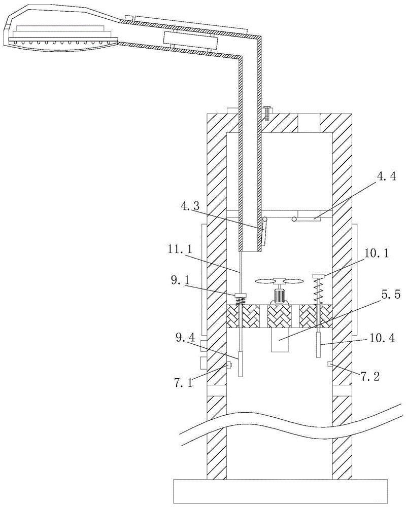
附图标记:1灯杆;1.1进气孔;2底板;3顶板;3.1第一插孔;3.2第二插孔;4上固定板;4.1第一上通孔;4.2第二上通孔;4.3第一活动盖;4.4第二活动盖;5下固定板;5.1第一下通孔;5.2第二下通孔;5.3贯通孔;5.4散热风扇;5.5第一蓄电池;6.1第一太阳能电池板;6.2第一控制器;6.3第一无线通信单元;7.1激光发射器;7.2光强检测器;9.1第一挡块;9.2第一弹簧;9.3第一插杆;9.4第一透光片;10.1第二挡块;10.2第二弹簧;10.3第二插杆;10.4第二透光片;11竖杆;11.1挤压杆;11.2限位块;11.3紧固螺栓;12连接杆;12.1第二蓄电池;12.2第二太阳能电池板;12.3第二无线通信单元;13.1灯罩;13.2出气孔;13.3透光罩;13.4安装电路板;13.5导热块;13.6散热翅片;13.7LED灯珠;13.8第二控制器。Reference signs: 1 light pole; 1.1 air inlet; 2 bottom plate; 3 top plate; 3.1 first jack; 3.2 second jack; 4 upper fixing plate; 4.1 first upper through hole; 4.2 second upper through hole; 4.3 The first movable cover; 4.4 The second movable cover; 5 The lower fixed plate; 5.1 The first lower through hole; 5.2 The second lower through hole; 5.3 The through hole; ; 6.2 The first controller; 6.3 The first wireless communication unit; 7.1 Laser transmitter; 7.2 Light intensity detector; 9.1 The first block; 9.2 The first spring; 10.2 Second spring; 10.3 Second insertion rod; 10.4 Second light-transmitting sheet; 11 Vertical rod; 11.1 Extrusion rod; 11.2 Limit block; 11.3 Fastening bolt; 12 Connecting rod; 12.1 Second battery ;12.2 The second solar panel; 12.3 The second wireless communication unit; 13.1 Lampshade; 13.2 Air outlet; 13.3 Light transmission cover; device.
一种高效散热太阳能LED路灯,包括灯杆组件和灯头组件,所述灯杆组件包括中空的灯杆1、固定于灯杆顶部的封闭灯杆顶部开口的顶板3和固定于灯杆底部的底板2,所述灯杆的外侧壁固定有第一太阳能电池板6.1、第一控制器6.2和第一无线通信单元6.3,所述第一无线通孔单元与所述第一控制器连接,所述顶板具有第一插孔3.1和第二插孔3.2,所述灯杆内固定有上固定板4和与所述上固定板相互平行的下固定板5,所述上固定板上具有第一上通孔4.1和第二上通孔4.2,所述上固定板的下表面还通过第一弹性复位铰接部件铰接有第一活动盖4.3,且通过第二弹性复位铰接部件铰接有第二活动盖4.4,无外力时,所述第一活动盖封闭所述第一上通孔,所述第二活动盖封闭所述第二上通孔,所述下固定板具有第一下通孔5.1、第二下通孔5.2和两个贯穿下固定板上、下表面的贯穿孔5.3,所述下固定板的上表面固定有散热风扇5.4,所述下固定板的下表面固定有第一蓄电池5.5,所述第一下通孔处插有第一插杆9.3,所述第一插杆的顶部具有第一挡块9.1,所述第一插杆的底部具有第一透光片9.4,所述第一挡块和所述下固定板之间具有套在所述第一插杆上的第一弹簧9.2,所述第二下通孔处插有第二插杆10.3,所述第二插杆的顶部具有第二挡块10.2,所述第二插杆的底部具有第二透光片10.4,所述第二挡块和所述下固定板之间具有套在所述第二插杆上的第二弹簧10.2,所述灯杆的内侧壁固定有激光发射器和光强检测器,所述激光发射器7.1和光强检测器7.2均位于所述下固定板下方,且激光发射器的光轴与所述第一、二透光片均平行,所述灯杆的侧壁还具有进气孔,所述进气孔位于所述下固定板下方,所述第一太阳能电池板用于为第一蓄电池充电,所述第一蓄电池用于为激光发射器、光强检测器和散热风扇供电,所述第一插孔、第二插孔、第一上通孔和第二上通孔的截面均为矩形;所述灯头组件包括竖杆、灯头和连接所述竖杆和灯头的连接杆,所述竖杆11和连接杆12均为中空结构,所述竖杆的底端敞口,所述灯头包括灯罩13.1和透光镜13.3,所述灯罩内具有安装电路板13.4、设置在安装电路板处的LED灯珠13.7、与所述安装电路板抵接的导热块13.5和设置在导热块上的散热翅片13.6,所述灯罩具有出气孔13.2,所述灯罩内还具有第二控制器,所述连接杆的顶部安装有第二无线通信单元和第二太阳能电池板,所述连接杆内通过固定支架固定有第二蓄电池12.1,所述第二无线通信单元与所述第二控制器12.3连接,所述第二太阳能电池板12.2用于为第二蓄电池充电,所述第二蓄电池用于为所述灯头供电,所述竖杆的底部固定连接有竖直的挤压杆,所述竖杆的外侧壁还固定有用于与所述顶板的上表面抵接的限位块;当所述灯杆组件安装有两个所述灯头组件时,一个灯头组件的竖杆穿过第一插孔和第一上通孔且该灯头组件的挤压杆抵接挤压第一挡块从而使得激光发射器的光轴穿过所述第一透光片,另一个灯头组件的竖杆穿过第二插孔和第二上通孔且该灯头组件的挤压杆抵接挤压第二挡块从而使得激光发射器的光轴穿过所述第二透光片;当所述灯杆组件安装有一个所述灯头组件时,该灯头组件的竖杆穿过第一插孔和第一上通孔且该灯头组件的挤压杆抵接挤压第一挡块从而使得激光发射器的光轴穿过所述第一透光片,或者该灯头组件的竖杆穿过第二插孔和第二上通孔且该灯头组件的挤压杆抵接挤压第二挡块从而使得激光发射器的光轴穿过所述第二透光片;当所述灯杆组件没有安装所述灯头组件时,所述第一活动盖封闭所述第一上通孔,所述第二活动盖封闭所述第二上通孔,所述第一、二透光片均位于所述激光发射器的光轴的上方;所述第一控制器进行控制,在启动散热风扇时,同时启动激光发射器7.1和光强检测器7.2,当光强检测器的测量值在第一范围内时,使散热风扇以第一转速转动,当光强检测器的测量值在第二范围内时,使散热风扇以第二转速转动,所述第二转速大于第一转速,所述第一范围的最小值大于第二范围的最大值。A high-efficiency heat-dissipating solar LED street light, comprising a light pole assembly and a lamp head assembly, the light pole assembly includes a
所述第一、二透光片的透光率均为50%。所述灯头组件的竖杆的高度大于1米。所述第一太阳能电池板为薄膜太阳能电池板。所述第一太阳能电池板的数量为两块。所述底板处具有安装孔。所述竖杆的外截面和内截面均为矩形。所述限位块处具有用于将限位块和顶板固定的紧固螺栓。所述第一活动盖和第二活动盖面对所述上固定板的表面均具有橡胶垫。所述第二转速是第一转速的两倍。The light transmittances of the first and second light-transmitting sheets are both 50%. The height of the vertical rod of the lamp head assembly is greater than 1 meter. The first solar cell panel is a thin film solar cell panel. The number of the first solar cell panels is two. The bottom plate has mounting holes. Both the outer section and the inner section of the vertical rod are rectangular. The limit block is provided with a fastening bolt for fixing the limit block and the top plate. Surfaces of the first movable cover and the second movable cover facing the upper fixing plate have rubber pads. The second rotational speed is twice the first rotational speed.
本发明的路灯,灯杆组件和灯头组件是组装式的,可以根据需要安装一个灯头组件或两个灯头组件。灯杆组件包含第一太阳能电池板、第一蓄电池、第一控制器和第一无线通信单元,能够实现独立的供电和远程控制。灯头组件包含第二太阳能电池板、第二蓄电池、第二控制器和第二无线通信单元,能够进行独立的供电和远程控制。具体应用时,远程控制中心可以手动控制或设定程序控制,使得灯头和散热风扇同时启动和关闭,以获得最好的散热效果并且避免散热风扇的能量浪费。当散热风扇启动时,第一控制器同时启动激光发射器和光强检测器,当光强检测器的测量值在第一范围内时(此时如图1所示,激光发射器的光仅经过一个透光片,因此光强检测器的测量值较大),使散热风扇以第一转速转动,当光强检测器的测量值在第二范围内时(此时如图2所示,激光发射器的光经过两个透光片,因此光强检测器的测量值较小,使散热风扇以第二转速转动,所述第二转速大于第一转速。即,当只有一个灯头组件时,散热风扇以低转速进行散热,当有两个灯头组件时,散热风扇以高转速进行散热。避免散热风量不足,也避免了散热风扇消耗过大的能量。The street lamp of the present invention, the lamp pole assembly and the lamp head assembly are assembled, and one lamp head assembly or two lamp head assemblies can be installed according to requirements. The light pole assembly includes a first solar panel, a first storage battery, a first controller and a first wireless communication unit, and can realize independent power supply and remote control. The lamp head assembly includes a second solar panel, a second battery, a second controller and a second wireless communication unit, and is capable of independent power supply and remote control. In specific applications, the remote control center can manually control or set program control, so that the lamp head and the cooling fan can be turned on and off at the same time, so as to obtain the best cooling effect and avoid the energy waste of the cooling fan. When the cooling fan is started, the first controller starts the laser transmitter and the light intensity detector at the same time. When the measured value of the light intensity detector is within the first range (as shown in Fig. 1 at this time, the light of the laser transmitter is only After passing through a light-transmitting sheet, the measured value of the light intensity detector is relatively large), and the cooling fan is rotated at the first speed. When the measured value of the light intensity detector is within the second range (as shown in Figure 2 at this time, The light from the laser emitter passes through the two light-transmitting sheets, so the measured value of the light intensity detector is small, so that the cooling fan rotates at a second rotational speed that is greater than the first rotational speed. That is, when there is only one lamp head assembly , The cooling fan dissipates heat at a low speed, and when there are two lamp head assemblies, the cooling fan dissipates heat at a high speed to avoid insufficient cooling air volume and excessive energy consumption by the cooling fan.
具体散热时,散热气流从进气孔进入,经过贯穿孔,从竖杆的底部进入竖杆内(如图1所示,当未插入竖杆时,活动盖是盖住通孔的,不会造成散热气流的浪费),再进入连接杆内,再进入灯罩内,从出气孔出来,进行散热。When dissipating heat, the cooling airflow enters from the air inlet, passes through the through hole, and enters the vertical rod from the bottom of the vertical rod (as shown in Figure 1, when the vertical rod is not inserted, the movable cover covers the through hole and does not Causes waste of heat dissipation airflow), then enters the connecting rod, then enters the lampshade, and comes out from the air outlet for heat dissipation.
尽管本发明就优选实施方式进行了示意和描述,但本领域的技术人员应当理解,只要不超出本发明的权利要求所限定的范围,可以对本发明进行各种变化和修改。Although the present invention has been illustrated and described in terms of preferred embodiments, those skilled in the art will appreciate that various changes and modifications can be made to the present invention without departing from the scope defined by the claims of the invention.
Claims (6)
Priority Applications (1)
| Application Number | Priority Date | Filing Date | Title |
|---|---|---|---|
| CN201810287251.0A CN108679552B (en) | 2018-04-03 | 2018-04-03 | A high-efficiency heat dissipation solar LED street light |
Applications Claiming Priority (1)
| Application Number | Priority Date | Filing Date | Title |
|---|---|---|---|
| CN201810287251.0A CN108679552B (en) | 2018-04-03 | 2018-04-03 | A high-efficiency heat dissipation solar LED street light |
Publications (2)
| Publication Number | Publication Date |
|---|---|
| CN108679552A CN108679552A (en) | 2018-10-19 |
| CN108679552B true CN108679552B (en) | 2020-10-27 |
Family
ID=63800612
Family Applications (1)
| Application Number | Title | Priority Date | Filing Date |
|---|---|---|---|
| CN201810287251.0A Active CN108679552B (en) | 2018-04-03 | 2018-04-03 | A high-efficiency heat dissipation solar LED street light |
Country Status (1)
| Country | Link |
|---|---|
| CN (1) | CN108679552B (en) |
Families Citing this family (4)
| Publication number | Priority date | Publication date | Assignee | Title |
|---|---|---|---|---|
| CN109595532B (en) * | 2018-10-31 | 2020-05-15 | 嘉善力通信息科技股份有限公司 | Can install communication module's lamp pole for wisdom city |
| CN109630985B (en) * | 2018-10-31 | 2020-10-30 | 山东华方智联科技股份有限公司 | Multi-functional wisdom lamp pole |
| CN112245869A (en) * | 2020-10-14 | 2021-01-22 | 高海东 | Leg pressing device |
| CN114811496B (en) * | 2022-03-15 | 2023-09-12 | 江苏省飞花灯饰制造有限公司 | Solar LED street lamp based on high-efficiency power generation foldable power generation unit |
Family Cites Families (19)
| Publication number | Priority date | Publication date | Assignee | Title |
|---|---|---|---|---|
| EP1447619A1 (en) * | 2003-02-12 | 2004-08-18 | Exterieur Vert S.A. | Lighting device, in particular projector-like sealed luminaire recessed in the ground, cooled by air circulation |
| CN201145183Y (en) * | 2008-01-15 | 2008-11-05 | 香港理工大学 | Combined LED lamp holder |
| CN201373526Y (en) * | 2009-03-24 | 2009-12-30 | 张明荣 | Laboratory ventilating device |
| CN102072432B (en) * | 2009-11-24 | 2012-07-18 | 贵州世纪天元矿业有限公司 | Light-emitting diode (LED) street lamp structure, LED lamp cap cooling method |
| CN102346704A (en) * | 2010-08-03 | 2012-02-08 | 鸿富锦精密工业(深圳)有限公司 | System for monitoring server simulation loads and method |
| KR101201490B1 (en) * | 2010-12-07 | 2012-11-14 | 경희대학교 산학협력단 | Eco-friendly louver type LED luminaire with DSSCDye-sensitized solar cell |
| CN102359838B (en) * | 2011-08-10 | 2014-04-09 | 陈拥军 | Laser pressure sensor |
| CN202303158U (en) * | 2011-10-31 | 2012-07-04 | 深圳市百得力电子有限公司 | LED (Light-Emitting Diode) lamp |
| CN102411418B (en) * | 2012-01-12 | 2013-07-03 | 东莞市品宇电子科技有限公司 | Notebook computer cooling pad with capabilities of detecting temperature and adjusting rotating speed of fan |
| CN204513089U (en) * | 2015-01-19 | 2015-07-29 | 高锦波 | A kind of LED street light |
| CN204460057U (en) * | 2015-03-23 | 2015-07-08 | 崔豪光 | Street lamp |
| CN106369537A (en) * | 2016-11-01 | 2017-02-01 | 刘贤平 | Energy-saving LED street lamp capable of dissipating heat and removing dust |
| CN107062149B (en) * | 2017-06-12 | 2023-05-09 | 山东明碁照明有限公司 | High-efficient heat dissipation solar energy LED street lamp |
| CN206786596U (en) * | 2017-06-12 | 2017-12-22 | 杨晓艳 | A kind of high efficiency and heat radiation solar LED street lamp |
| CN206958776U (en) * | 2017-07-18 | 2018-02-02 | 浙江华严建设有限公司 | A kind of LED street lamp |
| CN107465133B (en) * | 2017-08-13 | 2019-04-05 | 重庆鹏达电气有限责任公司 | A kind of electric power cabinet and its cooling control method |
| CN107293954B (en) * | 2017-08-13 | 2019-05-07 | 深圳市欧亚特电器设备有限公司 | A built-in heat-dissipating power cabinet capable of isolating vibration and its heat-dissipating control method |
| CN207065390U (en) * | 2017-08-28 | 2018-03-02 | 扬州市松佳照明电器有限公司 | A kind of two-burner lamp street lamp based on wind-cooling heat dissipating |
| CN107579446B (en) * | 2017-09-15 | 2019-02-05 | 宁波博恩电气有限公司 | Can automatic heat radiation distribution box |
-
2018
- 2018-04-03 CN CN201810287251.0A patent/CN108679552B/en active Active
Also Published As
| Publication number | Publication date |
|---|---|
| CN108679552A (en) | 2018-10-19 |
Similar Documents
| Publication | Publication Date | Title |
|---|---|---|
| CN108679552B (en) | A high-efficiency heat dissipation solar LED street light | |
| CN107062149B (en) | High-efficient heat dissipation solar energy LED street lamp | |
| CN206817351U (en) | A kind of adjustable type Down lamp | |
| CN209294933U (en) | A kind of LED light with gaseous exchange radiator structure | |
| CN204901556U (en) | LED industrial and mining modulated structure | |
| CN207893654U (en) | A kind of Projecting Lamp and the supporting structure for positioning Projecting Lamp | |
| CN104534322B (en) | A kind of pure light-operated high light efficiency LED electricity-saving lamp | |
| CN201753908U (en) | Automatic temperature control type forced radiator for LED high-power lighting lamp | |
| CN206739064U (en) | A kind of adjustable LED illumination lamp of light angle | |
| CN204785902U (en) | Annular sidelight LED movie & TV lamp | |
| CN211853799U (en) | Thing networking solar energy LED street lamp convenient to installation is maintained | |
| CN204026408U (en) | The LED ceiling light that a kind of thermal diffusivity is good | |
| CN220038394U (en) | Lamp cap heat radiation structure of LED street lamp | |
| CN207539654U (en) | A kind of LED bulb being easily installed | |
| CN208124053U (en) | An outdoor LED corrugated light with double waterproof | |
| CN207246820U (en) | A kind of drawing and pulling type light source appliance plate Tri-proof light | |
| CN201844296U (en) | Optical energy heat dissipation type LED lamp | |
| CN208504088U (en) | A kind of light-operated LED road lamp | |
| CN205102088U (en) | Radiator and adopt emitting diode street lamp of this radiator | |
| CN216844548U (en) | Novel LED lighting device | |
| CN217131203U (en) | A self-heating semiconductor LED street light | |
| CN221705426U (en) | A waterproof LED floodlight | |
| CN219550296U (en) | Low-energy-consumption light source assembly for LED street lamp | |
| CN222278501U (en) | LED projection lamp with efficient heat dissipation performance | |
| CN218544343U (en) | Solar street lamp shell structure |
Legal Events
| Date | Code | Title | Description |
|---|---|---|---|
| PB01 | Publication | ||
| PB01 | Publication | ||
| SE01 | Entry into force of request for substantive examination | ||
| SE01 | Entry into force of request for substantive examination | ||
| TA01 | Transfer of patent application right |
Effective date of registration: 20200923 Address after: 225600 001 Hao Wei Avenue, Gaoyou City, Yangzhou, Jiangsu Applicant after: YANGZHOU LUEYANG TECHNOLOGY Co.,Ltd. Address before: 225600, Gaoyou Town, Jiangsu City, Gaoyou province Yangzhou industrial concentration area Applicant before: YANGZHOU TONGLVE TECHNOLOGY DEVELOPMENT Co.,Ltd. |
|
| TA01 | Transfer of patent application right | ||
| GR01 | Patent grant | ||
| GR01 | Patent grant | ||
| TR01 | Transfer of patent right |
Effective date of registration: 20230105 Address after: 225600 industrial zone of Gaoyou City, Yangzhou City, Jiangsu Province Patentee after: Jiangsu Xingke Electric Co.,Ltd. Address before: 225600 No.001 Haowei Avenue, Songqiao Town, Gaoyou City, Yangzhou City, Jiangsu Province Patentee before: YANGZHOU LUEYANG TECHNOLOGY Co.,Ltd. |
|
| TR01 | Transfer of patent right | ||
| TR01 | Transfer of patent right |
Effective date of registration: 20231226 Address after: 225000 Old Village Department, Baishu Village, Gongdao Town, Hanjiang District, Yangzhou City, Jiangsu Province Patentee after: Jiangsu puzhiguang Lighting Engineering Co.,Ltd. Address before: 225600 industrial zone of Gaoyou City, Yangzhou City, Jiangsu Province Patentee before: Jiangsu Xingke Electric Co.,Ltd. |
|
| TR01 | Transfer of patent right | ||
| TR01 | Transfer of patent right |
Effective date of registration: 20250520 Address after: 225600 Jiangsu Province Yangzhou City Gaoyou City Lingtang Hui Autonomous Township Industrial Concentration Area Qilong Village Datian Group 28-1 Patentee after: Jiangsu Yukun Metal Products Co.,Ltd. Country or region after: China Address before: 225000 Old Village Department, Baishu Village, Gongdao Town, Hanjiang District, Yangzhou City, Jiangsu Province Patentee before: Jiangsu puzhiguang Lighting Engineering Co.,Ltd. Country or region before: China |
|
| TR01 | Transfer of patent right |