CN108612552B - an anchor - Google Patents
an anchor Download PDFInfo
- Publication number
- CN108612552B CN108612552B CN201810383091.XA CN201810383091A CN108612552B CN 108612552 B CN108612552 B CN 108612552B CN 201810383091 A CN201810383091 A CN 201810383091A CN 108612552 B CN108612552 B CN 108612552B
- Authority
- CN
- China
- Prior art keywords
- anchor
- rod body
- movable end
- tray
- rod
- Prior art date
- Legal status (The legal status is an assumption and is not a legal conclusion. Google has not performed a legal analysis and makes no representation as to the accuracy of the status listed.)
- Active
Links
- 239000011435 rock Substances 0.000 claims abstract description 81
- 230000008878 coupling Effects 0.000 claims description 5
- 238000010168 coupling process Methods 0.000 claims description 5
- 238000005859 coupling reaction Methods 0.000 claims description 5
- 230000004323 axial length Effects 0.000 claims description 4
- 230000009286 beneficial effect Effects 0.000 abstract description 4
- 238000006073 displacement reaction Methods 0.000 description 7
- 238000000034 method Methods 0.000 description 6
- 238000004873 anchoring Methods 0.000 description 5
- 238000005516 engineering process Methods 0.000 description 5
- 230000008569 process Effects 0.000 description 4
- 230000007423 decrease Effects 0.000 description 3
- 239000002689 soil Substances 0.000 description 3
- 230000008093 supporting effect Effects 0.000 description 3
- 230000015572 biosynthetic process Effects 0.000 description 2
- 238000010586 diagram Methods 0.000 description 2
- 230000007774 longterm Effects 0.000 description 2
- 238000012986 modification Methods 0.000 description 2
- 230000004048 modification Effects 0.000 description 2
- 102000004190 Enzymes Human genes 0.000 description 1
- 108090000790 Enzymes Proteins 0.000 description 1
- 238000004891 communication Methods 0.000 description 1
- 238000009792 diffusion process Methods 0.000 description 1
- 230000000694 effects Effects 0.000 description 1
- 230000005489 elastic deformation Effects 0.000 description 1
- JEIPFZHSYJVQDO-UHFFFAOYSA-N iron(III) oxide Inorganic materials O=[Fe]O[Fe]=O JEIPFZHSYJVQDO-UHFFFAOYSA-N 0.000 description 1
- 239000000463 material Substances 0.000 description 1
- 235000012149 noodles Nutrition 0.000 description 1
- 230000002093 peripheral effect Effects 0.000 description 1
- 230000002787 reinforcement Effects 0.000 description 1
- 239000004576 sand Substances 0.000 description 1
- 230000003068 static effect Effects 0.000 description 1
- 238000006467 substitution reaction Methods 0.000 description 1
- 230000007704 transition Effects 0.000 description 1
- XLYOFNOQVPJJNP-UHFFFAOYSA-N water Substances O XLYOFNOQVPJJNP-UHFFFAOYSA-N 0.000 description 1
Images

Classifications
-
- E—FIXED CONSTRUCTIONS
- E21—EARTH OR ROCK DRILLING; MINING
- E21D—SHAFTS; TUNNELS; GALLERIES; LARGE UNDERGROUND CHAMBERS
- E21D21/00—Anchoring-bolts for roof, floor in galleries or longwall working, or shaft-lining protection
- E21D21/0026—Anchoring-bolts for roof, floor in galleries or longwall working, or shaft-lining protection characterised by constructional features of the bolts
-
- E—FIXED CONSTRUCTIONS
- E02—HYDRAULIC ENGINEERING; FOUNDATIONS; SOIL SHIFTING
- E02D—FOUNDATIONS; EXCAVATIONS; EMBANKMENTS; UNDERGROUND OR UNDERWATER STRUCTURES
- E02D17/00—Excavations; Bordering of excavations; Making embankments
- E02D17/20—Securing of slopes or inclines
-
- E—FIXED CONSTRUCTIONS
- E02—HYDRAULIC ENGINEERING; FOUNDATIONS; SOIL SHIFTING
- E02D—FOUNDATIONS; EXCAVATIONS; EMBANKMENTS; UNDERGROUND OR UNDERWATER STRUCTURES
- E02D5/00—Bulkheads, piles, or other structural elements specially adapted to foundation engineering
- E02D5/74—Means for anchoring structural elements or bulkheads
-
- E—FIXED CONSTRUCTIONS
- E21—EARTH OR ROCK DRILLING; MINING
- E21D—SHAFTS; TUNNELS; GALLERIES; LARGE UNDERGROUND CHAMBERS
- E21D21/00—Anchoring-bolts for roof, floor in galleries or longwall working, or shaft-lining protection
- E21D21/0086—Bearing plates
Landscapes
- Engineering & Computer Science (AREA)
- Mining & Mineral Resources (AREA)
- Structural Engineering (AREA)
- Life Sciences & Earth Sciences (AREA)
- General Life Sciences & Earth Sciences (AREA)
- Paleontology (AREA)
- Civil Engineering (AREA)
- General Engineering & Computer Science (AREA)
- Geochemistry & Mineralogy (AREA)
- Geology (AREA)
- Devices Affording Protection Of Roads Or Walls For Sound Insulation (AREA)
- Piles And Underground Anchors (AREA)
Abstract
本发明提供一种锚杆,包括杆体和托盘,所述杆体包括连接锚尾的扩长段,所述扩长段与锚尾套装有可相对杆体滑动的扩长装置,扩长段设有凸部结构,所述扩长装置为具有活动端的套筒,活动端末端位于凸部结构前端,可用以与凸部结构咬合或滑脱;所述锚尾用以活动端滑动至锚尾时限制活动端的运动;所述托盘可拆卸的安装于所述套筒,托盘在锚杆锚固完毕时紧压在锚杆插入的岩壁。本发明的有益效果体现在,通过扩长装置的设置,实现当围岩发生一定变形时,锚杆的长度得到延伸,使围岩中的变形能得到释放,锚杆延伸之后,仍然能够保持工作阻力,再次维持围岩的稳定。

The invention provides an anchor rod, comprising a rod body and a tray, the rod body includes an extended section connected to the anchor tail, the extended section and the anchor tail are sleeved with an extension device that can slide relative to the rod body, and the extended section is provided with a convex The extension device is a sleeve with a movable end, and the end of the movable end is located at the front end of the convex structure, which can be used to engage or slip off with the convex structure; the anchor tail is used to limit the movement of the movable end when the movable end slides to the anchor tail. Movement; the tray is detachably mounted on the sleeve, and the tray is pressed against the rock wall into which the bolt is inserted when the bolt is anchored. The beneficial effect of the present invention is embodied in that when the surrounding rock is deformed to a certain extent, the length of the anchor rod can be extended, so that the deformation in the surrounding rock can be released, and the anchor rod can still keep working after the extension device. resistance to maintain the stability of the surrounding rock again.
Description
技术领域technical field
本发明涉及土木工程的防护设施技术,具体涉及一种锚杆,可应用于隧道、边坡等支护工程。The invention relates to a protection facility technology for civil engineering, in particular to an anchor rod, which can be applied to supporting projects such as tunnels and side slopes.
背景技术Background technique
岩土工程中的锚固技术是应用锚杆或锚索对岩体进行加固,它充分地发挥岩土体自身的稳定能力,是一种对原岩扰动小、施工速度快、安全可靠、又是经济有效的加固技术。锚杆能主动加固岩土体,有效控制其变形,防止岩土体的坍塌破坏,锚杆支护技术的诸多优越性,使锚杆支护技术已成为岩土工程领域的主要支护方式。The anchoring technology in geotechnical engineering is to use bolts or anchor cables to reinforce the rock mass. It gives full play to the stability of the rock and soil mass itself. Cost-effective reinforcement technology. The bolt can actively strengthen the rock and soil mass, effectively control its deformation, and prevent the collapse and damage of the rock and soil mass. The many advantages of the bolt support technology have made the bolt support technology the main support method in the field of geotechnical engineering.
然而,如深埋隧道或深部巷道围岩潜在变形能很大,在围岩高应力条件下,常常表现出“大变形”的特点,具体表现为软岩大变形、岩爆大变形、冲击大变形、瓦斯突出大变形。而现有技术中的锚杆极限拉伸长度小,当地下工程围岩发生较大的变形时,锚杆往往不能适用围岩的大变形而出现锚头失效、锚杆拉断等破坏,进而引发塌方、冒顶等事故,甚至造成地下工程功能的丧失。由于锚杆自身不可弯曲、与围岩摩擦力小等原因,不能达到理想的锚固效果。当围岩变形逐渐增大,由于普通锚杆抗拉刚度大、抗剪能力差的原因,不能提供足够的弹性变形,产生锚杆与围岩拉脱、锚杆被拉断、托盘失效等问题,最终导致锚杆等支护设备失效,给工程带来不可预估的损伤,严重时或许会造成重大安全事故。However, the potential deformation energy of surrounding rock in deep tunnels or deep roadways is very large. Under the condition of high stress of surrounding rock, it often shows the characteristics of "large deformation", which is embodied in large deformation of soft rock, large deformation of rock burst, and large impact. Deformation, gas outburst large deformation. However, the limit tensile length of the bolt in the prior art is small. When the surrounding rock of the underground project is greatly deformed, the bolt often cannot be applied to the large deformation of the surrounding rock, and the failure of the bolt head and the rupture of the bolt occur. Accidents such as landslides and roof fall are caused, and even the loss of underground engineering functions. The ideal anchoring effect cannot be achieved due to the fact that the bolt itself cannot be bent and the friction force with the surrounding rock is small. When the deformation of the surrounding rock gradually increases, due to the high tensile stiffness and poor shear resistance of the ordinary bolt, it cannot provide sufficient elastic deformation, resulting in problems such as the pull-off of the bolt and the surrounding rock, the broken bolt, and the failure of the pallet. , which will eventually lead to the failure of supporting equipment such as anchor rods, which will bring unpredictable damage to the project, and may cause major safety accidents in severe cases.
由于锚杆钢筋自身的延伸率低,在极限应力下发生微小的变形便有可能被拉断,而锚杆一旦被拉断,则整个锚杆支护系统将会失效。因此,为避免上述地质灾害的发生,如何提供一种可在围岩发生变形时,能在一定范围内适应围岩移动的锚杆,使其起到良好的支护效果,是需要解决的重要技术问题。Due to the low elongation of the anchor bar itself, a slight deformation under the ultimate stress may be broken, and once the anchor bar is broken, the entire bolt support system will fail. Therefore, in order to avoid the occurrence of the above-mentioned geological disasters, how to provide a bolt that can adapt to the movement of the surrounding rock within a certain range when the surrounding rock is deformed, so that it has a good supporting effect, is an important problem to be solved. technical problem.
发明内容SUMMARY OF THE INVENTION
针对现有技术中存在的问题,本发明需要解决的技术问题是,提供一种锚杆,可以提高锚杆适应围岩变形的能力,提供有效的锚杆支护。Aiming at the problems existing in the prior art, the technical problem to be solved by the present invention is to provide a bolt, which can improve the ability of the bolt to adapt to the deformation of surrounding rock and provide effective bolt support.
本发明的技术方案是,提供一种锚杆,包括杆体和托盘,所述杆体包括连接锚尾的扩长段,所述扩长段与锚尾套装有可相对杆体滑动的扩长装置,扩长段设有凸部结构,所述扩长装置为具有活动端的套筒,活动端末端位于凸部结构前端,可用以与凸部结构咬合或滑脱;所述锚尾用以活动端滑动至锚尾时限制活动端的运动;所述托盘可拆卸的安装于所述套筒,托盘在锚杆锚固完毕时紧压在锚杆插入的岩壁。The technical scheme of the present invention is to provide an anchor rod, which includes a rod body and a tray, the rod body includes an extended section connected to the anchor tail, the extended section and the anchor tail are sleeved with an expansion device that can slide relative to the rod body, and the extended section and the anchor tail are sleeved. The long section is provided with a convex structure, the expansion device is a sleeve with a movable end, and the end of the movable end is located at the front end of the convex structure, which can be used to engage or slip off with the convex structure; the anchor tail is used for the movable end to slide to the anchor The movement of the movable end is restricted at the tail end; the tray is detachably installed on the sleeve, and the tray is pressed against the rock wall into which the bolt is inserted when the bolt is anchored.
优选方案,所述活动端为一开孔的空心圆柱结构,所述孔内径与杆体直径相等,活动端内圆面紧贴于杆体外圆面。Preferably, the movable end is a hollow cylindrical structure with an opening, the inner diameter of the hole is equal to the diameter of the rod body, and the inner circular surface of the movable end is closely attached to the outer circular surface of the rod.
优选方案,所述活动端内圆面设有与扩长段外圆面凸部结构相耦合的耦合结构。Preferably, the inner circular surface of the movable end is provided with a coupling structure coupled with the convex structure of the outer circular surface of the extended section.
优选方案,所述杆体与活动端承载能力大于凸部结构的承载能力。Preferably, the bearing capacity of the rod body and the movable end is greater than the bearing capacity of the convex structure.
优选方案,所述锚尾、套筒、活动端和托盘的承载能力与杆体承载能力相匹配。Preferably, the bearing capacity of the anchor tail, the sleeve, the movable end and the tray matches the bearing capacity of the rod body.
优选方案,所述凸部结构的承载能力沿所述杆体扩长段至锚尾方向渐增。In a preferred solution, the bearing capacity of the protruding portion structure increases gradually along the direction from the extended section of the rod body to the anchor tail.
优选方案,所述凸部结构之间的间距沿所述杆体扩长段至锚尾方向渐减。In a preferred solution, the distance between the protruding structures gradually decreases along the direction from the extended section of the rod body to the anchor tail.
优选方案,所述凸部结构沿所述杆体径向的厚度沿所述杆体扩长段至锚尾方向渐增。Preferably, the thickness of the convex portion structure along the radial direction of the rod body increases gradually along the direction from the extended section of the rod body to the anchor tail.
优选方案,所述凸部结构沿所述杆体轴向的宽度沿所述杆体扩长段至锚尾方向渐增。In a preferred solution, the width of the convex portion structure along the axial direction of the rod body increases gradually along the direction from the extended section of the rod body to the anchor tail.
优选方案,所述凸部结构可为螺纹。Preferably, the protrusion structure may be a thread.
优选方案,所述凸部结构可为沿所述杆体外圆面的环状柱体结构。Preferably, the protruding portion structure may be an annular cylindrical structure along the outer circumference of the rod.
优选方案,所述锚尾为圆柱体结构,所述圆柱体结构直径大于所述套筒活动端孔的内径。Preferably, the anchor tail is a cylindrical structure, and the diameter of the cylindrical structure is larger than the inner diameter of the movable end hole of the sleeve.
优选方案,所述活动端轴向长度与扩长段长度相等。Preferably, the axial length of the movable end is equal to the length of the extended section.
优选方案,所述套筒另一端设有封盖。Preferably, the other end of the sleeve is provided with a cover.
优选方案,所述套筒包括调节装置,用以调节锚杆锚固后托盘距离岩壁间的距离。Preferably, the sleeve includes an adjusting device for adjusting the distance between the pallet and the rock wall after the bolt is anchored.
优选方案,所述托盘底部设有与所述套筒外径适配的通孔;所述调节装置包括螺母,套筒设有与所述螺母适配的螺纹,所述螺母处于旋拧结束状态时,托盘紧压在锚杆插入的岩壁。Preferably, the bottom of the tray is provided with a through hole adapted to the outer diameter of the sleeve; the adjusting device includes a nut, the sleeve is provided with a thread adapted to the nut, and the nut is in the finished state of screwing When the pallet is pressed against the rock wall where the bolt is inserted.
本发明的有益效果体现在,提供一种锚杆,可有效提高锚杆适应围岩变形的能力,从而提供有效的锚杆支护。通过扩长装置的设置,实现当围岩发生一定变形时,锚杆的长度得到延伸,使围岩中的变形能得到释放,锚杆延伸之后,仍然能够保持工作阻力,再次维持围岩的稳定;所述套筒活动端与扩长段凸起结构的配合设置,实现围岩发生变形时扩长装置随之与杆体发生相对位移从而适应围岩变形,在不损坏杆体承载能力的同时提供锚杆进一步支护的结构支持;套筒封盖的设置,可有效防止水分及杂物进入套筒内部;套筒调节装置的设置,可利于调节锚杆锚固后托盘距离岩壁间的距离。The beneficial effect of the present invention is to provide an anchor rod, which can effectively improve the ability of the anchor rod to adapt to the deformation of surrounding rocks, thereby providing effective anchor rod support. Through the setting of the expansion device, when the surrounding rock is deformed to a certain extent, the length of the bolt can be extended, so that the deformation in the surrounding rock can be released. After the bolt is extended, the working resistance can still be maintained, and the stability of the surrounding rock can be maintained again. ;The matching arrangement of the movable end of the sleeve and the raised structure of the expansion section can realize the relative displacement of the expansion device and the rod body when the surrounding rock is deformed, so as to adapt to the deformation of the surrounding rock, and provide anchors without damaging the bearing capacity of the rod body. The rod is further supported by the structure; the sleeve cover can effectively prevent moisture and sundries from entering the sleeve; the sleeve adjustment device can be used to adjust the distance between the tray and the rock wall after the bolt is anchored.
附图说明:Description of drawings:
图1为本发明实施例一种锚杆结构示意图;FIG. 1 is a schematic structural diagram of an anchor rod according to an embodiment of the present invention;
图2为本发明实施例所述扩长装置局部结构示意图。FIG. 2 is a schematic diagram of a partial structure of an extension device according to an embodiment of the present invention.
附图标记说明Description of reference numerals
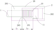
1.杆体,10.扩长段,101.凸部结构,11.锚尾,2.扩长装置,20.套筒,201.活动端,202.封盖,203.活动端末端,3.托盘,4.螺母。1. Rod body, 10. Extending section, 101. Convex structure, 11. Anchor tail, 2. Extending device, 20. Sleeve, 201. Active end, 202. Cover, 203. Active end end, 3. Tray, 4. Nut.
具体实施方式Detailed ways
下面将结合本发明实施例中的附图,对本发明实施例中的技术方案进行清楚、完整地描述,显然,所描述的实施例仅仅是本发明一部分实施例,而不是全部的实施例。基于本发明中的实施例,本领域普通技术人员在没有做出创造性劳动前提下所获得的所有其他实施例,都属于本发明保护的范围。The technical solutions in the embodiments of the present invention will be clearly and completely described below with reference to the accompanying drawings in the embodiments of the present invention. Obviously, the described embodiments are only a part of the embodiments of the present invention, rather than all the embodiments. Based on the embodiments of the present invention, all other embodiments obtained by those of ordinary skill in the art without creative efforts shall fall within the protection scope of the present invention.
请参阅图1-2所示,本发明提供的具体实施例如下:Please refer to Fig. 1-2, the specific embodiments provided by the present invention are as follows:
本实施例的一种锚杆,包括杆体1和托盘3,所述杆体包括连接锚尾11的扩长段10,所述扩长段与锚尾外套装有可相对杆体滑动的扩长装置2,扩长段10设有凸部结构101,所述扩长装置2为具有活动端201的套筒20,活动端末端203位于凸部结构前端(所述前端和后端为相对概念,以朝向锚尾的方向称为后端方向,背离锚尾的方向则为前端方向),可用以与凸部结构咬合或滑脱;所述锚尾11用以活动端201滑动至锚尾11时限制活动端的运动;所述托盘3可拆卸的安装于所述套筒20,托盘在锚杆锚固完毕时紧压在锚杆插入的岩壁。现有技术中,通常由于锚杆钢筋自身的延伸率低,在极限应力下发生微小的变形便有可能被拉断,而锚杆一旦被拉断,则整个锚杆支护系统将会失效。因此,本实施例中采用通过扩展锚杆长度而适应围岩发生变形的技术方案,并随着围岩变形进展过程中,保证锚杆提供逐渐增大的工作阻力。本实施例所述锚杆在进行锚固时,锚杆锚固段锚固于山体或岩层中,将扩长装置套装于杆体扩长段上,托盘在锚杆锚固完毕时紧压在锚杆插入的岩壁。锚固完毕时,活动端末端位于凸部结构前端位置。在稳定状态下,扩长装置紧紧的套装于杆体上,套筒活动端与杆体处于相对静止状态;当围岩出现变形,其初期的变形能较大,若围岩的变形能超过锚杆所能承受的范围,活动端将沿锚尾方向移动与杆体产生相对位移(图1中箭头所指方向为所述活动端移动方向,即扩长装置相对于杆体的移动方向),破坏凸部结构并滑脱;此间围岩的变形能得到释放,当其变形能小于锚杆的承载能力,活动端末端将位于另一凸部结构前端位置,活动端与杆体不再产生位移而回到平衡状态,扩长装置再次紧紧的套装于杆体上。采用上述方案,当围岩发生一定变形时,由于扩长装置的设置,锚杆长度得到延伸,使围岩中的变形能得到释放,锚杆延伸之后,仍然能够保持工作阻力,再次维持围岩的稳定。An anchor rod in this embodiment includes a
优选实施例方案,所述活动端为一开孔的空心圆柱结构,所述孔内径与杆体直径相等,活动端内圆面紧贴于杆体外圆面。为利于扩长装置套装于所述杆体,本实施例中将活动端设为一开孔的空心圆柱结构,所述孔内径与杆体直径相等,有利于活动端内圆面紧贴于杆体外圆面。In a preferred embodiment, the movable end is a hollow cylindrical structure with an opening, the inner diameter of the hole is equal to the diameter of the rod body, and the inner circular surface of the movable end is closely attached to the outer circular surface of the rod. In order to facilitate the expansion device to be sleeved on the rod body, in this embodiment, the movable end is set as a hollow cylindrical structure with an opening, and the inner diameter of the hole is equal to the diameter of the rod body, which is beneficial for the inner circular surface of the movable end to be close to the outer circumference of the rod. noodle.
优选实施例方案,所述活动端内圆面设有与扩长段外圆面凸部结构相耦合的耦合结构。当围岩出现变形,若围岩的变形能超过锚杆所能承受的范围,活动端将沿锚尾方向移动与杆体产生相对位移,破坏凸部结构并滑脱。在此过程中为了推迟凸部结构的破坏时间,给围岩一定时间释放形变能,通过活动端内圆面设有与扩长段外圆面凸部结构相耦合的耦合结构,一方面可增强活动端与杆体相对移动的阻力,从而达到延长锚杆使用寿命的目的;另一方面,当围岩中的变形能得到释放,再次回到稳定状态时,活动端与杆体不再产生位移,并通过耦合结构使活动端与扩长段咬合在一起,也利于扩长装置再次紧紧的套装于杆体上。In a preferred embodiment, the inner circular surface of the movable end is provided with a coupling structure coupled with the convex structure of the outer circular surface of the extended section. When the surrounding rock is deformed, if the deformation of the surrounding rock exceeds the range that the anchor rod can bear, the movable end will move in the direction of the anchor tail and produce relative displacement with the rod body, destroying the convex structure and slipping off. In this process, in order to delay the failure time of the convex structure and give the surrounding rock a certain time to release the deformation energy, the inner circular surface of the movable end is provided with a coupling structure coupled with the convex structure of the outer circular surface of the extended section. On the other hand, when the deformation in the surrounding rock can be released and return to a stable state, the movable end and the rod will no longer be displaced, and Through the coupling structure, the movable end and the expansion section are engaged together, which is also beneficial for the expansion device to be tightly sheathed on the rod body again.
优选实施例方案,所述杆体与活动端承载能力大于凸部结构的承载能力。本实施例中,为保证套筒活动端与杆体发生相对位移过程中,当围岩的变形能超过锚杆所能承受的范围使活动端能破坏凸部结构(但不破坏锚杆杆体)从而滑脱产生相对位移,设计所述杆体与活动端的承载能力大于凸部结构的承载能力。In a preferred embodiment, the bearing capacity of the rod body and the movable end is greater than the bearing capacity of the convex structure. In this embodiment, in order to ensure that during the relative displacement between the movable end of the sleeve and the rod body, when the deformation of the surrounding rock exceeds the range that the anchor rod can bear, the movable end can destroy the convex structure (but not the rod body of the anchor rod), thereby The slipping produces relative displacement, and the bearing capacity of the rod body and the movable end is designed to be greater than the bearing capacity of the convex structure.
优选实施例方案,所述锚尾、套筒、活动端和托盘的承载能力与杆体承载能力相匹配。随着围岩长期变形,活动端将沿锚尾方向移动与杆体产生相对位移,破坏凸部结构并滑脱,当活动端将杆体扩长段上设置的凸部结构全部破坏后,最终将抵至锚尾处维持平衡状态,锚尾最终将限制活动端继续运动。另一方面,围岩出现变形时,荷载作用于托盘,通过托盘将荷载传递到杆体,且托盘亦可变形,围岩应力得到释放,安全过渡到新的平衡阶段。因此托盘的承载能力也具有一定要求,如具有一定变形能力,当荷载较大时可压缩,不致脆裂失效,具有一定面积,有利于锚杆预应力扩散。而托盘通过可拆卸的安装于套筒,套筒的承载能力也应该满足一定要求。因此,本实施例中对于锚尾的承载能力要求较高,将锚尾、套筒、活动端和托盘的承载能力与杆体承载能力相匹配。In a preferred embodiment, the bearing capacity of the anchor tail, the sleeve, the movable end and the tray matches the bearing capacity of the rod body. With the long-term deformation of the surrounding rock, the movable end will move in the direction of the anchor tail and produce relative displacement with the rod body, destroying the convex structure and slipping off. A state of balance is maintained at the tail of the anchor, which will eventually limit the continued movement of the active end. On the other hand, when the surrounding rock is deformed, the load acts on the pallet, and the load is transmitted to the rod body through the pallet, and the pallet can also be deformed, the stress of the surrounding rock is released, and the transition to a new equilibrium stage is safe. Therefore, the bearing capacity of the pallet also has certain requirements, such as a certain deformation capacity, when the load is large, it can be compressed without brittle failure, and it has a certain area, which is conducive to the prestress diffusion of the anchor. The tray is detachably mounted on the sleeve, and the carrying capacity of the sleeve should also meet certain requirements. Therefore, in this embodiment, the requirements for the bearing capacity of the anchor tail are relatively high, and the bearing capacity of the anchor tail, the sleeve, the movable end and the tray is matched with the bearing capacity of the rod body.
优选实施例方案,所述凸部结构的承载能力沿所述杆体扩长段至锚尾方向渐增。本实施例中锚杆锚固后,若围岩发生变形,超过锚杆所能承受的范围,活动端将沿锚尾方向移动与杆体产生相对位移,破坏凸部结构并滑脱,此间围岩释放形变能重新回到稳定状态。当围岩再次发生变形,为进一步增强活动端与杆体相对移动的阻力,本实施例中设计扩长段上的凸部结构沿所述杆体扩长段至锚尾方向渐增,实现当围岩再次发生变形,增强活动端沿锚尾方向移动破坏凸部结构时的阻力。In a preferred embodiment, the bearing capacity of the protruding portion structure increases gradually along the direction from the rod body extended section to the anchor tail. In this embodiment, after the bolt is anchored, if the surrounding rock is deformed beyond the range that the bolt can bear, the movable end will move in the direction of the anchor tail and the rod body will be displaced, destroying the structure of the convex part and slipping off, during which the deformation of the surrounding rock is released. return to a stable state. When the surrounding rock is deformed again, in order to further enhance the resistance of the relative movement between the movable end and the rod body, in this embodiment, the convex structure on the extended section is designed to gradually increase from the extended section of the rod body to the anchor tail. Deformation occurs again, increasing the resistance of the movable end when it moves in the direction of the anchor tail to destroy the convex structure.
优选实施例方案,所述凸部结构之间的间距沿所述杆体扩长段至锚尾方向渐减。本实施例中,多个凸部结构之间的间距沿所述杆体扩长段至锚尾方向渐减。通常,围岩初期的变形能较大,当超过锚杆的承载能力范围后,为使锚杆适应围岩较大的变形,避免锚杆在围岩变形过程中拉断,本实施例中采用扩长装置在围岩变形前期相对杆体移动较容易的方案来解决。具体来说,扩长段前端外圆面设置的凸部结构之间的间距较后端间距大些,从而利于扩长装置在围岩变形前期相对杆体移动。In a preferred embodiment, the distance between the protruding structures gradually decreases along the direction from the extended section of the rod body to the anchor tail. In this embodiment, the distance between the plurality of protruding structures gradually decreases along the direction from the extended section of the rod body to the anchor tail. Usually, the deformation energy of the surrounding rock is relatively large at the initial stage. When the bearing capacity of the anchor rod is exceeded, in order to make the anchor rod adapt to the large deformation of the surrounding rock and avoid the anchor rod being pulled off during the deformation process of the surrounding rock, in this embodiment, the The expansion device is easier to move relative to the rod body in the early stage of surrounding rock deformation. Specifically, the distance between the convex structures arranged on the outer circular surface of the front end of the expansion section is larger than the distance at the rear end, thereby facilitating the movement of the expansion device relative to the rod body in the early stage of deformation of the surrounding rock.
优选实施例方案,所述凸部结构沿所述杆体径向的厚度沿所述杆体扩长段至锚尾方向渐增。通常,围岩初期的变形能较大,当超过锚杆的承载能力范围后,为使锚杆适应围岩较大的变形,避免锚杆在围岩变形过程中拉断,本实施例中采用扩长装置在围岩变形前期相对杆体移动较容易的方案来解决。具体来说,扩长段前端外圆面设置的凸部结构的径向厚度较后端厚度小些,使得套筒活动端在杆体移动时更容易破坏凸部结构并滑脱,从而利于扩长装置在围岩变形前期相对杆体移动。In a preferred embodiment, the thickness of the convex portion structure along the radial direction of the rod body increases gradually along the direction from the extended section of the rod body to the anchor tail. Usually, the deformation energy of the surrounding rock is relatively large at the initial stage. When the bearing capacity of the anchor rod is exceeded, in order to make the anchor rod adapt to the large deformation of the surrounding rock and avoid the anchor rod being pulled off during the deformation process of the surrounding rock, in this embodiment, the The expansion device is easier to move relative to the rod body in the early stage of surrounding rock deformation. Specifically, the radial thickness of the convex structure provided on the outer circular surface of the front end of the expansion section is smaller than that of the rear end, so that the movable end of the sleeve is more likely to damage the convex structure and slip off when the rod body moves, thereby facilitating the expansion device. Movement relative to the rod body in the early stage of surrounding rock deformation.
优选实施例方案,所述凸部结构沿所述杆体轴向的宽度沿所述杆体扩长段至锚尾方向渐增。通常,围岩初期的变形能较大,当超过锚杆的承载能力范围后,为使锚杆适应围岩较大的变形,避免锚杆在围岩变形过程中拉断,本实施例中采用扩长装置在围岩变形前期相对杆体移动较容易的方案来解决。具体来说,扩长段前端外圆面设置的凸部结构的轴向宽度较后端宽度小些,使得套筒活动端在杆体移动时更容易破坏凸部结构并滑脱,从而利于扩长装置在围岩变形前期相对杆体移动。In a preferred embodiment, the width of the protruding portion structure along the axial direction of the rod body increases gradually along the direction from the extended section of the rod body to the anchor tail. Usually, the deformation energy of the surrounding rock is relatively large at the initial stage. When the bearing capacity of the anchor rod is exceeded, in order to make the anchor rod adapt to the large deformation of the surrounding rock and avoid the anchor rod being pulled off during the deformation process of the surrounding rock, in this embodiment, the The expansion device is easier to move relative to the rod body in the early stage of surrounding rock deformation. Specifically, the axial width of the convex structure provided on the outer circular surface of the front end of the expansion section is smaller than the width of the rear end, so that the movable end of the sleeve is more likely to damage the convex structure and slip off when the rod body moves, thereby facilitating the expansion device. Movement relative to the rod body in the early stage of surrounding rock deformation.
优选实施例方案,所述凸部结构可为螺纹。In a preferred embodiment, the protrusion structure may be a thread.
优选实施例方案,所述凸部结构可为沿所述杆体外圆面的环状柱体结构。In a preferred embodiment, the protruding portion structure may be an annular cylindrical structure along the outer circumference of the rod.
优选实施例方案,所述锚尾为圆柱体结构,所述圆柱体结构直径大于所述套筒活动端孔的内径。随着围岩长期变形,活动端将沿锚尾方向移动与杆体产生相对位移,逐渐破坏凸部结构并滑脱,当活动端将杆体扩长段上设置的凸部结构全部破坏后,最终将抵至锚尾处维持平衡状态,锚尾最终将限制活动端继续运动。In a preferred embodiment, the anchor tail is a cylindrical structure, and the diameter of the cylindrical structure is larger than the inner diameter of the movable end hole of the sleeve. With the long-term deformation of the surrounding rock, the movable end will move in the direction of the anchor tail and produce relative displacement with the rod body, gradually destroying the convex structure and slipping off. To maintain equilibrium at the anchor tail, the anchor tail will eventually limit the movement of the active end.
优选实施例方案,所述活动端轴向长度与扩长段长度相等。本实施例中设置活动端轴向长度L1与扩长段长度L2相等,可实现当活动端将杆体扩长段上设置的凸部结构全部破坏后,最终活动端末端将抵至锚尾处维持平衡状态,锚尾最终将限制活动端继续运动,提高锚杆的稳定性。In a preferred embodiment, the axial length of the movable end is equal to the length of the extended section. In this embodiment, the axial length L 1 of the movable end is set equal to the length L 2 of the extended section, which can realize that when the movable end destroys all the convex structures provided on the extended section of the rod body, the end of the movable end will finally touch the anchor tail The anchor tail will eventually limit the continuous movement of the movable end and improve the stability of the anchor rod.
优选实施例方案,所述套筒另一端设有封盖202。本实施例中在套筒的另一端(即活动端相对的另一端)设置封盖,一方面,锚杆在潮湿环境下工作时可防止水分进入扩长装置而导致扩长装置与杆体的连接酶发生锈蚀,另一方面,还可防止泥沙或石子等杂物进入套筒内部。In a preferred embodiment, the other end of the sleeve is provided with a
优选实施例方案,所述套筒包括调节装置,用以调节锚杆锚固后托盘距离岩壁间的距离。当锚杆锚固段锚固于山体或岩层中,将扩长装置套装于杆体扩长段上,通过调节装置,可以使拖盘在锚杆锚固完毕时紧压在锚杆插入的岩壁。In a preferred embodiment, the sleeve includes an adjusting device for adjusting the distance between the pallet and the rock wall after the bolt is anchored. When the anchoring section of the bolt is anchored in the mountain or rock formation, the expansion device is sleeved on the expansion section of the rod body, and through the adjustment device, the drag plate can be tightly pressed against the rock wall where the bolt is inserted when the bolt is anchored.
优选实施例方案,所述托盘3底部设有与所述套筒20外径适配的通孔;所述调节装置包括螺母4,套筒设有与所述螺母适配的螺纹,所述螺母处于旋拧结束状态时,托盘紧压在锚杆插入的岩壁。具体的,所述托盘底部穿过套筒,通过螺母旋拧于套筒,从而调整托盘距离岩壁间的距离,当螺母旋拧结束后,托盘紧压在锚杆插入的岩壁。另一方面,围岩出现变形时,荷载作用于托盘,通过托盘将荷载传递到锚杆杆体,通过扩长装置增大锚杆的工作阻力,进而控制围岩变形。In a preferred embodiment, the bottom of the tray 3 is provided with a through hole adapted to the outer diameter of the
在本发明的实施例的描述中,需要理解的是,术语“上”、“下”、“前”、“后”、“左”、“右”、“坚直”、“水平”、“中心”、“顶”、“底”、“顶部”、“底部”、“内”、“外”、“内侧”、“外侧”等指示的方位或位置关系为基于附图所示的方位或位置关系,仅是为了使于描述本发明和简化描述,而不是指示或暗示所指的装置或元件必须具有特定的方位、以特定的方位构造和操作,因此不能理解为对本发明的限制。其中,“里侧”是指内部或围起来的区域或空间。“外围”是指某特定部件或特定区域的周围的区域。In the description of the embodiments of the present invention, it should be understood that the terms "upper", "lower", "front", "rear", "left", "right", "straight", "horizontal", " The orientation or positional relationship indicated by center, top, bottom, top, bottom, inner, outer, inner, outer, etc. is based on the orientation shown in the drawings or The positional relationship is only for the purpose of describing the present invention and simplifying the description, rather than indicating or implying that the indicated device or element must have a specific orientation, be constructed and operated in a specific orientation, and therefore should not be construed as a limitation of the present invention. Among them, "inside" refers to the interior or enclosed area or space. "Peripheral" refers to the area surrounding a particular component or particular area.
在本发明的实施例的描述中,术语“第一”、“第二”、“第三”、“第四”仅用以描述目的,而不能理解为指示或暗示相对重要性或者隐含指明所指示的技术特征的数量。由此,限定有“第一”、“第二”、“第三”、“第四”的特征可以明示或者隐含地包括一个或者更多个该特征。在本发明的描述中,除非另有说明,“多个”的含义是两个或两个以上。In the description of the embodiments of the present invention, the terms "first", "second", "third", and "fourth" are only used for descriptive purposes, and should not be construed as indicating or implying relative importance or implicitly indicating Number of technical features indicated. Thus, a feature defined as "first", "second", "third", "fourth" may expressly or implicitly include one or more of that feature. In the description of the present invention, unless otherwise specified, "plurality" means two or more.
在本发明的实施例的描述中,需要说明的是,除非另有明确的规定和限定,术语“安装”、“相连”、“连接”、“组装”应做广义理解,例如,可以是固定连接,也可以是可拆卸连接,或一体地连接;可以是直接相连,也可以通过中间媒介间接相连,可以是两个元件内部的连通。对于本领域的普通技术人员而言,可以具体情况理解上述术语在本发明中的具体含义。In the description of the embodiments of the present invention, it should be noted that, unless otherwise expressly specified and limited, the terms "installed", "connected", "connected" and "assembled" should be understood in a broad sense, for example, it may be fixed The connection can also be a detachable connection, or an integral connection; it can be a direct connection, or an indirect connection through an intermediate medium, and it can be the internal communication of the two elements. For those of ordinary skill in the art, the specific meanings of the above terms in the present invention can be understood in specific situations.
在本发明的实施例的描述中,具体特征、结构、材料或者特点可以在任何的一个或多个实施例或示例中以合适的方式结合。In the description of embodiments of the invention, the particular features, structures, materials or characteristics may be combined in any suitable manner in any one or more embodiments or examples.
在本发明的实施例的描述中,需要理解的是,“-”和“~”表示的是两个数值之同的范围,并且该范围包括端点。例如:“A-B”表示大于或等于A,且小于或等于B的范围。“A~B”表示大于或等于A,且小于或等于B的范围。In the description of the embodiments of the present invention, it should be understood that "-" and "-" represent a range between two numerical values, and the range includes the endpoints. For example: "A-B" means a range greater than or equal to A and less than or equal to B. "A to B" means a range greater than or equal to A and less than or equal to B.
在本发明的实施例的描述中,本文中术语“和/或”,仅仅是一种描述关联对象的关联关系,表示可以存在三种关系,例如,A和/或B,可以表示:单独存在A,同时存在A和B,单独存在B这三种情况。另外,本文中字符“/”,一般表示前后关联对象是一种“或”的关系。In the description of the embodiments of the present invention, the term "and/or" herein is only an association relationship for describing associated objects, indicating that there may be three kinds of relationships, for example, A and/or B, which may indicate that: exist independently A, there are both A and B, and there are three cases of B alone. In addition, the character "/" in this document generally indicates that the related objects are an "or" relationship.
尽管已经示出和描述了本发明的实施例,对于本领域的普通技术人员而言,可以理解在不脱离本发明的原理和精神的情况下可以对这些实施例进行多种变化、修改、替换和变型,本发明的范围由所附权利要求及其等同物限定。Although embodiments of the present invention have been shown and described, it will be understood by those skilled in the art that various changes, modifications, and substitutions can be made in these embodiments without departing from the principle and spirit of the invention and modifications, the scope of the present invention is defined by the appended claims and their equivalents.
Claims (3)
Priority Applications (1)
| Application Number | Priority Date | Filing Date | Title |
|---|---|---|---|
| CN201810383091.XA CN108612552B (en) | 2018-04-26 | 2018-04-26 | an anchor |
Applications Claiming Priority (1)
| Application Number | Priority Date | Filing Date | Title |
|---|---|---|---|
| CN201810383091.XA CN108612552B (en) | 2018-04-26 | 2018-04-26 | an anchor |
Publications (2)
| Publication Number | Publication Date |
|---|---|
| CN108612552A CN108612552A (en) | 2018-10-02 |
| CN108612552B true CN108612552B (en) | 2020-12-04 |
Family
ID=63661213
Family Applications (1)
| Application Number | Title | Priority Date | Filing Date |
|---|---|---|---|
| CN201810383091.XA Active CN108612552B (en) | 2018-04-26 | 2018-04-26 | an anchor |
Country Status (1)
| Country | Link |
|---|---|
| CN (1) | CN108612552B (en) |
Families Citing this family (1)
| Publication number | Priority date | Publication date | Assignee | Title |
|---|---|---|---|---|
| CN117188497A (en) * | 2023-09-22 | 2023-12-08 | 山西四建集团有限公司 | A high slope support construction structure and construction method |
Citations (5)
| Publication number | Priority date | Publication date | Assignee | Title |
|---|---|---|---|---|
| US4850746A (en) * | 1987-04-18 | 1989-07-25 | Dyckerhoff & Widmann Aktiengesellschaft | Rock anchor assembly for securing roadways and wall surfaces of open cuts and tunnels |
| CN201924947U (en) * | 2010-11-17 | 2011-08-10 | 江苏省矿业工程集团有限公司建井工程处 | Extendable anchor rod |
| CN104594928A (en) * | 2014-12-31 | 2015-05-06 | 中国矿业大学 | Four-dimensional support large deformation anchor rod |
| CN204591323U (en) * | 2015-05-07 | 2015-08-26 | 山东科技大学 | Large elongation is anti-corrosion anchor pole |
| CN205445647U (en) * | 2016-03-27 | 2016-08-10 | 山东科技大学 | Dual pretension lets step by step presses stock tray |
Family Cites Families (2)
| Publication number | Priority date | Publication date | Assignee | Title |
|---|---|---|---|---|
| CN202866845U (en) * | 2012-09-02 | 2013-04-10 | 山东科技大学 | Deformation resisting anchor rope/anchor rod capable of detecting anchoring quality timely |
| CN106193031A (en) * | 2016-07-19 | 2016-12-07 | 成都鹏程路桥机械有限公司 | A kind of dust-proof anchorage |
-
2018
- 2018-04-26 CN CN201810383091.XA patent/CN108612552B/en active Active
Patent Citations (5)
| Publication number | Priority date | Publication date | Assignee | Title |
|---|---|---|---|---|
| US4850746A (en) * | 1987-04-18 | 1989-07-25 | Dyckerhoff & Widmann Aktiengesellschaft | Rock anchor assembly for securing roadways and wall surfaces of open cuts and tunnels |
| CN201924947U (en) * | 2010-11-17 | 2011-08-10 | 江苏省矿业工程集团有限公司建井工程处 | Extendable anchor rod |
| CN104594928A (en) * | 2014-12-31 | 2015-05-06 | 中国矿业大学 | Four-dimensional support large deformation anchor rod |
| CN204591323U (en) * | 2015-05-07 | 2015-08-26 | 山东科技大学 | Large elongation is anti-corrosion anchor pole |
| CN205445647U (en) * | 2016-03-27 | 2016-08-10 | 山东科技大学 | Dual pretension lets step by step presses stock tray |
Also Published As
| Publication number | Publication date |
|---|---|
| CN108612552A (en) | 2018-10-02 |
Similar Documents
| Publication | Publication Date | Title |
|---|---|---|
| CN110578542B (en) | A kind of high stress impact ground pressure roadway bolt, design method and working method | |
| CN204357467U (en) | Scalable internal-injection type secondary anchoring type anchor pole | |
| CN102536278B (en) | Progressive yielding combined-type extensible anchor rod and construction method thereof | |
| CN107237646A (en) | The quantitative method for protecting support in large deformation constant resistance supporting grouted anchor bar, anchor cable and tunnel | |
| CN104818723B (en) | Slope retaining friction pile | |
| CN107060851B (en) | Two-stage constant resistance large deformation anchor | |
| CN103758550B (en) | A liquid-expanding yielding pressure and anti-seismic anti-high ground temperature bolt | |
| WO2011153810A1 (en) | Constant resistance and large deformation anchor rod | |
| CN109162743B (en) | Friction-shearing combined quasi-constant-resistance large-deformation anchor cable | |
| CN111894643A (en) | Constant resistance body and constant resistance casing assembly and NPR anchor rod/cable | |
| CN107218072A (en) | A kind of extrusion friction type constant-resistance allows pressure large deformation anchor rod | |
| CN103104271B (en) | An anchor cable fracture impact buffer protection device | |
| CN107747500A (en) | A kind of pressure-relieving achor bar | |
| CN203296794U (en) | Yielding extensible fiber reinforced plastic anchor rod | |
| CN109339840B (en) | A torsional large deformation anchor | |
| CN205117379U (en) | Let pressure stock from advancing formula large deformation | |
| CN108343457A (en) | A kind of anchor pole being suitable for surrouding rock deformation | |
| CN102536280B (en) | Resistance-increasing yielding anchor rod | |
| CN108612552B (en) | an anchor | |
| CN212898562U (en) | Let pressure stock | |
| CN110617094A (en) | Shock-absorbing positioning composite grouting anchor rod capable of strengthening anchoring effect | |
| CN207437107U (en) | A kind of pressure-release anchor cable | |
| CN204783078U (en) | Cavity slip casting stock with constant -resistance of shocking resistance performance | |
| CN201981537U (en) | Water expansion type elastic anchor rod for resisting rock burst | |
| CN108316957A (en) | A kind of resistance-enlarging-type anchor pole |
Legal Events
| Date | Code | Title | Description |
|---|---|---|---|
| PB01 | Publication | ||
| PB01 | Publication | ||
| SE01 | Entry into force of request for substantive examination | ||
| SE01 | Entry into force of request for substantive examination | ||
| GR01 | Patent grant | ||
| GR01 | Patent grant |