CN108598999B - Crossing structure interfacing apparatus and crossing structure - Google Patents
Crossing structure interfacing apparatus and crossing structure Download PDFInfo
- Publication number
- CN108598999B CN108598999B CN201810554649.6A CN201810554649A CN108598999B CN 108598999 B CN108598999 B CN 108598999B CN 201810554649 A CN201810554649 A CN 201810554649A CN 108598999 B CN108598999 B CN 108598999B
- Authority
- CN
- China
- Prior art keywords
- section
- butt joint
- travel switch
- joint
- sleeve
- Prior art date
- Legal status (The legal status is an assumption and is not a legal conclusion. Google has not performed a legal analysis and makes no representation as to the accuracy of the status listed.)
- Active
Links
Images


Classifications
-
- H—ELECTRICITY
- H02—GENERATION; CONVERSION OR DISTRIBUTION OF ELECTRIC POWER
- H02G—INSTALLATION OF ELECTRIC CABLES OR LINES, OR OF COMBINED OPTICAL AND ELECTRIC CABLES OR LINES
- H02G1/00—Methods or apparatus specially adapted for installing, maintaining, repairing or dismantling electric cables or lines
- H02G1/02—Methods or apparatus specially adapted for installing, maintaining, repairing or dismantling electric cables or lines for overhead lines or cables
Abstract
The invention provides a crossing frame butt joint device and a crossing frame, which comprise an inserting part and a receiving part; the inserting part comprises a first flange plate and a convex butt joint coaxially connected with the first flange plate; the bearing part comprises a second flange plate and a sleeve coaxially connected with the second flange plate; an elastic piece, a transition piece and a concave butt joint which are connected with each other are sequentially arranged in the sleeve from the bottom to the opening; the sleeve comprises a combination section, a locking section and a limiting section, wherein the combination section is sequentially arranged from the bottom to the opening, the inner diameter of the combination section is gradually reduced, the locking section is used for preventing the convex butt joint and the concave butt joint from being separated, and the limiting section is used for limiting the concave butt joint to move outwards; a clamping hole which is vertical to the axial direction of the transition piece is formed in the side wall of the transition piece, and a spring clamp is arranged in the clamping hole; and an auxiliary buckle hole which is buckled with the spring is formed in the position, close to the bottom, of the combining section of the sleeve. The device effectively prevents the large arm from being disengaged during misoperation or accidental impact; accurate and quick unmanned butt joint is realized, and the safety and the efficiency of butt joint are improved.
Description
Technical Field
The invention relates to a crossing frame butt joint technology, in particular to a crossing frame butt joint device and a crossing frame.
Background
With the rapid development of ultrahigh voltage construction in China, in the construction process of newly-built power lines, the situations that cross-over construction is needed when the newly-built power lines are used in high-speed railways and highways of the built power lines are more and more. The crossing frame serving as a main construction machine and a safety measure for crossing construction can effectively guarantee engineering safety and efficient development, so that the improvement of the performance of the crossing frame is more and more emphasized by people.
In recent years, with the development and popularization of push-type and telescopic crossing frames, working conditions that two sides of the crossing frame are required to be connected in a large-arm mode in a butt joint mode are more and more, the existing crossing frames need to be connected in a high-altitude mode in a field, safety is poor, butt joint difficulty is high, construction time is long, and the requirements of crossing windows of high-speed rails and lines are difficult to meet; the safety, reliability and docking speed of the overhead docking device of the spanning frame form a bottleneck restricting the development of the spanning frame.
It is therefore desirable to provide a spanning frame docking assembly that meets the needs of the prior art.
Disclosure of Invention
Aiming at the defects of the prior art, the crossing frame butt joint device and the crossing frame are designed; the inserting part and the bearing part of the device can realize high-efficiency butt joint through the concave butt joint and the convex butt joint, and the concave butt joint is tightly matched with the sleeve, so that the position locking after butt joint and butt joint is realized, the reliability of butt joint is greatly improved, and the large arm disengagement in the misoperation or accidental impact process is effectively prevented; and the posture and the position of the large net sealing arm of the crossing frame can be effectively monitored and controlled through the inclination angle sensor and the positioning system which are arranged on the crossing frame, so that accurate and quick unmanned butt joint is realized, the butt joint safety and the butt joint efficiency are greatly improved, and a large amount of manpower and material resource investment is saved.
The purpose of the invention is realized by the following technical scheme:
the invention provides a crossing frame butt joint device, which comprises a plug-in part and a receiving part;
the plug-in part comprises a first flange plate and a convex butt joint coaxially connected with the first flange plate;
the bearing part comprises a second flange plate and a sleeve coaxially connected with the second flange plate; an elastic piece, a transition piece and a concave butt joint which are connected with each other are sequentially arranged in the sleeve from the bottom to the opening; the sleeve comprises a combination section, a position locking section and a limiting section, wherein the combination section is sequentially arranged from the bottom to the opening, the inner diameter of the combination section is gradually reduced, the position locking section is used for preventing the convex butt joint and the concave butt joint from being separated, and the limiting section is used for limiting the concave butt joint to move outwards;
a clamping hole which is vertical to the axial direction of the transition piece is formed in the side wall of the transition piece, and a spring clamp is arranged in the clamping hole; and an auxiliary buckle hole which is buckled with the spring is formed in the position, close to the bottom, of the combining section of the sleeve.
Preferably: the concave butt joint comprises two identical and symmetrically arranged half pipes, and each half pipe comprises a wide section, a middle section and a narrow section, wherein the inner diameters of the wide sections, the middle sections and the narrow sections are gradually decreased from inside to outside; the outer diameters of the wide section, the middle section and the narrow section are respectively equal to the inner diameter of the locking section.
Preferably, the following components: a curved section is arranged between the middle section and the narrow section; the inner wall of the curved section is curved, the inner diameter of the inner side of the curved section is equal to that of the middle section, and the inner diameter of the outer side of the curved section is equal to that of the narrow section.
Preferably: the transition piece comprises a connecting plate, and a spring pipe and a joint pipe which are respectively arranged on two sides of the connecting plate and are coaxially connected; the inner diameter of the spring tube is equal to the diameter of the connecting plate, and the elastic piece is coaxially arranged in the spring tube and connected with the spring tube.
Preferably: an annular groove is formed between the connecting plate and the joint pipe; one end of the inner side of the wide section is provided with an edge which is vertical to the axis of the wide section and is matched with the annular groove; the rim is inserted into the annular groove to effect connection of the female butt joint with the transition piece.
Preferably: a first travel switch, a second travel switch and a third travel switch are sequentially arranged on the outer side of the sleeve from outside to inside;
the first travel switch is arranged at one end of the outer side of the locking section, the induction element of the first travel switch is arranged at one end of the outer side of the concave butt joint, and the first travel switch is used for inducing whether the outer side of the concave butt joint reaches the outermost end of the locking section;
the second travel switch is arranged in the middle of the combining section, an induction element of the second travel switch is arranged at the front end of the convex butt joint, and the second travel switch is used for inducing whether the convex butt joint enters the concave butt joint or not;
the third travel switch is arranged at a position corresponding to the auxiliary buckle hole on the combining section, an induction element of the third travel switch is arranged in the auxiliary buckle hole of the transition piece, and the third travel switch is used for inducing whether the spring buckle enters the auxiliary buckle hole or not.
Preferably: the convex butt joint comprises a connecting rod and a convex block arranged at one end of the connecting rod; the diameter of the middle part of the lug is equal to the inner diameter of the middle section; the shape of the outer wall of the convex block from the middle part to the joint of the convex block and the connecting rod is matched with the inner wall of the curved section; the radius of the convex block is gradually decreased from the middle part to the free end.
Preferably: and the connecting plate is provided with a flaring coaxial with the connecting plate, and the inner wall of the flaring is matched with the outer wall of the front end of the bump.
Preferably: the inner wall of one end of the outer side of the limiting section is provided with a chamfer; an inclined section is arranged between the combining section and the locking section, the inner wall of the inclined section gradually inclines inwards from the joint of the combining section to the joint of the locking section, the inner diameter of the inclined section at the joint of the combining section is equal to that of the combining section, and the inner diameter of the inclined section at the joint of the combining section is equal to that of the locking section.
Preferably: the first flange plate and the second flange plate are respectively connected with the large arm to be butted of the crossing frame.
Preferably, the front end of the large net-sealing arm is provided with an inclination angle sensor and a positioning system, the positioning system is used for detecting the spatial position of the large net-sealing arm, and the inclination angle sensor is used for detecting the included angle between the large net-sealing arm and the horizontal line.
Based on the same inventive concept, the invention also provides a spanning frame comprising the docking device, which is characterized in that: the crossing frame comprises two frame bodies, two crossing assemblies which are arranged between the two frame bodies and are parallel to each other, and a hard seal net holding pole and an insulating net which are arranged between the two crossing assemblies; the crossing assembly comprises two symmetrical large net sealing arms; and the front end of the large net sealing arm is provided with a crossing frame butt joint device.
Compared with the closest prior art, the invention has the beneficial effects that:
1. according to the technical scheme provided by the invention, the plug-in part and the bearing part can realize efficient butt joint through the concave butt joint and the convex butt joint, and the concave butt joint and the sleeve are tightly matched, so that the position locking after butt joint and butt joint is realized, the butt joint reliability is greatly improved, and the large arm disengagement in the misoperation or accidental impact process is effectively prevented; and the posture and the position of the large net sealing arm of the crossing frame can be effectively monitored and controlled through the inclination angle sensor and the positioning system which are arranged on the crossing frame, so that accurate and quick unmanned butt joint is realized, the butt joint safety and the butt joint efficiency are greatly improved, and a large amount of manpower and material resource investment is saved.
2. According to the technical scheme provided by the invention, the inner wall of the concave butt joint and the outer wall of the convex butt joint are matched in design, are reasonable and tight, are convenient to butt, have excellent locking effect after butt joint, and greatly improve the efficiency of the butt joint process and the quality of the butt joint result.
3. According to the technical scheme provided by the invention, the design of the annular groove and the pawl can realize the position limitation of the concave butt joint after the plug-in part and the receiving part move in opposite directions greatly, so that the plug-in part and the receiving part move in opposite directions to realize the separation and the disassembly of the plug-in part and the receiving part, the disassembly and separation efficiency is effectively improved, and the device is convenient to be repeatedly used for many times.
4. According to the technical scheme provided by the invention, the three travel switches are arranged, and the positions of the concave butt joint and the transition piece are monitored, so that the control precision of the butt joint progress and the butt joint state in the butt joint process is further improved, the accuracy degree of butt joint is greatly improved, the misoperation is effectively avoided, the damage to the device is further avoided, and the safety of the butt joint and dismantling process is improved.
Drawings
The invention is further described below with reference to the accompanying drawings:
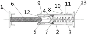
FIG. 1: the invention provides a cross sectional view of an axial plane before butt joint of a butt joint device;
FIG. 2: the invention provides a cross-sectional view of the shaft surface of a butt joint device after butt joint;
FIG. 3: the invention provides an axial plane sectional view of a butt joint device in a dismantling process;
FIG. 4 is a schematic view of: the invention provides a shaft surface section view of a sleeve;
FIG. 5: the invention provides a cross-sectional axial view of a transition piece;
FIG. 6: the invention provides a cross-sectional view of the axial surface of a concave butt joint;
FIG. 7: the invention provides a cross-sectional view of the axial surface of a convex butt joint;
reference numerals: 1-a first flange plate, 2-a sleeve, 3-an elastic part, 4-a transition part, 5-a concave butt joint, 6-a convex butt joint, 7-a spring buckle, 8-a secondary buckle hole, 9-a first travel switch, 10-a second travel switch, 11-a third travel switch, 12-a flaring and 13-a second flange plate;
21-a combination section, 22-a locking section, 23-a limiting section, 24-an inclined section and 25-a chamfer;
41-connecting plate, 42-spring tube, 43-joint tube and 44-annular groove;
51-wide section, 52-middle section, 53-narrow section, 54-curved section, 55-edge;
61-connecting rod, 62-lug.
Detailed Description
The technical solutions in the embodiments of the present application are clearly and completely described below with reference to the drawings in the embodiments of the present application.
As shown in fig. 1 to 7, the present invention provides a spanning frame docking apparatus, which includes a plug section and a receiving section;
the plug-in part comprises a first flange plate 1 and a convex butt joint 6 coaxially connected with the first flange plate 1;
the bearing part comprises a second flange plate 14 and a sleeve 2 coaxially connected with the second flange plate 14; an elastic part 3, a transition part 4 and a concave butt joint 5 which are connected with each other are sequentially arranged in the sleeve 2 from the bottom to the opening; the sleeve 2 comprises a combination section 21, a locking section 22 and a limiting section 23, wherein the combination section 21 is arranged from bottom to opening in sequence, the inner diameter of the combination section is gradually reduced, the combination section is used for butting the concave butt joint 5 and the convex butt joint 6, the locking section 22 is used for preventing the convex butt joint 6 and the concave butt joint 5 from being separated, and the limiting section 23 is used for limiting the outward movement of the concave butt joint 5; the female butt joint 5 and the male butt joint 6 are butted in the sleeve 2, and when the opening side of the female butt joint 5 moves to the combining section 21, the female butt joint 5 and the male butt joint 6 are butted;
a buckling hole which is vertical to the axial direction of the transition piece 4 is formed in the side wall of the transition piece, and a spring buckle 7 is arranged in the buckling hole; and a secondary buckle hole 8 matched with the spring buckle 7 is formed in the position, close to the bottom, of the combining section 21 of the sleeve 2.
Two spring plugs 8 for limiting the movement of the transition piece 4 are symmetrically arranged at the position, close to the bottom, of the joint section 21 of the sleeve 2; and an annular groove 7 matched with the spring plug 8 is arranged on the transition piece 4.
As shown in fig. 6, the female butt joint 5 includes two identical and symmetrically arranged half pipes, which include a wide section 51, a middle section 52 and a narrow section 53 arranged from right to left; the outer diameters of the wide section 51, the middle section 52 and the narrow section 53 are respectively equal to the inner diameter of the locking section 22; the inner diameters of the wide section 51, the middle section 52 and the narrow section 53 are sequentially decreased progressively; a curved section 54 is also arranged between the middle section 52 and the narrow section 53; the inner wall of the curved section 54 is curved, and has a right inner diameter equal to that of the middle section 52 and a left inner diameter equal to that of the narrow section 53.
The transition piece 4 comprises a connecting plate 41, and a spring tube 42 and a joint tube 43 which are respectively arranged on two sides of the connecting plate 41 and are coaxially connected; the elastic member 3 is coaxially disposed in the spring tube 42 and connected thereto.
An annular groove 44 is arranged between the connecting plate 41 and the joint 43; one end of the inner side of the wide section 51 is provided with an edge 55 which is vertical to the axis of the wide section and matched with the annular groove 44; the rim 55 is inserted into the annular groove 44 to effect the connection of the female abutment 5 with the transition piece 4.
A first travel switch 9, a second travel switch 10 and a third travel switch 11 are sequentially arranged on the outer side of the sleeve 2 from outside to inside;
the first travel switch 9 is arranged at one end of the outer side of the locking section 22, an induction element of the first travel switch is arranged at one end of the outer side of the concave butt joint 5, and the first travel switch 9 is used for inducing whether the outer side of the concave butt joint 5 reaches the outermost end of the locking section 22;
the second travel switch 10 is arranged in the middle of the combining section 21, an induction element of the second travel switch is arranged on the transition piece 4, and the second travel switch is used for inducing whether the male butt joint 6 enters the female butt joint 5 or not;
the third travel switch 11 is disposed at a position corresponding to the auxiliary snap hole 8 of the combining section 21, the sensing element of the third travel switch is disposed in the snap hole of the transition piece 4, and the third travel switch 11 is used for sensing whether the spring snap 7 enters the auxiliary snap hole 8.
The convex butt joint 6 comprises a connecting rod 61 and a convex block 62 arranged at one end of the connecting rod 61; the diameter of the middle portion of the projection 62 is equal to the inner diameter of the middle section 52; the shape of the outer wall of the lug 62 from the middle to the connection with the connecting rod is matched with the inner wall of the curved section; the projections 62 have a decreasing radius from the middle to the free end.
And a flaring 12 coaxial with the connecting plate is arranged on the connecting plate, and the inner wall of the flaring 12 is matched with the outer wall of the front end of the bump 62.
The inner wall of one end of the outer side of the limiting section 23 is provided with a chamfer 25; an inclined section 24 is arranged between the combining section 21 and the locking section 22, the inner wall of the inclined section 24 gradually inclines inwards from the joint of the inclined section 24 and the combining section 21 to the joint of the locking section 22, the inner diameter of the joint of the inclined section 24 and the combining section 21 is equal to the inner diameter of the combining section 21, and the inner diameter of the joint of the inclined section 24 and the locking section 22 is equal to the inner diameter of the locking section 22.
And the flange plate 1 of the receiving part and the flange plate 1 of the inserting part are respectively connected with the large arm to be butted of the spanning frame.
The large net sealing arm comprises a large net sealing arm body, and is characterized in that a tilt angle sensor and a positioning system are arranged at the front end of the large net sealing arm body, the positioning system is used for detecting the spatial position of the large net sealing arm body, and the tilt angle sensor is used for detecting the included angle between the large net sealing arm body and a horizontal line.
Example 2
Based on the same inventive concept, the invention also provides a spanning frame comprising the docking device, which is characterized in that: the crossing frame comprises two frame bodies, two crossing assemblies which are arranged between the two frame bodies and are parallel to each other, and a hard seal net holding pole and an insulating net which are arranged between the two crossing assemblies; the crossing assembly comprises two symmetrical large net sealing arms; and the front end of the large net sealing arm is provided with a crossing frame butt joint device.
Finally, it should be noted that: the embodiments described are only a part of the embodiments of the present application, and not all embodiments, and all other embodiments obtained by those skilled in the art without making creative efforts based on the embodiments in the present application belong to the protection scope of the present application.
Claims (5)
1. A spanning frame docking device comprises a plug-in part and a receiving part; the method is characterized in that: the plug-in part comprises a first flange plate and a convex butt joint coaxially connected with the first flange plate;
the bearing part comprises a second flange plate and a sleeve coaxially connected with the second flange plate; an elastic piece, a transition piece and a concave butt joint which are connected with each other are sequentially arranged in the sleeve from the bottom to the opening; the sleeve comprises a combination section, a position locking section and a limiting section, wherein the combination section is sequentially arranged from the bottom to the opening, the inner diameter of the combination section is gradually reduced, the position locking section is used for preventing the convex butt joint and the concave butt joint from being separated, and the limiting section is used for limiting the concave butt joint to move outwards;
a clamping hole which is vertical to the axial direction of the transition piece is formed in the side wall of the transition piece, and a spring clamp is arranged in the clamping hole; an auxiliary buckle hole buckled with the spring is formed in the position, close to the bottom, of the combining section of the sleeve;
the concave butt joint comprises two identical and symmetrically arranged half pipes, and each half pipe comprises a wide section, a middle section and a narrow section, wherein the inner diameters of the wide sections, the middle sections and the narrow sections are gradually decreased from inside to outside; the outer diameters of the wide section, the middle section and the narrow section are respectively equal to the inner diameter of the locking section;
a curved section is arranged between the middle section and the narrow section; the inner wall of the curved section is curved, the inner diameter of the inner side of the curved section is equal to that of the middle section, and the inner diameter of the outer side of the curved section is equal to that of the narrow section;
the transition piece comprises a connecting plate, and a spring pipe and a joint pipe which are respectively arranged on two sides of the connecting plate and are coaxially connected; the inner diameter of the spring tube is equal to the diameter of the connecting plate, and the elastic piece is coaxially arranged in the spring tube and connected with the spring tube;
an annular groove is formed between the connecting plate and the joint pipe; one end of the inner side of the wide section is provided with an edge which is vertical to the axis of the wide section and is matched with the annular groove; the rim is inserted into the annular groove to effect connection of the female butt joint with the transition piece;
a first travel switch, a second travel switch and a third travel switch are sequentially arranged on the outer side of the sleeve from outside to inside; the first travel switch is arranged at one end of the outer side of the locking section, the induction element of the first travel switch is arranged at one end of the outer side of the concave butt joint, and the first travel switch is used for inducing whether the outer side of the concave butt joint reaches the outermost end of the locking section; the second travel switch is arranged in the middle of the combining section, an induction element of the second travel switch is arranged at the front end of the convex butt joint, and the second travel switch is used for inducing whether the convex butt joint enters the concave butt joint or not;
the third travel switch is arranged at a position corresponding to the auxiliary buckle hole on the combining section, an induction element of the third travel switch is arranged in the buckle hole of the transition piece, and the third travel switch is used for inducing whether the spring buckle enters the auxiliary buckle hole or not;
the first flange plate and the second flange plate are respectively connected with a large arm to be butted of the spanning frame;
the front end of the large arm to be butted is provided with an inclination angle sensor and a positioning system, the positioning system is used for detecting the spatial position of the large net sealing arm, and the inclination angle sensor is used for detecting the included angle between the large net sealing arm and the horizontal line.
2. A spanning frame docking apparatus according to claim 1, wherein: the convex butt joint comprises a connecting rod and a convex block arranged at one end of the connecting rod; the diameter of the middle part of the lug is equal to the inner diameter of the middle section; the shape of the outer wall of the convex block from the middle part to the joint of the convex block and the connecting rod is matched with the inner wall of the curved section; the radius of the convex block is gradually decreased from the middle part to the free end.
3. A spanning frame docking apparatus according to claim 2, wherein: and the connecting plate is provided with a flaring coaxial with the connecting plate, and the inner wall of the flaring is matched with the outer wall of the front end of the bump.
4. A spanning frame docking apparatus according to claim 1, wherein: the inner wall of one end of the outer side of the limiting section is provided with a chamfer; an inclined section is arranged between the combining section and the locking section, the inner wall of the inclined section gradually inclines inwards from the joint of the combining section to the joint of the locking section, the inner diameter of the inclined section at the joint of the combining section is equal to that of the combining section, and the inner diameter of the inclined section at the joint of the combining section is equal to that of the locking section.
5. A spanning frame comprising a docking device according to any one of claims 1 to 4, wherein: the crossing frame comprises two frame bodies, two crossing assemblies which are arranged between the two frame bodies and are parallel to each other, and a hard seal net holding pole and an insulating net which are arranged between the two crossing assemblies; the crossing assembly comprises two symmetrical large net sealing arms; and the front end of the large net sealing arm is provided with a crossing frame butt joint device.
Priority Applications (1)
| Application Number | Priority Date | Filing Date | Title |
|---|---|---|---|
| CN201810554649.6A CN108598999B (en) | 2018-06-01 | 2018-06-01 | Crossing structure interfacing apparatus and crossing structure |
Applications Claiming Priority (1)
| Application Number | Priority Date | Filing Date | Title |
|---|---|---|---|
| CN201810554649.6A CN108598999B (en) | 2018-06-01 | 2018-06-01 | Crossing structure interfacing apparatus and crossing structure |
Publications (2)
| Publication Number | Publication Date |
|---|---|
| CN108598999A CN108598999A (en) | 2018-09-28 |
| CN108598999B true CN108598999B (en) | 2022-06-21 |
Family
ID=63630557
Family Applications (1)
| Application Number | Title | Priority Date | Filing Date |
|---|---|---|---|
| CN201810554649.6A Active CN108598999B (en) | 2018-06-01 | 2018-06-01 | Crossing structure interfacing apparatus and crossing structure |
Country Status (1)
| Country | Link |
|---|---|
| CN (1) | CN108598999B (en) |
Family Cites Families (6)
| Publication number | Priority date | Publication date | Assignee | Title |
|---|---|---|---|---|
| CN2412301Y (en) * | 2000-01-19 | 2000-12-27 | 国营群峰机械厂 | Four-column bridge live-wire work crossing rack |
| JP4629245B2 (en) * | 2001-02-13 | 2011-02-09 | エスアールジータカミヤ株式会社 | Pipe joint |
| CN102808521B (en) * | 2012-08-21 | 2015-06-17 | 上海通用金属结构工程有限公司 | High-altitude butting method and high-altitude butting device for heavy structures |
| CN103825218A (en) * | 2014-03-05 | 2014-05-28 | 国家电网公司 | 10KV circuit crossing assisting device |
| CN104878758B (en) * | 2015-06-09 | 2018-04-24 | 周兆弟 | Hale connection plug connector |
| CN105261897B (en) * | 2015-10-29 | 2018-01-02 | 福建源光电装有限公司 | Binding post joint anticreep detection means and its detection method |
-
2018
- 2018-06-01 CN CN201810554649.6A patent/CN108598999B/en active Active
Also Published As
| Publication number | Publication date |
|---|---|
| CN108598999A (en) | 2018-09-28 |
Similar Documents
| Publication | Publication Date | Title |
|---|---|---|
| CN109424807B (en) | Tongue-and-groove joint | |
| CN108598999B (en) | Crossing structure interfacing apparatus and crossing structure | |
| CN108808543B (en) | Crossing structure interfacing apparatus and crossing structure | |
| EP3869078A1 (en) | Sealing structure | |
| CN108649486B (en) | Crossing structure interfacing apparatus and crossing structure | |
| CN209909362U (en) | Novel flange for chemical pipeline | |
| CN105387296B (en) | A kind of pipeline docking crimping connector and its docking compression bonding method | |
| CN203711669U (en) | Pipe expander and flaring sleeve thereof | |
| CN205207969U (en) | Inside and outside dislocation crimp connection subassembly | |
| CN111008443B (en) | Tolerance design method for end face inserting connection separation mechanism of electric connector | |
| CN212986349U (en) | Pipeline long neck flange connection structure | |
| CN211853106U (en) | Ventilation equipment capable of preventing loosening and facilitating disassembly of exhaust pipe | |
| CN211259974U (en) | Copper trousers type tee joint convenient to be butted with pipeline | |
| CN206419598U (en) | A kind of clip pipeline fast joint | |
| CN206738761U (en) | A kind of high-temperature and pressure pipeline attachment structure with lining | |
| CN220037799U (en) | Novel quick connector for pipeline | |
| CN112682600A (en) | Gas telescopic quick joint device | |
| CN217784530U (en) | Movable pipeline butt joint device | |
| CN206958426U (en) | A kind of clamp-press type assembling pipe joint | |
| CN207880229U (en) | A kind of Spliced type bellows | |
| CN205207973U (en) | Inside and outside crimping pipe joint subassembly | |
| CN215258350U (en) | Municipal administration pipeline butt joint sealing mechanism | |
| CN209484098U (en) | A kind of socket weld union | |
| CN211175751U (en) | Anti-drop formula hydraulic pressure withholds and connects | |
| CN216306979U (en) | Double-wall corrugated pipe connecting structure |
Legal Events
| Date | Code | Title | Description |
|---|---|---|---|
| PB01 | Publication | ||
| PB01 | Publication | ||
| SE01 | Entry into force of request for substantive examination | ||
| SE01 | Entry into force of request for substantive examination | ||
| GR01 | Patent grant | ||
| GR01 | Patent grant |