Leg and back massage equipment for medical care
Technical Field
The invention relates to medical care equipment, in particular to leg and back massage equipment for medical care.
Background
Medical instruments refer to instruments, devices, appliances, in-vitro diagnostic reagents and calibrators, materials and other similar or related items used directly or indirectly on the human body, including the required computer software.
At present when massaging the patient, the manual work is adopted for massaging most of the time, namely the back and the legs of the patient are massaged by hands, but the defect that the massage is time-consuming and labor-consuming is caused in the massage process, the patient can not lean on the massage back, and the experience of the patient is poor.
Therefore, the development of a leg and back massage device for medical care, which is time-saving and labor-saving in a massage process and can lean against the back with good comfort when massaging the back, is urgently needed to overcome the defect that the existing massage process is time-consuming and labor-consuming in a manual work and cannot lean against the back with poor comfort when massaging the back.
Disclosure of Invention
In order to overcome the defects that the labor is wasted and time is wasted during the massage process and the comfort is poor when the back is massaged, the invention has the technical problems that: provides a leg and back massage device for medical care, which is time-saving and labor-saving in the massage process and can be comfortable when massaging the back.
A leg and back massage device for medical care comprises a bottom plate, a support, a first slide rail, a first slide block, a support plate, a seat plate, a backup plate, a first nut, a first bearing seat, a screw rod, a crank, a first guide sleeve, a first guide rail, a support rod, a connecting rod, an extension rod, a first installation sleeve, a first spring, a telescopic rod and a massage wheel, wherein the support is connected to the left side and the right side of the bottom plate, the first slide rail is connected between the upper sides of the inner sides of the support, the first slide rail is connected with the first slide block in an inner sliding manner, the upper end of the first slide block is connected with the support plate, the seat plate is connected to the upper side of the support plate, the backup plate is connected to the left side of the upper side of the seat plate, the first nut is connected to the lower side of the front side of the support plate, the first bearing seat is connected to the, the middle part of the front side of the right side support is connected with a first guide sleeve, the first guide sleeve is connected with a first guide rail in an inward sliding mode, the upper portion of the right side of the first guide rail is connected with a support rod, the rear portion of the upper side of the support rod is connected with a connecting rod, the upper side and the lower side of the left side of the connecting rod are both connected with extension rods, the left end of each extension rod is connected with a first installation sleeve, a first spring is connected in each first installation sleeve, the inner side of each first spring is connected with a.
Further, still including installation pole, dead lever and place the piece, backup pad right side below is connected with the installation pole, the right-hand dead lever that is connected with of installation pole upside, dead lever upside rear is connected with places the piece.
Further, the automatic back-and-forth device comprises an installation block, a second slide rail, a second slide block, a first screw rod, a second nut, a fixed block, an electric wheel, a rotary disc, a second installation sleeve, a rocker, a second screw rod, a third slide rail and a third slide block, the automatic back-and-forth device is arranged on the left side of the first guide rail, the installation block is connected on the left side of the bottom plate, the second slide rail is connected with the middle part of the right side of the installation block, the second slide rail is connected with the second slide block in a sliding manner, the lower end of the second slide block is connected with the first screw rod, the second nut is screwed on the first screw rod and matched with the first screw rod, the second nut fixes the second slide block, the fixed block is connected above the front side of the second slide block, the electric wheel is connected above the front side of the fixed block, the front side of the electric wheel is connected with the rotary disc, the right side of the rotary disc is, threaded hole revolves has the second screw rod, and second screw rod and screw hole cooperation, the rocker is fixed to the second screw rod, and the first guide rail left end is connected with the third slide rail, and third slide rail sliding connection has the third slider in, and the right-hand articulated connection in third slider rear side of rocker front side.
Further, the back automatic massage device comprises a linkage back automatic massage device, the linkage back automatic massage device comprises a first L-shaped block, a first gear, a first conical gear, a rack, a second bearing seat, a first rotating rod, a second conical gear, a moving rod, a third bearing seat, a rotating ring, a second L-shaped block, a fourth bearing seat, a second rotating rod, a rotating wheel, a transmission bar, a reel, a connecting block, a second guide rail, a second guide sleeve, a second spring, a convex block, a fixed pulley, a stay wire, a canvas net and a massage block, the linkage back automatic massage device is arranged on the backup plate, the first L-shaped block is connected to the right side of the lower side of the first slide rail, the first gear is rotatably connected to the left side of the front side of the first L-shaped block, the first conical gear is connected to the upper side of the first guide rail, the rack is meshed with the first gear, the second bearing is connected to the, a first rotating rod is connected in the second bearing seat, a second conical gear is connected at the right end of the first rotating rod and meshed with the first conical gear, a moving rod is connected at the left side of the lower side of the seat plate, a third bearing seat is connected at the lower end of the moving rod, a rotating ring is connected in the third bearing seat and sleeved on the first rotating rod and is connected on the first rotating rod in a sliding manner through the matching of a key groove and a key plate, a second L-shaped block is connected at the middle part of the left side of the seat plate, a fourth bearing seat is connected at the lower end of the second L-shaped block and connected with a second rotating rod in the fourth bearing seat, rotating wheels are connected at the right end of the second rotating rod and the outer side of the rotating ring, a transmission bar is connected between the rotating wheels, a winding wheel is connected at the left end of the second rotating rod, a connecting block is connected above the left side, the lower side of the second guide sleeve is connected with a second spring, the lower end of the second spring is connected to the lower side of the second guide rail, the right side of the second guide sleeve is connected with a convex block, the upper side of the left side of the second guide rail is connected with a fixed pulley, the upper side of the second guide sleeve is connected with a pull wire, the pull wire is connected to a reel through the upper side of the fixed pulley, a rectangular hole is formed in the backup plate, the convex block extends into the rectangular hole, a canvas net is connected between the upper wall and the lower wall of the rectangular hole of the backup.
Furthermore, the device also comprises an axle seat and wheels, wherein the axle seat is connected with the front side and the rear side of the lower side of the bottom plate, and the wheels are rotatably connected with the lower part of the outer side of the axle seat.
When the user need massage the shank, the user can rotate the crank, the crank drives the lead screw rotation, the lead screw drives first nut and removes, first nut drives the backup pad and removes, thereby it removes to drive and controls about seat and the backup pad, thereby make the user sit and can make the shank be located massage wheel below on the seat, the user can sit on the seat this moment, then straighten the shank, both sides all contact the massage wheel about making the shank, and compress first spring, thereby make the massage wheel can hug closely user's shank, then the first guide rail is removed about another person can remove, first guide rail drives the bracing piece and removes about the connecting rod, thereby it removes about driving extension rod and first installation cover, thereby it removes to drive the massage wheel, thereby make the massage wheel carry out the massage of both sides about user's shank.
Because still including installation pole, dead lever and placing the piece, backup pad right side below is connected with the installation pole, the right-hand dead lever that is connected with of installation pole upside, and dead lever upside rear is connected with places the piece, when the user need place the shank and massage again, the user can place the shank and place massage on placing the piece, can give stress point of shank like this.
Because the automatic back-and-forth device also comprises an automatic back-and-forth device which comprises an installation block, a second slide rail, a second slide block, a first screw rod, a second nut, a fixed block, an electric wheel, a rotary disc, a second installation sleeve, a rocking bar, a second screw rod, a third slide rail and a third slide block, the left side of the first guide rail is provided with the automatic back-and-forth device, the left side of the bottom plate is connected with the installation block, the middle part of the right side of the installation block is connected with the second slide rail, the second slide rail is connected with the second slide block in an inner sliding way, the lower end of the second slide block is connected with the first screw rod, the first screw rod is screwed with the second nut, the second nut is matched with the first screw rod, the second nut fixes the second slide block, the fixed block is connected with the upper part of the front side of the fixed block, the electric wheel is connected with the rotary disc on the front side of the, a second screw is screwed in the threaded hole and is matched with the threaded hole, the second screw fixes a rocker, the left end of the first guide rail is connected with a third slide rail, the third slide rail is internally connected with a third slide block in a sliding way, the right side of the front side of the rocker is hinged and connected with the rear side of the third slide block, when a user needs to automatically move the first guide rail and the massage wheel left and right, the user can start the electric wheel, the electric wheel drives the turntable to rotate clockwise, the turntable drives the second mounting sleeve and the rocker to rotate clockwise, the rocker drives the third slide block to move upwards in the third slide rail, so that the rocker drives the third slide block and the third slide rail to move left and further drives the first guide rail to move left, when the rocker rotates to the right side of the turntable, the rocker drives the third slide rail and the third slide block to move right and further drives the first guide rail and the massage wheel to move right, so that the massage, when the user need massage the shank to wider range or less scope, the user can close electronic round, then the user can rotate second screw rod and second nut, make the second screw rod no longer fix the rocker, make the second nut no longer fix the second slider, then the user can remove the second slider about, the second slider drives the fixed block, electronic round, carousel and second installation cover are removed, thereby the length that makes the rocker stretch out the second installation cover obtains changing, thereby change the radius of rotation of rocker and carousel, thereby change the radius of rotation of third slide rail and the displacement distance of first guide rail.
Because the back-linking automatic massage device also comprises a back-linking automatic massage device which comprises a first L-shaped block, a first gear, a first bevel gear, a rack, a second bearing seat, a first rotating rod, a second bevel gear, a moving rod, a third bearing seat, a rotating ring, a second L-shaped block, a fourth bearing seat, a second rotating rod, a rotating wheel, a transmission bar, a reel, a connecting block, a second guide rail, a second guide sleeve, a second spring, a convex block, a fixed pulley, a stay wire, a canvas net and a massage block, wherein the back-linking automatic massage device is arranged on a backup plate, the right side of the lower side of a first sliding rail is connected with the first L-shaped block, the left side of the front side of the first L-shaped block is rotatably connected with the first gear, the front side of the first gear is connected with the rack, the rack is meshed with the first gear, the upper side of a left side bracket is connected with the second bearing seat, the first, the right end of the first rotating rod is connected with a second bevel gear which is meshed with the first bevel gear, the left side of the lower side of the seat plate is connected with a moving rod, the lower end of the moving rod is connected with a third bearing seat, the third bearing seat is internally connected with a rotating ring, the rotating ring is sleeved on the first rotating rod and is connected on the first rotating rod in a sliding way through the matching of a key groove and a key position plate, the middle part of the left side of the seat plate is connected with a second L-shaped block, the lower end of the second L-shaped block is connected with a fourth bearing seat, the fourth bearing seat is internally connected with a second rotating rod, the right end of the second rotating rod and the outer side of the rotating ring are both connected with rotating wheels, a transmission bar is connected between the rotating wheels, the left end of the second rotating rod is connected with a reel, the upper side of the left side of the seat plate is connected, the lower end of a second spring is connected to the lower side of a second guide rail, the right side of the second guide rail is connected with a convex block, the upper side of the left side of the second guide rail is connected with a fixed pulley, the upper side of the second guide rail is connected with a pull wire, the pull wire is connected to a reel through the upper side of the fixed pulley, a rectangular hole is formed in a backup plate, the convex block extends into the rectangular hole, a canvas net is connected between the upper wall and the lower wall of the rectangular hole of the backup plate, massage blocks are evenly distributed on the right side of the canvas net, when a user needs to automatically massage the back, the user moves the seat plate leftwards and rightwards when moving the seat plate leftwards and rightwards, the movable rod drives a third bearing seat and a rotary ring to move leftwards and rightwards, the rotary ring moves leftwards and rightwards through the matching of a key plate and can start an electric wheel, the electric wheel drives a first guide rail to move, the first rotating rod drives the rotating ring to rotate through the matching of the key slot and the key position plate, the rotating ring drives the lower rotating wheel to rotate, so that the upper rotating wheel is driven by the transmission belt to rotate, the upper rotating wheel drives the second rotating rod to rotate, the second rotating rod drives the reel to rotate, the reel recovers the pull wire at the moment, the pull wire drives the second guide sleeve to move upwards through the fixed pulley, the second spring is stretched at the moment, the second guide sleeve drives the lug to move upwards, so that the lug is in contact with the canvas net, the massage block is moved towards the right side, so that the massage block massages the back of a user, because the rack moves leftwards and rightwards, when the rack drives the first gear to rotate backwards, the reel also rotates backwards to loosen the pull wire, at the moment, the second spring is recovered from the stretching state, so that the second guide sleeve and the lug are driven to move downwards, so that the lug moves, when the massage is completed, the user can turn off the electric wheels.
Because still including axle bed and wheel, both sides all are connected with the axle bed about the bottom plate downside, and axle bed outside below rotation type is connected with the wheel, and when the user needs this equipment of quick travel, the user can pass through this equipment of wheel removal.
The invention achieves the effects that the massage process adopts machinery, time and labor are saved, the massage can lean against the back with good comfort when the back is massaged, the user can lean against the back to massage by adopting a mode that the back leans against the backup plate and the lug moves up and down to drive the massage block to bulge for massaging, the comfort of the user is improved, and the leg and the back can be massaged simultaneously by adopting a mode that the electric wheel rotates to drive the massage wheel to move left and right and the massage block fluctuates.
Drawings
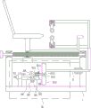
Fig. 1 is a schematic front view of the present invention.
Fig. 2 is a schematic front view of a placement block according to the present invention.
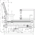
Fig. 3 is a schematic front view of the automatic traverse device of the present invention.
Fig. 4 is a first front view structural schematic diagram of the linked back automatic massage device of the invention.
Fig. 5 is a second front view of the automatic back massaging device of the present invention.
Fig. 6 is a left side view schematically showing the structure of the rotating ring of the present invention.
Fig. 7 is a front view schematically showing the structure of the wheel of the present invention.
In the figure: 1: bottom plate, 2: a bracket, 3: first slide rail, 4: first slider, 5: support plate, 6: seat board, 7: backup plate, 8: first nut, 9: first bearing seat, 10: screw rod, 11: crank, 12: first guide bush, 13: first guide rail, 14: support bar, 15: connecting rod, 16: extension rod, 17: first mounting sleeve, 18: first spring, 19: telescopic rod, 20: massage wheel, 101: mounting rod, 102: fixing rod, 103: placing block, 30: automatic back and forth device, 301: mounting block, 302: second slide rail, 303: second slider, 304: first screw, 305: second nut, 306: fixed block, 307: electric wheel, 308: turntable, 309: second mounting sleeve, 3010: rocker, 3011: threaded hole, 3012: second screw, 3013: third slide rail, 3014: third slider, 31: automatic back massage device with linkage 311: first L-shaped block, 312: first gear, 313: first bevel gear, 314: rack, 315: second bearing housing, 316: first rotating rod, 317: second bevel gear, 318: travel bar, 319: third bearing seat, 3110: rotating ring, 3111: second L-shaped block, 3112: fourth bearing seat, 3113: second rotating lever, 3114: runner, 3115: drive bar, 3116: reel, 3117: connecting block, 3118: second guide rail, 3119: second guide bush, 3120: second spring, 3121: bump, 3122: fixed pulley, 3123: stay wire, 3124: rectangular hole, 3125: canvas mesh, 3126: massage block, 3131: shaft seat, 3132: and (7) wheels.
Detailed Description
The preferred embodiments of the present invention will be described in detail with reference to the accompanying drawings.
Example 1
A leg and back massage device for medical care, as shown in figures 1-7, comprises a bottom plate 1, a support frame 2, a first slide rail 3, a first slide block 4, a support plate 5, a seat plate 6, a backup plate 7, a first nut 8, a first bearing seat 9, a screw rod 10, a crank 11, a first guide sleeve 12, a first guide rail 13, a support rod 14, a connecting rod 15, an extension rod 16, a first mounting sleeve 17, a first spring 18, an expansion rod 19 and a massage wheel 20, wherein the left side and the right side of the bottom plate 1 are connected with the support frame 2, the first slide rail 3 is connected between the upper inner sides of the support frame 2, the first slide rail 3 is connected with the first slide block 4 in a sliding way, the upper end of the first slide block 4 is connected with the support plate 5, the upper end of the support plate 5 is connected with the seat plate 6, the backup plate 7 is connected with the left side of the seat plate 6, the lower side of the front side of, lead screw 10 is connected in the first bearing frame 9, lead screw 10 passes first nut 8, lead screw 10 and the cooperation of first nut 8, lead screw 10 left end is connected with crank 11, 2 front sides middle parts of right side support are connected with first guide pin bushing 12, first guide pin bushing 12 internal sliding type is connected with first guide rail 13, right side top is connected with bracing piece 14 on the first guide rail 13, 14 upside rear sides of bracing piece are connected with connecting rod 15, both sides all are connected with extension rod 16 about connecting rod 15 left side, extension rod 16 left end all is connected with first installation cover 17, all be connected with first spring 18 in the first installation cover 17, first spring 18 inboard all is connected with telescopic link 19, the inboard equal rotation type of telescopic link 19 is connected with massage wheel 20.
Example 2
A leg and back massage device for medical care, as shown in figures 1-7, comprises a bottom plate 1, a support frame 2, a first slide rail 3, a first slide block 4, a support plate 5, a seat plate 6, a backup plate 7, a first nut 8, a first bearing seat 9, a screw rod 10, a crank 11, a first guide sleeve 12, a first guide rail 13, a support rod 14, a connecting rod 15, an extension rod 16, a first mounting sleeve 17, a first spring 18, an expansion rod 19 and a massage wheel 20, wherein the left side and the right side of the bottom plate 1 are connected with the support frame 2, the first slide rail 3 is connected between the upper inner sides of the support frame 2, the first slide rail 3 is connected with the first slide block 4 in a sliding way, the upper end of the first slide block 4 is connected with the support plate 5, the upper end of the support plate 5 is connected with the seat plate 6, the backup plate 7 is connected with the left side of the seat plate 6, the lower side of the front side of, lead screw 10 is connected in the first bearing frame 9, lead screw 10 passes first nut 8, lead screw 10 and the cooperation of first nut 8, lead screw 10 left end is connected with crank 11, 2 front sides middle parts of right side support are connected with first guide pin bushing 12, first guide pin bushing 12 internal sliding type is connected with first guide rail 13, right side top is connected with bracing piece 14 on the first guide rail 13, 14 upside rear sides of bracing piece are connected with connecting rod 15, both sides all are connected with extension rod 16 about connecting rod 15 left side, extension rod 16 left end all is connected with first installation cover 17, all be connected with first spring 18 in the first installation cover 17, first spring 18 inboard all is connected with telescopic link 19, the inboard equal rotation type of telescopic link 19 is connected with massage wheel 20.
The device is characterized by further comprising an installation rod 101, a fixing rod 102 and a placing block 103, wherein the installation rod 101 is connected to the lower portion of the right side of the supporting plate 5, the fixing rod 102 is connected to the right side of the upper side of the installation rod 101, and the placing block 103 is connected to the rear portion of the upper side of the fixing rod 102.
Example 3
A leg and back massage device for medical care, as shown in figures 1-7, comprises a bottom plate 1, a support frame 2, a first slide rail 3, a first slide block 4, a support plate 5, a seat plate 6, a backup plate 7, a first nut 8, a first bearing seat 9, a screw rod 10, a crank 11, a first guide sleeve 12, a first guide rail 13, a support rod 14, a connecting rod 15, an extension rod 16, a first mounting sleeve 17, a first spring 18, an expansion rod 19 and a massage wheel 20, wherein the left side and the right side of the bottom plate 1 are connected with the support frame 2, the first slide rail 3 is connected between the upper inner sides of the support frame 2, the first slide rail 3 is connected with the first slide block 4 in a sliding way, the upper end of the first slide block 4 is connected with the support plate 5, the upper end of the support plate 5 is connected with the seat plate 6, the backup plate 7 is connected with the left side of the seat plate 6, the lower side of the front side of, lead screw 10 is connected in the first bearing frame 9, lead screw 10 passes first nut 8, lead screw 10 and the cooperation of first nut 8, lead screw 10 left end is connected with crank 11, 2 front sides middle parts of right side support are connected with first guide pin bushing 12, first guide pin bushing 12 internal sliding type is connected with first guide rail 13, right side top is connected with bracing piece 14 on the first guide rail 13, 14 upside rear sides of bracing piece are connected with connecting rod 15, both sides all are connected with extension rod 16 about connecting rod 15 left side, extension rod 16 left end all is connected with first installation cover 17, all be connected with first spring 18 in the first installation cover 17, first spring 18 inboard all is connected with telescopic link 19, the inboard equal rotation type of telescopic link 19 is connected with massage wheel 20.
The device is characterized by further comprising an installation rod 101, a fixing rod 102 and a placing block 103, wherein the installation rod 101 is connected to the lower portion of the right side of the supporting plate 5, the fixing rod 102 is connected to the right side of the upper side of the installation rod 101, and the placing block 103 is connected to the rear portion of the upper side of the fixing rod 102.
The automatic back-and-forth device 30 also comprises an automatic back-and-forth device 30, the automatic back-and-forth device 30 comprises a mounting block 301, a second slide rail 302, a second slide block 303, a first screw 304, a second nut 305, a fixed block 306, an electric wheel 307, a rotary disc 308, a second mounting sleeve 309, a rocker 3010, a second screw 3012, a third slide rail 3013 and a third slide block 3014, the automatic back-and-forth device 30 is arranged on the left side of the first guide rail 13, the mounting block 301 is connected on the left side of the bottom plate 1, the second slide rail 302 is connected in the middle of the right side of the mounting block 301, the second slide block 303 is connected in the second slide rail 302 in a sliding manner, the lower end of the second slide block 303 is connected with the first screw 304, the second nut 305 is screwed on the first screw 304, the second nut 305 is matched with the first screw 304, the second nut 305 is fixed on the second slide block 303, the fixed block 306 is connected above the front side of, the right side of the rotary table 308 is connected with a second mounting sleeve 309, a rocker 3010 is placed in the second mounting sleeve 309, a threaded hole 3011 is formed in the right side of the upper side of the second mounting sleeve 309, a second screw 3012 is screwed in the threaded hole 3011, the second screw 3012 is matched with the threaded hole 3011, the rocker 3010 is fixed by the second screw 3012, the left end of the first guide rail 13 is connected with a third slide rail 3013, a third slide block 3014 is connected in the third slide rail 3013 in a sliding manner, and the right side of the front side of the rocker 3010 is hinged to the rear side of the third slide block 3014.
Example 4
A leg and back massage device for medical care, as shown in figures 1-7, comprises a bottom plate 1, a support frame 2, a first slide rail 3, a first slide block 4, a support plate 5, a seat plate 6, a backup plate 7, a first nut 8, a first bearing seat 9, a screw rod 10, a crank 11, a first guide sleeve 12, a first guide rail 13, a support rod 14, a connecting rod 15, an extension rod 16, a first mounting sleeve 17, a first spring 18, an expansion rod 19 and a massage wheel 20, wherein the left side and the right side of the bottom plate 1 are connected with the support frame 2, the first slide rail 3 is connected between the upper inner sides of the support frame 2, the first slide rail 3 is connected with the first slide block 4 in a sliding way, the upper end of the first slide block 4 is connected with the support plate 5, the upper end of the support plate 5 is connected with the seat plate 6, the backup plate 7 is connected with the left side of the seat plate 6, the lower side of the front side of, lead screw 10 is connected in the first bearing frame 9, lead screw 10 passes first nut 8, lead screw 10 and the cooperation of first nut 8, lead screw 10 left end is connected with crank 11, 2 front sides middle parts of right side support are connected with first guide pin bushing 12, first guide pin bushing 12 internal sliding type is connected with first guide rail 13, right side top is connected with bracing piece 14 on the first guide rail 13, 14 upside rear sides of bracing piece are connected with connecting rod 15, both sides all are connected with extension rod 16 about connecting rod 15 left side, extension rod 16 left end all is connected with first installation cover 17, all be connected with first spring 18 in the first installation cover 17, first spring 18 inboard all is connected with telescopic link 19, the inboard equal rotation type of telescopic link 19 is connected with massage wheel 20.
The device is characterized by further comprising an installation rod 101, a fixing rod 102 and a placing block 103, wherein the installation rod 101 is connected to the lower portion of the right side of the supporting plate 5, the fixing rod 102 is connected to the right side of the upper side of the installation rod 101, and the placing block 103 is connected to the rear portion of the upper side of the fixing rod 102.
The automatic back-and-forth device 30 also comprises an automatic back-and-forth device 30, the automatic back-and-forth device 30 comprises a mounting block 301, a second slide rail 302, a second slide block 303, a first screw 304, a second nut 305, a fixed block 306, an electric wheel 307, a rotary disc 308, a second mounting sleeve 309, a rocker 3010, a second screw 3012, a third slide rail 3013 and a third slide block 3014, the automatic back-and-forth device 30 is arranged on the left side of the first guide rail 13, the mounting block 301 is connected on the left side of the bottom plate 1, the second slide rail 302 is connected in the middle of the right side of the mounting block 301, the second slide block 303 is connected in the second slide rail 302 in a sliding manner, the lower end of the second slide block 303 is connected with the first screw 304, the second nut 305 is screwed on the first screw 304, the second nut 305 is matched with the first screw 304, the second nut 305 is fixed on the second slide block 303, the fixed block 306 is connected above the front side of, the right side of the rotary table 308 is connected with a second mounting sleeve 309, a rocker 3010 is placed in the second mounting sleeve 309, a threaded hole 3011 is formed in the right side of the upper side of the second mounting sleeve 309, a second screw 3012 is screwed in the threaded hole 3011, the second screw 3012 is matched with the threaded hole 3011, the rocker 3010 is fixed by the second screw 3012, the left end of the first guide rail 13 is connected with a third slide rail 3013, a third slide block 3014 is connected in the third slide rail 3013 in a sliding manner, and the right side of the front side of the rocker 3010 is hinged to the rear side of the third slide block 3014.
The automatic linked back massage device 31 further comprises an automatic linked back massage device 31, wherein the automatic linked back massage device 31 comprises a first L-shaped block 311, a first gear 312, a first bevel gear 313, a rack 314, a second bearing seat 315, a first rotating rod 316, a second bevel gear 317, a moving rod 318, a third bearing seat 319, a rotating ring 3110, a second L-shaped block 3111, a fourth bearing seat 3112, a second rotating rod 3113, a rotating wheel 3114, a driving rod 3115, a reel 3116, a connecting block 3117, a second guide rail 3118, a second guide sleeve 3119, a second spring 3120, a convex block 3121, a fixed pulley 3122, a pull wire 3123, a canvas mesh 3125 and a massage block 3126, the automatic linked back massage device 31 is arranged on the backup plate 7, the first L-shaped block 311 is connected to the right side of the lower side of the first sliding rail 3, the first gear 312 is connected to the left side of the first L-shaped block 311 in a rotary manner, the first bevel gear 313 is connected to the front side of the, the rack 314 is engaged with the first gear 312, a second bearing housing 315 is connected to the upper front side of the left bracket 2, a first rotating rod 316 is connected to the second bearing housing 315, a second bevel gear 317 is connected to the right end of the first rotating rod 316, the second bevel gear 317 is engaged with the first bevel gear 313, a moving rod 318 is connected to the left lower side of the seat 6, a third bearing housing 319 is connected to the lower end of the moving rod 318, a rotating ring 3110 is connected to the third bearing housing 319, the rotating ring 3110 is sleeved on the first rotating rod 316, the rotating ring 3110 is slidably connected to the first rotating rod 316 through the matching of a key groove and a key plate, a second L-shaped block 3111 is connected to the middle portion of the left side of the seat 6, a fourth bearing housing 3112 is connected to the lower end of the second L-shaped block 3112, a second rotating rod 3113 is connected to the fourth bearing housing 3112, rotating rods 3113 and rotating rings 3110 are connected to the outer sides, a rotating wheel 4 is connected to the driving, the upper portion of the left side of the seat plate 6 is connected with a connecting block 3117, the upper side of the connecting block 3117 is connected with a second guide rail 3118, the second guide rail 3118 is parallel to the backup plate 7, the second guide rail 3118 is connected with a second guide sleeve 3119 in a sliding mode, the lower side of the second guide sleeve 3119 is connected with a second spring 3120, the lower end of the second spring 3120 is connected to the lower side of the second guide rail 3118, the right side of the second guide sleeve 3119 is connected with a lug 3121, the upper portion of the left side of the second guide rail 3118 is connected with a fixed pulley 3122, the upper side of the second guide sleeve 3119 is connected with a pull wire 3123, the pull wire 3123 is connected to the reel 3116 through the upper side of the fixed pulley 3122, the backup plate 7 is provided with a rectangular hole 3124, the lug 3121 extends into the rectangular hole 3124, a.
The bicycle is characterized by further comprising a shaft seat 3131 and a wheel 3132, wherein the front side, the rear side, the left side and the right side of the lower side of the bottom plate 1 are both connected with the shaft seat 3131, and the lower side of the outer side of the shaft seat 3131 is rotatably connected with the wheel 3132.
When a user needs to massage the legs, the user can rotate the crank handle 11, the crank handle 11 drives the screw rod 10 to rotate, the screw rod 10 drives the first nut 8 to move left and right, the first nut 8 drives the supporting plate 5 to move left and right, thereby driving the seat plate 6 and the backup plate 7 to move left and right, so that the user sitting on the seat plate 6 can position the legs below the massage wheels 20, at the moment, the user can sit on the seat plate 6, then the leg is straightened so that the upper and lower sides of the leg are contacted with the massage wheel 20 and the first spring 18 is compressed, thereby the massage wheel 20 can be tightly attached to the leg of the user, then, another person can move the first guide rail 13 left and right, the first guide rail 13 drives the support rod 14 and the connecting rod 15 to move left and right, thereby driving the extension rod 16 and the first mounting sleeve 17 to move left and right, and driving the massage wheel 20 to move left and right, so that the massage wheel 20 can massage the upper and lower sides of the user's leg.
Because still including installation pole 101, dead lever 102 and place the piece 103, the backup pad 5 right side below is connected with installation pole 101, and the right-hand dead lever 102 that is connected with of installation pole 101 upside, dead lever 102 upside rear connection have place piece 103, when the user need place the shank and massage again, the user can place the shank and place and massage on placing piece 103, can give a stress point of shank like this.
Because the automatic back-and-forth device 30 is also included, the automatic back-and-forth device 30 comprises a mounting block 301, a second slide rail 302, a second slide block 303, a first screw 304, a second nut 305, a fixed block 306, an electric wheel 307, a rotary disc 308, a second mounting sleeve 309, a rocker 3010, a second screw 3012, a third slide 3013 and a third slide 3014, the automatic back-and-forth device 30 is arranged on the left side of the first guide rail 13, the mounting block 301 is connected on the left side of the bottom plate 1, the second slide rail 302 is connected in the middle of the right side of the mounting block 301, the second slide block 303 is connected in the second slide rail 302 in a sliding manner, the lower end of the second slide block 303 is connected with the first screw 304, the second nut 305 is screwed on the first screw 304, the second nut 305 is matched with the first screw 304, the second nut 305 fixes the second slide block 303, the fixed block 306 is connected above the front side of the second slide block 303, the electric wheel 307 is connected, the right side of the rotary table 308 is connected with a second mounting sleeve 309, a rocker 3010 is placed in the second mounting sleeve 309, the right side of the upper side of the second mounting sleeve 309 is provided with a threaded hole 3011, a second screw 3012 is screwed into the threaded hole 3011, the second screw 3012 is matched with the threaded hole 3011, the rocker 3010 is fixed by the second screw 3012, the left end of the first guide rail 13 is connected with a third slide 3013, the third slide 3013 is connected with a third slide 3014 in a sliding manner, the right side of the front side of the rocker 3010 is hinged to the rear side of the third slide 3014, when a user needs to automatically move the first guide rail 13 and the massage wheel 20 left and right, the user can start the electric wheel 307, the electric wheel 307 drives the rotary table 308 to rotate clockwise, the rotary table 308 drives the second mounting sleeve 309 and the rocker 3010 to rotate clockwise, the rocker 3010 drives the third slide 3014 to move upward in the third slide 3013, so that the rocker 3010 drives the third slide 3014 and the third slide 3013 to move left, when the rocking bar 3010 rotates to the right of the rotary table 308, the rocking bar 3010 drives the third sliding rail 3013 and the third sliding block 3014 to move rightwards, thereby driving the first guide rail 13 and the massage wheel 20 to move rightwards, so that the massage wheel 20 moves back and forth to massage the legs, when the user desires to massage the leg to a greater or lesser extent, the user may turn off the motorized wheel 307, the user may then rotate the second screw 3012 and the second nut 305, such that the second screw 3012 no longer secures the rocker 3010, such that the second nut 305 no longer secures the second slider 303, then the user can move the second sliding block 303 left and right, the second sliding block 303 drives the fixed block 306, the electric wheel 307, the rotary disc 308 and the second installation sleeve 309 to move left and right, so that the length of the rocker 3010 extending out of the second mounting sleeve 309 is changed, thereby changing the rotating radius of the rocker 3010 and the turntable 308, thereby changing the rotation radius of the third slide rail 3013 and the moving distance of the first guide rail 13.
Because the linked back automatic massage device 31 is further included, the linked back automatic massage device 31 includes a first L-shaped block 311, a first gear 312, a first bevel gear 313, a rack 314, a second bearing housing 315, a first rotating rod 316, a second bevel gear 317, a moving rod 318, a third bearing housing 319, a rotating ring 3110, a second L-shaped block 3111, a fourth bearing housing 3112, a second rotating rod 3113, a rotating wheel 3114, a driving bar 3115, a reel 3116, a connecting block 3117, a second guide rail 3118, a second guide sleeve 3119, a second spring 3120, a bump 3121, a fixed pulley 3122, a pull wire 3123, a canvas mesh 3125 and a massage block 3126, the linked back automatic massage device 31 is provided on the backup plate 7, the right side of the lower side of the first sliding rail 3 is connected with the first L-shaped block 311, the left side of the front side of the first L-shaped block 311 is connected with the first gear 312, the front side of the first gear 312 is connected with the first bevel gear 313, the upper side of, the rack 314 is engaged with the first gear 312, a second bearing housing 315 is connected to the upper front side of the left bracket 2, a first rotating rod 316 is connected to the second bearing housing 315, a second bevel gear 317 is connected to the right end of the first rotating rod 316, the second bevel gear 317 is engaged with the first bevel gear 313, a moving rod 318 is connected to the left lower side of the seat 6, a third bearing housing 319 is connected to the lower end of the moving rod 318, a rotating ring 3110 is connected to the third bearing housing 319, the rotating ring 3110 is sleeved on the first rotating rod 316, the rotating ring 3110 is slidably connected to the first rotating rod 316 through the matching of a key groove and a key plate, a second L-shaped block 3111 is connected to the middle portion of the left side of the seat 6, a fourth bearing housing 3112 is connected to the lower end of the second L-shaped block 3112, a second rotating rod 3113 is connected to the fourth bearing housing 3112, rotating rods 3113 and rotating rings 3110 are connected to the outer sides, a rotating wheel 4 is connected to the driving, a connecting block 3117 is connected above the left side of the seat plate 6, a second guide rail 3118 is connected above the connecting block 3117, the second guide rail 3118 is parallel to the backup plate 7, a second guide sleeve 3119 is connected on the second guide rail 3118 in a sliding manner, a second spring 3120 is connected below the second guide sleeve 3119, the lower end of the second spring 3120 is connected below the second guide rail 3118, a projection 3121 is connected on the right side of the second guide sleeve 3119, a fixed pulley 3122 is connected above the left side of the second guide rail 3118, a pull wire 3123 is connected above the second guide sleeve 3119, the pull wire 3123 is connected on the reel 3116 through the upper side of the fixed pulley 3122, a rectangular hole 3124 is opened on the backup plate 7, the projection 3121 extends into the rectangular hole 3124, a canvas net 3125 is connected between the upper wall and the lower wall of the rectangular hole 3124 of the backup plate 7, massage blocks 3126 are uniformly distributed on the right side of the canvas net 3125, when a user needs to automatically massage the back, the moving rod 318 drives the third bearing housing 319 and the rotating ring 3110 to move left and right, the rotating ring 3110 moves left and right through the matching of the key slot and the key plate, then the user can start the electric wheel 307, the electric wheel 307 drives the first guide rail 13 to move left and right, the first guide rail 13 drives the rack 314 to move left and right, the rack 314 drives the first gear 312 to rotate, the first gear 312 drives the first rotating rod 316 through the first bevel gear 313 and the second bevel gear 317, the first rotating rod 316 drives the rotating ring 3110 to rotate through the matching of the key slot and the key plate, the rotating ring 3110 drives the lower rotating wheel 3114 to rotate, so as to drive the upper rotating wheel 3114 to rotate through the driving bar 3115, the upper rotating rod 3113 drives the second rotating rod 3113 to rotate, the second rotating rod 3113 drives the reel 3116 to rotate, the reel 3116 will recover the stay wire 3123 at this time, the stay 3123 will drive the second guide sleeve 3129 to move up through the fixed, the second guide sleeve 3119 drives the projection 3121 to move upward, so that the projection 3121 contacts the canvas mesh 3125, so that the projection 3121 moves the massage block 3126 to the right side, so that the massage block 3126 massages the back of the user, because the rack 314 moves left and right, when the rack 314 drives the first gear 312 to rotate reversely, the reel 3116 also rotates reversely to loosen the pull wire 3123, at this time, the second spring 3120 recovers from the stretching state, so that the second guide sleeve 3119 and the projection 3121 are driven to move downward, so that the projection 3121 moves downward to massage the massage block 3126 to massage the back of the user, and after the massage is completed, the user can close the electric wheel 307.
Since the device further comprises a shaft seat 3131 and a wheel 3132, the shaft seat 3131 is connected to the front and rear sides of the lower side of the base plate 1, and the wheel 3132 is rotatably connected to the lower side of the outer side of the shaft seat 3131, when a user needs to move the device quickly, the user can move the device via the wheel 3132.
The above-mentioned embodiments are merely preferred embodiments of the present invention, which are not intended to limit the scope of the present invention, and therefore, all equivalent changes made by the contents of the claims of the present invention should be included in the claims of the present invention.