CN108475552B - Composites for high frequency electromagnetic interference (EMI) applications - Google Patents
Composites for high frequency electromagnetic interference (EMI) applications Download PDFInfo
- Publication number
- CN108475552B CN108475552B CN201680076781.XA CN201680076781A CN108475552B CN 108475552 B CN108475552 B CN 108475552B CN 201680076781 A CN201680076781 A CN 201680076781A CN 108475552 B CN108475552 B CN 108475552B
- Authority
- CN
- China
- Prior art keywords
- particles
- article
- silsesquioxane
- based particles
- ssq
- Prior art date
- Legal status (The legal status is an assumption and is not a legal conclusion. Google has not performed a legal analysis and makes no representation as to the accuracy of the status listed.)
- Active
Links
Images


Classifications
-
- H—ELECTRICITY
- H05—ELECTRIC TECHNIQUES NOT OTHERWISE PROVIDED FOR
- H05K—PRINTED CIRCUITS; CASINGS OR CONSTRUCTIONAL DETAILS OF ELECTRIC APPARATUS; MANUFACTURE OF ASSEMBLAGES OF ELECTRICAL COMPONENTS
- H05K9/00—Screening of apparatus or components against electric or magnetic fields
- H05K9/0073—Shielding materials
- H05K9/0081—Electromagnetic shielding materials, e.g. EMI, RFI shielding
- H05K9/0083—Electromagnetic shielding materials, e.g. EMI, RFI shielding comprising electro-conductive non-fibrous particles embedded in an electrically insulating supporting structure, e.g. powder, flakes, whiskers
-
- C—CHEMISTRY; METALLURGY
- C08—ORGANIC MACROMOLECULAR COMPOUNDS; THEIR PREPARATION OR CHEMICAL WORKING-UP; COMPOSITIONS BASED THEREON
- C08K—Use of inorganic or non-macromolecular organic substances as compounding ingredients
- C08K3/00—Use of inorganic substances as compounding ingredients
- C08K3/02—Elements
- C08K3/04—Carbon
- C08K3/041—Carbon nanotubes
-
- H—ELECTRICITY
- H01—ELECTRIC ELEMENTS
- H01B—CABLES; CONDUCTORS; INSULATORS; SELECTION OF MATERIALS FOR THEIR CONDUCTIVE, INSULATING OR DIELECTRIC PROPERTIES
- H01B1/00—Conductors or conductive bodies characterised by the conductive materials; Selection of materials as conductors
- H01B1/20—Conductive material dispersed in non-conductive organic material
- H01B1/22—Conductive material dispersed in non-conductive organic material the conductive material comprising metals or alloys
-
- H—ELECTRICITY
- H01—ELECTRIC ELEMENTS
- H01B—CABLES; CONDUCTORS; INSULATORS; SELECTION OF MATERIALS FOR THEIR CONDUCTIVE, INSULATING OR DIELECTRIC PROPERTIES
- H01B1/00—Conductors or conductive bodies characterised by the conductive materials; Selection of materials as conductors
- H01B1/20—Conductive material dispersed in non-conductive organic material
- H01B1/24—Conductive material dispersed in non-conductive organic material the conductive material comprising carbon-silicon compounds, carbon or silicon
-
- H—ELECTRICITY
- H05—ELECTRIC TECHNIQUES NOT OTHERWISE PROVIDED FOR
- H05K—PRINTED CIRCUITS; CASINGS OR CONSTRUCTIONAL DETAILS OF ELECTRIC APPARATUS; MANUFACTURE OF ASSEMBLAGES OF ELECTRICAL COMPONENTS
- H05K9/00—Screening of apparatus or components against electric or magnetic fields
- H05K9/0073—Shielding materials
- H05K9/0081—Electromagnetic shielding materials, e.g. EMI, RFI shielding
- H05K9/009—Electromagnetic shielding materials, e.g. EMI, RFI shielding comprising electro-conductive fibres, e.g. metal fibres, carbon fibres, metallised textile fibres, electro-conductive mesh, woven, non-woven mat, fleece, cross-linked
-
- H—ELECTRICITY
- H10—SEMICONDUCTOR DEVICES; ELECTRIC SOLID-STATE DEVICES NOT OTHERWISE PROVIDED FOR
- H10W—GENERIC PACKAGES, INTERCONNECTIONS, CONNECTORS OR OTHER CONSTRUCTIONAL DETAILS OF DEVICES COVERED BY CLASS H10
- H10W42/00—Arrangements for protection of devices
- H10W42/20—Arrangements for protection of devices protecting against electromagnetic or particle radiation, e.g. light, X-rays, gamma-rays or electrons
- H10W42/281—Arrangements for protection of devices protecting against electromagnetic or particle radiation, e.g. light, X-rays, gamma-rays or electrons characterised by their materials
- H10W42/284—Arrangements for protection of devices protecting against electromagnetic or particle radiation, e.g. light, X-rays, gamma-rays or electrons characterised by their materials shielding resins
Landscapes
- Chemical & Material Sciences (AREA)
- Physics & Mathematics (AREA)
- Engineering & Computer Science (AREA)
- Spectroscopy & Molecular Physics (AREA)
- Dispersion Chemistry (AREA)
- Electromagnetism (AREA)
- Microelectronics & Electronic Packaging (AREA)
- Health & Medical Sciences (AREA)
- Nanotechnology (AREA)
- Chemical Kinetics & Catalysis (AREA)
- Medicinal Chemistry (AREA)
- Polymers & Plastics (AREA)
- Organic Chemistry (AREA)
- Materials Engineering (AREA)
- Textile Engineering (AREA)
- Compositions Of Macromolecular Compounds (AREA)
- Shielding Devices Or Components To Electric Or Magnetic Fields (AREA)
Abstract
本发明描述了电磁干扰(EMI)屏蔽制品及其制造和使用该EMI屏蔽制品的方法。该制品包括分布在聚合物基体材料内的导电填料和倍半硅氧烷类(SSQ类)粒子。在一些情况下,添加SSQ类粒子导致制品的孔隙度增加,这改善EMI吸收性能。
The present invention describes electromagnetic interference (EMI) shielding articles and methods of making and using the same. The article includes a conductive filler and silsesquioxane-type (SSQ-type) particles distributed within a polymer matrix material. In some cases, the addition of SSQ-type particles results in an increase in the porosity of the article, which improves EMI absorption performance.
Description
Technical Field
The present disclosure relates to composites or articles for high frequency electromagnetic interference (EMI) applications and methods of making the composites or articles.
Background
Electromagnetic interference (EMI) shielding of electronic devices and/or radiation sources is an important consideration in the reliable operation of the devices. EMI shielding may be achieved by reflection of Electromagnetic (EM) waves, absorption of waves, or both. It is most common to use highly conductive metal foils (known as EM cages) to reflect the unwanted EM waves. However, in some cases, merely reflecting the EM waves is not sufficient or may cause additional problems. This leads to the need to provide EMI absorbers and shielding materials and methods for absorbing EM waves, particularly in the high frequency range, e.g., 1Hz to 40GHz or 1GHz to 100GHz, and harmonics associated with such fundamental frequencies.
Disclosure of Invention
Briefly, in one aspect, the present disclosure describes an electromagnetic interference (EMI) shielding article that includes an electrically-conductive filler, silsesquioxane-based (SSQ-based) particles, and a polymeric matrix material. The conductive filler and the SSQ-like particles are distributed within the polymer matrix material. In some embodiments, the composition of the article comprises about 25 wt.% or less, 15 wt.% or less, 5 wt.% or less, 3 wt.% or less, or 1 wt.% or less of the SSQ-based particles.
In another aspect, the present disclosure describes a method of making an EMI shielding article. The method includes providing a conductive filler, providing silsesquioxane-based (SSQ-based) particles, and adding a mixture of the conductive filler and the SSQ-based particles to a polymeric matrix material. The conductive filler and the SSQ-like particles are distributed within the polymer matrix material. In some embodiments, the conductive filler comprises a Carbon Nanostructure (CNS) filler comprising crosslinked carbon nanotubes.
Various unexpected results and advantages are achieved in exemplary embodiments of the present disclosure. One such advantage of exemplary embodiments of the present disclosure is that the EMI shielding article exhibits excellent EMI absorber performance by incorporating small amounts (e.g., about 25 wt.% or less, 15 wt.% or less, 5 wt.% or less, about 3 wt.% or less, about 1 wt.% or less, or even about 0.5 wt.% or less) of SSQ-like nanoparticles in the polymer matrix.
Various aspects and advantages of exemplary embodiments of the present disclosure have been summarized. The above summary is not intended to describe each illustrated embodiment or every implementation of the present certain exemplary embodiments of the present disclosure. The following drawings and detailed description more particularly exemplify certain preferred embodiments using the principles disclosed herein.
Drawings
The disclosure may be more completely understood in consideration of the following detailed description of various embodiments of the disclosure in connection with the accompanying drawings, in which:
fig. 1 shows a schematic model of an SSQ-like particle aggregate.
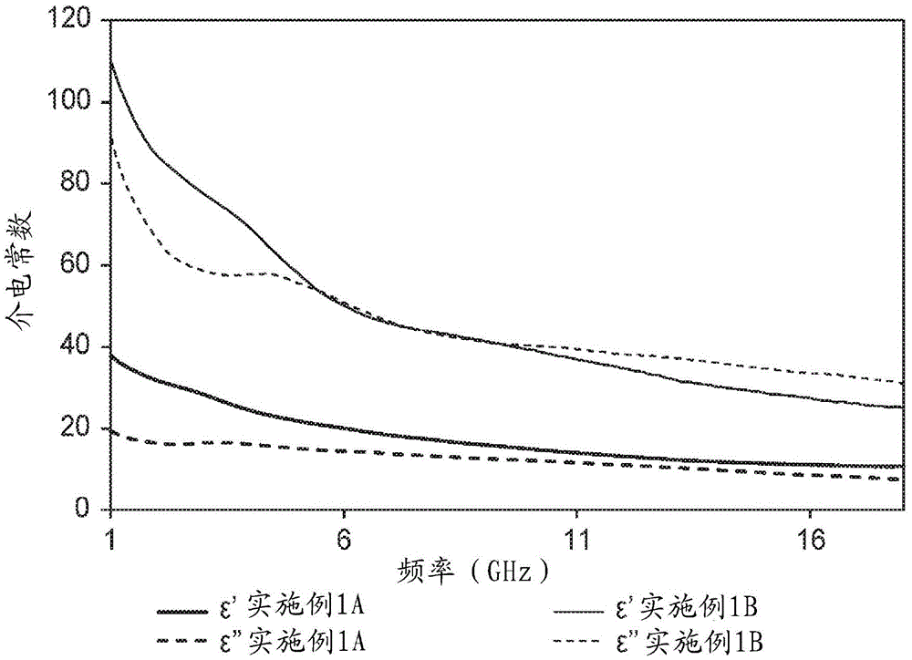
FIG. 2A shows the results of testing examples 1A and 1B showing plots of real and imaginary parts of the dielectric constant versus frequency for the polymeric composite.
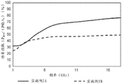
Fig. 2B shows the test results of examples 1A and 1B showing a plot of Electromagnetic (EM) power absorbed by the polymeric composite versus frequency.
Figure 3 shows the results of testing examples 2A and 2B showing plots of the real and imaginary parts of the dielectric constant of the polymeric composite versus frequency.
In the drawings, like numbering represents like elements. While the above-identified drawing figures, which may not be drawn to scale, illustrate various embodiments of the disclosure, other embodiments are also contemplated, as noted in the detailed description. In all cases, this disclosure describes the presently disclosed disclosure by way of representation of exemplary embodiments and not by express limitations. It should be understood that numerous other modifications and embodiments can be devised by those skilled in the art, which fall within the scope and spirit of the disclosure.
Detailed Description
For the glossary of defined terms below, these definitions shall prevail throughout the application, unless a different definition is provided in the claims or elsewhere in the specification.
Glossary
Certain terms are used throughout the description and claims, and although mostly known, some explanation may be required. It should be understood that:
the term "homogeneous" means exhibiting only a single phase of matter when viewed on a macroscopic scale.
The term "(co) polymer" includes homopolymers and copolymers, as well as homopolymers or copolymers that may be formed, for example, by coextrusion or by reaction (including, for example, transesterification) in a miscible blend. The term "copolymer" includes random copolymers, block copolymers, and star (e.g., dendritic) copolymers.
The term "carbon nanostructure" or "CNS" refers to Carbon Nanotubes (CNTs) organized in a cross-linked network.
The term "polymeric encapsulation material" refers to a polymeric material that at least partially encapsulates CNTs.
The term "curable matrix material" refers to a polymeric material that is capable of being cured thermally or by light and which, after curing, forms a cured polymeric body that serves as a matrix to carry fillers or additives embedded therein.
The term "silsesquioxane" or "SSQ" refers to a siloxane of the formula RSiO3/2An organic and inorganic mixture characterized wherein R represents an organic substituent wherein silicon atoms are linked together by an oxygen atom and the R group is linked to the silicon atom, the Si-O group provides the inorganic character and the R group provides the organic character.
The term "silsesquioxane-like" or "SSQ-like" particles is meant to include particles having the general formula (RHSiO)n-(RSiO3/2)mWherein R represents an organic substituent wherein the silicon atoms are linked together by an oxygen atom and the R group is linked to the silicon atoms, the Si-O group provides the inorganic character and the R group provides the organic character.
The term "about" or "approximately" with respect to a numerical value or shape means +/-5% of the numerical value or attribute or characteristic, but expressly includes the exact numerical value. For example, a viscosity of "about" 1Pa-sec refers to a viscosity of 0.95Pa-sec to 1.05Pa-sec, but also specifically includes a viscosity of exactly 1 Pa-sec. Similarly, a perimeter of "substantially square" is intended to describe a geometric shape having four lateral edges, wherein the length of each lateral edge is 95% to 105% of the length of any other lateral edge, but also includes geometric shapes wherein each lateral edge has exactly the same length.
The term "substantially" with respect to an attribute or feature means that the attribute or feature exhibits a greater degree of expression than does the opposite side of the attribute or feature. For example, a substrate that is "substantially" transparent refers to a substrate that transmits more radiation (e.g., visible light) than it does not. Thus, a substrate that transmits more than 50% of visible light incident on its surface is substantially transparent, but a substrate that transmits 50% or less of visible light incident on its surface is not substantially transparent.
As used in this specification and the appended embodiments, the singular forms "a", "an", and "the" include plural referents unless the content clearly dictates otherwise. Thus, for example, reference to a fine fiber comprising "a compound" includes a mixture of two or more compounds. As used in this specification and the appended embodiments, the term "or" is generally employed in its sense including "and/or" unless the content clearly dictates otherwise.
As used in this specification, the recitation of numerical ranges by endpoints includes all numbers subsumed within that range (e.g. 1 to 5 includes 1, 1.5, 2, 2.75, 3, 3.8, 4, and 5).
Unless otherwise indicated, all numbers expressing quantities or ingredients, measurement of properties, and so forth used in the specification and embodiments are to be understood as being modified in all instances by the term "about". Accordingly, unless indicated to the contrary, the numerical parameters set forth in the foregoing specification and attached list of embodiments may vary depending upon the desired properties sought to be obtained by those skilled in the art utilizing the teachings of the present disclosure. At the very least, and not as an attempt to limit the application of the doctrine of equivalents to the scope of the claimed embodiments, each numerical parameter should at least be construed in light of the number of reported significant digits and by applying ordinary rounding techniques.
The present disclosure describes electromagnetic interference (EMI) shielding articles having a composition comprising an electrically conductive filler, silsesquioxane-based (SSQ-based) particles, and a polymer matrix material for distributing the filler and particles. In some embodiments, the composition is capable of absorbing at least a portion of incident Electromagnetic (EM) energy at fundamental frequencies and their harmonics in the range of 0.1 to 40 GHz. In some embodiments, the SSQ-like particles added to the composition are capable of increasing the EM energy absorption of the composition by at least 5% over the fundamental frequency range of 0.1 to 40GHz and its harmonics, as compared to a composition without the SSQ-like particles.
A Carbon Nanostructure (CNS) -encapsulating sheet is a form of Carbon Nanotubes (CNTs) that includes a cross-linked multi-walled carbon nanotube-based network of the CNS. In some embodiments, the carbon nanotubes of the CNS encapsulation sheet can be compounded by various polymeric encapsulation materials, such as Polyurethane (PU), polyethylene glycol (PEG), Polyamide (PA), and the like. In the CNS encapsulating sheet, the carbon nanotubes may be at least partially encapsulated by one or more polymeric encapsulating materials. In some embodiments, about 50% or more, about 70% or more, about 90% or more, or about 95% or more of the surface area of the crosslinked network of carbon nanotubes can be covered by the polymeric encapsulation material. In some embodiments, the CNS flake can comprise, for example, from about 1% to about 20%, from about 2% to about 10%, or from about 3% to about 5% by weight of the polymeric encapsulating material.
The CNTs in the CNS-encapsulated sheet can exhibit metallic or semiconducting behavior with a range of resistivities, e.g., about 1 x 10 resistivity at room temperature-8To about 1X 10⁻²Omega-cm. CNTs can have desirable electromagnetic absorption properties, such as the ability to absorb electromagnetic radiation and dissipate absorbed energy in the host polymer matrix. The polymer encapsulating material may be electrically insulating over a range of resistivity, for example, about 1 x 10 2To about 1X 10²⁰Ω-cm。
In some embodiments, CNS encapsulating flakes can be dispersed in a curable matrix material to form a composite that can impart EMI absorbing properties from CNTs dispersed therein. The formed composite may comprise, for example, from about 0.05 to about 10 wt%, from about 0.1 to about 5 wt%, or from about 0.2 to about 2 wt% of a CNS filler, such as a CNS encapsulating flake or powder. The composite may include, for example, about 5 wt% or less, about 3 wt% or less, about 1 wt% or less, or even about 0.5 wt% or less of the CNS fillers to exhibit the desired EMI absorbing characteristics. The curable matrix material may include, for example, epoxy, silicone, polycarbonate, polyester, polyurethane resins, and the like. The curable matrix material may be cured, for example, by radiation or heat, to form a radiation cured polymer body or a thermally cured polymer body.
In some embodiments, the CNS encapsulating sheet can have an average length of from about 10 microns to about 500 microns and an average thickness of from about 1 micron to about 50 microns. In some embodiments, the CNS-encapsulating lamellae may be ground to a fine powder prior to dispersion in a curable matrix material to form the EMI shielding composite. The mean diameter of the CNS fine powder can be in a range, for example, from about 0.1 microns to about 10 microns, or from about 0.5 microns to about 5 microns. It is understood that the milling process can reduce the size of the particles without changing the micro-scale CNS encapsulation structure.
In some embodiments described herein, the EMI shielding composite may also include silsesquioxane-based (SSQ-based) particles. Exemplary silsesquioxane-based particles and methods for their preparation are described in WO 2014/003827(rathe et al), which is incorporated herein by reference. Silsesquioxanes are organic hybrids and inorganic hybrids. The silsesquioxanes are characterized by the general formula RSiO3/2Wherein R represents an organic substituent. The silicon atoms are linked together by an oxygen atom and the R group is attached to the silicon atom. The Si-O groups provide inorganic character, while the R groups provide organic character.
The silsesquioxane-based particles of the present disclosure may be derived from a polyalkylene siloxane and a water-soluble base that are contacted to form the particles of the present disclosure.
Polyhydrosiloxanes are polymers represented by the formula:

wherein Z1And Z2Is an end group; n is an integer greater than 2; and R is an organic group.
The end groups of formula I are derived from the starting materials used for preparing the polyhydrosiloxanes. These end groups are not particularly limited and may include, for example, alkylated (linear, cyclic, or branched) silanes. Exemplary end groups include:
-Si(CH3)3、-Si(CH3)2H、-Si(CH3)H2、-Si(CH2CH3)3、-Si(CH2CH2CH2CH3)3、-Si(C(CH3)3)3、-Si(CH2CH(CH3)CH3)3and-Si (CH)3)CH2CH3)3。
The polyhydrosiloxane includes repeating units, wherein n is at least 2, 4, 5, 6, 8, 10, 25, 50, 75, 100, 150, or even 200; and up to 1000, 2500, 5000, 7500, 10000 or even 15000.
R is an organic group which may be linear or branched, cyclic or acyclic, saturated or unsaturated. The organic group may contain as few as 1, 2, 3, 4, 5, 6, 7, 8, or even 9 carbon atoms and as many as 15, 17, 20, 25, 30, or even 35 carbon atoms. As used herein, "organic group" refers to a carbon-based group attached through a carbon atom. In one embodiment, the organic group may comprise one or more functional groups, such as amine, ammonium, ether, ester, or carbamate groups.
In one embodiment, the organic group is unsubstituted. In one embodiment, the organic group is an alkyl group. Exemplary alkyl groups include methyl, ethyl, propyl, butyl, octyl, and phenyl.
In another embodiment, the organic group is substituted (i.e., the organic group contains at least one atom other than carbon and hydrogen). In one embodiment, the substituted organic group comprises at least one catenated heteroatom (e.g., O, S and/or N) and/or halogen (e.g., Cl, Br, and/or I).
Exemplary organic groups include: methyl, ethyl, propyl, butyl, C6H4Y-、C6H5(CH2)-、C6H5(CH2)-、C6H5(CHY) -and C6H5(CY2) Wherein Y can be chlorine, bromine, iodine, alkoxy, or combinations thereof, and alkyl (CH) 2=CH-R1-) and vinyl (CH)2=CR1-) group, wherein R1Is straight chain or branchedA chained alkyl group.
Exemplary hydrogenpolysiloxanes can include: polymethylhydrosiloxane, polyethylhydrosiloxane, polypropylhydrosiloxane, polybutylhydrosiloxane, polybenzylhydrosiloxane, methylhydrocyclosiloxane, and combinations thereof.
The polyhydrosiloxane can have at least 500, 1000, 1500, 1800, 2000, 2400, or even 2500 grams/mole; and a weight average molecular weight of at most 5000 g/mole, 10000 g/mole, 15000 g/mole, 20000 g/mole, 25000 g/mole, 30000 g/mole or even 60000 g/mole.
In some embodiments, the obtained SSQ-based particles may have an average particle size of, for example, not less than about 5nm, not less than 10nm, or not less than 20 nm. In some embodiments, the SSQ-based particles may have an average particle size, for example, of no greater than about 1 micron, no greater than 500nm, no greater than 200nm, or no greater than 100 nm. In some embodiments, the average size of the SSQ-based particles may be in a range from, for example, about 10nm to about 500 nm.
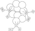
In some embodiments, the SSQ-based particles may further agglomerate or aggregate together to form agglomerates or aggregates having an average size of, for example, not less than about 500nm, not less than 1 micron, or not less than 2 microns. The average size of the SSQ-like particle aggregates can be, for example, not greater than about 50 microns, not greater than 20 microns, not greater than 10 microns, or not greater than 5 microns. In some embodiments, the average size of the agglomerates or aggregates may range from about 1 micron to about 10 microns. Fig. 1 shows an exemplary SSQ-like particle aggregate.
As shown in fig. 1, when the SSQ-based particles of the present disclosure are aggregated, the generally spherical particles are bonded together to form the aggregate. Typically, the particles are chain-like, meaning that they are joined together to form a string of particles. While not wishing to be bound by theory, it is believed that the particles are covalently bonded together through the reaction of a given polymer chain in two distinct particles. Such aggregates may include at least two individual substantially spherical particles. In one embodiment, it is believed that the aggregate may result in improved performance in some applications, such as in high strength composites. When the SSQ-like particles of the present disclosure are aggregates of primary nanoparticle-sized sirtuin particles, the maximum cross-sectional dimension of the aggregated particles may be, for example, greater than 10nm, 100nm, 200nm, 500nm, or even 1000 nm.
In some embodiments, the SSQ-based particles of the present disclosure have a high specific surface area. For example, it is at least 50m based on BET (Brunaue Emmet Teller method) nitrogen adsorption2/g、200m2/g、400m2A/g, or even 500m2(ii)/g; it is up to 1000m2/g、1200m2/g、1400m2/g、1500m2A/g, or even 1800m2/g。
In some embodiments, the SSQ-like particles of the present disclosure are thermally stable, meaning that they can be heated to at least 120 ℃, 130 ℃, 140 ℃, 150 ℃, 160 ℃, 170 ℃, 180 ℃, or even to 200 ℃; they can be heated up to 250 ℃, 275 ℃, 300 ℃, 325 ℃, 350 ℃, 400 ℃, 500 ℃, 600 ℃, 700 ℃, or even to 800 ℃ and achieve a weight loss of less than 15%.
In the present disclosure, EMI composites can exhibit excellent EMI absorber performance (e.g., a significantly reduced real part of the dielectric constant value) by incorporating a small amount of SSQ-based nanoparticles in a polymer matrix. The EMI shielding composites described herein can comprise, for example, from about 0.005 wt.% to about 10 wt.%, from about 0.01 wt.% to about 5 wt.%, or from about 0.25 wt.% to about 2 wt.% of the SSQ-based particles. The EMI shielding composite can include, for example, about 5 wt.% or less, about 3 wt.% or less, about 1 wt.% or less, or even about 0.5 wt.% or less of SSQ-type particles to exhibit desired EMI absorbing properties.
While not wishing to be bound by theory, it is believed that the added SSQ-like particles may result in an inherent porosity in the composite, and this may result in lower values of the real and imaginary parts of the dielectric constant (i.e., values of ∈' and ∈ ″) as compared to a composite without SSQ-like particles. SSQ-based particles include Si-H groups that can generate hydrogen when reacted with amines from a polymer matrix material, such as epoxy resins. Hydrogen bubbles generated in the composite can lead to its inherent porosity.
The added SSQ-like particles are chemically compatible with the curable matrix material to be mixed. For example, the viscosity of the curable matrix material may remain substantially unchanged when mixed with the SSQ-based particle aggregates.
In some embodiments, the EMI shielding composites described herein may also include magnetic fillers and/or dielectric fillers. Mixtures of CNS fillers, SSQ-like particles, and other fillers may be dispersed in a curable matrix material to form an EMI shielding composite. The composition of the formed EMI shielding composite may include, for example, from about 30 wt.% to about 90 wt.%, or from about 50 wt.% to about 80 wt.%, of the magnetic filler and/or the dielectric filler. The magnetic filler may include, for example, ferromagnetic or ferrimagnetic materials including doped or undoped Carbonyl Iron Powder (CIP), iron silicide, ceramic magnetic ferrite, ceramic magnetic garnet, or combinations thereof. Suitable dispersing agents may be added during mixing. The dielectric filler may include, for example, doped or undoped TiO, CuO, SiC, or mixtures thereof.
In some embodiments, the EMI shielding composite may further include a multiferroic filler, such as BiFeO, in an amount of, for example, about 30 wt.% to about 90 wt.%, or about 50 wt.% to about 80 wt.%3、BiMnO3Or mixtures thereof.
The present disclosure provides methods of making EMI shielding composites that include small amounts of SSQ-like particles. The EMI shielding composites in the present disclosure use Carbon Nanostructure (CNS) fillers as the conductive filler. The CNS fillers can include, for example, CNS encapsulating flakes or powders as described above. The present disclosure also provides methods of modulating the properties of EMI shielding composites by treating CNS fillers. In some embodiments, the CNS fillers can be treated to at least partially remove the polymeric encapsulation material therefrom. It should be appreciated that other suitable conductive fillers may also be used, such as carbon black, carbon foam, carbon fiber, expanded graphite, graphene nanoflakes, metal nanoparticles, metal alloy particles, metal nanowires, conductive coated particles, combinations thereof, or the like.
CNS fillers provided herein can include a crosslinked network of carbon nanotubes and a polymeric encapsulation material. The CNS fillers can be, for example, CNS encapsulating flakes or powders comprising a plurality of cross-linked and entangled carbon nanotubes, and one or more polymeric encapsulating materials. The carbon nanotubes may be at least partially encapsulated by one or more polymeric encapsulating materials. CNS encapsulated flakes can be ground to a fine powder of reduced size or size without altering the microstructure.
In some embodiments, the CNS fillers can be treated to remove at least a portion of the polymeric encapsulation material. After removing the polymer encapsulation material, the carbon nanotubes may be at least partially exposed. In some embodiments, 50 wt% or more, 70 wt% or more, 90 wt% or more, 99 wt% or more, or 99.9 wt% or more of the polymeric encapsulation material may be removed from the CNS fillers. In some embodiments, the CNS fillers can be treated with a suitable solvent to dissolve and separate the corresponding polymeric encapsulation material from the carbon nanotubes. In some embodiments, the polymeric encapsulation material may include polyethylene glycol (PEG), and the solvent may include water that dissolves the PEG encapsulation. In some embodiments, the polymeric encapsulation material may include Polyurethane (PU), and the solvent may include N, N-Dimethylacetamide (DMF) that dissolves PU encapsulation. In some embodiments, the polymeric encapsulating material may include a polyamide, and the solvent may include ethanol that dissolves the polyamide encapsulation. It should be appreciated that the polymeric encapsulation material may include other types of polymers, and one or more suitable solvents may be used to dissolve the corresponding polymeric encapsulation material, thereby removing the polymeric encapsulation material from the CNS fillers. Method 100 then proceeds to 130.
In the present disclosure, SSQ-based particles are introduced to be mixed with treated or untreated CNS fillers, and if desired, also with other fillers. The mixture is then added to a curable matrix material to obtain an electromagnetic interference (EMI) shielding composite. In some embodiments, the matrix material may include a curable polymeric material, such as an epoxy, silicone, polycarbonate, polyester, polyurethane resin, or the like. The EMI shielding filmThe compound may comprise, for example, 0.05 to 10 wt%, 0.1 to 5 wt%, or 0.25 to 2 wt% CNS filler. The CNS filler may be, for example, about 0.1g/cm3To about 25g/cm3About 0.3g/cm3To about 10g/cm3Or about 0.5g/cm3To about 5.0g/cm3Is dispersed in the curable matrix material. In some embodiments, the CNS fillers can be uniformly dispersed in the curable matrix material to form a uniform composite. In some embodiments, the CNS fillers can be non-uniformly dispersed in the curable matrix material. For example, where the CNS fillers and/or other magnetic/dielectric fillers have a gradient distribution, a graded layer approach may be employed to compositionally grade the EMI composite to reduce the impedance mismatch between the EMI composite and free space. In some embodiments, other types of fillers may be mixed with the CNS fillers and SSQ-based particles and dispersed into the curable matrix material to achieve desired thermal, mechanical, electrical, magnetic, or dielectric properties, including, for example, magnetic fillers, dielectric fillers, mixtures thereof, and the like.
To obtain good absorption properties, it is useful to reduce the value of ε '(the real part of the dielectric constant) of the EMI complex, which can be well matched to the value of μ' (the real part of the permeability) that results in Electromagnetic (EM) impedance matching, thereby reducing reflection and enhancing absorber performance. For many dielectric absorbers containing conductive particles, reducing reflections is a challenge because the real part of the dielectric constant value is very high due to space charge polarization. One method used is a graded layer method where different composite layers have different filler concentrations to improve EM impedance matching and thus improve absorber performance.
In the present disclosure, the small introduction of SSQ-like particles can result in an intrinsic porosity in the polymer matrix, and this reduces the real part of the dielectric constant value, thereby improving absorber performance due to better impedance matching. This approach provides a direct approach to improving the absorber performance of EMI composites by incorporating SSQ nanoparticles in a polymer matrix. It should be appreciated that the method is applicable to any suitable EMI composite, including, for example, dielectric composites containing electrically conductive fillers such as carbon black, graphene nanoflakes, carbon nanotubes, metal nanoparticles, and the like.
Some embodiments described herein also provide methods of modifying the properties of an EMI shielding composite by treating the CNS fillers to remove the polymeric encapsulating material therefrom prior to mixing with the SSQ-based particles. The original EMI shielding composite may include a Carbon Nanostructure (CNS) filler and a matrix material. The CNS fillers can include CNS encapsulating flakes or powders, wherein the crosslinked carbon nanotubes are encapsulated by one or more polymeric encapsulating materials. The CNS fillers can be mixed with a curable matrix material, and upon curing can form an initial EMI shielding composite. To alter the EMI properties of the original EMI shielding composite, the CNS fillers can be treated with a solvent to remove at least a portion of the polymeric encapsulating material prior to being dispersed into the curable matrix material and cured. The modified EMI shielding composite may include, for example, about 0.05 to about 10 wt.%, about 0.1 to about 5 wt.%, or about 0.2 to about 3 wt.% of the treated CNS filler dispersed in a matrix material. In some embodiments, the modified EMI shielding composite may include, for example, about 5 wt% or less, 3 wt% or less, 2 wt% or less, or even 1 wt% or less of the treated CNS fillers.
The original EMI shielding composite has a first dielectric constant with real and imaginary components. In some embodiments, the value of the imaginary part of the first permittivity (ε ") can be, for example, 5% or more, 10% or more, 20% or more, 30% or more, or 50% or more, higher than the value of the real part of the first permittivity (ε') over a majority of the frequency range from 0.1GHz to 75 GHz. The modified EMI shielding composite has a second dielectric constant with a real part (epsilon') and an imaginary part (epsilon "). In some embodiments, when the frequency is above a critical value, the value of the imaginary part of the second dielectric constant can be, for example, 1% or more, 2% or more, 5% or more, or 10% or more, higher than the value of the real part of the second dielectric constant. When the frequency is lower than the critical value, the value of the imaginary part of the second dielectric constant may be, for example, 1% or more, 5% or more, 10% or more, or 20% or more, lower than the value of the real part of the second dielectric constant. The threshold value may be in the frequency range of, for example, 3 to 20GHz or 5 to 15 GHz.
In some embodiments, the modified EMI shielding composites may have a relatively lower dielectric constant value than the original EMI shielding composite in a frequency range, such as 0.1 to 100 GHz. In some embodiments, the dielectric constant value of the modified composite can be, for example, 5% or more, 10% or more, 30% or more, 50% or more, 80% or more, or 100% or more, lower than the value of the dielectric constant of the original composite. In some embodiments, the value of the dielectric constant may decrease more in the low end of the frequency range (e.g., 0.1GHz to 5GHz) than in the high end (e.g., 5GHz to 75 GHz).
In some embodiments, the observed decrease in the value of the dielectric constant of the modified EMI shielding composites is unexpected. It is stated in the literature that an electrically insulating polymeric encapsulation material on an electrically conductive filler will reduce the dielectric polarization and thus show lower values for the real part and lower values for the imaginary part of the dielectric constant (i.e. values of epsilon 'and epsilon'). See, for example, "High-k polymer/carbon nano-tube composites based on polyhedral oligomeric silsesquioxane matrices promoted with ionic liquids" (High-k polymer/carbon nano-tube composites on a polymeric oligomeric siloxane matrix stabilized by ionic liquid), published in "materials chemistry journal" (j.mat. chem.c), No. 8216 of 2 months 2014; and "Effect of Nano-Alumina Hydrate Coating of Conductive Fillers on Dielectric Properties of Epoxy resin composites" (Effects of Nano-Alumina Coating for Conductive Fillers on Dielectric Properties of Epoxy Composite Materials), published in 2014 "International research paper for Electrical insulation Materials" (Proceedings of 2014International Symposium on Electrical insulation Materials (ISEIM)), pp 77 to 80, DOI: 10.1109/ISEIM.2014.70724. In the modified composites according to some embodiments, the removal of the polymeric encapsulation material from the CNS fillers by treating the CNS fillers reduces the dielectric constant value of the composite comprising the treated CNS fillers.
The electromagnetic absorbing materials described herein may be used in various ways. In some embodiments, an electromagnetic absorbing material may be used as an EMI shield. The application may include at least one of molding, forming, and suitably forming an electromagnetic absorbing material for use as an EMI shield. In some embodiments, the electromagnetic absorbing material may be formed as a composite sheet of absorbing material having a particular thickness. An adhesive material such as a pressure sensitive adhesive (PSA, e.g. made of a curable or non-curable material) may be applied to at least one side of the sheet of absorbent material. In some embodiments, an EMI composite sheet can have a releasable PSA backing, and an EMI absorber can then be adhered to the device for EMI protection. In some embodiments, instead of fabricating a composite sheet, a molded part (e.g., a housing in some cases) comprising a thermoplastic material may be formed to shield sensitive microelectronic circuitry.
Various exemplary embodiments of the present disclosure will now be described with particular reference to the accompanying drawings. Various modifications and alterations may be made to the exemplary embodiments of the present disclosure without departing from the spirit and scope thereof. Accordingly, it is to be understood that the embodiments of the present disclosure are not to be limited to the exemplary embodiments described below, but are to be controlled by the limitations set forth in the claims and any equivalents thereof.
List of exemplary embodiments
Exemplary embodiments are listed below. It is to be understood that any of embodiments 1 to 20, 21 to 23 and 24 to 27 may be combined.
a plurality of conductive fillers;
a plurality of silsesquioxane (SSQ-based) particles; and
the polymer matrix material, the conductive filler and the SSQ-like particles are distributed within the polymer matrix material.
Embodiment 2 is the article of embodiment 1, wherein the composition is capable of absorbing at least a portion of the incoming Electromagnetic (EM) energy in the fundamental frequency range of 0.1GHz to 40GHz and harmonics thereof.
Embodiment 4 is the article of any one of embodiments 1 to 3, wherein the electrically conductive filler comprises a Carbon Nanostructure (CNS) filler comprising a plurality of crosslinked carbon nanotubes.
Embodiment 7 is the article of any one of embodiments 1 to 6, wherein the SSQ-based particles are substantially free of-OH bonds and the SSQ-based particles include Si-H groups capable of creating intrinsic porosity in the polymer matrix.
Embodiment 8 is the article of any one of embodiments 1 to 7, wherein the composition comprises about 25 wt% or less of the SSQ-based particles.
Embodiment 9 is the article of any one of embodiments 1 to 8, wherein the weight ratio of the polymeric matrix material to the SSQ-based particles is in a range of about 5 to about 5000.
Embodiment 12 is the article of any one of embodiments 1 to 11, wherein the SSQ-based particles have an average size of about 10nm to about 500 nm.
Embodiment 13 is the article of any one of embodiments 1 to 12, wherein the SSQ-based particles are present in the matrix material as aggregates of particles having an average size of about 1 micron to about 10 microns.
Embodiment 14 is the article of any one of embodiments 1 to 13, comprising about 0.05 wt% to about 10 wt% of the conductive filler.
Embodiment 17 is the article of any one of embodiments 1 to 16, wherein the polymeric matrix material is a product of curing a curable matrix material comprising one or more of epoxy, silicone, polycarbonate, polyester, and polyurethane resins.
Embodiment 18 is the article of any one of embodiments 1 to 17, wherein the composition further comprises from about 30 weight percent to about 90 weight percent of one or more magnetic fillers.
Embodiment 19 is the article of any of embodiments 1 to 18, wherein the composition further comprises about 30 wt% to about 90 wt% of one or more dielectric fillers.
Embodiment 21 is an electronic device comprising the article of any of the preceding embodiments, wherein the electronic device further comprises an electrical circuit, and the article is disposed adjacent to the electrical circuit.
Embodiment 22 is the electronic device of embodiment 21, wherein the article is attached to the circuit by an adhesive.
Embodiment 23 is the electronic device of embodiment 21 or 22, which is a mobile device.
Embodiment 24 is a method of making an EMI shielding article, comprising:
providing a plurality of conductive fillers;
providing a plurality of silsesquioxane (SSQ-based) particles; and
the mixture of conductive filler and SSQ-like particles is added to a polymeric matrix material, with the conductive filler and SSQ particles distributed within the polymeric matrix material.
Embodiment 25 is the method of embodiment 24, wherein the electrically conductive filler comprises a Carbon Nanostructure (CNS) filler comprising a plurality of crosslinked carbon nanotubes.
Embodiment 26 is the method of embodiment 25, wherein the CNS filler comprises a plurality of crosslinked carbon nanotubes and one or more polymeric encapsulation materials, the carbon nanotubes being at least partially encapsulated by the polymeric encapsulation material, and the method further comprises treating the CNS filler to remove at least a portion of the polymeric encapsulation material from the CNS filler prior to adding the mixture to the polymeric matrix material.
Embodiment 27 is the method of any one of embodiments 24 to 26, wherein removing the polymeric encapsulation material comprises treating the CNS filler in a solvent to dissolve and separate the polymeric encapsulation material from the carbon nanotubes.
The operation of the present disclosure will be further described with reference to the embodiments detailed below. These embodiments are provided to further illustrate various specific and preferred embodiments and techniques. It should be understood, however, that many variations and modifications may be made while remaining within the scope of the present disclosure.
Examples
These examples are for illustrative purposes only and are not intended to unduly limit the scope of the appended claims. Notwithstanding that the numerical ranges and parameters setting forth the broad scope of the disclosure are approximations, the numerical values set forth in the specific examples are reported as precisely as possible. Any numerical value, however, inherently contains certain errors necessarily resulting from the standard deviation found in their respective testing measurements. At the very least, and not as an attempt to limit the application of the doctrine of equivalents to the scope of the claims, each numerical parameter should at least be construed in light of the number of reported significant digits and by applying ordinary rounding techniques
Summary of materials
Unless otherwise indicated, all parts, percentages, ratios, and the like in the examples and the remainder of the specification are by weight. In addition, table 1 provides abbreviations and sources for all materials used in the following examples:
TABLE 1


Test method
The following test methods were used to evaluate some embodiments of the present disclosure. S parameters were obtained using an Agilent E8363C network analyzer from Agilent Technologies, Santa Clara, CA coupled to Model M07T from damask inc (damask inc., concrdville, PA) of scodwill, PA. Complex dielectric and magnetic properties are calculated from the measured S-parameters in the frequency range of 0.1 to 18 GHz. The fixture was tested coaxially with air using a loop sample at room temperature.
SSQ-like particles
SSQ-based particles are prepared by the following processes and materials. Sodium metasilicate pentahydrate (12.2g) was dissolved in a solution of 250g deionized water/acetone (50: 50 weight ratio) in a 2000mL flask at 65 ℃. SYL-OFF 7048(30.0g) was added dropwise to the flask with agitation. Gas evolution was observed with concomitant formation of foam and white precipitate. After addition of SYL-OFF 7048, the reaction mixture was maintained at 65 ℃ and stirred for 2 hours while acetone (20mL, after about 15 minutes) was added. After 2 hours, the agitation was stopped and the reaction mixture was filtered. The white residue (silsesquioxane-like nanoparticles) was washed thoroughly with an excess of deionized water. The solid was dried in a vented oven at 150 ℃ for 4 hours. "SYL-OFF 7048" is 100% by weight of a solid hydrosilyl-functionalized polysiloxane CROSSLINKER (said to contain methylhydrocyclosiloxane), 30cSt, available under the trade designation "SYL-OFF 7048 CROSSLINKER" (SYL-OFF 7048CROSSLINKER) from Dow Corning Corporation, Midland, Mich. Sodium metasilicate, sodium trimethylsilanolate, sodium hydroxide, and acetone were purchased from Sigma-aldrich chemical Company of Milwaukee, WI (Sigma-aldrich chemical Company; Milwaukee, WI) and used without further purification. The properties of the resulting products are summarized in table 2 below.
TABLE 2
| Yield (%) | Average BET surface area (m)2/g) | Average particle size (nm) | The OH content present% |
| ≥90 | 94.2 | 50 | 0.1 |
Example 1A
CNS encapsulating flakes are commercially available from Applied NanoStructured project Solutions, LLC, Baltimore, MD, by baltimol, ma, and are ground to a fine powder at room temperature under dry conditions using a mortar and pestle. The CNS encapsulating flake or powder comprises about 4% by weight of the polymeric encapsulating material, in this case polyethylene glycol (PEG), and about 96% by weight of the crosslinked carbon nanostructures. The fine powder of CNS encapsulated flakes was placed in a solvent (in this case water), stirred with a magnetic bar on a hot plate at 110 ℃ to dissolve the PEG encapsulation and dried to isolate the CNS flake powder. The solvent treated CNS flake powder was mixed with CIP powder (carbonyl iron, commercially available from BASF) in a plastic tank. A dry speed mixing technique was used to add approximately 1.0 wt% dispersant (5nm hydrophobic nanosilica) and 3.5 wt% silsesquioxane (SSQ type) nanoparticle powder to the mixture.
The nano-silica dispersant was prepared as follows. To a 500ml three neck round bottom flask (Ace Glass, Vineland, NJ)) was added 100 grams of colloidal silica (16.06 wt% solids in water; 5nm size), 7.54 grams of isooctyltrimethoxysilane, 0.81 grams of methyltrimethoxysilane, and 112.5 grams of a solvent blend with an ethanol to methanol ratio of 80 wt% to 20 wt%. The flask containing the mixture was placed in an oil bath set at 80 ℃ and stirred for 4 hours to prepare hydrophobically modified nano-silica particles. The hydrophobically modified nanosilica particles were transferred to a crystallization dish and dried in a convection oven at 150 ℃ for 2 hours.
The final mixture of treated CNS encapsulated flake powder, SSQ-based nanoparticles, CIP powder and dispersant was added to an epoxy resin (dezak 5 min epoxy, commercially available from ITW dezak corporation of denvers, massachusetts (ITW Devcon, Danvers, MA)), which was placed in a speed mixer (Siemens DAC 150FVZ (DAC 150FVZ, Siemens)) and spun at 2000 rpm for 2 minutes to form a composite sample. The mixture was cured at room temperature for 4 hours. When the epoxy resin compound is fully cured, the compound is removed from the plastic can (used as a mold). The composite comprises about 0.7 wt% of the solvent-treated CNS encapsulating flake powder, about 70 wt% of the CIP powder, about 3.5 wt% of the SSQ-based nanoparticles, about 25.1 wt% of the epoxy resin, and about 0.7 wt% of the dispersant (nanosilica). The composite sample was then processed into a ring or doughnut-shaped sample having an outer diameter of 0.275 inch (0.70cm), an inner diameter of 0.120 inch (0.30cm) and a thickness of about 3 to about 6mm for electromagnetic measurements.
Example 1B
Example 1B was prepared in the same manner as example 1A except that the SSQ-based particles were not added. The composite comprises about 0.7 wt% of the solvent-treated CNS encapsulating flake powder, about 70 wt% of the CIP powder, about 28.6 wt% of the epoxy resin, and about 0.7 wt% of the dispersant (nanosilica).
Fig. 2A to 2B show the test results of examples 1A and 1B. As shown in FIG. 2A, the compound of example 1B showed relatively high real and imaginary values of the dielectric constant (ε' and ε "values). Even though the loading of CNS encapsulating flakes is very low (e.g., about 0.7 wt%), the composite of example 1B exhibits enhanced dielectric constant values in the higher frequency range. In the higher frequency range (e.g., f >6GHz), the ε "value (dielectric loss) is higher than ε'. However, under certain conditions, high values of ε' (the real part of the dielectric constant) may result in high EM reflections, which will degrade the absorber performance of the composite. The conductive filler composite also exhibits a characteristic frequency dispersion characteristic in which the values of (e' and e ") vary with the typical frequency of the conductive filler in the insulating matrix exhibiting space charge polarization.
Fig. 2A also shows the dielectric properties of the composite of example 1A, which example 1A contains 3.5 wt% SSQ-based particles. Example 1A shows much lower values of epsilon' and epsilon "than example 1B. The introduction of SSQ-based nanoparticles may result in the intrinsic porosity of the composite of example 1A (e.g., due to the generation of H)2Bubbles) and this may result in lower values of epsilon' and epsilon ". The value of dielectric loss (. epsilon. ") is still high, but the real part of the value of dielectric constant (. epsilon.') is low as compared with example 1B containing no SSQ-based nanoparticles. This means that the absorber performance of the composite of example 1A can be better than that of the composite without SSQ-based nanoparticles (example 1B).
In fig. 2B, EM absorber performance (power absorption or loss) versus frequency is plotted for example 1A (with SSQ-based particles) and example 1B (without SSQ-based particles), respectively. Example 1A exhibited enhanced absorber performance (up to about 30%) over the frequency range of about 4GHz to about 18GHz as compared to example 1B.
Example 1A also exhibited a relatively low frequency dispersion characteristic compared to example 1B. In fig. 2A, the values of epsilon' and epsilon "for example 1B (without SSQ-type particles) varied from about 110 to about 25 (about 77% variation) and from about 90 to about 35 (about 61% variation), respectively, over the frequency range of 1GHz to 18 GHz. In contrast, the values of ε' and ε "of example 1A (containing SSQ-like particles) also varied from about 40 to about 18 (about 55% variation) and from about 20 to about 12 (about 40% variation), respectively, over the frequency range of 1GHz to 18 GHz. As shown in example 1B, this low frequency dependence of dielectric polarization is useful for applications where the flat band property of the EMI/EMC absorber across the entire spectrum is preferred.
Example 2A
CNS encapsulating flakes are commercially available from Applied NanoStructured project Solutions, LLC, Baltimore, MD, by baltimol, ma, and are ground to a fine powder at room temperature under dry conditions using a mortar and pestle. The CNS encapsulating flakes or powders comprise about 4 wt% of a polymeric encapsulating material, in this case Polyurethane (PU), and about 96 wt% of crosslinked carbon nanostructures.
Stoichiometric amounts of the fine powder of CNS encapsulated flakes were then mixed with silsesquioxane (SSQ-based) particle powder (about 0.02 wt%) and mixed with a host polymer matrix epoxy (delukang 5 min epoxy, ITW delukang from denfoss, massachusetts (ITW Devcon, Danvers, MA)) in a small plastic jar and placed in a speed mixer (Siemens DAC 150FVZ (DAC 150FVZ, Siemens) rotated at a speed of 2 minutes at rpm ═ 2000). The mixture was cured at room temperature for 4 hours. The composite comprises about 0.28 wt% of the CNS encapsulating flake powder, about 0.02 wt% of the SSQ-based nanoparticles, and about 99.7 wt% of an epoxy resin.
When the epoxy resin composite is fully cured, the composite mixture is removed from the plastic can (used as a mold). The composite samples were then processed into ring or loop shaped samples (0.275 inch (0.70cm) outside diameter, 0.120 inch (0.30cm) inside diameter, 3 to 6mm thickness) for electromagnetic coaxial measurement.
Example 2B
Example 2B was prepared in the same manner as example 2A except that the SSQ-based particles were not added. The composite comprises about 0.28 wt% of the CNS encapsulated flake powder and about 99.72 wt% of an epoxy resin.
Fig. 3 shows that example 2B exhibits a very high degree of dielectric polarization in an epoxy matrix at very low CNS filler concentrations (about 0.28 wt%), resulting in high values for the real (e') and imaginary (e ") parts of the dielectric constant. Although the dielectric loss (. epsilon. ") is high, the real part of the dielectric constant (. epsilon.') is also high, which means that the reflection loss may be high. There is therefore room for improvement in terms of EMI absorber performance in example 2B.
Fig. 3 also shows the dielectric properties of example 2A, which example 2A contains SSQ-based particles that result in about 0.02 wt% of the inherent porosity in the matrix. Implementation 2A exhibits a relatively low value for the real part of the dielectric constant (the value of epsilon') and a low value for the reflectance, thereby providing enhanced EMI absorber performance.
Similar to the results in example 1A, the frequency dispersion characteristic of example 2A is suppressed by adding a small amount of SSQ-like particles, which may be advantageous for some EMI applications where the flat band characteristic of the EMI/EMC absorber across the spectrum is preferred.
Reference throughout this specification to "one embodiment," "certain embodiments," "one or more embodiments," or "an embodiment," whether or not including the term "exemplary" preceding the term "embodiment," means that a particular feature, structure, material, or characteristic described in connection with the embodiment is included in at least one embodiment of the certain exemplary embodiments of the present disclosure. Thus, the appearances of the phrases such as "in one or more embodiments," "in certain embodiments," "in one embodiment," or "in an embodiment" in various places throughout this specification are not necessarily referring to the same embodiment of the certain exemplary embodiments of the present disclosure. Furthermore, the particular features, structures, materials, or characteristics may be combined in any suitable manner in one or more embodiments.
While this specification has described in detail certain exemplary embodiments, it will be appreciated that those skilled in the art, upon attaining an understanding of the foregoing, may readily conceive of alterations to, variations of, and equivalents to these embodiments. Accordingly, it should be understood that the present disclosure should not be unduly limited to the illustrative embodiments set forth hereinabove. In particular, as used herein, the recitation of numerical ranges by endpoints is intended to include all numbers subsumed within that range (e.g. 1 to 5 includes 1, 1.5, 2, 2.75, 3, 3.80, 4, and 5). Additionally, all numbers used herein are to be considered modified by the term "about". In addition, various exemplary embodiments are described. These and other embodiments are within the scope of the following claims.
Claims (12)
Applications Claiming Priority (3)
| Application Number | Priority Date | Filing Date | Title |
|---|---|---|---|
| US201562272418P | 2015-12-29 | 2015-12-29 | |
| US62/272,418 | 2015-12-29 | ||
| PCT/US2016/065916 WO2017116656A1 (en) | 2015-12-29 | 2016-12-09 | Composites for high frequency electromagnetic interference (emi) applications |
Publications (2)
| Publication Number | Publication Date |
|---|---|
| CN108475552A CN108475552A (en) | 2018-08-31 |
| CN108475552B true CN108475552B (en) | 2022-07-12 |
Family
ID=57868328
Family Applications (1)
| Application Number | Title | Priority Date | Filing Date |
|---|---|---|---|
| CN201680076781.XA Active CN108475552B (en) | 2015-12-29 | 2016-12-09 | Composites for high frequency electromagnetic interference (EMI) applications |
Country Status (3)
| Country | Link |
|---|---|
| US (1) | US11058039B2 (en) |
| CN (1) | CN108475552B (en) |
| WO (1) | WO2017116656A1 (en) |
Families Citing this family (8)
| Publication number | Priority date | Publication date | Assignee | Title |
|---|---|---|---|---|
| EP3369297B1 (en) * | 2015-10-27 | 2022-12-28 | Henkel AG & Co. KGaA | A conductive composition for low frequency emi shielding |
| JP7264391B2 (en) * | 2018-07-11 | 2023-04-25 | 北川工業株式会社 | Thermal conductive composition |
| US12022642B2 (en) | 2018-08-21 | 2024-06-25 | Laird Technologies, Inc. | Patterned electromagnetic interference (EMI) mitigation materials including carbon nanotubes |
| CN115461394A (en) * | 2020-02-25 | 2022-12-09 | 卡博特公司 | Silicone-based compositions containing carbon nanostructures for conductive and EMI shielding applications |
| US20220139845A1 (en) * | 2020-10-30 | 2022-05-05 | Stmicroelectronics, Inc. | Semiconductor package with electromagnetic shield |
| CN112735673B (en) * | 2020-12-22 | 2022-10-04 | 江苏晟大元通新材料科技有限公司 | Preparation method of metal-based conductive polysiloxane |
| CN113013636A (en) * | 2021-02-25 | 2021-06-22 | 电子科技大学 | Stepped broadband radar wave-absorbing structure based on composite material |
| EP4305104A1 (en) * | 2021-03-10 | 2024-01-17 | Cabot Corporation | Conductive epoxy formulations |
Citations (10)
| Publication number | Priority date | Publication date | Assignee | Title |
|---|---|---|---|---|
| US4568718A (en) * | 1984-06-26 | 1986-02-04 | Dow Corning Corporation | Polydiorganosiloxane latex |
| US5492958A (en) * | 1993-03-08 | 1996-02-20 | Dow Corning Corporation | Metal containing ceramic coatings |
| WO2006073067A1 (en) * | 2005-01-06 | 2006-07-13 | Shieldtechs, Inc. | Resin composition excelling in anticorrosive and/or conductive performance and member coated with resin composition |
| CN101405132A (en) * | 2005-08-19 | 2009-04-08 | 杂混复合塑料公司 | Metallized nanostructured chemicals alloyed into polymers |
| CN102341978A (en) * | 2009-03-05 | 2012-02-01 | 昭和电工株式会社 | Composition for filling discharge gap and electrostatic discharge protection member |
| JP2012041665A (en) * | 2010-08-23 | 2012-03-01 | Shinshu Univ | Conjugate nanofiber |
| CN103108923A (en) * | 2010-07-12 | 2013-05-15 | 韩华石油化学株式会社 | Conductive coating composition and method for manufacturing a conductive layer using same |
| CN103627180A (en) * | 2013-12-02 | 2014-03-12 | 天津大学 | Modified silicone rubber containing CNTs (carbon nano tubes)-POSS (Polyhedral Oligomeric Silsesquioxane) and preparation method of modified silicone rubber |
| CN104118179A (en) * | 2013-04-29 | 2014-10-29 | 乐金显示有限公司 | Antistatic film, method for manufacturing same, and display device including same |
| CN104327512A (en) * | 2014-08-18 | 2015-02-04 | 杭州师范大学 | Preparation method of silicone rubber composite material containing carbon nanotubes |
Family Cites Families (25)
| Publication number | Priority date | Publication date | Assignee | Title |
|---|---|---|---|---|
| NL133796C (en) * | 1965-01-21 | 1900-01-01 | ||
| US4545914A (en) * | 1984-08-31 | 1985-10-08 | Dow Corning Corporation | Conductive elastomers from electrically conductive fibers in silicone emulsion |
| US5153238A (en) * | 1991-11-12 | 1992-10-06 | Dow Corning Corporation | Storage stable organosiloxane composition and method for preparing same |
| JP2894526B2 (en) * | 1992-02-28 | 1999-05-24 | 東レ・ダウコーニング・シリコーン 株式会社 | Conductive silicone rubber composition for rolls |
| JP3705344B2 (en) | 2000-08-17 | 2005-10-12 | 信越化学工業株式会社 | Conductive silicone rubber composition |
| WO2004090019A1 (en) | 2003-04-11 | 2004-10-21 | Silecs Oy | Organo-silsesquioxane polymers for forming low-k dielectrics |
| CN1791946A (en) * | 2003-05-22 | 2006-06-21 | 通用电气公司 | Electrically conductive compositions and method of manufacture thereof |
| EP2193702A1 (en) * | 2007-10-02 | 2010-06-09 | Parker-Hannifin Corporation | Nano coating for emi gaskets |
| AU2010259173B2 (en) | 2009-04-24 | 2015-03-19 | Applied Nanostructured Solutions Llc | CNT-based signature control material |
| US8219013B2 (en) * | 2009-05-05 | 2012-07-10 | Xerox Corporation | Fuser member having composite outer layer |
| BR112012013904A2 (en) | 2009-12-08 | 2016-04-26 | Applied Nanostructured Sols | cnt infused fibers in thermoplastic matrices |
| KR101818640B1 (en) | 2010-03-02 | 2018-01-15 | 어플라이드 나노스트럭처드 솔루션스, 엘엘씨. | Electrical devices containing carbon nanotube-infused fibers and methods for production thereof |
| CA2790205A1 (en) | 2010-03-02 | 2011-09-09 | Applied Nanostructured Solutions, Llc | Spiral wound electrical devices containing carbon nanotube-infused electrode materials and methods and apparatuses for production thereof |
| US9690218B2 (en) * | 2010-03-10 | 2017-06-27 | Xerox Corporation | Intermediate transfer member |
| EP2629595A2 (en) | 2010-09-23 | 2013-08-21 | Applied NanoStructured Solutions, LLC | CNT-infused fiber as a self shielding wire for enhanced power transmission line |
| KR101337959B1 (en) * | 2012-03-19 | 2013-12-09 | 현대자동차주식회사 | Composite for shielding electromagnetic wave |
| ZA201205278B (en) | 2012-04-13 | 2013-04-24 | Applied Nanostructured Sols | Cns-shielded wires |
| EP2855747A4 (en) | 2012-06-05 | 2016-02-24 | Applied Nanostructured Sols | Cns-infused carbon nanomaterials and process therefor |
| KR20150023868A (en) | 2012-06-29 | 2015-03-05 | 쓰리엠 이노베이티브 프로퍼티즈 컴파니 | Silsesquioxane-like particles |
| US20140005304A1 (en) * | 2012-07-02 | 2014-01-02 | Baker Hughes Incorporated | Nanocomposite and method of making the same |
| CN104870584B (en) | 2012-12-21 | 2017-07-07 | 3M创新有限公司 | Curable silsesquioxane polymer, composition, product and method |
| CN105009225B (en) | 2013-02-21 | 2019-08-16 | 3M创新有限公司 | Polymer composites with electromagnetic interference mitigation properties |
| EP3085215B1 (en) | 2013-12-18 | 2019-09-04 | 3M Innovative Properties Company | Electromagnetic interference (emi) shielding products using titanium monoxide (tio) based materials |
| JP2017510540A (en) * | 2014-01-06 | 2017-04-13 | モーメンティブ・パフォーマンス・マテリアルズ・インク | High aspect boron nitride, methods, and compositions containing the same |
| EP3308614B1 (en) | 2015-06-09 | 2020-08-19 | 3M Innovative Properties Company | High frequency electromagnetic interference (emi) composites |
-
2016
- 2016-12-09 CN CN201680076781.XA patent/CN108475552B/en active Active
- 2016-12-09 WO PCT/US2016/065916 patent/WO2017116656A1/en not_active Ceased
- 2016-12-09 US US16/063,625 patent/US11058039B2/en active Active
Patent Citations (10)
| Publication number | Priority date | Publication date | Assignee | Title |
|---|---|---|---|---|
| US4568718A (en) * | 1984-06-26 | 1986-02-04 | Dow Corning Corporation | Polydiorganosiloxane latex |
| US5492958A (en) * | 1993-03-08 | 1996-02-20 | Dow Corning Corporation | Metal containing ceramic coatings |
| WO2006073067A1 (en) * | 2005-01-06 | 2006-07-13 | Shieldtechs, Inc. | Resin composition excelling in anticorrosive and/or conductive performance and member coated with resin composition |
| CN101405132A (en) * | 2005-08-19 | 2009-04-08 | 杂混复合塑料公司 | Metallized nanostructured chemicals alloyed into polymers |
| CN102341978A (en) * | 2009-03-05 | 2012-02-01 | 昭和电工株式会社 | Composition for filling discharge gap and electrostatic discharge protection member |
| CN103108923A (en) * | 2010-07-12 | 2013-05-15 | 韩华石油化学株式会社 | Conductive coating composition and method for manufacturing a conductive layer using same |
| JP2012041665A (en) * | 2010-08-23 | 2012-03-01 | Shinshu Univ | Conjugate nanofiber |
| CN104118179A (en) * | 2013-04-29 | 2014-10-29 | 乐金显示有限公司 | Antistatic film, method for manufacturing same, and display device including same |
| CN103627180A (en) * | 2013-12-02 | 2014-03-12 | 天津大学 | Modified silicone rubber containing CNTs (carbon nano tubes)-POSS (Polyhedral Oligomeric Silsesquioxane) and preparation method of modified silicone rubber |
| CN104327512A (en) * | 2014-08-18 | 2015-02-04 | 杭州师范大学 | Preparation method of silicone rubber composite material containing carbon nanotubes |
Also Published As
| Publication number | Publication date |
|---|---|
| US20180376628A1 (en) | 2018-12-27 |
| WO2017116656A1 (en) | 2017-07-06 |
| US11058039B2 (en) | 2021-07-06 |
| CN108475552A (en) | 2018-08-31 |
Similar Documents
| Publication | Publication Date | Title |
|---|---|---|
| CN108475552B (en) | Composites for high frequency electromagnetic interference (EMI) applications | |
| EP3308614B1 (en) | High frequency electromagnetic interference (emi) composites | |
| Luo et al. | High-temperature stable and metal-free electromagnetic wave-absorbing SiBCN ceramics derived from carbon-rich hyperbranched polyborosilazanes | |
| KR101081988B1 (en) | An electrically conductive and anti-corrosive coating composition, a method for preparing the same and an article coated with the same | |
| US10604658B2 (en) | Organic silicon compound, surface treatment agent containing same, resin composition containing same, and gel or cured product of same | |
| US20100311866A1 (en) | Heirarchial polymer-based nanocomposites for emi shielding | |
| TW201831074A (en) | High-dielectric-loss composites for electromagnetic interference (emi) applications | |
| KR101349161B1 (en) | Polymer nanocomposites containing glass fiber coated with metal-carbonnanotube and graphite and a fabrication process thereof | |
| Gong et al. | Core‐shell structured Al/PVDF nanocomposites with high dielectric permittivity but low loss and enhanced thermal conductivity | |
| CN104094361A (en) | Resin composition for electrical insulation, cured product thereof, method for producing the same, and high-voltage equipment and power transmission and distribution equipment using the same | |
| He et al. | Functionalization of boron nitride nanoparticles and their utilization in epoxy composites with enhanced thermal conductivity | |
| Li et al. | High-performance epoxy resin/silica coated flake graphite composites for thermal conductivity and electrical insulation | |
| Wang et al. | Enhanced comprehensive properties of nylon-6 nanocomposites by aniline-modified boron nitride nanosheets | |
| Luo et al. | Surface modification of h‐BN and preparation of h‐BN/PEI thermally conductive flexible films | |
| US20190352543A1 (en) | Composite compositions for electromagnetic interference shielding and articles including the same | |
| Awais et al. | Investigation on optimal filler loadings for dielectric strength enhancement of epoxy/TiO2@ SiO2 nanocomposite | |
| Liu et al. | High dielectric constant epoxy nanocomposites containing ZnO quantum dots decorated carbon nanotube | |
| Kim et al. | Graphene/SiO2-reinforced epoxy composite with calcium cross-linking for enhanced thermal conductivity, EMI shielding, and electrical insulation | |
| Chen et al. | Effects of surface‐functionalized aluminum nitride on thermal, electrical, and mechanical behaviors of polyarylene ether nitrile‐based composites | |
| WO2013021831A1 (en) | Resin composite material having high dielectric constant and method for producing same | |
| Liu et al. | Enhanced thermal conductivity of flexible h-BN/polyimide composites films with ethyl cellulose | |
| KR20170039137A (en) | Silane-treated forsterite fine particles and production method therefor, and organic solvent dispersion of silane-treated forsterite fine particles and production method therefor | |
| Ozaytekin et al. | Preparation of epoxy composites with CTAB‐modified BN and MWCNTs | |
| Sbeih et al. | Optical and electrical properties of kaolinite/polystyrene composite | |
| Nisha et al. | Effect of 4-aminobutyltriethoxysilane modified Al2O3 nanoparticles on the dielectric properties of epoxy nanocomposites for high voltage applications |
Legal Events
| Date | Code | Title | Description |
|---|---|---|---|
| PB01 | Publication | ||
| PB01 | Publication | ||
| SE01 | Entry into force of request for substantive examination | ||
| SE01 | Entry into force of request for substantive examination | ||
| GR01 | Patent grant | ||
| GR01 | Patent grant |