CN108430374B - Symmetrically arranged surgical instrument hinge - Google Patents
Symmetrically arranged surgical instrument hinge Download PDFInfo
- Publication number
- CN108430374B CN108430374B CN201680071939.4A CN201680071939A CN108430374B CN 108430374 B CN108430374 B CN 108430374B CN 201680071939 A CN201680071939 A CN 201680071939A CN 108430374 B CN108430374 B CN 108430374B
- Authority
- CN
- China
- Prior art keywords
- pulley
- pair
- drive elements
- drive
- pulleys
- Prior art date
- Legal status (The legal status is an assumption and is not a legal conclusion. Google has not performed a legal analysis and makes no representation as to the accuracy of the status listed.)
- Active
Links
- 239000012636 effector Substances 0.000 claims abstract description 118
- 230000007246 mechanism Effects 0.000 claims description 41
- 238000006073 displacement reaction Methods 0.000 description 58
- 238000000034 method Methods 0.000 description 8
- 210000003414 extremity Anatomy 0.000 description 7
- 238000004519 manufacturing process Methods 0.000 description 6
- 230000008859 change Effects 0.000 description 4
- 238000001356 surgical procedure Methods 0.000 description 4
- 238000013507 mapping Methods 0.000 description 3
- 238000012546 transfer Methods 0.000 description 3
- 230000007704 transition Effects 0.000 description 3
- 238000011217 control strategy Methods 0.000 description 2
- 238000005520 cutting process Methods 0.000 description 2
- 238000002955 isolation Methods 0.000 description 2
- 239000000463 material Substances 0.000 description 2
- 230000013011 mating Effects 0.000 description 2
- 230000003287 optical effect Effects 0.000 description 2
- 238000005096 rolling process Methods 0.000 description 2
- 210000000707 wrist Anatomy 0.000 description 2
- 208000031872 Body Remains Diseases 0.000 description 1
- 238000013459 approach Methods 0.000 description 1
- 238000004891 communication Methods 0.000 description 1
- 150000001875 compounds Chemical class 0.000 description 1
- 239000002537 cosmetic Substances 0.000 description 1
- 230000008878 coupling Effects 0.000 description 1
- 238000010168 coupling process Methods 0.000 description 1
- 238000005859 coupling reaction Methods 0.000 description 1
- 230000007423 decrease Effects 0.000 description 1
- 238000013461 design Methods 0.000 description 1
- 238000009826 distribution Methods 0.000 description 1
- 238000005553 drilling Methods 0.000 description 1
- 238000013213 extrapolation Methods 0.000 description 1
- 238000002357 laparoscopic surgery Methods 0.000 description 1
- 238000012986 modification Methods 0.000 description 1
- 230000004048 modification Effects 0.000 description 1
- 230000008569 process Effects 0.000 description 1
- 230000004044 response Effects 0.000 description 1
- 230000035945 sensitivity Effects 0.000 description 1
Images


Classifications
-
- A—HUMAN NECESSITIES
- A61—MEDICAL OR VETERINARY SCIENCE; HYGIENE
- A61B—DIAGNOSIS; SURGERY; IDENTIFICATION
- A61B17/00—Surgical instruments, devices or methods, e.g. tourniquets
- A61B17/00234—Surgical instruments, devices or methods, e.g. tourniquets for minimally invasive surgery
-
- A—HUMAN NECESSITIES
- A61—MEDICAL OR VETERINARY SCIENCE; HYGIENE
- A61B—DIAGNOSIS; SURGERY; IDENTIFICATION
- A61B17/00—Surgical instruments, devices or methods, e.g. tourniquets
- A61B17/28—Surgical forceps
- A61B17/29—Forceps for use in minimally invasive surgery
-
- A—HUMAN NECESSITIES
- A61—MEDICAL OR VETERINARY SCIENCE; HYGIENE
- A61B—DIAGNOSIS; SURGERY; IDENTIFICATION
- A61B34/00—Computer-aided surgery; Manipulators or robots specially adapted for use in surgery
- A61B34/30—Surgical robots
-
- A—HUMAN NECESSITIES
- A61—MEDICAL OR VETERINARY SCIENCE; HYGIENE
- A61B—DIAGNOSIS; SURGERY; IDENTIFICATION
- A61B34/00—Computer-aided surgery; Manipulators or robots specially adapted for use in surgery
- A61B34/70—Manipulators specially adapted for use in surgery
- A61B34/71—Manipulators operated by drive cable mechanisms
-
- B—PERFORMING OPERATIONS; TRANSPORTING
- B25—HAND TOOLS; PORTABLE POWER-DRIVEN TOOLS; MANIPULATORS
- B25J—MANIPULATORS; CHAMBERS PROVIDED WITH MANIPULATION DEVICES
- B25J9/00—Programme-controlled manipulators
- B25J9/10—Programme-controlled manipulators characterised by positioning means for manipulator elements
- B25J9/104—Programme-controlled manipulators characterised by positioning means for manipulator elements with cables, chains or ribbons
- B25J9/1045—Programme-controlled manipulators characterised by positioning means for manipulator elements with cables, chains or ribbons comprising tensioning means
-
- A—HUMAN NECESSITIES
- A61—MEDICAL OR VETERINARY SCIENCE; HYGIENE
- A61B—DIAGNOSIS; SURGERY; IDENTIFICATION
- A61B17/00—Surgical instruments, devices or methods, e.g. tourniquets
- A61B17/00234—Surgical instruments, devices or methods, e.g. tourniquets for minimally invasive surgery
- A61B2017/00292—Surgical instruments, devices or methods, e.g. tourniquets for minimally invasive surgery mounted on or guided by flexible, e.g. catheter-like, means
- A61B2017/003—Steerable
- A61B2017/00318—Steering mechanisms
- A61B2017/00323—Cables or rods
- A61B2017/00327—Cables or rods with actuating members moving in opposite directions
-
- A—HUMAN NECESSITIES
- A61—MEDICAL OR VETERINARY SCIENCE; HYGIENE
- A61B—DIAGNOSIS; SURGERY; IDENTIFICATION
- A61B17/00—Surgical instruments, devices or methods, e.g. tourniquets
- A61B2017/00477—Coupling
-
- A—HUMAN NECESSITIES
- A61—MEDICAL OR VETERINARY SCIENCE; HYGIENE
- A61B—DIAGNOSIS; SURGERY; IDENTIFICATION
- A61B17/00—Surgical instruments, devices or methods, e.g. tourniquets
- A61B17/28—Surgical forceps
- A61B17/29—Forceps for use in minimally invasive surgery
- A61B2017/2901—Details of shaft
- A61B2017/2908—Multiple segments connected by articulations
-
- A—HUMAN NECESSITIES
- A61—MEDICAL OR VETERINARY SCIENCE; HYGIENE
- A61B—DIAGNOSIS; SURGERY; IDENTIFICATION
- A61B17/00—Surgical instruments, devices or methods, e.g. tourniquets
- A61B17/28—Surgical forceps
- A61B17/29—Forceps for use in minimally invasive surgery
- A61B2017/2926—Details of heads or jaws
- A61B2017/2927—Details of heads or jaws the angular position of the head being adjustable with respect to the shaft
-
- A—HUMAN NECESSITIES
- A61—MEDICAL OR VETERINARY SCIENCE; HYGIENE
- A61B—DIAGNOSIS; SURGERY; IDENTIFICATION
- A61B17/00—Surgical instruments, devices or methods, e.g. tourniquets
- A61B17/28—Surgical forceps
- A61B17/29—Forceps for use in minimally invasive surgery
- A61B2017/2926—Details of heads or jaws
- A61B2017/2932—Transmission of forces to jaw members
- A61B2017/2939—Details of linkages or pivot points
-
- A—HUMAN NECESSITIES
- A61—MEDICAL OR VETERINARY SCIENCE; HYGIENE
- A61B—DIAGNOSIS; SURGERY; IDENTIFICATION
- A61B17/00—Surgical instruments, devices or methods, e.g. tourniquets
- A61B17/28—Surgical forceps
- A61B17/29—Forceps for use in minimally invasive surgery
- A61B2017/2947—Pivots
-
- A—HUMAN NECESSITIES
- A61—MEDICAL OR VETERINARY SCIENCE; HYGIENE
- A61B—DIAGNOSIS; SURGERY; IDENTIFICATION
- A61B34/00—Computer-aided surgery; Manipulators or robots specially adapted for use in surgery
- A61B34/30—Surgical robots
- A61B2034/302—Surgical robots specifically adapted for manipulations within body cavities, e.g. within abdominal or thoracic cavities
-
- A—HUMAN NECESSITIES
- A61—MEDICAL OR VETERINARY SCIENCE; HYGIENE
- A61B—DIAGNOSIS; SURGERY; IDENTIFICATION
- A61B34/00—Computer-aided surgery; Manipulators or robots specially adapted for use in surgery
- A61B34/30—Surgical robots
- A61B2034/305—Details of wrist mechanisms at distal ends of robotic arms
- A61B2034/306—Wrists with multiple vertebrae
-
- A—HUMAN NECESSITIES
- A61—MEDICAL OR VETERINARY SCIENCE; HYGIENE
- A61B—DIAGNOSIS; SURGERY; IDENTIFICATION
- A61B34/00—Computer-aided surgery; Manipulators or robots specially adapted for use in surgery
- A61B34/70—Manipulators specially adapted for use in surgery
- A61B34/71—Manipulators operated by drive cable mechanisms
- A61B2034/715—Cable tensioning mechanisms for removing slack
Abstract
A robotic surgical instrument, comprising: a shaft; an end effector comprising a first end effector element and a second end effector element; a hinge connecting the end effector to the shaft, the hinge comprising: a first joint drivable by a first pair of drive elements, the first joint allowing rotation of the end effector about a first axis transverse to a longitudinal axis of the shaft; a second joint drivable by a second pair of drive elements, the second joint permitting rotation of the first end effector element about a second axis transverse to the first axis; and a third joint drivable by a third pair of drive elements, the third joint permitting rotation of the second end effector element about the second axis; the robotic surgical instrument further includes a pulley arrangement about which the second and third pairs of drive elements are constrained to move, the second and third pairs of drive elements having symmetrically opposed paths about the pulley arrangement.
Description
Background
It is known to use robots to assist and perform surgery. Fig. 1 illustrates a typical surgical robot 100, which is comprised of a base 108, an arm 102, and an instrument 105. The base supports the robot and is itself rigidly attached to, for example, an operating room floor, an operating room ceiling, or a cart. An arm extends between the base and the instrument. The arm is articulated by means of a plurality of flexible joints 103 along its length, the flexible joints 103 being used to position the surgical instrument in a desired position relative to the patient. The surgical instrument is attached to the distal end 104 of the robotic arm. The surgical instrument pierces the body of the patient 101 at port 107 to access the surgical site. At its distal end, the instrument includes an end effector 106 for performing a medical procedure.
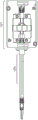
Fig. 2 illustrates a typical surgical instrument 200 for performing robotic laparoscopic surgery. The surgical instrument comprises a base 201, by means of which base 201 the surgical instrument is connected to the robot arm. A shaft 202 extends between the base 201 and the hinge 203. The hinge 203 terminates in an end effector 204. In fig. 2, a pair of serrated jaws is illustrated as end effector 204. The hinge 203 allows the end effector 204 to move relative to the shaft 202. It is desirable to provide at least two degrees of freedom to the motion of end effector 204 via a hinge.
Fig. 3 illustrates an example of a known surgical instrument 300 in which the end effector 204 is permitted to move relative to the shaft 202 via a pitch joint 301 and two yaw joints 302. The joint 301 enables the end effector 204 to rotate about a pitch axis 303. Joint 302 enables each jaw of end effector 204 to rotate about yaw axis 304. The joints are driven by cables 306, 307 and 308. The pulley 305 is used to guide the cables 307 and 308 from their channels across the pitch joint to the yaw joint. The pulley 305 is offset from the central axis of the hinge 203. The outer diameter of the shaft is 8mm in order to accommodate the number, size and location of the internal elements of the articulated part.
It is desirable to reduce the outer diameter of the instrument in order to minimize the size of the incision through the patient's skin and to minimize disruptions in the patient's body. It is also desirable to minimize the weight of the surgical instrument to minimize the size and weight of the robot base and arms required to support the instrument, thereby making the robot as a whole more compact and therefore occupying less space in the operating room and being able to move more within the operating room.
In a typical laparoscopic procedure, the surgeon utilizes many instruments and thus changes one instrument to another multiple times. It is therefore desirable to minimize the time taken and to maximize the convenience of detaching one instrument from the robotic arm and attaching a different instrument. In addition, it is desirable to minimize the time it takes to set up an instrument ready for use once it has been attached to the robotic arm.
Disclosure of Invention
According to an aspect of the present invention, there is provided a robotic surgical instrument comprising: a shaft; an end effector comprising a first end effector element and a second end effector element; a hinge connecting the end effector to the shaft, the hinge comprising: a first joint drivable by a first pair of drive elements, the first joint allowing rotation of the end effector about a first axis transverse to a longitudinal axis of the shaft; a second joint drivable by a second pair of drive elements, the second joint permitting rotation of the first end effector element about a second axis transverse to the first axis; and a third joint drivable by a third pair of drive elements, the third joint permitting rotation of the second end effector element about the second axis; the robotic surgical instrument further includes a pulley arrangement about which the second and third pairs of drive elements are constrained to move, the second and third pairs of drive elements having symmetrically opposed paths about the pulley arrangement, the pulley arrangement including: a first set of pulleys rotatable about the first axis; and a second set of pulleys configured to redirect the second and third pairs of drive elements from the first set of pulleys into the shaft, the second set of pulleys including a first pulley and a second pulley, the first and second pulleys being located on opposite sides of the first joint in a longitudinal direction of the shaft, wherein each pulley of the second set of pulleys is rotatable about an axis parallel to and offset from the first axis.
Drawings
The invention will now be described by way of example with reference to the accompanying drawings. In the figure:
FIG. 1 illustrates a surgical robot performing a surgical procedure;
FIG. 2 illustrates a known surgical instrument;
FIG. 3 illustrates a known arrangement of an articulated end effector of a surgical instrument;
fig. 4 illustrates a surgical robot;
fig. 5a and 5b illustrate the distal end of the surgical instrument;
fig. 6a and 6b illustrate the pulley arrangement of the distal end of the surgical instrument of fig. 5a and 5b in a straight configuration;
FIG. 7 illustrates the pulley arrangement of the distal end of the surgical instrument of FIGS. 5a and 5b in various non-straight configurations;
FIG. 8 illustrates an offset pulley of the pulley arrangement shown in FIGS. 5a and 5 b;
FIG. 9 illustrates a non-straight configuration of the distal end of the surgical instrument;
fig. 10 illustrates the support and reorienting pulley of the articulating portion of the surgical instrument;
FIG. 11 illustrates different views of the support body and the redirection pulley of FIG. 10;
figures 12 and 13 illustrate the support body of the hinge of figures 10 and 11 separately;
FIG. 14 illustrates a spindle-mounted redirection pulley mounted to the support body of FIGS. 12 and 13;
FIG. 15 illustrates the ramps and grooves of the support body of FIGS. 12 and 13;
figures 16a and 16b illustrate the arrangement of the drive element in the instrument shaft;
fig. 17a and 17b illustrate two views of the surgical instrument;
FIG. 18 illustrates spokes in an instrument shaft;
19a, 19b and 19c illustrate three views of the instrument interface;
figures 20a and 20b illustrate a tensioning mechanism;
21a, 21b and 21c illustrate three views of the drive assembly interface of the robotic arm;
22a, 22b and 22c illustrate the configuration of the instrument interface element;
FIG. 23 illustrates a configuration of drive assembly interface elements;
FIG. 24 illustrates the instrument interface engaged in the drive assembly interface; and
fig. 25 illustrates another view of the instrument interface.
Detailed Description
Fig. 4 illustrates a surgical robot having an arm 400 extending from a base 401. The arm includes a plurality of rigid limbs 402. The limbs are articulated by revolute joints 403. The proximal-most limb 402a is coupled to the base by a joint 403 a. It is coupled in series with the other limb by a further joint 403. Suitably, wrist 404 is comprised of four separate revolute joints. The wrist 404 couples one limb 402b of the arm to the distal-most limb 402 c. The distal-most limb 402c carries an attachment 405 for a surgical instrument 406. Each joint 403 of the arm has: one or more motors 407 operable to cause rotational motion at the respective joints; and one or more position and/or torque sensors 408 that provide information about the current configuration and/or load at this joint. Suitably, the motor is arranged close to the joint whose movement is driven by the motor, in order to improve the weight distribution. For clarity, fig. 4 shows only some of the motors and sensors. The arm may be generally described in the applicant's co-pending patent application PCT/GB 2014/053523.
The arms terminate in attachments 405 to interface with instruments 406. Suitably, the instrument 406 takes the form described in relation to fig. 2. The diameter of the instrument is less than 8 mm. Suitably, the instrument has a diameter of 5 mm. The diameter of the instrument may be less than 5 mm. The instrument diameter may be the diameter of the shaft. The instrument diameter may be the diameter of the profile of the hinge. Suitably, the diameter of the profile of the hinge portion matches or is narrower than the diameter of the shaft. The attachment 405 includes a drive assembly for driving the articulation of the instrument. The movable interface elements of the drive assembly interface mechanically engage corresponding movable interface elements of the instrument interface to transfer drive from the robotic arm to the instrument. During a typical procedure, one instrument is changed over to another instrument multiple times. Thus, during surgery, the instrument can be attached to and detached from the robotic arm. Features of the drive assembly interface and the instrument interface facilitate their alignment when engaged with each other to reduce the accuracy required by a user to align them.
Controllers for the motor, torque sensor and encoder are assigned to the robot arm. The controller is connected to the control unit 409 via a communication bus. The control unit 409 comprises a processor 410 and a memory 411. The memory 411 stores software executable by the processor in a non-transitory manner to control the operation of the motor 407, causing the arm 400 to operate as described herein. In particular, software may control the processor 410 to cause the motor to be driven (e.g., via an assigned controller) based on input from the sensors 408 and the surgeon command interface 412. The control unit 409 is coupled to the motor 407 to drive the motor 407 according to an output generated by executing software. Control unit 409 is coupled to sensor 408 to receive sensed inputs from the sensor and to command interface 412 to receive inputs from the command interface. For example, the respective couplings may each be an electrical or optical cable, or may be provided by a wireless connection. The command interface 412 includes one or more input devices whereby a user may request movement of the end effector in a desired manner. For example, the input device may be a manually operable mechanical input device (such as a control handle or joystick), or a non-contact input device (such as an optical gesture sensor). Software stored in memory 411 is configured to respond to these inputs and cause the shutdown of the arm and the instrument to move accordingly according to a predetermined control strategy. The control strategy may include a safety feature that regulates movement of the arm and instrument in response to command inputs. Thus, in summary, the surgeon at command interface 412 may control instrument 406 to move in a manner to perform a desired surgical procedure. The control unit 409 and/or command interface 412 may be remote from the arm 400.
Fig. 5a and 5b illustrate opposite views of the distal end of the surgical instrument. In fig. 5a and 5b, end effector 501 includes a pair of end effector elements 502, 503, the pair of end effector elements 502, 503 being depicted in fig. 5a and 5b as a pair of opposed serrated jaws. It should be understood that this is for illustrative purposes only. The end effector may take any suitable form, such as the form described above. The end effector 501 is connected to the shaft 504 by a hinge 505. The articulation 505 comprises a joint that allows the end effector 501 to move relative to the shaft 504. The first joint 506 allows the end effector 501 to rotate about a first axis 510. The first axis 510 is transverse to the longitudinal axis of the shaft 511. Second joint 507 allows first end effector component 502 to rotate about second axis 512. The second axis 512 is transverse to the first axis 510. Third joint 513 allows second end effector component 503 to rotate about second axis 512. Suitably, the first end effector member 502 and the second end effector member 503 are independently rotatable about the second axis 512 via the second joint and the third joint. The end effector element may be rotated in the same direction or in different directions by the second joint and the third joint. The first end effector member 502 may rotate about the second axis while the second end effector member 503 does not rotate about the second axis. The second end effector member 503 may rotate about the second axis while the first end effector member 502 does not rotate about the second axis.
Fig. 5a and 5b depict a straight configuration of a surgical instrument aligning an end effector with a shaft. In this orientation, the longitudinal axis of shaft 511 coincides with the longitudinal axis of the hinge and the longitudinal axis of the end effector. The articulations of the first, second, and third joints enable the end effector to assume a range of positions relative to the shaft. Fig. 9 illustrates some configurations of the distal end of the instrument in which the articulations around all of the first, second and third joints have been driven relative to the straight configuration of fig. 5a and 5 b.
Returning to fig. 5a and 5b, the distal end of the shaft terminates in a first joint 506. Hinge 505 includes a support 509. At one end, a support 509 is connected to the shaft 504 by a first joint 506. At the other end, a support 509 is connected to the end effector 501 by a second joint 507 and a third joint 513. Thus, the first joint 506 allows the support 509 to rotate about the first axis 510 relative to the shaft 504; and second joint 507 and third joint 513 allow end effector elements 502, 503 to rotate about second axis 512 relative to support 509.
In the figure, both the second joint 507 and the third joint 513 are allowed to rotate about the same axis 512. However, the second joint and the third joint may alternatively allow the end effector element to rotate about different axes. The axis of rotation of one of the end effector elements may be offset from the axis of rotation of the other end effector element in the longitudinal direction of shaft 504. The axis of rotation of one of the end effector elements may be offset from the axis of rotation of the other end effector element in a direction transverse to the longitudinal direction of shaft 504. The axis of rotation of one of the end effector elements may be non-parallel to the axis of rotation of the other end effector element. The axes of rotation of the end effector elements 502, 503 may be offset and/or angled with respect to each other in the longitudinal direction of the shaft and/or in a direction perpendicular to the longitudinal direction of the shaft. This may be desirable because the end effector element is asymmetric. For example, in an electrosurgical element, a first end effector element may be powered and a second end effector element is unpowered and isolated from the first end effector element. For this purpose, the axes of rotation of the two end effector elements may be offset in a direction perpendicular to the longitudinal direction of the shaft. In another example, the first end effector element may be a blade and the second end effector element a planar cutting surface. To facilitate use of the blade, the axes of rotation of the two end effector elements may be at an angle to each other.
The articulation of the articulation is driven by a drive element. The drive member is an elongate member extending from a joint in the articulation section through the shaft to the instrument interface. Suitably, each drive element may be laterally flexible over its major length at least in those regions that engage the articulation and the inner component of the instrument interface. In other words, each drive element may flex in a given area transverse to its longitudinal axis. This flexibility enables the drive element to be wound around internal structures of the instrument, such as joints and pulleys. The drive element is flexible in its entirety transversely to its longitudinal axis. The drive element may be inflexible along its major length. The drive element resists compressive and tensile forces applied along its length. In other words, the drive element resists compressive and tensile forces acting in the direction of its longitudinal axis. The driving element has a high modulus. The drive element remains taut during operation. The drive element is not allowed to become loose. Thus, the drive element is able to transmit drive from the instrument interface to the joint. The drive element may be a cable.
Suitably, each joint is driven by a pair of drive elements. Referring to fig. 5a and 5b, the first joint 506 is driven by a first pair of drive elements a1, a 2. The second joint 507 is driven by a second pair of drive elements B1, B2. The third joint is driven by a third pair of drive elements C1, C2. Suitably, each joint is driven by its own pair of drive elements. In other words, each joint is driven by a dedicated pair of drive elements. Suitably, the joints are independently driven. As shown in the third pair of drive elements in fig. 5a and 5b, the pair of drive elements may be constructed as a single component. In this case, the single component is fixed to the joint at one point. For example, the third pair of drive elements C1, C2 includes a ball feature 520 secured to the third joint 513. This ensures that when a pair of drive elements is driven, the drive is transmitted to the movement of the joint about its axis. Alternatively, the pair of drive elements may be configured as two components. In this case, each individual component is fixed to the joint.
The surgical instrument of fig. 5a and 5b further comprises a pulley arrangement about which the second and third pairs of drive elements are constrained to move. Fig. 6a and 6b better illustrate the pulley arrangement. The support 509 is not shown in fig. 6a and 6b in order to more clearly illustrate the pulley arrangement. The pulley arrangement comprises a first set of pulleys 601. The first set of pulleys 601 is rotatable about the first axis 510. Thus, the first set of pulleys 601 rotates about the same axis as the first joint 506. The pulley arrangement further comprises a second set of pulleys 602. The pulley arrangement further comprises a pair of redirecting pulleys 603.
Figure 7 illustrates the pulley arrangement more clearly. The support body, the first articulation and the first pair of drive elements have all been omitted from fig. 7 in order to more clearly illustrate the pulley arrangement. The second set of pulleys includes a first pulley 701 and a second pulley 702. The first pulley 701 is rotatable about a third axis 703 parallel to the first axis 510. The third axis 703 is offset from the first axis 510 in both the longitudinal direction of the shaft and also in a direction transverse to the longitudinal direction of the shaft. The second pulley 702 is rotatable about a fourth axis 704 parallel to the first axis 510. The fourth axis 704 is offset from the first axis 510 in both the longitudinal direction of the shaft and also in a direction transverse to the longitudinal direction of the shaft. The third axis and the fourth axis are parallel but offset from each other. The third axis 703 and the fourth axis 704 lie in the same plane perpendicular to the longitudinal direction of the shaft. Fig. 8 illustrates the distal end of the surgical instrument from a different view, more clearly showing the off-axis of the first pulley 701 and the second pulley 702 of the second set of pulleys. By offsetting the first pulley 701 and the second pulley 702, the drive element wound around each pulley can extend along the shaft after being wound around the pulley. As shown in fig. 6a, the first pulley 701 and the second pulley 702 of the second set of pulleys 602 are located on opposite sides of the first joint 506 in the longitudinal direction of the shaft 504. The first pulley 701 and the second pulley 702 are located on opposite sides of the first pair of drive elements a1, a 2.
The second set of pulleys is located between the first set of pulleys and the machine interface end of the shaft. Suitably, the second set of pulleys is located within the shaft as shown in the figures. Alternatively, the second set of pulleys may be located within the articulation between the first knuckle 506 and the second knuckle 507. However, by positioning the second set of pulleys at the distal end of the shaft 508, the distance between the first and second joints is reduced, thereby reducing the stiffness of the support 509 required to maintain accurate positioning of the end effector 501, as compared to alternative arrangements in which the second set of pulleys are positioned in the articulation.
The first set of pulleys 601 includes a first pulley 705 and a second pulley 706. Both the first pulley 705 and the second pulley 706 rotate about the first axis 510. A first pulley 705 and a second pulley 706 of the first set of pulleys are located on opposite sides of the first joint 506 in the longitudinal direction of the shaft 504. A first pulley 705 and a second pulley 706 are located on opposite ends of the first axis 510. The first and second pulleys 705, 706 are located on opposite sides of the first pair of drive elements a1, a 2.
The second pair of drive elements B1, B2 are constrained to move around opposite sides of the first 705 and second 706 pulleys of the first set of pulleys 601. The second pair of drive elements B1, B2 are constrained to move around opposite sides of the first 701 and second 702 pulleys of the second set of pulleys 601. The second pair of drive elements is constrained to move around opposite sides of the first pulley 705 of the first set of pulleys 601 and the first pulley 701 of the second set of pulleys 602. The second pair of drive elements is constrained to move around opposite sides of the second pulley 706 of the first set of pulleys 601 and the second pulley 702 of the second set of pulleys 602.
The third pair of drive elements C1, C2 are constrained to move around opposite sides of the first 705 and second 706 pulleys of the first set of pulleys 601. The third pair of drive elements C1, C2 are constrained to move around opposite sides of the first pulley 701 and the second pulley 702 of the second set of pulleys 601. The third pair of drive elements is constrained to move around opposite sides of the first pulley 705 of the first set of pulleys 601 and the first pulley 701 of the second set of pulleys 602. The third pair of drive elements is constrained to move around opposite sides of the second pulley 706 of the first set of pulleys 601 and the second pulley 702 of the second set of pulleys 602.
The second and third pairs of drive elements are each constrained to extend beyond the first joint 506 to reach the second and third joints, respectively. Thus, the first of the second pair of drive elements B1 passes on the first joint axis 510 one side of the first pulley 705 of the first set of pulleys and the second of the second pair of drive elements B2 passes on the first joint axis 510 the opposite side of the second pulley 706 of the first set of pulleys so that the length of the second pair of drive elements B1, B2 remains the same regardless of how the support 509 rotates about the first joint 506. Similarly, a first one of the third pair of drive elements C1 passes on the first joint axis 510 one side of the second pulley 706 of the first set of pulleys and a second one of the third pair of drive elements C2 passes on the first joint axis 510 the opposite side of the first pulley 705 of the first set of pulleys such that the length of the third pair of drive elements C1, C2 remains the same regardless of how the support 509 rotates about the first joint 506. If the arrangement of the instrument interface is symmetrical for both the second pair of drive elements B1, B2 and the third pair of drive elements C1, C2, the length of the second pair of drive elements is the same as the length of the third pair of drive elements for all rotational angles of the support 509 about the first joint 506. In each configuration of the surgical instrument, the second and third pairs of drive elements are held taut. They are never loose. Thus, there is no bounce when articulating any joint of the surgical instrument. Thus, in each configuration of the surgical instrument, full control of all three degrees of freedom of movement of the surgical instrument is achieved.
Suitably, each pulley of the first set of pulleys 601 comprises a pair of pulley elements. First pulley 705 includes an inner pulley member 708 and an outer pulley member 709. The inboard pulley element 708 is located between the outboard pulley element 709 and the first pair of drive elements a1, a 2. Suitably, the inboard pulley element 708 abuts the outboard pulley element 709. Inner pulley member 708 may be secured using outer pulley member 709. Inner pulley element 708 may be integrally formed with outer pulley element 709. The second pulley 706 includes an inner pulley member 710 and an outer pulley member 711. The inner pulley member 710 is located between the outer pulley member 711 and the first pair of drive members a1, a 2. Suitably, the inner pulley member 710 abuts the outer pulley member 711. The inner pulley member 710 may be secured with the outer pulley member 711. The inner pulley member 710 may be integrally formed with the outer pulley member 711. Each pulley element includes a groove for seating a drive element.
Suitably, each pulley of the second set of pulleys 602 comprises a pair of pulley elements. The first pulley 701 includes an inner pulley member 712 and an outer pulley member 713. The inboard pulley element 712 is located between the outboard pulley element 713 and the first pair of drive elements a1, a 2. Suitably, the inner pulley element 712 abuts the outer pulley element 713. The inner pulley element 712 may be secured with the outer pulley element 713. The inner pulley element 712 may be integrally formed with the outer pulley element 713. The second pulley 702 includes an inner pulley member 714 and an outer pulley member 715. The inner pulley member 714 is located between the outer pulley member 715 and the first pair of drive elements a1, a 2. Suitably, the inner pulley member 714 abuts the outer pulley member 715. The inner pulley member 714 may be secured with an outer pulley member 715. The inner pulley member 714 may be integrally formed with the outer pulley member 715. Each pulley element includes a groove for seating a drive element.
The second pair of drive elements B1, B2 are constrained to move about the inner pulley element 712 of the first pulley of the second set of pulleys and the outer pulley element 715 of the second pulley of the second set of pulleys. The second pair of drive elements B1, B2 are constrained to move about the inner pulley element 708 of the first pulley of the first set of pulleys and the outer pulley element 711 of the second pulley of the first set of pulleys.
The third pair of drive elements C1, C2 are constrained to move about the outer pulley element 713 of the first pulley of the second set of pulleys and the inner pulley element 714 of the second pulley of the second set of pulleys. The third pair of drive elements C1, C2 are constrained to move about the outer pulley element 709 of the first pulley of the first set of pulleys and the inner pulley element 710 of the second pulley of the first set of pulleys.
Thus, the second pair of drive elements B1, B2 has a symmetrically opposed path around the first set of pulleys 601 and the second set of pulleys 602, rather than the third pair of drive elements C1, C2. In the straight configuration of the end effector shaft-aligned instrument, the path of the second pair of drive elements B1, B2 about the pulley arrangement is rotationally symmetric about the longitudinal axis of shaft 511 with the path of the third pair of drive elements C1, C2 about the pulley arrangement. The second pair of drive elements B1, B2 and the third pair of drive elements C1, C2 emerge from the second set of pulleys 602 in a symmetrical arrangement into the distal end of the shaft. As can be seen more readily from fig. 7, drive elements B1 and C2 appear adjacent to each other on one side of the shaft, while drive elements C1 and B2 appear adjacent to each other on the opposite side of the shaft. The arrangement of the drive elements B1 and C2 in the shaft is rotationally symmetric about the longitudinal axis of the shaft 511 with respect to the arrangement of the drive elements C1 and B2 in the shaft. The second set of pulleys 602 redirects the second and third pairs of drive elements from the first set of pulleys 601 into the shaft in this manner.
Fig. 7 illustrates the distal end of the surgical instrument in five different configurations. Configuration (c) is the straight configuration previously mentioned, wherein the end effector is aligned with the instrument shaft. In configurations (a), (b), (d), and (e), rotation about the first joint occurs relative to configuration (c). In configurations (a), (b), (d), and (e), no rotation about either the second joint or the third joint occurs relative to configuration (c). Starting from configuration (c), drive element a2 (not shown) is pulled to cause rotation about first axis 510, resulting in the arrangement of configuration (b). Further pulling of drive element a2 causes further rotation about first axis 510, resulting in the arrangement of configuration (a). Starting from configuration (c), drive element a1 (not shown) is pulled so as to cause rotation about first axis 510 in a direction opposite to configurations (a) and (b), thereby causing the arrangement of configuration (d). Further pulling of drive element a1 causes further rotation about first axis 510, resulting in the arrangement of configuration (e).
The rotation of the end effector 501 about the first axis 510 is defined by the maximum travel of the first pair of drive elements a1, a2 about the first joint 506. Configuration (a) shows the end effector 501 at maximum rotation in one direction about the first axis 510, and configuration (e) shows the end effector 501 at maximum rotation in the opposite direction about the first axis 510. Relative in the two configurationsThe maximum angle of rotation at the longitudinal axis of the shaft 511 is the angle The second set of
 pulleys 602 is positioned relative to the first set of pulleys 601 so as to be at a maximum rotation angle even though It is also ensured that the second and third pairs of drive elements remain in contact with both the first and second sets of
 pulleys 601, 602. For all angles of rotation of the end effector 501 about the first axis 510, the end effector 501 is always located within the cone defined by the tangent connecting the first pulley 701 of the second set of pulleys and the first pulley 705 of the first set of pulleys. This tangent is the path taken by the drive element. When the second and third joints are held in the straight configuration of fig. 5a and 5b, the end effector 501 is located in the cone, as shown in all configurations of fig. 7. As can be seen from fig. 7, without the second set of pulleys 602, the drive elements B2 and C1 would lose contact with the first set of pulleys 601 in configuration (a). Without the second set of pulleys 602, the drive elements B1 and C2 would lose contact with the first set of pulleys 601 in configuration (e).
The second and third pairs of drive elements remain in contact with the first and second sets of pulleys for all angles of rotation of the end effector relative to the longitudinal axis of the shaft. Thus, the length of the second pair of drive elements B1, B2 will remain the same regardless of rotation about the first joint 506. Additionally, the length of the third pair of drive elements C1, C2 will remain the same regardless of rotation about the first joint 506. Thus, regardless of how first joint 506 is driven about first axis 510, the second set of pulleys enables tension to be maintained in the second drive element and the third drive element. Thus, control of the second and third drive elements is maintained regardless of how the first joint 506 is driven about the first axis 510.
The pulley arrangement further comprises a pair of redirecting pulleys 716, 717. These redirection pulleys are located in the articulation 505 between the first knuckle 506 and the second and third knuckles 507 and 513. The redirection pulleys are positioned to redirect the second pair of drive elements B1, B2 from the first set of pulleys 601 to the second joint 507 and to redirect the third pair of drive elements C1, C2 from the first set of pulleys 601 to the third joint 513.
The second pair of drive elements B1, B2 is constrained to move about the first redirection pulley 716. The first redirect pulley 716 rotates about a first redirect pulley axis 718. The first redirection pulley axis 718 is at an angle θ to the first axis 510. The angle θ redirects the first drive element of the second pair B1 from the exit point of the first pulley 705 of the first set of pulleys 601 to the pick point 721 on the second joint 507. Suitably, the first redirecting pulley 716 comprises a groove for seating the drive element B1. The third pair of drive elements C1, C2 are not constrained to move about the first redirect pulley 716. However, the second of the third pair of drive elements C2 is passed between the exit point of the third joint 513 and the pick-up point on the first pulley 705 of the first set of pulleys 601 by the first redirect pulley 716. The drive element C2 may be partially surrounded by the first redirect pulley 716. For example, the drive element C2 may pass partially between the two wings of the groove of the first redirection pulley 716, but the drive element C2 is not disposed in the groove of the first redirection pulley 716.
The third pair of drive elements C1, C2 is constrained to move about the second redirecting pulley 717. Second redirecting pulley 717 rotates about second redirecting pulley axis 719. The second redirecting pulley axis 719 is at an angle ψ from the first axis 510. The angle ψ causes the first of the third pair of drive elements C1 to be redirected from the exit point 720 of the second pulley 706 of the first set of pulleys 601 to the pick-up point on the third joint 513. Suitably, the second redirecting pulley 717 comprises a groove for seating the drive element C1. The second pair of drive elements B1, B2 are not constrained to move about the second redirecting pulley 717. However, the second drive element of the second pair B2 is passed between the exit point 720 of the second joint 507 and the pick-up point on the second pulley 706 of the first set of pulleys 601 by the second re-direction pulley 717. The driving element B2 may be partially surrounded by the second redirecting pulley 717. For example, the drive element B2 may pass partially between two wings of the groove of the second redirecting pulley 717, but the drive element B2 is not disposed in the groove of the second redirecting pulley 717.
The take-off point is the point at which the drive element loses contact with the pulley. The pick-up point is the point at which the drive element first contacts the pulley. For a drive element passing directly from the first pulley to the second pulley, the exit point of the drive element from the first pulley and the pick-up point of the drive element on the second pulley are points on the tangent to both the first and second pulleys, the exit point being where the tangent intersects the first pulley and the pick-up point being where the tangent intersects the second pulley. This is for illustrative purposes only and is negligible depending on the thickness of the drive element. Thus, in practice, the thickness of the tangent line is equal to the thickness of the drive element, the take-off point is where one side of the tangent line meets the first pulley, and the pick-up point is where the other side of the tangent line meets the second pulley.
The redirect pulley 716 causes the drive element B1 to wrap more completely around the second knuckle 507 than would occur if the redirect pulley 716 were not there, thereby increasing the engagement length between the drive element B1 and the second knuckle 507. Accordingly, the drive element B1 has greater travel about the second joint 507 and, thus, can cause the end effector element 502 to rotate about the second axis 512 more than without the redirection pulley 716. The redirect pulley 716 causes the pick point of the drive element B1 on the second joint 507 to change relative to the case without the redirect pulley 716.
The redirect pulley 717 causes the drive element C1 to wrap more completely around the third joint 513 than would occur if the redirect pulley 717 were not there, thereby increasing the length of engagement between the drive element C1 and the third joint 513. Thus, drive element C1 has a greater travel about third joint 513, and thus can cause end effector element 503 to rotate about second axis 512 more than without redirection pulley 717. The redirect pulley 717 causes the pick-up point of the drive element C1 on the third joint 513 to change relative to the case without the redirect pulley 717.
The redirection pulleys are each positioned on opposite sides of the hinge towards an outside edge of the hinge. This is more easily seen in fig. 5 a. As seen in fig. 6a, each of the redirecting pulleys is located between the longitudinal axis of the hinge and the outer profile of the hinge, on opposite sides of the hinge. Suitably, the diameter of each redirecting pulley maximises the available space. In other words, the redirecting pulley is as large as possible while enabling one drive element to engage the pulley on one side of the pulley and the other drive element to approach the pulley unobstructed on the opposite side of the pulley, the pulley and the two drive elements being enclosed within the profile of the hinge.
The first redirection pulley 716 lies in a plane defined by three points: (i) the desired exit point of the first pulley 705 of the first set of pulleys 601 is the drive element B1; (ii) the desired pick point of drive element B1 on second joint 507; and (iii) a point on the boundary of the articulation that causes the first redirecting pulley 716 to be enclosed within the boundary of the articulation when located in the plane. Suitably, the first redirect pulley 716 is as large as possible while still lying in this plane, enclosed within the contour of the hinge, does not obstruct the path of the drive element C2, and enables the drive element B1 to move freely thereabout.
Second redirecting pulley 717 lies in a plane defined by three points: (i) a desired exit point of the second pulley 706 of the first set of pulleys 601 is the drive element C1; (ii) the desired pick point of drive element C1 on third joint 513; and (iii) a point on the boundary of the hinge that causes the second diverting pulley 717 to be enclosed within the boundary of the hinge when located in the plane. Suitably, the second diverting pulley 717 is as large as possible while still lying in this plane, enclosed within the contour of the hinge, does not obstruct the path of the drive element B2, and enables the drive element C1 to move freely thereabout.
A desired exit point and a desired pickup point are determined to allow a desired travel of the drive element about the second joint and the third joint to allow a desired maximum rotation of the end effector element about the second axis.
The first and second redirecting pulleys are located in different planes. As can be seen in fig. 6a, these planes may be symmetrical with respect to a plane perpendicular to the first axis 510. These planes may be rotationally symmetric about a plane perpendicular to the first axis 510. In particular, the planes may be rotationally symmetric about a line in a plane perpendicular to the first axis 510. These planes are rotationally symmetric about the longitudinal axis of the shaft 511 when the instrument is in the straight configuration illustrated in fig. 6 a. This is second order rotational symmetry. These planes may be a mapping of each other in a plane perpendicular to the first axis 510. In the illustrated example, end effector elements 502 and 503 are rotationally symmetric, and the path of the drive elements around joints 507 and 513 are rotationally symmetric. Alternatively, the axes of end effector elements 502 and 503 may be rotationally asymmetric and/or the path of the drive elements around joints 507 and 513 may be asymmetric. The path of the drive elements around joints 507 and 513 may be asymmetric due to the joints having different diameters (to achieve different tension ratios) and/or being positioned at different places off the centerline of support 509. In any of these alternative examples, the first and second redirecting pulleys 716, 717 will not be rotationally symmetric. The first and second redirecting pulleys 716, 717 will have different sizes and/or different positions in order to cause the drive element to have the desired exit point and the desired pick point as previously described.
Suitably, the entire pulley arrangement, including the first set of pulleys, the second set of pulleys, and the redirecting pulley, is symmetrical about a plane perpendicular to the first axis 510. In particular, with respect to a plane perpendicular to the first axis 510, the first partial arrangement comprising the first pulley of the first set of pulleys 705, the first pulley of the second set of pulleys 701, and the first redirection pulley 716 is rotationally symmetric with the second partial arrangement comprising the second pulley of the first set of pulleys 706, the second pulley of the second set of pulleys 702, and the second redirection pulley 717. Suitably, in the mentioned plane perpendicular to the first axis 510, the first partial arrangement is a mapping of the second partial arrangement. The second pair of drive elements B1, B2 is constrained to move about the pulley arrangement in a manner that is rotationally symmetrical opposite to the third pair of drive elements C1, C2 being constrained to move about the pulley arrangement. Because the pulley arrangement has the described symmetry, the second and third drive elements constrained to move symmetrically about the pulley arrangement also have the same symmetry. Thus, the path of the second pair of drive elements B1, B2 around the pulley arrangement is rotationally symmetric to the path of the third pair of drive elements C1, C2 around the pulley arrangement.
In an exemplary embodiment, the first and second redirecting pulleys are mounted on a support 509. Fig. 10 illustrates the support 509 and the redirecting pulley separately. Each of which is mounted to the surface of the support 509 by a spindle. The main shaft 1001 secures the first redirecting pulley 716 to the support 509. The main shaft 1102 also fixes the second redirecting pulley 717 to the support 509.
As shown more clearly in the view shown in fig. 11, the support 509 has a ramp 1101, and the first redirecting pulley 716 is mounted to the ramp 1101. The first redirection pulley 716 has a mounting surface 1104, the mounting surface 1104 facing the ramp 1101 of the support 509. The mounting surface 1104 is flush with the ramp 1101.
The first redirection pulley has an opposing surface 1105 opposite the mounting surface 1104. The opposing surface 1105 is parallel to the mounting surface 1104. The support 509 has another ramp to which a second redirecting pulley 717 is mounted by a main shaft 1103. The second redirecting pulley 717 has a mounting surface 1106, the mounting surface 1106 facing the inclined surface 1102 of the support 509. The mounting surface 1106 is flush with the ramp 1102. The second diverting pulley has an opposing surface 1107 opposing the mounting surface 1102. The opposing surface 1107 is parallel to the mounting surface 1102.
The slope of the support 509 is not parallel to the longitudinal axis of the support. The inclined plane 1101 of the support 509 lies in a plane 1108, the plane 1108 being parallel to the plane 1109 in which the first redirecting pulley 716 lies. In other words, the bevel 1101 lies in a plane 1108 parallel to a plane 1109, the plane 1109 being defined by the following three points: (i) the desired exit point of the first pulley 705 of the first set of pulleys 601 is the drive element B1; (ii) the desired pick point of drive element B1 on second joint 507; and (iii) points on the boundary of the hingeThis point causes the first redirecting pulley 716 to be enclosed within the boundaries of the hinge when located in plane 1109. Plane 1108 of ramp 1101 is at half the width (illustrated as d in fig. 11) of first redirecting pulley 7161) Deviating from the plane 1109 defined by these points.
The ramp 1102 of the support 509 lies in a plane 1110, the plane 1110 being parallel to the plane 1111 in which the second diverting pulley 717 lies. In other words, ramp 1102 lies in a plane 1110 that is parallel to plane 1111, which plane 1111 is defined by three points: (i) a desired exit point of the second pulley 706 of the first set of pulleys 601 is the drive element C1; (ii) the desired pick point of drive element C1 on third joint 513; and (iii) a point on the boundary of the hinge that causes the second diverting pulley 717 to be enclosed within the boundary of the hinge when located in plane 1111. Plane 1110 of ramp 1101 is half the width of second redirecting pulley 717 (illustrated as d in FIG. 11)2) Deviating from the plane 1111 defined by these points. Suitably, the first and second redirecting pulleys 716, 717 have the same shape and size. In this case, d1=d2。
As previously discussed, each redirection pulley is mounted to a corresponding ramp of the support body by a main shaft. The spindle includes a spindle body and a spindle head. The spindle body passes through a central orifice of the redirection pulley. The central aperture is a through-hole extending vertically between the mounting surface and the opposing surface of the redirection pulley. The spindle body passes through the central orifice of the redirection pulley and into the hole of the support body. Fig. 12 and 13 illustrate the support 509 in isolation. Exemplary embodiments of the holes of the support are depicted in these figures. The holes are recesses in the support body that taper to a certain point. The spindle body passes through the initial opening of the bore and is securely stored into the tapered section. The spindle head is larger than the center opening of the heavy directional pulley and therefore cannot pass through the center opening of the redirecting pulley. The spindle head thus secures the redirecting pulley flush against the inclined surface of the support body. The spindle head contacts at least a portion of the opposing surface of the redirection pulley, by which contact the redirection pulley is held against the ramp.
Referring to fig. 14, the diameter of the hole 1401 through the support is larger than the diameter of the spindle body 1403. The diameter of the central aperture 1402 of the redirection pulley may be larger than the diameter of the main shaft body 1403. Thus, the spindle body may fit loosely through the central aperture of the redirection pulley. In the example above the tapered section, the spindle body fits loosely through the hole of the support body (except in the area where it is fixed to the hole). Typically, the holes through the support are created during manufacture by drilling holes through the inclined surface of the support. Since the opening of the hole in the bevel is larger in diameter than the spindle body, the accuracy of the angle at which the support body is drilled to create the hole is not important. The spindle is positioned in the hole at the correct angle to bring the redirecting pulley flush with the bevel. It is important that the angle of the hole is drilled very accurately if the fit of the spindle body through the hole is a tight fit and as a means of causing the redirection pulley to rotate about the redirection pulley axis 718, 719. In this case the pulley would be tightly mounted to the main shaft, which would fit tightly into the hole and prevent the pulley from traveling. Thus, there will be no margin for manufacturing variations in the angles of the bores drilled through the support body. However, in the depicted embodiment, the redirection pulley is caused to rotate about redirection pulley axes 718, 719 due to the bevel perpendicular to redirection pulley axes 718, 719 that keeps the redirection pulley flush against support 509. Thus, in the described implementation, greater manufacturing accuracy variations in the angles at which holes are drilled through the support are acceptable.
The bevels 1101 and 1102 of the support are not parallel to each other. The bevel may be symmetrical about a plane perpendicular to the first axis 510. The bevel may be rotationally symmetric about a plane perpendicular to the first axis 510. In particular, the bevel may be rotationally symmetric about a line in a plane perpendicular to the first axis 510. When the instrument is in the straight configuration illustrated in fig. 5a, the bevel is rotationally symmetric about the longitudinal axis of the shaft 511. This is second order rotational symmetry. The bevels may be a mapping of each other in a plane perpendicular to the first axis 510.
Referring to fig. 15, in one example, the support 509 includes a recess adjacent each ramp for seating a drive element. The support body includes a recess 1501 adjacent the ramp 1101 for seating a second drive element C2 of the third pair of drive elements. The drive element C2 is seated in the groove 1501 and is partially surrounded by the first redirection pulley 716. The support body includes a recess 1502 adjacent the ramp 1102 for seating a second drive element B2 of the second pair of drive elements. Fig. 11 shows a groove 1502. The driving member B2 is seated in the groove 1502 and is partially surrounded by the second redirecting pulley 717.
The first, second, and third pairs of drive elements extend through the instrument shaft from a distal end of the shaft connected to the articulating portion to a proximal end of the shaft connected to a drive mechanism of the instrument interface. Fig. 17a and 17b illustrate two views of a first, second and third pair of drive elements extending from the depicted hinge to an exemplary mechanical interface 1701. In an exemplary embodiment, the second and third pairs of drive elements overlap in the shaft, emerging from the proximal end of the shaft in a different arrangement than if they were in the distal end of the shaft. Fig. 16a and 16b illustrate cross-sections of the shaft depicting the position of the drive element.
Figure 16a shows a cross-section of the shaft at the distal end of the shaft. In other words, fig. 16a shows the position of the drive element just off the second set of pulleys 602. The drive elements a1 and a2 are located at opposite sides of the shaft after exiting the first joint 506. On the side of the shaft opposite the drive elements B1 and C2 (adjacent to each other), the drive elements C1 and B2 are also adjacent to each other. Drive elements C1 and B2 are offset from drive elements B1 and C2 about an axis 1601 transverse to axis 1602 connecting drive elements a1 and a 2. This is a result of the off-axis of the two pulleys of the second set of pulleys.
Fig. 16b shows a cross-section of the shaft at the proximal end of the shaft. In other words, fig. 16b shows the position of the drive element just prior to exiting the shaft into the instrument interface. The first pair of drive elements a1 and a2 are located on opposite sides of the shaft in a similar arrangement to that in fig. 16 a. The first pair of drive elements may be brought closer together by virtue of the first pair of drive elements having been moved slightly towards each other over their extent through the shaft. In fig. 16B, the drive element B1 is located on the opposite side of the shaft from the position in fig. 16 a. In fig. 16b, the drive element C1 is located on the opposite side of the shaft from the position in fig. 16 a. To this end, drive element B1 and drive element C1 extend along the shaft non-parallel to the longitudinal axis of shaft 511. In contrast, drive element B1 and drive element C1 overlap each other over the shaft. This overlap occurs in the case of no collision of the drive elements B1 and C1, because they are offset in fig. 16a in view of the fact that the pulleys of the second set of pulleys 602 have offset axes. Drive element B2 moved slightly in the shaft, but remained on the same side of the shaft as in fig. 16a to appear at the proximal end of the shaft adjacent drive element B1. Drive element C2 moves slightly in the shaft, but remains on the same side of the shaft as in fig. 16a to appear at the proximal end of the shaft adjacent drive element C1.
The instrument interface comprises a further pulley arrangement about which the first, second and third pairs of drive elements are constrained to move. Drive elements a1, a2, B1, B2, C1, and C2 are present at the proximal end of the shaft in a configuration that enables them to directly engage with components of the instrument interface. In one embodiment, a drive element is present at the proximal end of the shaft (as shown in fig. 16 b) for direct engagement with another pulley arrangement of the instrument interface described herein. Suitably, the first, second and third drive elements extend from the pulley arrangement at the distal end of the shaft to the instrument interface without wrapping around any intervening pulleys. Suitably, there are no intervening pulleys in the shaft that constrain the first, second and/or third pairs of drive elements to move thereabout.
As can be seen in fig. 17a and 17b, the instrument interface is relatively flat. The instrument interface extends mostly in the central plane as viewed in fig. 17 a. Suitably, the instrument shaft 504 is rigidly attached to the instrument interface 1701. The instrument shaft 504 does not rotate or otherwise move relative to the instrument interface 1701. Suitably, the second axis 512 about which the end effector members 502, 503 rotate is perpendicular to the central plane of the instrument interface. This is the case in the straight configuration of the instrument shown in fig. 17a and 17 b. Thus, in the straight configuration of the instrument, the jaws of the end effector are movable in a central plane of the instrument interface.
The drive element may be a uniform component having the same shape and size along its length and be composed of the same material along its length. Alternatively, the drive element may be constituted by different parts. In one example, the portion of the drive element that engages with the components of the instrument interface (such as the pulley and the interface element) is flexible. Similarly, the portion of the drive element that engages components of the distal end of the surgical instrument, such as pulleys and joints in the articulation section, is flexible. Between these two flexible portions is spoke 1702 illustrated in fig. 17a and 17 b. Thus, each pair of drive elements comprises two spokes and two flexible portions. Each pair of drive elements forms a loop. The loop includes alternating spokes and flexible portions. The two spokes are enclosed primarily or entirely within the instrument shaft. One end of the distal flexible portion terminates in the distal end of one spoke and the other end terminates in the distal end of the other spoke. The distal flexible portion engages a component of the hinge. One end of the proximal flexible portion terminates in the proximal end of one spoke and the other end terminates in the proximal end of the other spoke. The proximal flexible portion engages a component of the instrument interface. The spokes are stiffer than the flexible portion. Suitably, the spokes are rigid. The spokes may be hollow. Typically, the diameter of the spokes is larger than the diameter of the flexible portion. Thus, the flexible portion may be a cable and the spokes are hollow tubes. The flexible portion may terminate where it meets the spokes. Alternatively, the spokes may encapsulate the material of the flexible portion. For example, the spokes may be a rigid sheath covering the flexible cable.
The spokes are stiffer than the flexible portion. Thus, by forming a pair of drive elements from spokes and flexible portions, the likelihood of the drive elements stretching is reduced. For this reason, it is preferable to maximize the proportion of spokes in each drive element, while ensuring that the spokes do not come into contact with the hinge or parts of the instrument interface, and also ensuring that adjacent drive elements do not collide. The spokes are stronger than the flexible portion and therefore more resilient to compressive and tensile forces applied in any direction than the flexible portion. Thus, by integrating spokes, the drive element is overall stiff and less likely to stretch. Thus, the life of the drive element is extended before re-tensioning or replacement is required.
In fig. 18, spokes of drive elements A1, A2, B1, and C1 are visible, labeled A1s, A2s, B1s, and C1s, respectively. Fig. 18 depicts a straight configuration of the surgical instrument with the end effector 501 aligned with the shaft 504. As can be seen in fig. 18, the distal flexible portion of drive element A1 terminates in spoke A1s at a point 1801 along the longitudinal direction x of the shaft. The longitudinal direction x is the direction of the longitudinal axis 511 of the shaft. The distal flexible portion of drive element A2 terminates in spoke A2s at point 1802 along the longitudinal direction x of the shaft. The distal flexible portion of the drive element B1 terminates in spoke B1s at a point 1803 along the longitudinal direction x of the shaft. The distal flexible portion of drive element C1 terminates in spoke C1s at point 1804 along the longitudinal direction x of the shaft. As can be seen in fig. 17a, the distal flexible portions of drive elements B2 and C2 terminate further in their respective spokes toward the proximal end of the shaft.
As can be seen in fig. 18, the longitudinal positions 1801, 1802, 1803 and 1804 at which the distal flexible portions of the drive elements terminate in the distal ends of the spokes are misaligned when the instrument is in the depicted straight configuration. Conversely, the longitudinal positions 1801, 1802, 1803, and 1804 are offset from one another. In other words, when the instrument is in the straight configuration, the distal ends of the spokes of the drive element are offset along the longitudinal direction of the shaft. In particular, in the straight configuration, the distal ends of adjacent spokes are offset along the longitudinal direction of the shaft. In a straight configuration, the distal ends of spokes that are not adjacent to each other may coincide along the longitudinal direction of the shaft. For example, in fig. 18, both non-adjacent spokes A1s and A2s terminate at the same point 1801, 1802 along the longitudinal direction of the shaft. Suitably, in each configuration of the surgical instrument, the distal ends of the spokes of the drive element are offset along the longitudinal direction of the shaft. In particular, suitably, in each configuration of the surgical instrument, the distal ends of adjacent spokes are offset along the longitudinal direction of the shaft.
As previously discussed with respect to fig. 16a and 16b, in embodiments where the drive elements pass directly from the pulley device at the distal end of the shaft to the pulley device in the instrument interface without moving around any intervening pulleys, the drive elements do not all extend parallel to each other in the shaft. A first one a1 of the first pair of drive elements extends substantially parallel to a second one a2 of the first pair of drive elements in the shaft. Drive elements a1 and a2 may move slightly closer to each other over the shaft length in a direction from the hinge to the instrument interface. The first drive element B1 of the second pair of drive elements extends at an angle in the shaft from the second drive element B2 of the second pair of drive elements. Drive element B1 also extends along an axis at an angle to drive elements a1, a2, C1, and C2. Drive element B2 extends along an axis at an angle to drive elements a1, a2, C1, and C2. A first one of the third pair of drive elements C1 extends at an angle in the shaft from a second one of the third pair of drive elements C2. Drive element C1 also extends along an axis at an angle to drive elements a1, a2, B1, and B2. Drive element C2 extends along an axis at an angle to drive elements a1, a2, B1, and B2.
The longitudinal position of the distal ends of the spokes is chosen so that the spokes do not collide when the instrument is articulated. Because the diameter of the spokes is larger than the diameter of the flexible portion, although the flexible portion may extend the length of the shaft without collision, the spokes cannot. Suitably, the longitudinal position of the distal ends of the spokes in the straight configuration of the instrument is such that no portion of any drive element contacts a portion of another drive element for any configuration of the end effector. Suitably, the location of the proximal and distal ends of the spokes in the straight configuration is selected to maximize the spoke length while meeting the condition that the drive element will not come into contact. The spokes are stiffer than the flexible portion. This therefore maximizes the stiffness of the drive element while enabling the drive element to be wrapped around the articulation and components in the instrument interface. This maximizes the strength of the drive element while enabling the drive element to be wrapped around the articulation and components in the instrument interface.
In fig. 19a, spokes of drive elements A1, A2, B1, and C1 are visible, labeled A1s, A2s, B1s, and C1s, respectively. Fig. 19a depicts a non-straight configuration of the surgical instrument, wherein the end effector 501 is not aligned with the shaft 504. As can be seen in fig. 19a, the proximal flexible portion of drive element A1 terminates in spoke A1s at a point 1901 along the longitudinal direction x of the shaft. The longitudinal direction x is the direction of the longitudinal axis 511 of the shaft. The proximal flexible portion of drive element A2 terminates in spoke A2s at point 1904 along the longitudinal direction x of the shaft. The proximal flexible portion of the drive element B1 terminates in spoke B1s at a point 1902 along the longitudinal direction x of the shaft. The proximal flexible portion of drive element C1 terminates in spoke C1s at point 1903 along the longitudinal direction x of the shaft. As can be seen in fig. 17a, the proximal flexible portions of drive elements B2 and C2 terminate further into their respective spokes toward the distal end of the shaft. The spokes may terminate in a proximal flexible portion inside the shaft, as in the example shown for drive elements B2 and C2. The spokes may terminate in a proximal flexible portion inside the instrument interface, as in the example shown for drive elements a1, a2, B1, and C1. Some of the spokes may terminate in the proximal flexible portion inboard of the shaft, and some of the spokes may terminate in the proximal flexible portion inboard of the instrument interface. In the design of the instrument interface depicted in fig. 19a, the drive elements B2 and C2 engage the pulley as they enter the instrument interface from the shaft, so the spokes of the drive elements B2 and C2 terminate in the shaft (not shown) in their proximal flexible portions to enable the proximal flexible portions to engage the pulley. The drive elements a1, a2, B1, and C1 all extend some distance into the instrument interface before engaging with components of the instrument interface, so the spokes of the drive elements a1, a2, B1, and C1 can extend into the instrument interface.
As can be seen in fig. 19a, the longitudinal positions 1901, 1902, 1903 and 1904 at which the proximal flexible portions of the drive elements terminate in the proximal ends of the spokes do not coincide. In contrast, longitudinal positions 1901, 1902, 1903, and 1904 are offset from one another. In other words, when the instrument is in the illustrated configuration, the proximal ends of the spokes of the drive element are offset along the longitudinal direction of the shaft. Suitably, for a straight configuration of the instrument, the proximal ends of the spokes of the drive element are offset along the longitudinal direction of the shaft. Specifically, in the straight configuration, the proximal ends of adjacent spokes are offset along the longitudinal direction of the shaft. In a straight configuration, the proximal ends of spokes that are not adjacent to each other may coincide along the longitudinal direction of the shaft. For example, in fig. 19a, both non-adjacent spokes B1s and C1s terminate at the same point 1902, 1903 along the longitudinal direction of the shaft. Suitably, in each configuration of the surgical instrument, the proximal ends of the spokes of the drive element are offset along the longitudinal direction of the shaft. In particular, suitably, in each configuration of the surgical instrument, the distal ends of adjacent spokes are offset along the longitudinal direction of the shaft.
The longitudinal position of the proximal ends of the spokes is chosen so that the spokes do not collide when the instrument is articulated. Suitably, the longitudinal position of the proximal ends of the spokes in the straight configuration of the instrument is such that no portion of any drive element contacts a portion of another drive element for any configuration of the end effector.
Each pair of drive elements engages a single instrument interface element in the instrument interface. Each drive element engages an instrument interface element in the instrument interface. In the example illustrated in fig. 19a, 19b and 19c, each drive element engages its own instrument interface element. A single instrument interface member drives a pair of drive members. Each drive element is independently driven by a single instrument interface. In alternative arrangements, there may be a compound drive motion in which more than one instrument interface element drives a single drive element, a single instrument interface element drives more than one pair of drive elements, or multiple instrument interface elements collectively drive multiple drive elements.
Fig. 19b illustrates the first instrument interface member 1905 engaging the first pair of drive members a1, a 2. The second instrument interface member 1906 engages a second pair of drive members B1, B2. The third instrument interface member 1907 engages a third pair of drive members C1, C2. Suitably, each drive element is secured to its associated instrument interface element. In other words, each drive element is secured with its associated instrument interface element.
The instrument interface 1701 has a significantly larger profile than the instrument shaft 504. Typically, the instrument shaft has a circular cross-section with a diameter of less than or equal to 5mm, and the corresponding cross-section through the instrument interface may be larger than the circular cross-section. The instrument interface includes an inner portion and an outer portion. The inner portion is bounded by dashed line 1950 (shown in fig. 19a and 19 b). The outer portion is the remainder of the instrument interface that is not in the inner portion. The inner portion is within the projected contour of the shaft. In other words, the inner portion is the portion of the instrument interface that would be enclosed if the shaft contour continued within the instrument interface. The outer portion is outside the projected contour of the shaft. In the illustrated example, the shaft has a constant circular cross-section, so the inner part is divided into cylinders having the same circular cross-section as the shaft and having the same longitudinal axis 511 as the shaft. In other words, the inner portion is an extrapolation of a constant cross section of the shaft in the instrument interface. The inner portion 1950 is shown from the side in fig. 19a and from the top in fig. 19 b.
The instrument interface member 1905 engages a first pair of drive members a1, a 2. As can be seen in fig. 19a, between the proximal end of the shaft and the instrument interface member 1905, a pair of drive elements a1, a2 are entirely within the inner portion 1950. Between the proximal end of the shaft and the instrument interface member 1905, a pair of drive elements a1, a2 are substantially parallel to the longitudinal axis of the shaft 511. Suitably, there are no intervening pulleys or other structures in the instrument interface that constrain the pair of drive elements a1, a2 to move thereabout between the proximal end of the shaft and the instrument interface element 1905. Suitably, only the instrument interface element 1905 engages its pair of drive elements a1, a2 in the inner portion 1950 of the instrument interface.
The instrument interface member 1906 engages the second pair of drive members B1, B2. The instrument interface element 1906 engages the second pair of drive elements B1, B2 in the outer portion of the instrument interface.
The instrument interface member 1907 engages a third pair of drive members C1, C2. The instrument interface element 1907 engages the third pair of drive elements C1, C2 in the outer portion of the instrument interface.
The pulley arrangement is for translating the drive element to engage the instrument interface element in the outer portion. Each pair of drive elements engages a first pair of pulleys to transfer it from the proximal end of shaft 504 to the corresponding instrument interface element and a second pair of pulleys to transfer it from alignment with the instrument interface element back to alignment with shaft 504.
In the arrangement shown, a second pair of drive elements B1, B2 emerges from the proximal end of the shaft in a direction aligned with the shaft. Due to the change of direction described in relation to fig. 16a and 16B, the drive elements B1, B2 do not extend exactly parallel to the longitudinal axis 511 of the shaft 504. The second pair of drive elements B1, B2 is then constrained to move about the pair of pulleys 1908 and 1909 to transition from where it emerges from the shaft 504 into engagement with the second instrument interface element 1906. A second pair of drive elements B1, B2 emerges from pulley pairs 1908 and 1909 in a direction parallel to and offset from the direction in which the second pair of drive elements B1, B2 emerge from the shaft proximal end. The second pair of drive elements B1, B2 is constrained to move about the pair of pulleys 1910 and 1911 to shift from alignment with the second instrument interface element 1906 to alignment with the shaft 504.
In the arrangement shown, a third pair of drive elements C1, C2 emerges from the proximal end of the shaft in a direction aligned with the shaft. Due to the change of direction described in relation to fig. 16a and 16b, the drive elements C1, C2 do not extend exactly parallel to the longitudinal axis 511 of the shaft 504. The third pair of drive elements C1, C2 is then constrained to move about the pair of pulleys 1912 and 1913 to transition from where it emerges from the shaft 504 into engagement with the third instrument interface element 1907. A third pair of drive elements C1, C2 emerges from the pulley pair 1912 and 1913 in a direction parallel to and offset from the direction in which the third pair of drive elements C1, C2 emerge from the shaft proximal end. The third pair of drive elements C1, C2 are constrained to move about the pair of pulleys 1914 and 1915 to transition from alignment with the third instrument interface element 1907 to alignment with the shaft 504.
In the arrangement shown in fig. 19a, 19b, and 19c, a pair of drive elements a1, a2 are engaged with the first instrument interface element 1905 within the interior portion. A pair of drive elements a1, a2 drive the hinge and thus the end effector to rotate about the first axis 510 (see fig. 5 a). The range of motion about first joint 506 is less than the range of motion about second joint 507 and third joint 513. As described below, the first instrument interface element 1905 is linearly displaceable through a maximum distance d1Less the length of the first instrument interface member 1905, which is less than the maximum displacement d of the second instrument interface member 19062Minus the length of the second instrument interface member 1906, and less than the maximum displacement d of the third instrument interface member 19073Minus the length of the third instrument interface member 1907. Greater sensitivity to motion around the first joint 506 is preferred because the motion is controlled via a shorter instrument interface element range of travel than the second and third joints. The cable may be slid and/or pulled over the pulley. Thus, motion is preferably transferred between the first instrument interface member and the first joint 506 using the simplest wiring scheme.
By positioning the first instrument interface member 1905 within the interior portion on the longitudinal axis of the shaft 511, the first pair of drive members are not constrained to pass around any intervening pulleys between the first joint 506 and the first instrument interface member 1905.
Each instrument interface element is displaceable within the instrument interface. Because each instrument interface member is fixed to a corresponding pair of drive members, the displacement of the instrument interface member is transferred to the displacement of the pair of drive members. Suitably, each instrument interface member is displaceable along the same line as the fixed lines of the pair of drive members. Each instrument interface element is engaged with a corresponding drive assembly interface element of the robotic arm. Thus, the displacement of the instrument interface element is driven by the robotic arm. In this way, the robot arm drives the pairs of drive elements.
Each pair of drive elements engages an instrument interface element in the instrument interface. The pair of drive elements are also engaged with the tensioning mechanism and the alignment mechanism. When manufacturing the instrument, the tensioning mechanism is used to achieve the desired tensioning of the pair of drive elements. The alignment mechanism is configured to set the instrument interface member to a predetermined aligned position in the longitudinal direction of the shaft when the end effector has a predetermined configuration. Each instrument interface element has a range of displacement within which it can be displaced. The predetermined alignment position may be a midpoint of a range of displacement of each instrument interface member. The predetermined configuration of the end effector may be a straight configuration in which the end effector elements are closed together (e.g., the jaws are closed), and the longitudinal axes of the hinges and the longitudinal axis of the end effector are aligned with the longitudinal axis of shaft 511. By setting the instrument interface elements to predetermined alignment positions when the end effector has a predetermined configuration, the time taken to prepare a new instrument for use may be reduced when the instrument is replaced during a procedure. Indeed, when removing the instrument from the robotic arm, the robotic arm assembly may be configured to enter into an arrangement ready to receive the instrument interface element into the predetermined alignment position. For example, the robotic arm assembly interface element may enter a default position in which the robotic arm assembly interface element is arranged to receive each instrument interface element at a midpoint of its range of displacement. The instrument is then manually placed into the predetermined configuration and then inserted into the robotic arm. For example, the technician moves the hinge and end effector into the straight configuration and then inserts the instrument into the robotic arm. Because it is known that the instrument interface element has a predetermined aligned position when the instrument is in a predetermined configuration, the instrument interface element is directly engaged with the robotic arm assembly interface element. Because the end effector is known to be in a predetermined configuration, the control system does not need to perform additional calibration or software setup procedures in order to map the position and orientation of the end effector.
The following describes the tensioning mechanism and the alignment mechanism independently of each other. By isolating the tensioning mechanism from the alignment mechanism, the process of achieving the desired tension and the desired alignment is simplified. Thus, the time taken to achieve the desired tension and the desired alignment during manufacturing is reduced.
Fig. 19a, 19b and 19c illustrate a tensioning mechanism using a pulley. Each pair of drive elements is tensioned independently. Each pair of drive elements is constrained to move about a displaceable pulley. Fig. 19a, 19b and 19c depict two different exemplary pulley arrangements for tensioning pairs of drive elements. In both examples, the pulley is linearly displaceable.
Reference is first made to the tensioning mechanism shown for the pairs of drive elements B1, B2 and C1, C2. First, a pair of drive elements B1, B2 is taken, and a pulley 1911 is used to tension the pair of drive elements B1, B2. The pulley 1911 is linearly displaceable along a displacement axis 1920, the displacement axis 1920 being parallel to the longitudinal axis 511 of the shaft. The displacement axis 1920 is offset from the longitudinal axis 511 of the shaft. Fig. 19b shows the displacement axis 1920. The tension pulley 1911 is mounted to a block 1918, and the block 1918 can slide along a track 1919. Sliding the mass 1918 along the track 1919 causes the pulley 1911 to displace along the displacement axis 1920. As the mass 1918 moves away from the shaft, the tension of the second pair of drive elements B1, B2 increases. As the mass 1918 moves toward the axis, the tension in the second pair of drive elements B1, B2 decreases. Any suitable mechanism may be used to move the blocks. For example, a screw adjustment mechanism may be used. Fig. 19a, 19b, and 19c illustrate a screw adjustment mechanism with a screw 1921 threaded into the block 1918. This is best seen in fig. 19 a. The screw 1921 is constrained by the portion 1922 of the instrument interface such that the screw 1921 can rotate but cannot be linearly displaced. Thus, as the screw is rotated, the screw threads engage with threads on the inside of the block 1918, causing the block, and therefore the pulley 1911, to be linearly displaced. When screw 1921 is tightened, pulley 1911 moves in a linear direction. When screw 1921 is loosened, pulley 1911 moves in an opposite linear direction. The tensioning mechanism of the drive elements C1, C2 depicted in fig. 19a, 19B and 19C works in a corresponding manner to that described in relation to the drive elements B1, B2.
Reference is now made to the tensioning mechanism shown in fig. 19a for the first pair of drive elements a1, a 2. Pulley 1923 is used to tension the first pair of drive elements a1, a 2. The pulley 1923 is linearly displaceable along a displacement axis 1924. The displacement axis 1924 is at an angle to the longitudinal axis 511 of the shaft. Suitably, the displacement axis 1924 may be at a 45 ° angle to the longitudinal axis 511 of the shaft. The tension pulley 1923 is mounted to a block 1925 that is captured in a socket 1926 of the instrument interface. The block 1925 and tension pulley 1923 can slide through the slot 1926. Sliding the nubs 1925 over the receptacles 1926 causes the pulley to displace along the displacement axis 1924. As the block 1925 slides further into the socket, the tension of the first pair of drive elements a1, a2 increases. As the block 1925 slides out of the socket, the tension in the first pair of drive elements a1, a2 is reduced. Any suitable mechanism may be used to move the block 1925. For example, a screw adjustment mechanism as described above with respect to block 1918 may be used. Because the first pair of drive elements a1, a2 wraps almost completely around the tension pulley 1923 such that they extend almost parallel to each other, greater tension is applied per unit displacement of the tension pulley as compared to the tensioning mechanisms described with respect to the second and third pairs of drive elements.
Although fig. 19a, 19b, and 19c illustrate a first pair of drive elements using an angled tensioning mechanism and a second and third pair of drive elements using a linear tensioning mechanism, any pair of drive elements may be tensioned using any suitable mechanism, so long as the mechanism is incorporated into the instrument interface.
Fig. 20a illustrates an alternative tensioning mechanism. Each pair of drive elements terminates in a lug 1927 of the instrument interface member (see fig. 19 c). Fig. 20a illustrates an alternative arrangement of the boss 1927 shown in fig. 19 c. In the arrangement of fig. 20a, the lugs are used in the tensioning mechanism. The lug of figure 20a has a pair of lug elements 2001 and 2002. One of the pair of drive elements terminates in one of the lug elements and the other of the pair of drive elements terminates in the other of the lug elements. A first drive element C1 of the third pair of drive elements is depicted as terminating in ledge element 2001, and a second drive element C2 of the third pair of drive elements is depicted as terminating in ledge element 2002. A pair of lug elements are coupled to be linearly displaceable with respect to each other. Suitably, the pair of lug elements is linearly displaceable in the direction y of the pair of drive elements to which it is attached. Suitably, the pair of lug elements are displaceable along a displacement axis parallel to and offset from the longitudinal axis 511 of the shaft. The lobe elements 2001 and 2002 may be coupled by any suitable mechanism capable of moving the lobe elements relative to each other along the displacement axis. For example, the lug elements may be coupled together by screws 2003. The screw 2003 is captured in the first lobe member 2002 and constrained by the first lobe member 2002 to prevent the screw 2003 from linearly displacing with respect to the first lobe member 2002. For example, as shown in fig. 20a, the screw may pass through a hole in the first lug element through which the screw can rotate and be constrained by two portions 2004 and 2005 having a diameter larger than the hole through the first lug element to prevent linear displacement through the first lug element. A screw 2003 is screwed through the second lug element 2001. Thus, the lobe elements 2001 and 2002 are linearly displaced towards each other when the screw is tightened and linearly displaced away from each other when the screw is loosened.
Fig. 20b illustrates another alternative tensioning mechanism. Fig. 20b illustrates another alternative arrangement of the boss 1927 shown in fig. 19 c. In the arrangement of fig. 20b, the lugs are used in the tensioning mechanism. The lug of fig. 20b has a pair of lug elements 2006 and 2007. One of the pair of drive elements terminates in one of the lug elements and the other of the pair of drive elements terminates in the other of the lug elements. A first drive element C1 of the third pair of drive elements is depicted as terminating in a ledge element 2006, and a second drive element C2 of the third pair of drive elements is depicted as terminating in a ledge element 2007. A pair of lug elements are coupled to be linearly displaceable with respect to each other. Suitably, the pair of lug elements is linearly displaceable in the direction y of the pair of drive elements to which it is attached. Suitably, the pair of lug elements are displaceable along a displacement axis parallel to and offset from the longitudinal axis 511 of the shaft. The lug elements 2006 and 2007 may be coupled by any suitable mechanism capable of moving the lug elements relative to each other along the displacement axis. For example, the lug elements may be coupled together by screws 2008. The screw 2008 is captured in the first lug element 2007 and constrained by the first lug element 2007 to prevent the screw 2008 from being linearly displaced with respect to the first lug element 2007. For example, as shown in fig. 20b, the screw may pass through a hole in the first lug element that enables the screw to rotate and be constrained by two portions 2009 and 2010 of greater diameter than the hole through the first lug element to prevent linear displacement through the first lug element. The screw 2008 is screwed through the second lug element 2006. Thus, the lobe elements 2006 and 2007 are linearly displaced toward each other when the screw is tightened and linearly displaced away from each other when the screw is loosened.
Referring to fig. 19c, each instrument interface member 1905, 1906, and 1907 is linearly displaceable parallel to the longitudinal axis of shaft 511. The instrument interface member is slidable along the linear track. For example, first instrument interface member 1905 can slide along track 1928, second instrument interface member 1906 can slide along track 1929, and third instrument interface member 1907 can slide along track 1930. Each instrument interface element is displaceable through a range of displacement between a minimum displacement position and a maximum displacement position. For example, the minimum displacement position and the maximum displacement position may be determined by both ends of a track along which the instrument interface element slides in the longitudinal direction x of the shaft. The minimum and maximum displacement positions of second and third instrument interface elements 1906, 1907 are labeled 1931 and 1932 in fig. 19b and 19 c. The minimum and maximum displacement positions of first instrument interface element 1905 are labeled 1931 and 1943 in fig. 19 b. The first instrument interface element is linearly displaceable through a maximum distance d in direction x1Minus the length of the first instrument interface member. The second instrument interface element is linearly displaceable through a maximum distance d in direction x2Minus the length of the second instrument interface member. The third instrument interface element is linearly displaceable through a maximum distance d in direction x3Minus the length of the third instrument interface member. Suitably, d1<d2And d is1<d3. Suitably, d2=d3。
Suitably, in the straight configuration of the instrument with the end effector aligned with the shaft, the firstThe instrument interface member 1905, the second instrument interface member 1906, and the third instrument interface member 1907 all lie in the same plane perpendicular to the longitudinal axis of the shaft. Alternatively, in a straight configuration of the instrument, the plane in which the first instrument interface element 1905 is centered may be different than the plane in which the second and third instrument interface elements 1906, 1907 are centered. This is because the first instrument interface member 1905 is at d1Upper stroke center point is offset from second and third instrument interface members 1906, 1907 at d2、d3Upper mid-point of travel.
Suitably, each instrument interface element includes a body 1933, 1934, 1935 and a lug 1927, 1936, 1937. The bodies 1933, 1934, 1935 are linearly displaceable between minimum and maximum displacement positions of the instrument interface element. A pair of drive elements that engage the instrument interface member are secured to the lugs of the instrument interface member. The lugs are linearly displaceable within the body parallel to the direction in which the body is displaced. Suitably, the lug is linearly displaceable along the longitudinal direction x of the shaft (parallel to the longitudinal axis 511 of the shaft). The alignment mechanism adjusts the displacement position of the body without displacing the lugs. For example, the alignment mechanism may include a screw adjustment mechanism coupled to the body and the lug that is capable of moving the body without moving the lug. Fig. 19c depicts such a screw adjustment mechanism. The bodies 1933, 1935 include slots 1938, 1939, the slots 1938, 1939 being aligned with the direction in which the bodies are displaced. Screws 1940, 1941 thread into the lugs via slots 1938, 1939. Screws 1940, 1941 are constrained to slide along the slots. For example, the screw head may be too large to pass through the slot, and the screw body fits loosely through the slot. Thus, when the screw is loosened, the body can be displaced along the width of the slot relative to the lug. When the screw is tightened, the body remains fixed with the lug. Thus, the relative positions of the body and the lugs can be adjusted by the width of the slot.
The following describes steps to be performed during manufacture after assembly of the instrument in order to set the tension of the drive element and the alignment of the instrument interface element.
Initially, the instrument interface is released from the drive member. The instrument interface member is set to an aligned position. For example, if the alignment position is the mid-point of travel of each instrument interface member over its range of displacement, the instrument interface members are aligned to these positions. This initial step may be a rough alignment of the instrument interface member with its aligned position. Alternatively, this initial step may not be performed. Next, the end effector is placed in a predetermined configuration. Next, the pair of driving elements is tensioned. This may be accomplished using any of the tensioning mechanisms described herein, such as by sliding a tensioning pulley along a track or through a socket or by displacing a pair of lug elements. Once tensioned, the alignment mechanism is used to set the displacement position of the instrument interface member to a predetermined alignment position. For example, in the embodiment illustrated in fig. 19a, 19b, and 19c, screws 1940, 1941 are loosened and bodies 1933, 1935 of the instrument interface element are displaced along tracks 1930, 1929 relative to lugs 1938, 1937 until the bodies of the instrument interface element are in a predetermined aligned position. The end effector may be held in a predetermined configuration while the pair of drive elements are tensioned. Alternatively or additionally, the end effector may return to the predetermined configuration after the pair of drive elements have been tensioned. The screw is then tightened.
Fig. 21a, 21b and 21c illustrate a drive assembly interface 2100. The drive assembly interface is located at a terminal end of a terminal link of the robotic arm. This terminal link is connected to the link close to it by a rolling joint. The rolling joint allows the terminal link to rotate about a longitudinal axis 2104 of the terminal link. Drive assembly interface 2100 includes drive assembly interface elements 2101, 2102, and 2103. Drive assembly interface element is configured to receive instrument interface elements 1905, 1906, and 1907. First drive assembly interface element 2102 is configured to receive first instrument interface element 1905. Second drive assembly interface member 2101 is configured to receive second instrument interface member 1906. Third drive assembly interface element 2102 is configured to receive third instrument interface element 1907.
Each drive assembly interface element is displaceable in a direction parallel to the longitudinal axis 2104 of the drive assembly. Each drive assembly interface element is displaceable through a range of displacement. When the instrument interface is positioned in the drive assembly, as shown in fig. 24, each drive assembly interface member is displaceable in the same direction as the engaged instrument interface member.
The first drive assembly interface element 2102 engages the first instrument interface element 1905 at a longitudinal axis 2104 of the drive assembly. Thus, the first drive assembly interface element 1905 drives the first instrument interface element 1905 along the longitudinal axis of the drive assembly and thus the longitudinal axis of the terminal link of the robotic arm. Suitably, of all of the drive assembly interface elements in the drive assembly, only the first drive assembly interface element 2102 is displaceable along the longitudinal axis 2104 of the terminal link. The first instrument interface member 1905 drives the first pair of drive members a1, a2 to drive rotation of the distal end of the instrument about a first axis 510 that is perpendicular to the instrument shaft axis 511. When the instrument interface 1701 is seated in the drive assembly 2100, the instrument shaft longitudinal axis 511 is parallel to the terminal link longitudinal axis 2104. Suitably, the longitudinal axis 511 of the instrument shaft coincides with the longitudinal axis 2104 of the terminal link.
The second drive assembly interface element 2101 engages the second instrument interface element 1906 on an axis parallel to but offset from the longitudinal axis 2104 of the drive assembly. Second drive assembly interface member 2101 is displaceable along this axis to drive second instrument interface member 1906 along this axis. The second instrument interface member 1906 drives the second pair of drive elements B1, B2 to drive rotation of the end effector member 502 about the second joint 507.
The third drive assembly interface element 2103 engages the third instrument interface element 1907 on an axis parallel to but offset from the longitudinal axis 2104 of the drive assembly. Third drive assembly interface element 2103 is displaceable along the axis to drive third instrument interface element 1907 along the axis. Third instrument interface element 1907 drives the third pair of drive elements C1, C2 to drive rotation of end effector element 503 about third joint 513.
Suitably, the drive assembly interface member releasably engages a corresponding instrument interface member.
FIG. 21a, FIG. 21b and FIG. 3BFig. 21c illustrates an exemplary mechanism for driving linear displacement of the drive assembly interface element within the drive assembly. Each drive assembly interface element 2101, 2102, 2103 is driven by a respective threaded drive shaft 2105, 2106, 2107. Suitably, the first drive assembly interface element, the second drive assembly interface element and the third drive assembly interface element are independently driven by the drive shaft. The guide structure constrains each drive assembly interface element, thereby preventing the drive assembly interface elements from rotating as the corresponding drive shaft rotates. For example, the guide rails constrain each drive assembly interface element, thereby preventing the drive assembly interface elements from rotating as the corresponding drive shaft rotates. The guide track constrains the drive assembly interface element such that the only motion allowed by the drive assembly interface element is linear movement parallel to the guide track. For example, the drive assembly interface element may slide along the guide rail. In the illustrated embodiment, both the first drive assembly interface element 2102 and the second drive assembly interface element 2101 are constrained by the same guide rail 2108. The third drive assembly interface element 2103 is constrained by a different guide rail 2109. In an alternative arrangement, both the first drive assembly interface element 2102 and the third drive assembly interface element 2103 are constrained by the same rail 2109. The second drive assembly interface element 2101 is constrained by a guide rail 2108. In yet another alternative arrangement, each drive assembly interface element is constrained by its own guide rail. In another example, the guide structure is a guide slot that constrains movement of the drive assembly interface element such that the drive assembly interface element can only move linearly parallel to the guide slot. As with the guide rails, the guide slots are parallel to the longitudinal direction 2104 of the drive assembly interface. The first drive assembly interface element 2102 is linearly displaceable through a maximum distance s1. The second drive assembly interface element 2101 may be linearly displaced through a maximum distance s2. The third drive assembly interface element 2103 is linearly displaceable through a maximum distance s3. Suitably, s1<s2And s1<s3. Suitably, s2=s3。
Suitably, in one configuration of the drive assembly, the first drive assembly interface element 2101, the second drive assembly interface element 2102, and the third drive assembly interface element 2103 all lie in the same plane perpendicular to the longitudinal axis 2104 of the termination link. The configuration is that depicted in fig. 21a, 21b and 21 c. All of the drive assembly interface elements are centered on a single cross-section of the terminal link perpendicular to the longitudinal axis 2104. Suitably, in this configuration, each drive assembly interface element is located at the midpoint of the linear displacement within its displacement range. Suitably, the configuration is a default configuration that the interface is to be assembled in when the instrument has been removed from the robot arm. The arrangement being arranged to receive the instrument interface member into the predetermined aligned position. The predetermined alignment position may be a position in which each drive assembly interface member is at a mid-point of its travel. The predetermined alignment position may be a position where the center points of all drive assembly interface elements are located on the same plane.
In all configurations of the drive assembly, both the second drive assembly interface element 2101 and the third drive assembly interface element 2103 are centered on a second plane that is perpendicular to the plane in which the first, second, and third drive assembly interface elements 2102, 2103 are centered in the configurations depicted in fig. 21a, 21b, and 21 c. The second plane does not intersect the longitudinal axis 2104 of the terminal links. In all configurations, the first drive assembly interface element 2102 is centered on a third plane that is parallel to but offset from the second plane.
The drive assembly depicted in fig. 21a, 21b and 21c may drive the instrument interface depicted in fig. 19a, 19b and 19c, which in turn drives the first, second and third joints depicted in fig. 5a and 5b, such that the first drive assembly interface element 2102 drives the first joint 506, the second drive assembly interface element 2101 drives the second joint 507 and the third drive assembly interface element 2103 drives the third joint 513. In an alternative arrangement, the drive assembly interface element may drive different joints. For example, if the first pair of drive elements a1, a2 is connected to the second instrument interface element 1906, the second drive assembly interface element 2101 drives the first joint 506. If the second pairThe drive elements B1, B2 are coupled to the first instrument interface element 1905, and the first drive assembly interface element 2102 drives the second joint 507. In this example, the third pair of drive elements C1, C2 is connected to the third instrument interface element 1907 such that the third drive assembly interface element 2103 drives the third joint 513. In this example, the first drive assembly interface element 2102 is linearly displaceable a maximum distance s1. The second drive assembly interface element 2101 may be linearly displaced through a maximum distance s2. The third drive assembly interface element 2103 is linearly displaceable a maximum distance s3. Suitably, s2<s1And s2<s3. Suitably, s1=s3。
Each instrument interface member includes a body receivable in a corresponding socket of the drive assembly interface member. The shapes of the body and the socket correspond such that when the drive assembly interface element is displaced, the displacement is transferred to the instrument interface element without any slippage. Thus, the body fits snugly into the socket along at least one line in the displacement direction. Suitably, the instrument interface element is displaceable through the same range of displacement as its corresponding drive assembly interface element.
Fig. 22a illustrates an exemplary arrangement of the portion of the body of the instrument interface member received in the socket of the drive assembly interface member. The body comprises lower side walls 2201 and 2202 separated by the length of the body in the displaceable direction x. The lower side wall is perpendicular to the displaceable direction x of the body. Upper sidewalls 2203 and 2204 taper from the lower sidewalls to point 2205. Suitably, the upper side wall tapers symmetrically to a point. Upon engagement of the instrument interface with the drive assembly interface, point 2205 is first inserted into the drive assembly interface element, followed by the remainder of upper sidewalls 2203, 2204, and finally lower sidewalls 2201, 2202. The angle alpha at which the upper side walls meet is preferably less than or equal to 80 deg.. By choosing alpha ≦ 80 deg., even if the body and the socket are not perfectly aligned along the displaceable direction x, the body will slide into the socket when a force is applied in the direction F as long as this point is inside the socket. The direction F is perpendicular to the displaceable direction x. In other words, the direction F is perpendicular to the longitudinal axis of the shaft 504 and perpendicular to the longitudinal axis of the drive assembly.
Fig. 22b illustrates another exemplary arrangement of the portion of the body of the instrument interface that is received in the socket of the drive assembly interface element. The body is the same as that described with reference to fig. 22a, except that it has a roller 2206 located at the meeting point of the two upper sidewalls. The roller 2206 is configured to rotate about an axis perpendicular to the displaceable direction x. The angle beta at which the upper sidewalls converge may be greater than 80 deg.. This is because the rollers 2206 assist in seating the body in the socket even if the body and socket are not fully aligned along the displaceable direction x when a force is applied in direction F.
Fig. 22c illustrates another exemplary arrangement of the portion of the body of the instrument interface that is received in the socket of the drive assembly interface element. The body is the same as that described with reference to figure 22a except that it has a roller 2207, 2208 on each upper sidewall. The rollers 2207, 2208 are configured to rotate about an axis perpendicular to the displaceable direction x. The angle gamma at which the upper sidewalls converge may be greater than 80 deg.. This is because the rollers 2207, 2208 help to seat the body in the socket even if the body and socket are not perfectly aligned along the displaceable direction x when a force is applied in direction F.
Fig. 23 illustrates an exemplary arrangement of sockets of a drive assembly interface element. The body comprises side walls 2301 and 2302 separated by the length of the body in the displaceable direction x. The side wall is perpendicular to the displaceable direction x of the body. The sidewalls terminate in rollers 2303, 2304, respectively. The rollers 2303, 2304 are configured to rotate about an axis perpendicular to the displaceable direction x. The rollers 2303, 2304 help to seat the body in the socket even if the body and socket are not fully aligned along the displaceable direction x when the instrument interface is applied to the drive assembly interface.
In one example, the length a of the body in the displaceable direction x is larger than the maximum distance the body can travel within the displacement range in the displaceable direction x. Suitably, the length a of the body in the displaceable direction x is greater than the maximum distance the socket of the drive assembly interface element can travel within its displacement range in the displaceable direction. Thus, regardless of the displacement position of the body and regardless of the displacement position of the socket, the body seats into the socket when the instrument interface is engaged with the drive assembly interface. Thus, pre-alignment of the instrument interface member and the drive assembly interface member is not required to result in mating of the instrument interface and the drive assembly interface. Suitably, the maximum distance the body can travel within its displacement range is half the length a/2 of the body. A is the length of the body. Suitably, the maximum distance that the socket can travel within its displacement range is half the length a/2 of the body.
In one example, the length B of the socket in the displaceable direction x is greater than the maximum distance the body can travel within the displacement range in the displaceable direction x. Suitably, the length B of the socket in the displaceable direction x is greater than the maximum distance the socket of the drive assembly interface element can travel within its displacement range in the displaceable direction. Thus, regardless of the displacement position of the body and regardless of the displacement position of the socket, the body seats into the socket when the instrument interface is engaged with the drive assembly interface. Thus, pre-alignment of the instrument interface member and the drive assembly interface member is not required to result in mating of the instrument interface and the drive assembly interface. Suitably, the maximum distance that the body can travel within its displacement range is half the length of the socket B/2. B is the length of the socket. Suitably, the maximum distance that the socket can travel within its displacement range is half the length of the socket, B/2.
Suitably, the length a of the body in the displaceable direction is equal to the length B of the socket in the displaceable direction.
The instrument interface may have a guide rod that facilitates alignment and placement of the instrument interface into the drive assembly interface when the instrument interface is engaged with the drive assembly interface. The guide rod is located on an outer surface of the instrument interface that faces the drive assembly interface when the instrument interface is engaged with the drive assembly interface. The guide rod is received in the drive assembly interface prior to the instrument interface member. Suitably, the guide rod is a first portion of the instrument interface that is received in the drive assembly interface when the instrument interface and the drive assembly interface are in contact with each other. Once the guide rod has been received in the drive assembly interface, it constrains the relative orientation in which the instrument interface and drive assembly interface can engage to adjust their longitudinal pose. Suitably, the guide rods only allow the instrument interface to be fully seated into the drive assembly interface with the longitudinal axis 511 of the instrument shaft aligned with the longitudinal axis 2104 of the terminal link of the robotic arm.
Suitably, the guide rod is elongate, straight and parallel to the longitudinal axis 511 of the instrument shaft. The guide rod may extend entirely across the instrument interface. For example, the guide rod may extend in the longitudinal direction x from the end of the instrument interface abutting the instrument shaft 504 to the opposite end of the instrument interface. Alternatively, the guide rod may extend in the longitudinal direction x only within a longitudinal range bounded by the minimum displacement position 1931 and the maximum displacement position 1932 of the instrument interface element 1905, 1906, 1907. If the drive assembly interface and the instrument interface are arranged such that both adopt their default predetermined aligned positions prior to engagement, the guide bar may extend in the longitudinal direction x only within a longitudinal range defined by the displacement of the instrument interface member when in the predetermined aligned position. If in the predetermined aligned position the instrument interface members are all aligned in the same plane perpendicular to the instrument shaft longitudinal axis 511, the guide rods may extend in the longitudinal direction x only on the instrument interface members themselves. Suitably, the guide rod is narrower than the diameter of the instrument shaft 504. The drive assembly receives a guide rod parallel to the longitudinal axis 2104 of the drive assembly.
The guide may be formed from a single part, such as the guide 1960 shown in fig. 19 a. The illustrated guide rod extends across the entire length of the instrument interface. The guide rods partially or entirely surround the drive elements a1, a2, B1, and C1. In this manner, the drive element is not exposed to the exterior of the instrument interface when the instrument interface is engaged with the drive assembly interface. The guide 1960 also strengthens the instrument interface.
Alternatively, the guide bar may comprise more than two portions. Fig. 25 shows a view of a surface of the instrument interface first engaged with the drive assembly interface. Here, two guide bar portions 2501, 2502 are shown. The guide bar extends in a longitudinal direction x across the portion of the longitudinal extent bounded by the minimum and maximum displacement positions of the instrument interface member.
Both the guide bar and the first instrument interface element 1905 are received in the first drive assembly interface element 2102. The first instrument interface member includes two body portions 1905a and 1905b, one body portion on one side of the guide bar and the other body portion on the opposite side of the guide bar. The first drive assembly interface element includes two socket portions 2101a and 2101b located on either side of the longitudinal axis 2104 of the drive assembly. Upon engagement of the instrument interface and the drive assembly interface, the guide rod is first received in the first drive assembly interface element. The guide bar is disposed between the two socket portions 2101a and 2101b along the longitudinal axis 2104 of the shaft. Because the guide bar is received in the first drive assembly interface member 2101, the guide bar prevents the instrument interface from twisting while positioned in the drive assembly interface. The guide rod causes the pose of the drive assembly interface and the instrument interface to remain aligned when the drive assembly interface and the instrument interface are engaged. As the instrument interface is lowered further into the drive assembly interface, the first body portion 1905a engages the first socket portion 2101a on one side of the guide bar, while the second body portion 1905b engages the second socket portion 2101b on the opposite side of the guide bar.
It will be appreciated that the drive assembly interface described herein may be modified to include other drive assembly interface elements for transmitting drive to other instrument interface elements. The instrument interfaces described herein may be modified to include other instrument interface elements for transmitting drive to other joints of the articulation at the distal end of the instrument shaft. The hinge itself may also be modified to include other joints.
It will also be appreciated that the end effector may have only one end effector element. In this case, the articulating portion does not include the third joint 513, the instrument interface does not include an instrument interface element for driving the third joint, and the drive assembly does not include a drive assembly interface element for driving this instrument interface element.
The instrument may be used for non-surgical purposes. For example, the device may be used in cosmetic procedures.
The applicant hereby discloses in isolation each individual feature described herein and any combination of two or more such features, to the extent that such features or combinations are capable of being carried out based on the present specification as a whole in the light of the common general knowledge of a person skilled in the art, irrespective of whether such features or combinations of features solve any problems disclosed herein, and without limitation to the scope of the claims. The applicant indicates that aspects of the present invention may consist of any such individual feature or combination of features. In view of the foregoing description it will be evident to a person skilled in the art that various modifications may be made within the scope of the invention.
Claims (24)
1. A robotic surgical instrument, comprising:
a shaft;
an end effector comprising a first end effector element and a second end effector element;
a hinge connecting the end effector to the shaft, the hinge comprising:
a first joint drivable by a first pair of drive elements, the first joint allowing rotation of the end effector about a first axis transverse to a longitudinal axis of the shaft;
a second joint drivable by a second pair of drive elements, the second joint permitting rotation of the first end effector element about a second axis transverse to the first axis; and
a third joint drivable by a third pair of drive elements, the third joint permitting rotation of the second end effector element about the second axis;
the robotic surgical instrument further includes a pulley arrangement about which the second and third pairs of drive elements are constrained to move, the second and third pairs of drive elements having symmetrically opposed paths about the pulley arrangement, the pulley arrangement including:
a first set of pulleys rotatable about the first axis; and
a second set of pulleys configured to redirect the second and third pairs of drive elements from the first set of pulleys into the shaft, the second set of pulleys including a first pulley and a second pulley, the first and second pulleys being located on opposite sides of the first joint in a longitudinal direction of the shaft, wherein each pulley of the second set of pulleys is rotatable about an axis parallel to and offset from the first axis.
2. The robotic surgical instrument of claim 1, wherein, in a straight configuration of the robotic surgical instrument aligning the end effector with the shaft, a path of the second pair of drive elements about the pulley arrangement and a path of the third pair of drive elements about the pulley arrangement are rotationally symmetric about the longitudinal axis of the shaft.
3. The robotic surgical instrument of claim 1 or 2, wherein the second and third pairs of drive elements emerge from the pulley arrangement in a symmetrical arrangement at a distal end of the shaft.
4. The robotic surgical instrument of claim 1 or 2, wherein the first pulley of the second set of pulleys is rotatable about a third axis and the second pulley of the second set of pulleys is rotatable about a fourth axis, the third axis being offset from the fourth axis.
5. The robotic surgical instrument according to claim 1 or 2, wherein a first one of the second pair of drive elements and a second one of the third pair of drive elements are constrained to move around one side of the first pulley of the second set of pulleys and a second one of the second pair of drive elements and a first one of the third pair of drive elements are constrained to move around an opposite side of the second pulley of the second set of pulleys, thereby causing the first one of the second pair of drive elements and the second one of the third pair of drive elements to appear into the opposite side of the shaft from the second one of the second pair of drive elements and the first one of the third pair of drive elements.
6. The robotic surgical instrument of claim 5, wherein a distal end of the shaft is connected to the articulation and a proximal end of the shaft is connected to a drive mechanism for driving the articulation of the end effector, the second and third pairs of drive elements overlapping in the shaft such that they appear at the drive mechanism with a first one of the second pair of drive elements adjacent a second one of the second pair of drive elements and a first one of the third pair of drive elements adjacent a second one of the third pair of drive elements.
7. A robotic surgical instrument as claimed in claim 6, wherein the drive mechanism comprises a further pulley arrangement about which the second and third pairs of drive elements are constrained to move.
8. The robotic surgical instrument of claim 7, each drive element of the second and third pairs of drive elements extending from the pulley arrangement to the other pulley arrangement without wrapping around any intervening pulleys.
9. The robotic surgical instrument of claim 1 or 2, wherein the second set of pulleys is located between the first set of pulleys and the proximal end of the shaft.
10. The robotic surgical instrument of claim 1 or 2, wherein the second set of pulleys are located inside the shaft.
11. The robotic surgical instrument of claim 1 or 2, wherein the articulation comprises the second set of pulleys.
12. The robotic surgical instrument of claim 1 or 2, wherein the first set of pulleys includes third and fourth pulleys located on opposite sides of the first joint in a longitudinal direction of the shaft.
13. The robotic surgical instrument of claim 12, wherein a first one of the second pair of drive elements and a second one of the third pair of drive elements are constrained to move about one side of the third pulley and a second one of the second pair of drive elements and a first one of the third pair of drive elements are constrained to move about an opposite side of the fourth pulley.
14. The robotic surgical instrument of claim 13, wherein each pulley of the first and second sets of pulleys includes a pair of pulley elements including an inner pulley element and an outer pulley element, the inner pulley element being located between the outer pulley element and the longitudinal axis of the shaft, each pulley element including a groove for seating a drive element.
15. The robotic surgical instrument of claim 14, wherein:
the second pair of drive elements being constrained to move about the inner pulley element of the first pulley of the second set of pulleys and the outer pulley element of the second pulley of the second set of pulleys; and is
The third pair of drive elements is constrained to move around the outer pulley element of the first pulley of the second set of pulleys and the inner pulley element of the second pulley of the second set of pulleys.
16. The robotic surgical instrument of claim 14, wherein:
the second pair of drive elements being constrained to move about the inner pulley element of the third pulley and the outer pulley element of the fourth pulley; and is
The third pair of drive elements is constrained to move about the outer pulley element of the third pulley and the inner pulley element of the fourth pulley.
17. The robotic surgical instrument of claim 14, wherein, for each pulley, one pulley element of the pair of pulley elements abuts the other pulley element of the pair of pulley elements.
18. The robotic surgical instrument of claim 1 or 2, the pulley arrangement further comprising a pair of reorienting pulleys located between the first set of pulleys and the second joint, the pair of reorienting pulleys comprising:
a first redirection pulley rotatable about a first redirection pulley axis, the second pair of drive elements constrained to move about the first redirection pulley, the first redirection pulley axis at an angle to the first axis to cause the first redirection pulley to redirect a first one of the second pair of drive elements from a take-off point of a third pulley to a pick-up point of the second joint, wherein the first set of pulleys includes the third pulley; and
a second redirecting pulley rotatable about a second redirecting pulley axis, the third pair of drive elements constrained to move about the second redirecting pulley, the second redirecting pulley axis at an angle to the first axis to cause the second redirecting pulley to redirect a first one of the third pair of drive elements from a take-off point of a fourth pulley to a pick-up point of the third joint, wherein the first set of pulleys includes the fourth pulley.
19. The robotic surgical instrument of claim 1 or 2, wherein the second and third pairs of drive elements have the same length for all angles of rotation of the end effector element relative to the longitudinal axis of the shaft.
20. The robotic surgical instrument of claim 1 or 2, wherein the first and second end effector elements are first and second opposed jaws of an end effector.
21. The robotic surgical instrument according to claim 1 or 2, wherein the pair of drive elements are elongated and flexible.
22. The robotic surgical instrument according to claim 1 or 2, wherein the pair of drive elements are cables.
23. The robotic surgical instrument of claim 1 or 2, wherein the pair of drive elements resist compressive and tensile forces.
24. The robotic surgical instrument of claim 1 or 2, wherein in the straight configuration of the robotic surgical instrument, the second axis is perpendicular to a central plane of the drive mechanism.
Priority Applications (1)
| Application Number | Priority Date | Filing Date | Title |
|---|---|---|---|
| CN202110762077.2A CN113331883A (en) | 2015-12-10 | 2016-12-09 | Symmetrically arranged surgical instrument hinge |
Applications Claiming Priority (5)
| Application Number | Priority Date | Filing Date | Title |
|---|---|---|---|
| GBGB1521803.5A GB201521803D0 (en) | 2015-12-10 | 2015-12-10 | Surgical instrument articulation |
| GBGB1521812.6A GB201521812D0 (en) | 2015-12-10 | 2015-12-10 | Driving a surgical instrument articulation |
| GB1521809.2 | 2015-12-10 | ||
| GBGB1521809.2A GB201521809D0 (en) | 2015-12-10 | 2015-12-10 | Symmetrically arranged surgical instrument articulation |
| PCT/GB2016/053906 WO2017098279A1 (en) | 2015-12-10 | 2016-12-09 | Symmetrically arranged surgical instrument articulation |
Related Child Applications (1)
| Application Number | Title | Priority Date | Filing Date |
|---|---|---|---|
| CN202110762077.2A Division CN113331883A (en) | 2015-12-10 | 2016-12-09 | Symmetrically arranged surgical instrument hinge |
Publications (2)
| Publication Number | Publication Date |
|---|---|
| CN108430374A CN108430374A (en) | 2018-08-21 |
| CN108430374B true CN108430374B (en) | 2021-08-10 |
Family
ID=66813662
Family Applications (3)
| Application Number | Title | Priority Date | Filing Date |
|---|---|---|---|
| CN201680071939.4A Active CN108430374B (en) | 2015-12-10 | 2016-12-09 | Symmetrically arranged surgical instrument hinge |
| CN201680071615.0A Active CN108472092B (en) | 2015-12-10 | 2016-12-09 | Surgical instrument articulating portion |
| CN202110532573.9A Active CN113262051B (en) | 2015-12-10 | 2016-12-09 | Surgical instrument hinge |
Family Applications After (2)
| Application Number | Title | Priority Date | Filing Date |
|---|---|---|---|
| CN201680071615.0A Active CN108472092B (en) | 2015-12-10 | 2016-12-09 | Surgical instrument articulating portion |
| CN202110532573.9A Active CN113262051B (en) | 2015-12-10 | 2016-12-09 | Surgical instrument hinge |
Country Status (6)
| Country | Link |
|---|---|
| US (3) | US10624703B2 (en) |
| EP (2) | EP3386418A1 (en) |
| JP (2) | JP6869243B2 (en) |
| CN (3) | CN108430374B (en) |
| GB (5) | GB201521803D0 (en) |
| WO (2) | WO2017098270A1 (en) |
Families Citing this family (436)
| Publication number | Priority date | Publication date | Assignee | Title |
|---|---|---|---|---|
| US20070084897A1 (en) | 2003-05-20 | 2007-04-19 | Shelton Frederick E Iv | Articulating surgical stapling instrument incorporating a two-piece e-beam firing mechanism |
| US9060770B2 (en) | 2003-05-20 | 2015-06-23 | Ethicon Endo-Surgery, Inc. | Robotically-driven surgical instrument with E-beam driver |
| US8215531B2 (en) | 2004-07-28 | 2012-07-10 | Ethicon Endo-Surgery, Inc. | Surgical stapling instrument having a medical substance dispenser |
| US11896225B2 (en) | 2004-07-28 | 2024-02-13 | Cilag Gmbh International | Staple cartridge comprising a pan |
| US8496647B2 (en) | 2007-12-18 | 2013-07-30 | Intuitive Surgical Operations, Inc. | Ribbed force sensor |
| US11246590B2 (en) | 2005-08-31 | 2022-02-15 | Cilag Gmbh International | Staple cartridge including staple drivers having different unfired heights |
| US9237891B2 (en) | 2005-08-31 | 2016-01-19 | Ethicon Endo-Surgery, Inc. | Robotically-controlled surgical stapling devices that produce formed staples having different lengths |
| US10159482B2 (en) | 2005-08-31 | 2018-12-25 | Ethicon Llc | Fastener cartridge assembly comprising a fixed anvil and different staple heights |
| US7934630B2 (en) | 2005-08-31 | 2011-05-03 | Ethicon Endo-Surgery, Inc. | Staple cartridges for forming staples having differing formed staple heights |
| US7669746B2 (en) | 2005-08-31 | 2010-03-02 | Ethicon Endo-Surgery, Inc. | Staple cartridges for forming staples having differing formed staple heights |
| US11484312B2 (en) | 2005-08-31 | 2022-11-01 | Cilag Gmbh International | Staple cartridge comprising a staple driver arrangement |
| US20070106317A1 (en) | 2005-11-09 | 2007-05-10 | Shelton Frederick E Iv | Hydraulically and electrically actuated articulation joints for surgical instruments |
| US8628518B2 (en) | 2005-12-30 | 2014-01-14 | Intuitive Surgical Operations, Inc. | Wireless force sensor on a distal portion of a surgical instrument and method |
| US20120292367A1 (en) | 2006-01-31 | 2012-11-22 | Ethicon Endo-Surgery, Inc. | Robotically-controlled end effector |
| US7753904B2 (en) | 2006-01-31 | 2010-07-13 | Ethicon Endo-Surgery, Inc. | Endoscopic surgical instrument with a handle that can articulate with respect to the shaft |
| US8820603B2 (en) | 2006-01-31 | 2014-09-02 | Ethicon Endo-Surgery, Inc. | Accessing data stored in a memory of a surgical instrument |
| US8708213B2 (en) | 2006-01-31 | 2014-04-29 | Ethicon Endo-Surgery, Inc. | Surgical instrument having a feedback system |
| US7845537B2 (en) | 2006-01-31 | 2010-12-07 | Ethicon Endo-Surgery, Inc. | Surgical instrument having recording capabilities |
| US20110024477A1 (en) | 2009-02-06 | 2011-02-03 | Hall Steven G | Driven Surgical Stapler Improvements |
| US8186555B2 (en) | 2006-01-31 | 2012-05-29 | Ethicon Endo-Surgery, Inc. | Motor-driven surgical cutting and fastening instrument with mechanical closure system |
| US11793518B2 (en) | 2006-01-31 | 2023-10-24 | Cilag Gmbh International | Powered surgical instruments with firing system lockout arrangements |
| US11224427B2 (en) | 2006-01-31 | 2022-01-18 | Cilag Gmbh International | Surgical stapling system including a console and retraction assembly |
| US11278279B2 (en) | 2006-01-31 | 2022-03-22 | Cilag Gmbh International | Surgical instrument assembly |
| US20110295295A1 (en) | 2006-01-31 | 2011-12-01 | Ethicon Endo-Surgery, Inc. | Robotically-controlled surgical instrument having recording capabilities |
| US8992422B2 (en) | 2006-03-23 | 2015-03-31 | Ethicon Endo-Surgery, Inc. | Robotically-controlled endoscopic accessory channel |
| US8322455B2 (en) | 2006-06-27 | 2012-12-04 | Ethicon Endo-Surgery, Inc. | Manually driven surgical cutting and fastening instrument |
| US10568652B2 (en) | 2006-09-29 | 2020-02-25 | Ethicon Llc | Surgical staples having attached drivers of different heights and stapling instruments for deploying the same |
| US8652120B2 (en) | 2007-01-10 | 2014-02-18 | Ethicon Endo-Surgery, Inc. | Surgical instrument with wireless communication between control unit and sensor transponders |
| US8684253B2 (en) | 2007-01-10 | 2014-04-01 | Ethicon Endo-Surgery, Inc. | Surgical instrument with wireless communication between a control unit of a robotic system and remote sensor |
| US11291441B2 (en) | 2007-01-10 | 2022-04-05 | Cilag Gmbh International | Surgical instrument with wireless communication between control unit and remote sensor |
| US8540128B2 (en) | 2007-01-11 | 2013-09-24 | Ethicon Endo-Surgery, Inc. | Surgical stapling device with a curved end effector |
| US11039836B2 (en) | 2007-01-11 | 2021-06-22 | Cilag Gmbh International | Staple cartridge for use with a surgical stapling instrument |
| US7735703B2 (en) | 2007-03-15 | 2010-06-15 | Ethicon Endo-Surgery, Inc. | Re-loadable surgical stapling instrument |
| US11857181B2 (en) | 2007-06-04 | 2024-01-02 | Cilag Gmbh International | Robotically-controlled shaft based rotary drive systems for surgical instruments |
| US8931682B2 (en) | 2007-06-04 | 2015-01-13 | Ethicon Endo-Surgery, Inc. | Robotically-controlled shaft based rotary drive systems for surgical instruments |
| US7753245B2 (en) | 2007-06-22 | 2010-07-13 | Ethicon Endo-Surgery, Inc. | Surgical stapling instruments |
| US11849941B2 (en) | 2007-06-29 | 2023-12-26 | Cilag Gmbh International | Staple cartridge having staple cavities extending at a transverse angle relative to a longitudinal cartridge axis |
| US8561473B2 (en) | 2007-12-18 | 2013-10-22 | Intuitive Surgical Operations, Inc. | Force sensor temperature compensation |
| US8573465B2 (en) | 2008-02-14 | 2013-11-05 | Ethicon Endo-Surgery, Inc. | Robotically-controlled surgical end effector system with rotary actuated closure systems |
| US9179912B2 (en) | 2008-02-14 | 2015-11-10 | Ethicon Endo-Surgery, Inc. | Robotically-controlled motorized surgical cutting and fastening instrument |
| US7866527B2 (en) | 2008-02-14 | 2011-01-11 | Ethicon Endo-Surgery, Inc. | Surgical stapling apparatus with interlockable firing system |
| US8758391B2 (en) | 2008-02-14 | 2014-06-24 | Ethicon Endo-Surgery, Inc. | Interchangeable tools for surgical instruments |
| US7819298B2 (en) | 2008-02-14 | 2010-10-26 | Ethicon Endo-Surgery, Inc. | Surgical stapling apparatus with control features operable with one hand |
| RU2493788C2 (en) | 2008-02-14 | 2013-09-27 | Этикон Эндо-Серджери, Инк. | Surgical cutting and fixing instrument, which has radio-frequency electrodes |
| US8636736B2 (en) | 2008-02-14 | 2014-01-28 | Ethicon Endo-Surgery, Inc. | Motorized surgical cutting and fastening instrument |
| US20130153641A1 (en) | 2008-02-15 | 2013-06-20 | Ethicon Endo-Surgery, Inc. | Releasable layer of material and surgical end effector having the same |
| US11648005B2 (en) | 2008-09-23 | 2023-05-16 | Cilag Gmbh International | Robotically-controlled motorized surgical instrument with an end effector |
| US9005230B2 (en) | 2008-09-23 | 2015-04-14 | Ethicon Endo-Surgery, Inc. | Motorized surgical instrument |
| US9386983B2 (en) | 2008-09-23 | 2016-07-12 | Ethicon Endo-Surgery, Llc | Robotically-controlled motorized surgical instrument |
| US8210411B2 (en) | 2008-09-23 | 2012-07-03 | Ethicon Endo-Surgery, Inc. | Motor-driven surgical cutting instrument |
| US9259274B2 (en) | 2008-09-30 | 2016-02-16 | Intuitive Surgical Operations, Inc. | Passive preload and capstan drive for surgical instruments |
| US9339342B2 (en) | 2008-09-30 | 2016-05-17 | Intuitive Surgical Operations, Inc. | Instrument interface |
| US8608045B2 (en) | 2008-10-10 | 2013-12-17 | Ethicon Endo-Sugery, Inc. | Powered surgical cutting and stapling apparatus with manually retractable firing system |
| US8517239B2 (en) | 2009-02-05 | 2013-08-27 | Ethicon Endo-Surgery, Inc. | Surgical stapling instrument comprising a magnetic element driver |
| RU2525225C2 (en) | 2009-02-06 | 2014-08-10 | Этикон Эндо-Серджери, Инк. | Improvement of drive surgical suturing instrument |
| US8851354B2 (en) | 2009-12-24 | 2014-10-07 | Ethicon Endo-Surgery, Inc. | Surgical cutting instrument that analyzes tissue thickness |
| US8220688B2 (en) | 2009-12-24 | 2012-07-17 | Ethicon Endo-Surgery, Inc. | Motor-driven surgical cutting instrument with electric actuator directional control assembly |
| US8783543B2 (en) | 2010-07-30 | 2014-07-22 | Ethicon Endo-Surgery, Inc. | Tissue acquisition arrangements and methods for surgical stapling devices |
| US9861361B2 (en) | 2010-09-30 | 2018-01-09 | Ethicon Llc | Releasable tissue thickness compensator and fastener cartridge having the same |
| US11812965B2 (en) | 2010-09-30 | 2023-11-14 | Cilag Gmbh International | Layer of material for a surgical end effector |
| US9320523B2 (en) | 2012-03-28 | 2016-04-26 | Ethicon Endo-Surgery, Llc | Tissue thickness compensator comprising tissue ingrowth features |
| US11849952B2 (en) | 2010-09-30 | 2023-12-26 | Cilag Gmbh International | Staple cartridge comprising staples positioned within a compressible portion thereof |
| US11298125B2 (en) | 2010-09-30 | 2022-04-12 | Cilag Gmbh International | Tissue stapler having a thickness compensator |
| US10945731B2 (en) | 2010-09-30 | 2021-03-16 | Ethicon Llc | Tissue thickness compensator comprising controlled release and expansion |
| US9168038B2 (en) | 2010-09-30 | 2015-10-27 | Ethicon Endo-Surgery, Inc. | Staple cartridge comprising a tissue thickness compensator |
| US9629814B2 (en) | 2010-09-30 | 2017-04-25 | Ethicon Endo-Surgery, Llc | Tissue thickness compensator configured to redistribute compressive forces |
| US9241714B2 (en) | 2011-04-29 | 2016-01-26 | Ethicon Endo-Surgery, Inc. | Tissue thickness compensator and method for making the same |
| US8695866B2 (en) | 2010-10-01 | 2014-04-15 | Ethicon Endo-Surgery, Inc. | Surgical instrument having a power control circuit |
| BR112013027794B1 (en) | 2011-04-29 | 2020-12-15 | Ethicon Endo-Surgery, Inc | CLAMP CARTRIDGE SET |
| US9072535B2 (en) | 2011-05-27 | 2015-07-07 | Ethicon Endo-Surgery, Inc. | Surgical stapling instruments with rotatable staple deployment arrangements |
| US11207064B2 (en) | 2011-05-27 | 2021-12-28 | Cilag Gmbh International | Automated end effector component reloading system for use with a robotic system |
| US9044230B2 (en) | 2012-02-13 | 2015-06-02 | Ethicon Endo-Surgery, Inc. | Surgical cutting and fastening instrument with apparatus for determining cartridge and firing motion status |
| RU2014143258A (en) | 2012-03-28 | 2016-05-20 | Этикон Эндо-Серджери, Инк. | FABRIC THICKNESS COMPENSATOR CONTAINING MANY LAYERS |
| BR112014024194B1 (en) | 2012-03-28 | 2022-03-03 | Ethicon Endo-Surgery, Inc | STAPLER CARTRIDGE SET FOR A SURGICAL STAPLER |
| RU2639857C2 (en) | 2012-03-28 | 2017-12-22 | Этикон Эндо-Серджери, Инк. | Tissue thickness compensator containing capsule for medium with low pressure |
| US9101358B2 (en) | 2012-06-15 | 2015-08-11 | Ethicon Endo-Surgery, Inc. | Articulatable surgical instrument comprising a firing drive |
| US11278284B2 (en) | 2012-06-28 | 2022-03-22 | Cilag Gmbh International | Rotary drive arrangements for surgical instruments |
| US9289256B2 (en) | 2012-06-28 | 2016-03-22 | Ethicon Endo-Surgery, Llc | Surgical end effectors having angled tissue-contacting surfaces |
| US20140001234A1 (en) | 2012-06-28 | 2014-01-02 | Ethicon Endo-Surgery, Inc. | Coupling arrangements for attaching surgical end effectors to drive systems therefor |
| BR112014032740A2 (en) | 2012-06-28 | 2020-02-27 | Ethicon Endo Surgery Inc | empty clip cartridge lock |
| US20140001231A1 (en) | 2012-06-28 | 2014-01-02 | Ethicon Endo-Surgery, Inc. | Firing system lockout arrangements for surgical instruments |
| US20140005718A1 (en) | 2012-06-28 | 2014-01-02 | Ethicon Endo-Surgery, Inc. | Multi-functional powered surgical device with external dissection features |
| US9649111B2 (en) | 2012-06-28 | 2017-05-16 | Ethicon Endo-Surgery, Llc | Replaceable clip cartridge for a clip applier |
| BR112014032776B1 (en) | 2012-06-28 | 2021-09-08 | Ethicon Endo-Surgery, Inc | SURGICAL INSTRUMENT SYSTEM AND SURGICAL KIT FOR USE WITH A SURGICAL INSTRUMENT SYSTEM |
| BR112015021098B1 (en) | 2013-03-01 | 2022-02-15 | Ethicon Endo-Surgery, Inc | COVERAGE FOR A JOINT JOINT AND SURGICAL INSTRUMENT |
| RU2669463C2 (en) | 2013-03-01 | 2018-10-11 | Этикон Эндо-Серджери, Инк. | Surgical instrument with soft stop |
| US9629629B2 (en) | 2013-03-14 | 2017-04-25 | Ethicon Endo-Surgey, LLC | Control systems for surgical instruments |
| US9883860B2 (en) | 2013-03-14 | 2018-02-06 | Ethicon Llc | Interchangeable shaft assemblies for use with a surgical instrument |
| US9844368B2 (en) | 2013-04-16 | 2017-12-19 | Ethicon Llc | Surgical system comprising first and second drive systems |
| BR112015026109B1 (en) | 2013-04-16 | 2022-02-22 | Ethicon Endo-Surgery, Inc | surgical instrument |
| CN108992172B (en) | 2013-08-15 | 2021-11-09 | 直观外科手术操作公司 | Variable instrument preload mechanism controller |
| CN105744909B (en) | 2013-08-15 | 2019-05-10 | 直观外科手术操作公司 | The reusable surgical instrument of end and integrated end covering with single use |
| WO2015023730A1 (en) | 2013-08-15 | 2015-02-19 | Intuitive Surgical Operations, Inc. | Preloaded surgical instrument interface |
| EP3033030B1 (en) | 2013-08-15 | 2020-07-22 | Intuitive Surgical Operations, Inc. | Robotic instrument driven element |
| KR102313242B1 (en) | 2013-08-15 | 2021-10-18 | 인튜어티브 서지컬 오퍼레이션즈 인코포레이티드 | Instrument sterile adapter drive interface |
| JP6513670B2 (en) | 2013-08-15 | 2019-05-15 | インテュイティブ サージカル オペレーションズ, インコーポレイテッド | Instrument sterilization adapter drive configuration |
| US9283054B2 (en) | 2013-08-23 | 2016-03-15 | Ethicon Endo-Surgery, Llc | Interactive displays |
| MX369362B (en) | 2013-08-23 | 2019-11-06 | Ethicon Endo Surgery Llc | Firing member retraction devices for powered surgical instruments. |
| US9962161B2 (en) | 2014-02-12 | 2018-05-08 | Ethicon Llc | Deliverable surgical instrument |
| US10013049B2 (en) | 2014-03-26 | 2018-07-03 | Ethicon Llc | Power management through sleep options of segmented circuit and wake up control |
| US20150272557A1 (en) | 2014-03-26 | 2015-10-01 | Ethicon Endo-Surgery, Inc. | Modular surgical instrument system |
| BR112016021943B1 (en) | 2014-03-26 | 2022-06-14 | Ethicon Endo-Surgery, Llc | SURGICAL INSTRUMENT FOR USE BY AN OPERATOR IN A SURGICAL PROCEDURE |
| US9801627B2 (en) | 2014-09-26 | 2017-10-31 | Ethicon Llc | Fastener cartridge for creating a flexible staple line |
| US20150297225A1 (en) | 2014-04-16 | 2015-10-22 | Ethicon Endo-Surgery, Inc. | Fastener cartridges including extensions having different configurations |
| US10542988B2 (en) | 2014-04-16 | 2020-01-28 | Ethicon Llc | End effector comprising an anvil including projections extending therefrom |
| BR112016023698B1 (en) | 2014-04-16 | 2022-07-26 | Ethicon Endo-Surgery, Llc | FASTENER CARTRIDGE FOR USE WITH A SURGICAL INSTRUMENT |
| CN106456159B (en) | 2014-04-16 | 2019-03-08 | 伊西康内外科有限责任公司 | Fastener cartridge assembly and nail retainer lid arragement construction |
| JP6612256B2 (en) | 2014-04-16 | 2019-11-27 | エシコン エルエルシー | Fastener cartridge with non-uniform fastener |
| KR20230003353A (en) | 2014-08-15 | 2023-01-05 | 인튜어티브 서지컬 오퍼레이션즈 인코포레이티드 | A surgical system with variable entry guide configurations |
| US10111679B2 (en) | 2014-09-05 | 2018-10-30 | Ethicon Llc | Circuitry and sensors for powered medical device |
| BR112017004361B1 (en) | 2014-09-05 | 2023-04-11 | Ethicon Llc | ELECTRONIC SYSTEM FOR A SURGICAL INSTRUMENT |
| US11311294B2 (en) | 2014-09-05 | 2022-04-26 | Cilag Gmbh International | Powered medical device including measurement of closure state of jaws |
| US10105142B2 (en) | 2014-09-18 | 2018-10-23 | Ethicon Llc | Surgical stapler with plurality of cutting elements |
| BR112017005981B1 (en) | 2014-09-26 | 2022-09-06 | Ethicon, Llc | ANCHOR MATERIAL FOR USE WITH A SURGICAL STAPLE CARTRIDGE AND SURGICAL STAPLE CARTRIDGE FOR USE WITH A SURGICAL INSTRUMENT |
| US11523821B2 (en) | 2014-09-26 | 2022-12-13 | Cilag Gmbh International | Method for creating a flexible staple line |
| US10076325B2 (en) | 2014-10-13 | 2018-09-18 | Ethicon Llc | Surgical stapling apparatus comprising a tissue stop |
| US9924944B2 (en) | 2014-10-16 | 2018-03-27 | Ethicon Llc | Staple cartridge comprising an adjunct material |
| US11141153B2 (en) | 2014-10-29 | 2021-10-12 | Cilag Gmbh International | Staple cartridges comprising driver arrangements |
| US10517594B2 (en) | 2014-10-29 | 2019-12-31 | Ethicon Llc | Cartridge assemblies for surgical staplers |
| US9844376B2 (en) | 2014-11-06 | 2017-12-19 | Ethicon Llc | Staple cartridge comprising a releasable adjunct material |
| US10736636B2 (en) | 2014-12-10 | 2020-08-11 | Ethicon Llc | Articulatable surgical instrument system |
| US10004501B2 (en) | 2014-12-18 | 2018-06-26 | Ethicon Llc | Surgical instruments with improved closure arrangements |
| US9844374B2 (en) | 2014-12-18 | 2017-12-19 | Ethicon Llc | Surgical instrument systems comprising an articulatable end effector and means for adjusting the firing stroke of a firing member |
| MX2017008108A (en) | 2014-12-18 | 2018-03-06 | Ethicon Llc | Surgical instrument with an anvil that is selectively movable about a discrete non-movable axis relative to a staple cartridge. |
| US10085748B2 (en) | 2014-12-18 | 2018-10-02 | Ethicon Llc | Locking arrangements for detachable shaft assemblies with articulatable surgical end effectors |
| US9844375B2 (en) | 2014-12-18 | 2017-12-19 | Ethicon Llc | Drive arrangements for articulatable surgical instruments |
| US9987000B2 (en) | 2014-12-18 | 2018-06-05 | Ethicon Llc | Surgical instrument assembly comprising a flexible articulation system |
| US11896336B2 (en) | 2015-02-17 | 2024-02-13 | Livsmed Inc. | Instrument for surgery |
| US11154301B2 (en) | 2015-02-27 | 2021-10-26 | Cilag Gmbh International | Modular stapling assembly |
| US9993248B2 (en) | 2015-03-06 | 2018-06-12 | Ethicon Endo-Surgery, Llc | Smart sensors with local signal processing |
| US10617412B2 (en) | 2015-03-06 | 2020-04-14 | Ethicon Llc | System for detecting the mis-insertion of a staple cartridge into a surgical stapler |
| US9924961B2 (en) | 2015-03-06 | 2018-03-27 | Ethicon Endo-Surgery, Llc | Interactive feedback system for powered surgical instruments |
| US10441279B2 (en) | 2015-03-06 | 2019-10-15 | Ethicon Llc | Multiple level thresholds to modify operation of powered surgical instruments |
| US10245033B2 (en) | 2015-03-06 | 2019-04-02 | Ethicon Llc | Surgical instrument comprising a lockable battery housing |
| US10687806B2 (en) | 2015-03-06 | 2020-06-23 | Ethicon Llc | Adaptive tissue compression techniques to adjust closure rates for multiple tissue types |
| US9901342B2 (en) | 2015-03-06 | 2018-02-27 | Ethicon Endo-Surgery, Llc | Signal and power communication system positioned on a rotatable shaft |
| JP2020121162A (en) | 2015-03-06 | 2020-08-13 | エシコン エルエルシーEthicon LLC | Time dependent evaluation of sensor data to determine stability element, creep element and viscoelastic element of measurement |
| US10052044B2 (en) | 2015-03-06 | 2018-08-21 | Ethicon Llc | Time dependent evaluation of sensor data to determine stability, creep, and viscoelastic elements of measures |
| US10433844B2 (en) | 2015-03-31 | 2019-10-08 | Ethicon Llc | Surgical instrument with selectively disengageable threaded drive systems |
| CN107530889A (en) * | 2015-07-09 | 2018-01-02 | 川崎重工业株式会社 | Revolving gear and medicine equipment |
| US10835249B2 (en) | 2015-08-17 | 2020-11-17 | Ethicon Llc | Implantable layers for a surgical instrument |
| US10238386B2 (en) | 2015-09-23 | 2019-03-26 | Ethicon Llc | Surgical stapler having motor control based on an electrical parameter related to a motor current |
| US10105139B2 (en) | 2015-09-23 | 2018-10-23 | Ethicon Llc | Surgical stapler having downstream current-based motor control |
| US10299878B2 (en) | 2015-09-25 | 2019-05-28 | Ethicon Llc | Implantable adjunct systems for determining adjunct skew |
| US10980539B2 (en) | 2015-09-30 | 2021-04-20 | Ethicon Llc | Implantable adjunct comprising bonded layers |
| US20170086829A1 (en) | 2015-09-30 | 2017-03-30 | Ethicon Endo-Surgery, Llc | Compressible adjunct with intermediate supporting structures |
| US11690623B2 (en) | 2015-09-30 | 2023-07-04 | Cilag Gmbh International | Method for applying an implantable layer to a fastener cartridge |
| US11890015B2 (en) | 2015-09-30 | 2024-02-06 | Cilag Gmbh International | Compressible adjunct with crossing spacer fibers |
| ITUB20155057A1 (en) * | 2015-10-16 | 2017-04-16 | Medical Microinstruments S R L | Robotic surgery set |
| US9955986B2 (en) | 2015-10-30 | 2018-05-01 | Auris Surgical Robotics, Inc. | Basket apparatus |
| US9949749B2 (en) | 2015-10-30 | 2018-04-24 | Auris Surgical Robotics, Inc. | Object capture with a basket |
| US10231793B2 (en) | 2015-10-30 | 2019-03-19 | Auris Health, Inc. | Object removal through a percutaneous suction tube |
| CN113331883A (en) * | 2015-12-10 | 2021-09-03 | Cmr外科有限公司 | Symmetrically arranged surgical instrument hinge |
| US10292704B2 (en) | 2015-12-30 | 2019-05-21 | Ethicon Llc | Mechanisms for compensating for battery pack failure in powered surgical instruments |
| US10265068B2 (en) | 2015-12-30 | 2019-04-23 | Ethicon Llc | Surgical instruments with separable motors and motor control circuits |
| US10368865B2 (en) | 2015-12-30 | 2019-08-06 | Ethicon Llc | Mechanisms for compensating for drivetrain failure in powered surgical instruments |
| JP6911054B2 (en) | 2016-02-09 | 2021-07-28 | エシコン エルエルシーEthicon LLC | Surgical instruments with asymmetric joint composition |
| US11213293B2 (en) | 2016-02-09 | 2022-01-04 | Cilag Gmbh International | Articulatable surgical instruments with single articulation link arrangements |
| US10245030B2 (en) | 2016-02-09 | 2019-04-02 | Ethicon Llc | Surgical instruments with tensioning arrangements for cable driven articulation systems |
| US10448948B2 (en) | 2016-02-12 | 2019-10-22 | Ethicon Llc | Mechanisms for compensating for drivetrain failure in powered surgical instruments |
| US11224426B2 (en) | 2016-02-12 | 2022-01-18 | Cilag Gmbh International | Mechanisms for compensating for drivetrain failure in powered surgical instruments |
| US10617413B2 (en) | 2016-04-01 | 2020-04-14 | Ethicon Llc | Closure system arrangements for surgical cutting and stapling devices with separate and distinct firing shafts |
| US10828028B2 (en) | 2016-04-15 | 2020-11-10 | Ethicon Llc | Surgical instrument with multiple program responses during a firing motion |
| US11607239B2 (en) | 2016-04-15 | 2023-03-21 | Cilag Gmbh International | Systems and methods for controlling a surgical stapling and cutting instrument |
| US11179150B2 (en) | 2016-04-15 | 2021-11-23 | Cilag Gmbh International | Systems and methods for controlling a surgical stapling and cutting instrument |
| US10357247B2 (en) | 2016-04-15 | 2019-07-23 | Ethicon Llc | Surgical instrument with multiple program responses during a firing motion |
| US10492783B2 (en) | 2016-04-15 | 2019-12-03 | Ethicon, Llc | Surgical instrument with improved stop/start control during a firing motion |
| US10335145B2 (en) | 2016-04-15 | 2019-07-02 | Ethicon Llc | Modular surgical instrument with configurable operating mode |
| US10456137B2 (en) | 2016-04-15 | 2019-10-29 | Ethicon Llc | Staple formation detection mechanisms |
| US10426467B2 (en) | 2016-04-15 | 2019-10-01 | Ethicon Llc | Surgical instrument with detection sensors |
| US20170296173A1 (en) | 2016-04-18 | 2017-10-19 | Ethicon Endo-Surgery, Llc | Method for operating a surgical instrument |
| US10363037B2 (en) | 2016-04-18 | 2019-07-30 | Ethicon Llc | Surgical instrument system comprising a magnetic lockout |
| US11317917B2 (en) | 2016-04-18 | 2022-05-03 | Cilag Gmbh International | Surgical stapling system comprising a lockable firing assembly |
| US11890070B2 (en) | 2016-07-14 | 2024-02-06 | Intuitive Surgical Operations, Inc. | Instrument release |
| WO2018013298A1 (en) | 2016-07-14 | 2018-01-18 | Intuitive Surgical Operations, Inc. | Geared grip actuation for medical instruments |
| KR102543919B1 (en) | 2016-07-14 | 2023-06-16 | 인튜어티브 서지컬 오퍼레이션즈 인코포레이티드 | Multi-cable medical instrument |
| US20190231451A1 (en) | 2016-07-14 | 2019-08-01 | Intuitive Surgical Operations, Inc. | Geared roll drive for medical instrument |
| WO2018094191A1 (en) | 2016-11-21 | 2018-05-24 | Intuitive Surgical Operations, Inc. | Cable length conserving medical instrument |
| US10588632B2 (en) | 2016-12-21 | 2020-03-17 | Ethicon Llc | Surgical end effectors and firing members thereof |
| US10881401B2 (en) | 2016-12-21 | 2021-01-05 | Ethicon Llc | Staple firing member comprising a missing cartridge and/or spent cartridge lockout |
| US11419606B2 (en) | 2016-12-21 | 2022-08-23 | Cilag Gmbh International | Shaft assembly comprising a clutch configured to adapt the output of a rotary firing member to two different systems |
| US11134942B2 (en) | 2016-12-21 | 2021-10-05 | Cilag Gmbh International | Surgical stapling instruments and staple-forming anvils |
| US20180168615A1 (en) | 2016-12-21 | 2018-06-21 | Ethicon Endo-Surgery, Llc | Method of deforming staples from two different types of staple cartridges with the same surgical stapling instrument |
| US10675026B2 (en) | 2016-12-21 | 2020-06-09 | Ethicon Llc | Methods of stapling tissue |
| US10835245B2 (en) | 2016-12-21 | 2020-11-17 | Ethicon Llc | Method for attaching a shaft assembly to a surgical instrument and, alternatively, to a surgical robot |
| US20180168625A1 (en) | 2016-12-21 | 2018-06-21 | Ethicon Endo-Surgery, Llc | Surgical stapling instruments with smart staple cartridges |
| US10682138B2 (en) | 2016-12-21 | 2020-06-16 | Ethicon Llc | Bilaterally asymmetric staple forming pocket pairs |
| JP2020501779A (en) | 2016-12-21 | 2020-01-23 | エシコン エルエルシーEthicon LLC | Surgical stapling system |
| US10695055B2 (en) | 2016-12-21 | 2020-06-30 | Ethicon Llc | Firing assembly comprising a lockout |
| JP6983893B2 (en) | 2016-12-21 | 2021-12-17 | エシコン エルエルシーEthicon LLC | Lockout configuration for surgical end effectors and replaceable tool assemblies |
| US10448950B2 (en) | 2016-12-21 | 2019-10-22 | Ethicon Llc | Surgical staplers with independently actuatable closing and firing systems |
| US10893864B2 (en) | 2016-12-21 | 2021-01-19 | Ethicon | Staple cartridges and arrangements of staples and staple cavities therein |
| JP7010956B2 (en) | 2016-12-21 | 2022-01-26 | エシコン エルエルシー | How to staple tissue |
| US10588630B2 (en) | 2016-12-21 | 2020-03-17 | Ethicon Llc | Surgical tool assemblies with closure stroke reduction features |
| US10856868B2 (en) | 2016-12-21 | 2020-12-08 | Ethicon Llc | Firing member pin configurations |
| US10524789B2 (en) | 2016-12-21 | 2020-01-07 | Ethicon Llc | Laterally actuatable articulation lock arrangements for locking an end effector of a surgical instrument in an articulated configuration |
| US10357321B2 (en) | 2017-02-24 | 2019-07-23 | Intuitive Surgical Operations, Inc. | Splayed cable guide for a medical instrument |
| US11076926B2 (en) | 2017-03-21 | 2021-08-03 | Intuitive Surgical Operations, Inc. | Manual release for medical device drive system |
| JP6894752B2 (en) | 2017-05-01 | 2021-06-30 | 株式会社メディカロイド | Medical treatment tools and surgical systems |
| GB2563233B (en) | 2017-06-06 | 2022-09-14 | Cmr Surgical Ltd | Pulley arrangement and pulley guard for articulating a surgical instrument |
| USD890784S1 (en) | 2017-06-20 | 2020-07-21 | Ethicon Llc | Display panel with changeable graphical user interface |
| US11090046B2 (en) | 2017-06-20 | 2021-08-17 | Cilag Gmbh International | Systems and methods for controlling displacement member motion of a surgical stapling and cutting instrument |
| US11517325B2 (en) | 2017-06-20 | 2022-12-06 | Cilag Gmbh International | Closed loop feedback control of motor velocity of a surgical stapling and cutting instrument based on measured displacement distance traveled over a specified time interval |
| US10779820B2 (en) | 2017-06-20 | 2020-09-22 | Ethicon Llc | Systems and methods for controlling motor speed according to user input for a surgical instrument |
| US10624633B2 (en) | 2017-06-20 | 2020-04-21 | Ethicon Llc | Systems and methods for controlling motor velocity of a surgical stapling and cutting instrument |
| US10980537B2 (en) | 2017-06-20 | 2021-04-20 | Ethicon Llc | Closed loop feedback control of motor velocity of a surgical stapling and cutting instrument based on measured time over a specified number of shaft rotations |
| US10888321B2 (en) | 2017-06-20 | 2021-01-12 | Ethicon Llc | Systems and methods for controlling velocity of a displacement member of a surgical stapling and cutting instrument |
| USD879809S1 (en) | 2017-06-20 | 2020-03-31 | Ethicon Llc | Display panel with changeable graphical user interface |
| US10307170B2 (en) | 2017-06-20 | 2019-06-04 | Ethicon Llc | Method for closed loop control of motor velocity of a surgical stapling and cutting instrument |
| US10881399B2 (en) | 2017-06-20 | 2021-01-05 | Ethicon Llc | Techniques for adaptive control of motor velocity of a surgical stapling and cutting instrument |
| US10646220B2 (en) | 2017-06-20 | 2020-05-12 | Ethicon Llc | Systems and methods for controlling displacement member velocity for a surgical instrument |
| US11653914B2 (en) | 2017-06-20 | 2023-05-23 | Cilag Gmbh International | Systems and methods for controlling motor velocity of a surgical stapling and cutting instrument according to articulation angle of end effector |
| US11382638B2 (en) | 2017-06-20 | 2022-07-12 | Cilag Gmbh International | Closed loop feedback control of motor velocity of a surgical stapling and cutting instrument based on measured time over a specified displacement distance |
| US11071554B2 (en) | 2017-06-20 | 2021-07-27 | Cilag Gmbh International | Closed loop feedback control of motor velocity of a surgical stapling and cutting instrument based on magnitude of velocity error measurements |
| US10881396B2 (en) | 2017-06-20 | 2021-01-05 | Ethicon Llc | Surgical instrument with variable duration trigger arrangement |
| US10813639B2 (en) | 2017-06-20 | 2020-10-27 | Ethicon Llc | Closed loop feedback control of motor velocity of a surgical stapling and cutting instrument based on system conditions |
| USD879808S1 (en) | 2017-06-20 | 2020-03-31 | Ethicon Llc | Display panel with graphical user interface |
| GB2563632B (en) * | 2017-06-21 | 2021-12-29 | Cmr Surgical Ltd | Powering a bipolar electrocautery surgical instrument |
| GB2563631B (en) * | 2017-06-21 | 2021-11-24 | Cmr Surgical Ltd | Powering an electrocautery surgical instrument |
| US10631859B2 (en) | 2017-06-27 | 2020-04-28 | Ethicon Llc | Articulation systems for surgical instruments |
| US11324503B2 (en) | 2017-06-27 | 2022-05-10 | Cilag Gmbh International | Surgical firing member arrangements |
| US10772629B2 (en) | 2017-06-27 | 2020-09-15 | Ethicon Llc | Surgical anvil arrangements |
| US10856869B2 (en) | 2017-06-27 | 2020-12-08 | Ethicon Llc | Surgical anvil arrangements |
| US11266405B2 (en) | 2017-06-27 | 2022-03-08 | Cilag Gmbh International | Surgical anvil manufacturing methods |
| US10993716B2 (en) | 2017-06-27 | 2021-05-04 | Ethicon Llc | Surgical anvil arrangements |
| US11259805B2 (en) | 2017-06-28 | 2022-03-01 | Cilag Gmbh International | Surgical instrument comprising firing member supports |
| US10765427B2 (en) | 2017-06-28 | 2020-09-08 | Ethicon Llc | Method for articulating a surgical instrument |
| US10716614B2 (en) | 2017-06-28 | 2020-07-21 | Ethicon Llc | Surgical shaft assemblies with slip ring assemblies with increased contact pressure |
| US11246592B2 (en) | 2017-06-28 | 2022-02-15 | Cilag Gmbh International | Surgical instrument comprising an articulation system lockable to a frame |
| US10786253B2 (en) | 2017-06-28 | 2020-09-29 | Ethicon Llc | Surgical end effectors with improved jaw aperture arrangements |
| US10903685B2 (en) | 2017-06-28 | 2021-01-26 | Ethicon Llc | Surgical shaft assemblies with slip ring assemblies forming capacitive channels |
| EP4070740A1 (en) | 2017-06-28 | 2022-10-12 | Cilag GmbH International | Surgical instrument comprising selectively actuatable rotatable couplers |
| US11000279B2 (en) | 2017-06-28 | 2021-05-11 | Ethicon Llc | Surgical instrument comprising an articulation system ratio |
| US11564686B2 (en) | 2017-06-28 | 2023-01-31 | Cilag Gmbh International | Surgical shaft assemblies with flexible interfaces |
| USD906355S1 (en) | 2017-06-28 | 2020-12-29 | Ethicon Llc | Display screen or portion thereof with a graphical user interface for a surgical instrument |
| US10932772B2 (en) | 2017-06-29 | 2021-03-02 | Ethicon Llc | Methods for closed loop velocity control for robotic surgical instrument |
| US11007022B2 (en) | 2017-06-29 | 2021-05-18 | Ethicon Llc | Closed loop velocity control techniques based on sensed tissue parameters for robotic surgical instrument |
| US10898183B2 (en) | 2017-06-29 | 2021-01-26 | Ethicon Llc | Robotic surgical instrument with closed loop feedback techniques for advancement of closure member during firing |
| US11471155B2 (en) | 2017-08-03 | 2022-10-18 | Cilag Gmbh International | Surgical system bailout |
| US11944300B2 (en) | 2017-08-03 | 2024-04-02 | Cilag Gmbh International | Method for operating a surgical system bailout |
| US11304695B2 (en) | 2017-08-03 | 2022-04-19 | Cilag Gmbh International | Surgical system shaft interconnection |
| US11406441B2 (en) | 2017-08-16 | 2022-08-09 | Covidien Lp | End effector including wrist assembly and monopolar tool for robotic surgical systems |
| USD917500S1 (en) | 2017-09-29 | 2021-04-27 | Ethicon Llc | Display screen or portion thereof with graphical user interface |
| US10973600B2 (en) * | 2017-09-29 | 2021-04-13 | Ethicon Llc | Power axle wrist for robotic surgical tool |
| USD907648S1 (en) | 2017-09-29 | 2021-01-12 | Ethicon Llc | Display screen or portion thereof with animated graphical user interface |
| US10729501B2 (en) | 2017-09-29 | 2020-08-04 | Ethicon Llc | Systems and methods for language selection of a surgical instrument |
| US10743872B2 (en) | 2017-09-29 | 2020-08-18 | Ethicon Llc | System and methods for controlling a display of a surgical instrument |
| US11399829B2 (en) | 2017-09-29 | 2022-08-02 | Cilag Gmbh International | Systems and methods of initiating a power shutdown mode for a surgical instrument |
| USD907647S1 (en) | 2017-09-29 | 2021-01-12 | Ethicon Llc | Display screen or portion thereof with animated graphical user interface |
| US10765429B2 (en) | 2017-09-29 | 2020-09-08 | Ethicon Llc | Systems and methods for providing alerts according to the operational state of a surgical instrument |
| CN111164115B (en) * | 2017-10-18 | 2021-11-23 | 富士胶片株式会社 | Curable composition, film, cured product, and medical member |
| US11090075B2 (en) | 2017-10-30 | 2021-08-17 | Cilag Gmbh International | Articulation features for surgical end effector |
| US11134944B2 (en) | 2017-10-30 | 2021-10-05 | Cilag Gmbh International | Surgical stapler knife motion controls |
| US10842490B2 (en) | 2017-10-31 | 2020-11-24 | Ethicon Llc | Cartridge body design with force reduction based on firing completion |
| US10779903B2 (en) | 2017-10-31 | 2020-09-22 | Ethicon Llc | Positive shaft rotation lock activated by jaw closure |
| US10675107B2 (en) | 2017-11-15 | 2020-06-09 | Intuitive Surgical Operations, Inc. | Surgical instrument end effector with integral FBG |
| WO2019118334A1 (en) | 2017-12-14 | 2019-06-20 | Intuitive Surgical Operations, Inc. | Medical tools having tension bands |
| US10779826B2 (en) | 2017-12-15 | 2020-09-22 | Ethicon Llc | Methods of operating surgical end effectors |
| US10687813B2 (en) | 2017-12-15 | 2020-06-23 | Ethicon Llc | Adapters with firing stroke sensing arrangements for use in connection with electromechanical surgical instruments |
| US10966718B2 (en) | 2017-12-15 | 2021-04-06 | Ethicon Llc | Dynamic clamping assemblies with improved wear characteristics for use in connection with electromechanical surgical instruments |
| US11006955B2 (en) | 2017-12-15 | 2021-05-18 | Ethicon Llc | End effectors with positive jaw opening features for use with adapters for electromechanical surgical instruments |
| US10869666B2 (en) | 2017-12-15 | 2020-12-22 | Ethicon Llc | Adapters with control systems for controlling multiple motors of an electromechanical surgical instrument |
| US11197670B2 (en) | 2017-12-15 | 2021-12-14 | Cilag Gmbh International | Surgical end effectors with pivotal jaws configured to touch at their respective distal ends when fully closed |
| US11033267B2 (en) | 2017-12-15 | 2021-06-15 | Ethicon Llc | Systems and methods of controlling a clamping member firing rate of a surgical instrument |
| US10779825B2 (en) | 2017-12-15 | 2020-09-22 | Ethicon Llc | Adapters with end effector position sensing and control arrangements for use in connection with electromechanical surgical instruments |
| US11071543B2 (en) | 2017-12-15 | 2021-07-27 | Cilag Gmbh International | Surgical end effectors with clamping assemblies configured to increase jaw aperture ranges |
| US10828033B2 (en) | 2017-12-15 | 2020-11-10 | Ethicon Llc | Handheld electromechanical surgical instruments with improved motor control arrangements for positioning components of an adapter coupled thereto |
| US10743875B2 (en) | 2017-12-15 | 2020-08-18 | Ethicon Llc | Surgical end effectors with jaw stiffener arrangements configured to permit monitoring of firing member |
| US10743874B2 (en) | 2017-12-15 | 2020-08-18 | Ethicon Llc | Sealed adapters for use with electromechanical surgical instruments |
| US10716565B2 (en) | 2017-12-19 | 2020-07-21 | Ethicon Llc | Surgical instruments with dual articulation drivers |
| US10835330B2 (en) | 2017-12-19 | 2020-11-17 | Ethicon Llc | Method for determining the position of a rotatable jaw of a surgical instrument attachment assembly |
| US11020112B2 (en) | 2017-12-19 | 2021-06-01 | Ethicon Llc | Surgical tools configured for interchangeable use with different controller interfaces |
| US10729509B2 (en) | 2017-12-19 | 2020-08-04 | Ethicon Llc | Surgical instrument comprising closure and firing locking mechanism |
| US11045270B2 (en) | 2017-12-19 | 2021-06-29 | Cilag Gmbh International | Robotic attachment comprising exterior drive actuator |
| USD910847S1 (en) | 2017-12-19 | 2021-02-16 | Ethicon Llc | Surgical instrument assembly |
| US11076853B2 (en) | 2017-12-21 | 2021-08-03 | Cilag Gmbh International | Systems and methods of displaying a knife position during transection for a surgical instrument |
| US10682134B2 (en) | 2017-12-21 | 2020-06-16 | Ethicon Llc | Continuous use self-propelled stapling instrument |
| US11311290B2 (en) | 2017-12-21 | 2022-04-26 | Cilag Gmbh International | Surgical instrument comprising an end effector dampener |
| US11129680B2 (en) | 2017-12-21 | 2021-09-28 | Cilag Gmbh International | Surgical instrument comprising a projector |
| US11497567B2 (en) | 2018-02-08 | 2022-11-15 | Intuitive Surgical Operations, Inc. | Jointed control platform |
| US11118661B2 (en) | 2018-02-12 | 2021-09-14 | Intuitive Surgical Operations, Inc. | Instrument transmission converting roll to linear actuation |
| EP3761895A4 (en) * | 2018-03-07 | 2021-11-24 | Intuitive Surgical Operations, Inc. | Low-friction medical tools having roller-assisted tension members |
| WO2019173267A1 (en) | 2018-03-07 | 2019-09-12 | Intuitive Surgical Operations, Inc. | Low-friction, small profile medical tools having easy-to-assemble components |
| US11259798B2 (en) | 2018-07-16 | 2022-03-01 | Intuitive Surgical Operations, Inc. | Medical devices having tissue grasping surfaces and features for manipulating surgical needles |
| US11612447B2 (en) | 2018-07-19 | 2023-03-28 | Intuitive Surgical Operations, Inc. | Medical devices having three tool members |
| US10779821B2 (en) | 2018-08-20 | 2020-09-22 | Ethicon Llc | Surgical stapler anvils with tissue stop features configured to avoid tissue pinch |
| USD914878S1 (en) | 2018-08-20 | 2021-03-30 | Ethicon Llc | Surgical instrument anvil |
| US11324501B2 (en) | 2018-08-20 | 2022-05-10 | Cilag Gmbh International | Surgical stapling devices with improved closure members |
| US11207065B2 (en) | 2018-08-20 | 2021-12-28 | Cilag Gmbh International | Method for fabricating surgical stapler anvils |
| US11039834B2 (en) | 2018-08-20 | 2021-06-22 | Cilag Gmbh International | Surgical stapler anvils with staple directing protrusions and tissue stability features |
| US11253256B2 (en) | 2018-08-20 | 2022-02-22 | Cilag Gmbh International | Articulatable motor powered surgical instruments with dedicated articulation motor arrangements |
| US11291440B2 (en) | 2018-08-20 | 2022-04-05 | Cilag Gmbh International | Method for operating a powered articulatable surgical instrument |
| US10856870B2 (en) | 2018-08-20 | 2020-12-08 | Ethicon Llc | Switching arrangements for motor powered articulatable surgical instruments |
| US10912559B2 (en) | 2018-08-20 | 2021-02-09 | Ethicon Llc | Reinforced deformable anvil tip for surgical stapler anvil |
| US10842492B2 (en) | 2018-08-20 | 2020-11-24 | Ethicon Llc | Powered articulatable surgical instruments with clutching and locking arrangements for linking an articulation drive system to a firing drive system |
| US11045192B2 (en) | 2018-08-20 | 2021-06-29 | Cilag Gmbh International | Fabricating techniques for surgical stapler anvils |
| US11083458B2 (en) | 2018-08-20 | 2021-08-10 | Cilag Gmbh International | Powered surgical instruments with clutching arrangements to convert linear drive motions to rotary drive motions |
| WO2020102778A1 (en) | 2018-11-15 | 2020-05-22 | Intuitive Surgical Operations, Inc. | Strain sensor with contoured deflection surface |
| IT201900000671A1 (en) * | 2019-01-16 | 2020-07-16 | Surgica Robotica S P A | Head actuated agonist-antagonist for a tool and robot provided with such a head |
| US11147551B2 (en) | 2019-03-25 | 2021-10-19 | Cilag Gmbh International | Firing drive arrangements for surgical systems |
| US11147553B2 (en) | 2019-03-25 | 2021-10-19 | Cilag Gmbh International | Firing drive arrangements for surgical systems |
| US11172929B2 (en) | 2019-03-25 | 2021-11-16 | Cilag Gmbh International | Articulation drive arrangements for surgical systems |
| US11696761B2 (en) | 2019-03-25 | 2023-07-11 | Cilag Gmbh International | Firing drive arrangements for surgical systems |
| US11432816B2 (en) | 2019-04-30 | 2022-09-06 | Cilag Gmbh International | Articulation pin for a surgical instrument |
| US11471157B2 (en) | 2019-04-30 | 2022-10-18 | Cilag Gmbh International | Articulation control mapping for a surgical instrument |
| US11253254B2 (en) | 2019-04-30 | 2022-02-22 | Cilag Gmbh International | Shaft rotation actuator on a surgical instrument |
| US11903581B2 (en) | 2019-04-30 | 2024-02-20 | Cilag Gmbh International | Methods for stapling tissue using a surgical instrument |
| US11452528B2 (en) | 2019-04-30 | 2022-09-27 | Cilag Gmbh International | Articulation actuators for a surgical instrument |
| US11426251B2 (en) | 2019-04-30 | 2022-08-30 | Cilag Gmbh International | Articulation directional lights on a surgical instrument |
| US11648009B2 (en) | 2019-04-30 | 2023-05-16 | Cilag Gmbh International | Rotatable jaw tip for a surgical instrument |
| EP3989862A4 (en) * | 2019-06-25 | 2023-10-04 | Auris Health, Inc. | Medical instruments including wrists with hybrid redirect surfaces |
| US11369386B2 (en) | 2019-06-27 | 2022-06-28 | Auris Health, Inc. | Systems and methods for a medical clip applier |
| US11553971B2 (en) | 2019-06-28 | 2023-01-17 | Cilag Gmbh International | Surgical RFID assemblies for display and communication |
| US11497492B2 (en) | 2019-06-28 | 2022-11-15 | Cilag Gmbh International | Surgical instrument including an articulation lock |
| US11660163B2 (en) | 2019-06-28 | 2023-05-30 | Cilag Gmbh International | Surgical system with RFID tags for updating motor assembly parameters |
| US11523822B2 (en) | 2019-06-28 | 2022-12-13 | Cilag Gmbh International | Battery pack including a circuit interrupter |
| US11399837B2 (en) | 2019-06-28 | 2022-08-02 | Cilag Gmbh International | Mechanisms for motor control adjustments of a motorized surgical instrument |
| US11051807B2 (en) | 2019-06-28 | 2021-07-06 | Cilag Gmbh International | Packaging assembly including a particulate trap |
| US11219455B2 (en) | 2019-06-28 | 2022-01-11 | Cilag Gmbh International | Surgical instrument including a lockout key |
| US11638587B2 (en) | 2019-06-28 | 2023-05-02 | Cilag Gmbh International | RFID identification systems for surgical instruments |
| US11298132B2 (en) | 2019-06-28 | 2022-04-12 | Cilag GmbH Inlernational | Staple cartridge including a honeycomb extension |
| US11246678B2 (en) | 2019-06-28 | 2022-02-15 | Cilag Gmbh International | Surgical stapling system having a frangible RFID tag |
| US11464601B2 (en) | 2019-06-28 | 2022-10-11 | Cilag Gmbh International | Surgical instrument comprising an RFID system for tracking a movable component |
| US11684434B2 (en) | 2019-06-28 | 2023-06-27 | Cilag Gmbh International | Surgical RFID assemblies for instrument operational setting control |
| US11478241B2 (en) | 2019-06-28 | 2022-10-25 | Cilag Gmbh International | Staple cartridge including projections |
| US11771419B2 (en) | 2019-06-28 | 2023-10-03 | Cilag Gmbh International | Packaging for a replaceable component of a surgical stapling system |
| US11376098B2 (en) | 2019-06-28 | 2022-07-05 | Cilag Gmbh International | Surgical instrument system comprising an RFID system |
| US11229437B2 (en) | 2019-06-28 | 2022-01-25 | Cilag Gmbh International | Method for authenticating the compatibility of a staple cartridge with a surgical instrument |
| US11298127B2 (en) | 2019-06-28 | 2022-04-12 | Cilag GmbH Interational | Surgical stapling system having a lockout mechanism for an incompatible cartridge |
| US11224497B2 (en) | 2019-06-28 | 2022-01-18 | Cilag Gmbh International | Surgical systems with multiple RFID tags |
| US11291451B2 (en) | 2019-06-28 | 2022-04-05 | Cilag Gmbh International | Surgical instrument with battery compatibility verification functionality |
| US11627959B2 (en) | 2019-06-28 | 2023-04-18 | Cilag Gmbh International | Surgical instruments including manual and powered system lockouts |
| US11259803B2 (en) | 2019-06-28 | 2022-03-01 | Cilag Gmbh International | Surgical stapling system having an information encryption protocol |
| US11426167B2 (en) | 2019-06-28 | 2022-08-30 | Cilag Gmbh International | Mechanisms for proper anvil attachment surgical stapling head assembly |
| US11109928B2 (en) | 2019-06-28 | 2021-09-07 | Auris Health, Inc. | Medical instruments including wrists with hybrid redirect surfaces |
| US11896330B2 (en) | 2019-08-15 | 2024-02-13 | Auris Health, Inc. | Robotic medical system having multiple medical instruments |
| US11317976B2 (en) * | 2019-08-23 | 2022-05-03 | Ethicon Llc | Articulable wrist with flexible member and roller supports |
| JP2021041038A (en) | 2019-09-13 | 2021-03-18 | ソニー株式会社 | Operation tool, surgery support system, and surgery operation unit |
| JP2021041037A (en) | 2019-09-13 | 2021-03-18 | ソニー株式会社 | Operation tool, surgery support system and operation unit for surgery |
| JPWO2021049345A1 (en) | 2019-09-13 | 2021-03-18 | ||
| EP4034349A1 (en) | 2019-09-26 | 2022-08-03 | Auris Health, Inc. | Systems and methods for collision detection and avoidance |
| WO2021064536A1 (en) | 2019-09-30 | 2021-04-08 | Auris Health, Inc. | Medical instrument with capstan |
| US11737835B2 (en) | 2019-10-29 | 2023-08-29 | Auris Health, Inc. | Braid-reinforced insulation sheath |
| US11607219B2 (en) | 2019-12-19 | 2023-03-21 | Cilag Gmbh International | Staple cartridge comprising a detachable tissue cutting knife |
| US11446029B2 (en) | 2019-12-19 | 2022-09-20 | Cilag Gmbh International | Staple cartridge comprising projections extending from a curved deck surface |
| US11701111B2 (en) | 2019-12-19 | 2023-07-18 | Cilag Gmbh International | Method for operating a surgical stapling instrument |
| US11844520B2 (en) | 2019-12-19 | 2023-12-19 | Cilag Gmbh International | Staple cartridge comprising driver retention members |
| US11464512B2 (en) | 2019-12-19 | 2022-10-11 | Cilag Gmbh International | Staple cartridge comprising a curved deck surface |
| US11576672B2 (en) | 2019-12-19 | 2023-02-14 | Cilag Gmbh International | Surgical instrument comprising a closure system including a closure member and an opening member driven by a drive screw |
| US11504122B2 (en) | 2019-12-19 | 2022-11-22 | Cilag Gmbh International | Surgical instrument comprising a nested firing member |
| US11529139B2 (en) | 2019-12-19 | 2022-12-20 | Cilag Gmbh International | Motor driven surgical instrument |
| US11559304B2 (en) | 2019-12-19 | 2023-01-24 | Cilag Gmbh International | Surgical instrument comprising a rapid closure mechanism |
| US11911032B2 (en) | 2019-12-19 | 2024-02-27 | Cilag Gmbh International | Staple cartridge comprising a seating cam |
| US11304696B2 (en) | 2019-12-19 | 2022-04-19 | Cilag Gmbh International | Surgical instrument comprising a powered articulation system |
| US11529137B2 (en) | 2019-12-19 | 2022-12-20 | Cilag Gmbh International | Staple cartridge comprising driver retention members |
| US11931033B2 (en) | 2019-12-19 | 2024-03-19 | Cilag Gmbh International | Staple cartridge comprising a latch lockout |
| US11291447B2 (en) | 2019-12-19 | 2022-04-05 | Cilag Gmbh International | Stapling instrument comprising independent jaw closing and staple firing systems |
| US11234698B2 (en) | 2019-12-19 | 2022-02-01 | Cilag Gmbh International | Stapling system comprising a clamp lockout and a firing lockout |
| EP4084717A4 (en) | 2019-12-31 | 2024-02-14 | Auris Health Inc | Dynamic pulley system |
| CN114901200A (en) | 2019-12-31 | 2022-08-12 | 奥瑞斯健康公司 | Advanced basket drive mode |
| USD966512S1 (en) | 2020-06-02 | 2022-10-11 | Cilag Gmbh International | Staple cartridge |
| USD975850S1 (en) | 2020-06-02 | 2023-01-17 | Cilag Gmbh International | Staple cartridge |
| USD975851S1 (en) | 2020-06-02 | 2023-01-17 | Cilag Gmbh International | Staple cartridge |
| USD974560S1 (en) | 2020-06-02 | 2023-01-03 | Cilag Gmbh International | Staple cartridge |
| USD967421S1 (en) | 2020-06-02 | 2022-10-18 | Cilag Gmbh International | Staple cartridge |
| USD975278S1 (en) | 2020-06-02 | 2023-01-10 | Cilag Gmbh International | Staple cartridge |
| USD976401S1 (en) | 2020-06-02 | 2023-01-24 | Cilag Gmbh International | Staple cartridge |
| CN115802975A (en) | 2020-06-29 | 2023-03-14 | 奥瑞斯健康公司 | System and method for detecting contact between a connecting rod and an external object |
| US11931901B2 (en) | 2020-06-30 | 2024-03-19 | Auris Health, Inc. | Robotic medical system with collision proximity indicators |
| US11357586B2 (en) | 2020-06-30 | 2022-06-14 | Auris Health, Inc. | Systems and methods for saturated robotic movement |
| US11864756B2 (en) | 2020-07-28 | 2024-01-09 | Cilag Gmbh International | Surgical instruments with flexible ball chain drive arrangements |
| GB2599101A (en) | 2020-09-23 | 2022-03-30 | Cmr Surgical Ltd | Arrangement of end effector elements |
| US20230372041A1 (en) * | 2020-09-30 | 2023-11-23 | Shenzhen Jingfeng Medical Technology Co., Ltd. | Surgical instrument, slave operating device, and surgical robot |
| GB2600144A (en) | 2020-10-23 | 2022-04-27 | Cmr Surgical Ltd | Arrangement for a bladed surgical instrument |
| US11534259B2 (en) | 2020-10-29 | 2022-12-27 | Cilag Gmbh International | Surgical instrument comprising an articulation indicator |
| US11896217B2 (en) | 2020-10-29 | 2024-02-13 | Cilag Gmbh International | Surgical instrument comprising an articulation lock |
| USD1013170S1 (en) | 2020-10-29 | 2024-01-30 | Cilag Gmbh International | Surgical instrument assembly |
| US11931025B2 (en) | 2020-10-29 | 2024-03-19 | Cilag Gmbh International | Surgical instrument comprising a releasable closure drive lock |
| US11617577B2 (en) | 2020-10-29 | 2023-04-04 | Cilag Gmbh International | Surgical instrument comprising a sensor configured to sense whether an articulation drive of the surgical instrument is actuatable |
| US11717289B2 (en) | 2020-10-29 | 2023-08-08 | Cilag Gmbh International | Surgical instrument comprising an indicator which indicates that an articulation drive is actuatable |
| US11844518B2 (en) | 2020-10-29 | 2023-12-19 | Cilag Gmbh International | Method for operating a surgical instrument |
| US11452526B2 (en) | 2020-10-29 | 2022-09-27 | Cilag Gmbh International | Surgical instrument comprising a staged voltage regulation start-up system |
| USD980425S1 (en) | 2020-10-29 | 2023-03-07 | Cilag Gmbh International | Surgical instrument assembly |
| US11779330B2 (en) | 2020-10-29 | 2023-10-10 | Cilag Gmbh International | Surgical instrument comprising a jaw alignment system |
| US11517390B2 (en) | 2020-10-29 | 2022-12-06 | Cilag Gmbh International | Surgical instrument comprising a limited travel switch |
| US11653915B2 (en) | 2020-12-02 | 2023-05-23 | Cilag Gmbh International | Surgical instruments with sled location detection and adjustment features |
| US11653920B2 (en) | 2020-12-02 | 2023-05-23 | Cilag Gmbh International | Powered surgical instruments with communication interfaces through sterile barrier |
| US11944296B2 (en) | 2020-12-02 | 2024-04-02 | Cilag Gmbh International | Powered surgical instruments with external connectors |
| US11890010B2 (en) | 2020-12-02 | 2024-02-06 | Cllag GmbH International | Dual-sided reinforced reload for surgical instruments |
| US11627960B2 (en) | 2020-12-02 | 2023-04-18 | Cilag Gmbh International | Powered surgical instruments with smart reload with separately attachable exteriorly mounted wiring connections |
| US11744581B2 (en) | 2020-12-02 | 2023-09-05 | Cilag Gmbh International | Powered surgical instruments with multi-phase tissue treatment |
| US11849943B2 (en) | 2020-12-02 | 2023-12-26 | Cilag Gmbh International | Surgical instrument with cartridge release mechanisms |
| US11678882B2 (en) | 2020-12-02 | 2023-06-20 | Cilag Gmbh International | Surgical instruments with interactive features to remedy incidental sled movements |
| US11737751B2 (en) | 2020-12-02 | 2023-08-29 | Cilag Gmbh International | Devices and methods of managing energy dissipated within sterile barriers of surgical instrument housings |
| JP6943522B1 (en) * | 2020-12-08 | 2021-10-06 | リバーフィールド株式会社 | Forceps device and base parts |
| CN112617968B (en) * | 2020-12-31 | 2022-08-26 | 杭州康基医疗器械有限公司 | Surgical forceps head structure capable of rotating in multiple directions |
| CN112716564B (en) * | 2020-12-31 | 2022-08-26 | 杭州康基医疗器械有限公司 | Large-swing-angle single-joint surgical instrument |
| CN112618007B (en) * | 2020-12-31 | 2022-02-11 | 杭州康基医疗器械有限公司 | Double-joint surgical instrument |
| US11744583B2 (en) | 2021-02-26 | 2023-09-05 | Cilag Gmbh International | Distal communication array to tune frequency of RF systems |
| US11950779B2 (en) | 2021-02-26 | 2024-04-09 | Cilag Gmbh International | Method of powering and communicating with a staple cartridge |
| US11701113B2 (en) | 2021-02-26 | 2023-07-18 | Cilag Gmbh International | Stapling instrument comprising a separate power antenna and a data transfer antenna |
| US11812964B2 (en) | 2021-02-26 | 2023-11-14 | Cilag Gmbh International | Staple cartridge comprising a power management circuit |
| US11950777B2 (en) | 2021-02-26 | 2024-04-09 | Cilag Gmbh International | Staple cartridge comprising an information access control system |
| US11696757B2 (en) | 2021-02-26 | 2023-07-11 | Cilag Gmbh International | Monitoring of internal systems to detect and track cartridge motion status |
| US11749877B2 (en) | 2021-02-26 | 2023-09-05 | Cilag Gmbh International | Stapling instrument comprising a signal antenna |
| US11925349B2 (en) | 2021-02-26 | 2024-03-12 | Cilag Gmbh International | Adjustment to transfer parameters to improve available power |
| US11730473B2 (en) | 2021-02-26 | 2023-08-22 | Cilag Gmbh International | Monitoring of manufacturing life-cycle |
| US11793514B2 (en) | 2021-02-26 | 2023-10-24 | Cilag Gmbh International | Staple cartridge comprising sensor array which may be embedded in cartridge body |
| US11723657B2 (en) | 2021-02-26 | 2023-08-15 | Cilag Gmbh International | Adjustable communication based on available bandwidth and power capacity |
| US11751869B2 (en) | 2021-02-26 | 2023-09-12 | Cilag Gmbh International | Monitoring of multiple sensors over time to detect moving characteristics of tissue |
| US11806011B2 (en) | 2021-03-22 | 2023-11-07 | Cilag Gmbh International | Stapling instrument comprising tissue compression systems |
| US11717291B2 (en) | 2021-03-22 | 2023-08-08 | Cilag Gmbh International | Staple cartridge comprising staples configured to apply different tissue compression |
| US11759202B2 (en) | 2021-03-22 | 2023-09-19 | Cilag Gmbh International | Staple cartridge comprising an implantable layer |
| US11826042B2 (en) | 2021-03-22 | 2023-11-28 | Cilag Gmbh International | Surgical instrument comprising a firing drive including a selectable leverage mechanism |
| US11723658B2 (en) | 2021-03-22 | 2023-08-15 | Cilag Gmbh International | Staple cartridge comprising a firing lockout |
| US11826012B2 (en) | 2021-03-22 | 2023-11-28 | Cilag Gmbh International | Stapling instrument comprising a pulsed motor-driven firing rack |
| US11737749B2 (en) | 2021-03-22 | 2023-08-29 | Cilag Gmbh International | Surgical stapling instrument comprising a retraction system |
| US11944336B2 (en) * | 2021-03-24 | 2024-04-02 | Cilag Gmbh International | Joint arrangements for multi-planar alignment and support of operational drive shafts in articulatable surgical instruments |
| US11896218B2 (en) | 2021-03-24 | 2024-02-13 | Cilag Gmbh International | Method of using a powered stapling device |
| US11849944B2 (en) | 2021-03-24 | 2023-12-26 | Cilag Gmbh International | Drivers for fastener cartridge assemblies having rotary drive screws |
| US11849945B2 (en) | 2021-03-24 | 2023-12-26 | Cilag Gmbh International | Rotary-driven surgical stapling assembly comprising eccentrically driven firing member |
| US11786239B2 (en) | 2021-03-24 | 2023-10-17 | Cilag Gmbh International | Surgical instrument articulation joint arrangements comprising multiple moving linkage features |
| US11744603B2 (en) | 2021-03-24 | 2023-09-05 | Cilag Gmbh International | Multi-axis pivot joints for surgical instruments and methods for manufacturing same |
| US11832816B2 (en) | 2021-03-24 | 2023-12-05 | Cilag Gmbh International | Surgical stapling assembly comprising nonplanar staples and planar staples |
| US11857183B2 (en) | 2021-03-24 | 2024-01-02 | Cilag Gmbh International | Stapling assembly components having metal substrates and plastic bodies |
| US11903582B2 (en) | 2021-03-24 | 2024-02-20 | Cilag Gmbh International | Leveraging surfaces for cartridge installation |
| US11793516B2 (en) | 2021-03-24 | 2023-10-24 | Cilag Gmbh International | Surgical staple cartridge comprising longitudinal support beam |
| US11786243B2 (en) | 2021-03-24 | 2023-10-17 | Cilag Gmbh International | Firing members having flexible portions for adapting to a load during a surgical firing stroke |
| US11896219B2 (en) | 2021-03-24 | 2024-02-13 | Cilag Gmbh International | Mating features between drivers and underside of a cartridge deck |
| US20220378424A1 (en) | 2021-05-28 | 2022-12-01 | Cilag Gmbh International | Stapling instrument comprising a firing lockout |
| US20230049257A1 (en) * | 2021-08-12 | 2023-02-16 | Cmr Surgical Limited | Surgical robot arm and instrument detachment |
| US11877745B2 (en) | 2021-10-18 | 2024-01-23 | Cilag Gmbh International | Surgical stapling assembly having longitudinally-repeating staple leg clusters |
| US11957337B2 (en) | 2021-10-18 | 2024-04-16 | Cilag Gmbh International | Surgical stapling assembly with offset ramped drive surfaces |
| US11937816B2 (en) | 2021-10-28 | 2024-03-26 | Cilag Gmbh International | Electrical lead arrangements for surgical instruments |
| WO2023135792A1 (en) * | 2022-01-17 | 2023-07-20 | リバーフィールド株式会社 | Forceps device |
| GB2622803A (en) * | 2022-09-28 | 2024-04-03 | Cmr Surgical Ltd | Securing a driving element in an instrument interface of a robotic surgical instrument |
Citations (8)
| Publication number | Priority date | Publication date | Assignee | Title |
|---|---|---|---|---|
| US6371952B1 (en) * | 1996-05-20 | 2002-04-16 | Intuitive Surgical, Inc. | Articulated surgical instrument for performing minimally invasive surgery with enhanced dexterity and sensitivity |
| US6432112B2 (en) * | 1998-02-24 | 2002-08-13 | Brock Rogers Surgical, Inc. | Articulated apparatus for telemanipulator system |
| CN101732093A (en) * | 2009-11-30 | 2010-06-16 | 哈尔滨工业大学 | Micromanipulator for enterocoelia minimally invasive surgery |
| WO2014151952A1 (en) * | 2013-03-14 | 2014-09-25 | Sri International | Compact robotic wrist |
| CN104093370A (en) * | 2011-11-23 | 2014-10-08 | 利思梅德株式会社 | Surgical instrument |
| CN104470450A (en) * | 2012-07-17 | 2015-03-25 | 理查德·沃尔夫有限公司 | Endoscopic instrument |
| WO2015111475A1 (en) * | 2014-01-23 | 2015-07-30 | オリンパス株式会社 | Surgical tool and medical manipulator system |
| CN104970884A (en) * | 2008-09-30 | 2015-10-14 | 直观外科手术操作公司 | Passive preload and capstan drive for surgical instruments |
Family Cites Families (28)
| Publication number | Priority date | Publication date | Assignee | Title |
|---|---|---|---|---|
| US6394998B1 (en) | 1999-01-22 | 2002-05-28 | Intuitive Surgical, Inc. | Surgical tools for use in minimally invasive telesurgical applications |
| US6902560B1 (en) * | 2000-07-27 | 2005-06-07 | Intuitive Surgical, Inc. | Roll-pitch-roll surgical tool |
| JP4014792B2 (en) * | 2000-09-29 | 2007-11-28 | 株式会社東芝 | manipulator |
| US6840938B1 (en) * | 2000-12-29 | 2005-01-11 | Intuitive Surgical, Inc. | Bipolar cauterizing instrument |
| US6969385B2 (en) * | 2002-05-01 | 2005-11-29 | Manuel Ricardo Moreyra | Wrist with decoupled motion transmission |
| US9002518B2 (en) | 2003-06-30 | 2015-04-07 | Intuitive Surgical Operations, Inc. | Maximum torque driving of robotic surgical tools in robotic surgical systems |
| US8597182B2 (en) * | 2006-04-28 | 2013-12-03 | Intuitive Surgical Operations, Inc. | Robotic endoscopic retractor for use in minimally invasive surgery |
| JP4829005B2 (en) * | 2006-05-12 | 2011-11-30 | テルモ株式会社 | manipulator |
| JP4755047B2 (en) * | 2006-08-08 | 2011-08-24 | テルモ株式会社 | Working mechanism and manipulator |
| US8540748B2 (en) * | 2008-07-07 | 2013-09-24 | Intuitive Surgical Operations, Inc. | Surgical instrument wrist |
| US8771270B2 (en) * | 2008-07-16 | 2014-07-08 | Intuitive Surgical Operations, Inc. | Bipolar cautery instrument |
| KR101955296B1 (en) * | 2009-11-13 | 2019-03-08 | 인튜어티브 서지컬 오퍼레이션즈 인코포레이티드 | Surgical tool with a compact wrist |
| IT1398238B1 (en) * | 2010-02-25 | 2013-02-22 | Surgica Robotica S P A | INSTRUMENT FOR ROBOTIC SURGERY |
| WO2011115311A1 (en) * | 2010-03-15 | 2011-09-22 | 주식회사 아덴 | Surgical tool |
| JP2011200593A (en) * | 2010-03-26 | 2011-10-13 | Terumo Corp | Medical instrument |
| IT1401438B1 (en) * | 2010-08-04 | 2013-07-26 | Surgica Robotica S P A | ROBOTIC SURGICAL TOOL. |
| DE102011011497A1 (en) * | 2011-02-17 | 2012-08-23 | Kuka Roboter Gmbh | Surgical instrument |
| KR101427330B1 (en) * | 2011-11-23 | 2014-08-06 | 주식회사 리브스메드 | Differential component |
| US9351754B2 (en) * | 2012-06-29 | 2016-05-31 | Ethicon Endo-Surgery, Llc | Ultrasonic surgical instruments with distally positioned jaw assemblies |
| JP6075991B2 (en) | 2012-07-31 | 2017-02-08 | オリンパス株式会社 | Medical manipulator and treatment tool replacement method |
| EP2914197B1 (en) * | 2012-11-02 | 2020-12-09 | Intuitive Surgical Operations, Inc. | Self-antagonistic drive for medical instruments |
| CN105744909B (en) * | 2013-08-15 | 2019-05-10 | 直观外科手术操作公司 | The reusable surgical instrument of end and integrated end covering with single use |
| JP6150672B2 (en) | 2013-08-26 | 2017-06-21 | オリンパス株式会社 | Medical manipulator |
| CN110074844B (en) * | 2013-12-11 | 2023-02-17 | 柯惠Lp公司 | Wrist assembly and jaw assembly for robotic surgical system |
| GB2523224C2 (en) | 2014-03-07 | 2021-06-02 | Cambridge Medical Robotics Ltd | Surgical arm |
| DE102014205036A1 (en) | 2014-03-18 | 2015-09-24 | Richard Wolf Gmbh | Endoscopic instrument for connection to a surgical robot |
| KR101584766B1 (en) * | 2014-04-24 | 2016-01-12 | 주식회사 리브스메드 | Surgical instrument |
| CN104116547B (en) * | 2014-07-25 | 2016-04-06 | 上海交通大学 | The little inertia operating theater instruments of low friction for micro-wound operation robot |
-
2015
- 2015-12-10 GB GBGB1521803.5A patent/GB201521803D0/en not_active Ceased
- 2015-12-10 GB GBGB1521809.2A patent/GB201521809D0/en not_active Ceased
- 2015-12-10 GB GBGB1521812.6A patent/GB201521812D0/en not_active Ceased
-
2016
- 2016-12-09 EP EP16813025.0A patent/EP3386418A1/en active Pending
- 2016-12-09 WO PCT/GB2016/053897 patent/WO2017098270A1/en active Application Filing
- 2016-12-09 CN CN201680071939.4A patent/CN108430374B/en active Active
- 2016-12-09 GB GB1621001.5A patent/GB2546397B/en active Active
- 2016-12-09 US US15/374,348 patent/US10624703B2/en active Active
- 2016-12-09 CN CN201680071615.0A patent/CN108472092B/en active Active
- 2016-12-09 CN CN202110532573.9A patent/CN113262051B/en active Active
- 2016-12-09 JP JP2018529935A patent/JP6869243B2/en active Active
- 2016-12-09 US US15/374,022 patent/US11071598B2/en active Active
- 2016-12-09 GB GB1621013.0A patent/GB2546399B/en active Active
- 2016-12-09 US US16/060,474 patent/US10813705B2/en active Active
- 2016-12-09 WO PCT/GB2016/053906 patent/WO2017098279A1/en active Application Filing
- 2016-12-09 JP JP2018529974A patent/JP6932130B2/en active Active
- 2016-12-09 EP EP16813027.6A patent/EP3386419A1/en active Pending
Patent Citations (8)
| Publication number | Priority date | Publication date | Assignee | Title |
|---|---|---|---|---|
| US6371952B1 (en) * | 1996-05-20 | 2002-04-16 | Intuitive Surgical, Inc. | Articulated surgical instrument for performing minimally invasive surgery with enhanced dexterity and sensitivity |
| US6432112B2 (en) * | 1998-02-24 | 2002-08-13 | Brock Rogers Surgical, Inc. | Articulated apparatus for telemanipulator system |
| CN104970884A (en) * | 2008-09-30 | 2015-10-14 | 直观外科手术操作公司 | Passive preload and capstan drive for surgical instruments |
| CN101732093A (en) * | 2009-11-30 | 2010-06-16 | 哈尔滨工业大学 | Micromanipulator for enterocoelia minimally invasive surgery |
| CN104093370A (en) * | 2011-11-23 | 2014-10-08 | 利思梅德株式会社 | Surgical instrument |
| CN104470450A (en) * | 2012-07-17 | 2015-03-25 | 理查德·沃尔夫有限公司 | Endoscopic instrument |
| WO2014151952A1 (en) * | 2013-03-14 | 2014-09-25 | Sri International | Compact robotic wrist |
| WO2015111475A1 (en) * | 2014-01-23 | 2015-07-30 | オリンパス株式会社 | Surgical tool and medical manipulator system |
Also Published As
| Publication number | Publication date |
|---|---|
| US10624703B2 (en) | 2020-04-21 |
| JP2019501699A (en) | 2019-01-24 |
| GB201521812D0 (en) | 2016-01-27 |
| CN108472092B (en) | 2021-06-04 |
| WO2017098279A1 (en) | 2017-06-15 |
| EP3386418A1 (en) | 2018-10-17 |
| GB201621001D0 (en) | 2017-01-25 |
| US10813705B2 (en) | 2020-10-27 |
| US20180360549A1 (en) | 2018-12-20 |
| JP6869243B2 (en) | 2021-05-12 |
| JP2018538067A (en) | 2018-12-27 |
| CN113262051B (en) | 2024-03-08 |
| CN113262051A (en) | 2021-08-17 |
| EP3386419A1 (en) | 2018-10-17 |
| CN108472092A (en) | 2018-08-31 |
| WO2017098270A1 (en) | 2017-06-15 |
| GB201521803D0 (en) | 2016-01-27 |
| GB201621013D0 (en) | 2017-01-25 |
| US11071598B2 (en) | 2021-07-27 |
| GB2546397B (en) | 2021-07-14 |
| GB201521809D0 (en) | 2016-01-27 |
| GB2546399A (en) | 2017-07-19 |
| GB2546399B (en) | 2021-05-26 |
| US20170165009A1 (en) | 2017-06-15 |
| CN108430374A (en) | 2018-08-21 |
| JP6932130B2 (en) | 2021-09-08 |
| GB2546397A (en) | 2017-07-19 |
| US20170165017A1 (en) | 2017-06-15 |
Similar Documents
| Publication | Publication Date | Title |
|---|---|---|
| CN108430374B (en) | Symmetrically arranged surgical instrument hinge | |
| CN108472093B (en) | Pulley device for articulating surgical instrument | |
| CN108472094B (en) | Robotic surgical instrument | |
| CN108430371B (en) | Surgical instrument shaft spoke | |
| CN108366830B (en) | Robot surgical instrument, surgical robot arm and surgical robot | |
| US11033348B2 (en) | Guiding engagement of a robot arm and surgical instrument | |
| CN108430370B (en) | Independent tensioning and alignment mechanism for surgical instruments | |
| CN113331883A (en) | Symmetrically arranged surgical instrument hinge |
Legal Events
| Date | Code | Title | Description |
|---|---|---|---|
| PB01 | Publication | ||
| PB01 | Publication | ||
| SE01 | Entry into force of request for substantive examination | ||
| SE01 | Entry into force of request for substantive examination | ||
| GR01 | Patent grant | ||
| GR01 | Patent grant |