CN108398168B - Flow rate measuring system - Google Patents
Flow rate measuring system Download PDFInfo
- Publication number
- CN108398168B CN108398168B CN201810122409.9A CN201810122409A CN108398168B CN 108398168 B CN108398168 B CN 108398168B CN 201810122409 A CN201810122409 A CN 201810122409A CN 108398168 B CN108398168 B CN 108398168B
- Authority
- CN
- China
- Prior art keywords
- flow rate
- measurement
- support
- purge gas
- container
- Prior art date
- Legal status (The legal status is an assumption and is not a legal conclusion. Google has not performed a legal analysis and makes no representation as to the accuracy of the status listed.)
- Active
Links
Images


Classifications
-
- G—PHYSICS
- G01—MEASURING; TESTING
- G01F—MEASURING VOLUME, VOLUME FLOW, MASS FLOW OR LIQUID LEVEL; METERING BY VOLUME
- G01F7/00—Volume-flow measuring devices with two or more measuring ranges; Compound meters
- G01F7/005—Volume-flow measuring devices with two or more measuring ranges; Compound meters by measuring pressure or differential pressure, created by the use of flow constriction
-
- G—PHYSICS
- G01—MEASURING; TESTING
- G01F—MEASURING VOLUME, VOLUME FLOW, MASS FLOW OR LIQUID LEVEL; METERING BY VOLUME
- G01F15/00—Details of, or accessories for, apparatus of groups G01F1/00 - G01F13/00 insofar as such details or appliances are not adapted to particular types of such apparatus
-
- G—PHYSICS
- G01—MEASURING; TESTING
- G01F—MEASURING VOLUME, VOLUME FLOW, MASS FLOW OR LIQUID LEVEL; METERING BY VOLUME
- G01F15/00—Details of, or accessories for, apparatus of groups G01F1/00 - G01F13/00 insofar as such details or appliances are not adapted to particular types of such apparatus
- G01F15/001—Means for regulating or setting the meter for a predetermined quantity
- G01F15/002—Means for regulating or setting the meter for a predetermined quantity for gases
-
- H—ELECTRICITY
- H01—ELECTRIC ELEMENTS
- H01L—SEMICONDUCTOR DEVICES NOT COVERED BY CLASS H10
- H01L21/00—Processes or apparatus adapted for the manufacture or treatment of semiconductor or solid state devices or of parts thereof
- H01L21/67—Apparatus specially adapted for handling semiconductor or electric solid state devices during manufacture or treatment thereof; Apparatus specially adapted for handling wafers during manufacture or treatment of semiconductor or electric solid state devices or components ; Apparatus not specifically provided for elsewhere
- H01L21/67005—Apparatus not specifically provided for elsewhere
- H01L21/67011—Apparatus for manufacture or treatment
- H01L21/67017—Apparatus for fluid treatment
-
- B—PERFORMING OPERATIONS; TRANSPORTING
- B65—CONVEYING; PACKING; STORING; HANDLING THIN OR FILAMENTARY MATERIAL
- B65G—TRANSPORT OR STORAGE DEVICES, e.g. CONVEYORS FOR LOADING OR TIPPING, SHOP CONVEYOR SYSTEMS OR PNEUMATIC TUBE CONVEYORS
- B65G1/00—Storing articles, individually or in orderly arrangement, in warehouses or magazines
- B65G1/16—Special arrangements of articles in storage spaces
-
- G—PHYSICS
- G01—MEASURING; TESTING
- G01F—MEASURING VOLUME, VOLUME FLOW, MASS FLOW OR LIQUID LEVEL; METERING BY VOLUME
- G01F9/00—Measuring volume flow relative to another variable, e.g. of liquid fuel for an engine
- G01F9/008—Measuring volume flow relative to another variable, e.g. of liquid fuel for an engine where the other variable is the flight or running time
-
- H—ELECTRICITY
- H01—ELECTRIC ELEMENTS
- H01L—SEMICONDUCTOR DEVICES NOT COVERED BY CLASS H10
- H01L21/00—Processes or apparatus adapted for the manufacture or treatment of semiconductor or solid state devices or of parts thereof
- H01L21/67—Apparatus specially adapted for handling semiconductor or electric solid state devices during manufacture or treatment thereof; Apparatus specially adapted for handling wafers during manufacture or treatment of semiconductor or electric solid state devices or components ; Apparatus not specifically provided for elsewhere
- H01L21/67005—Apparatus not specifically provided for elsewhere
- H01L21/67242—Apparatus for monitoring, sorting or marking
- H01L21/67253—Process monitoring, e.g. flow or thickness monitoring
-
- H—ELECTRICITY
- H01—ELECTRIC ELEMENTS
- H01L—SEMICONDUCTOR DEVICES NOT COVERED BY CLASS H10
- H01L21/00—Processes or apparatus adapted for the manufacture or treatment of semiconductor or solid state devices or of parts thereof
- H01L21/67—Apparatus specially adapted for handling semiconductor or electric solid state devices during manufacture or treatment thereof; Apparatus specially adapted for handling wafers during manufacture or treatment of semiconductor or electric solid state devices or components ; Apparatus not specifically provided for elsewhere
- H01L21/673—Apparatus specially adapted for handling semiconductor or electric solid state devices during manufacture or treatment thereof; Apparatus specially adapted for handling wafers during manufacture or treatment of semiconductor or electric solid state devices or components ; Apparatus not specifically provided for elsewhere using specially adapted carriers or holders; Fixing the workpieces on such carriers or holders
- H01L21/6735—Closed carriers
- H01L21/67389—Closed carriers characterised by atmosphere control
- H01L21/67393—Closed carriers characterised by atmosphere control characterised by the presence of atmosphere modifying elements inside or attached to the closed carrierl
-
- H—ELECTRICITY
- H01—ELECTRIC ELEMENTS
- H01L—SEMICONDUCTOR DEVICES NOT COVERED BY CLASS H10
- H01L21/00—Processes or apparatus adapted for the manufacture or treatment of semiconductor or solid state devices or of parts thereof
- H01L21/67—Apparatus specially adapted for handling semiconductor or electric solid state devices during manufacture or treatment thereof; Apparatus specially adapted for handling wafers during manufacture or treatment of semiconductor or electric solid state devices or components ; Apparatus not specifically provided for elsewhere
- H01L21/677—Apparatus specially adapted for handling semiconductor or electric solid state devices during manufacture or treatment thereof; Apparatus specially adapted for handling wafers during manufacture or treatment of semiconductor or electric solid state devices or components ; Apparatus not specifically provided for elsewhere for conveying, e.g. between different workstations
- H01L21/67763—Apparatus specially adapted for handling semiconductor or electric solid state devices during manufacture or treatment thereof; Apparatus specially adapted for handling wafers during manufacture or treatment of semiconductor or electric solid state devices or components ; Apparatus not specifically provided for elsewhere for conveying, e.g. between different workstations the wafers being stored in a carrier, involving loading and unloading
- H01L21/67769—Storage means
-
- G—PHYSICS
- G01—MEASURING; TESTING
- G01F—MEASURING VOLUME, VOLUME FLOW, MASS FLOW OR LIQUID LEVEL; METERING BY VOLUME
- G01F15/00—Details of, or accessories for, apparatus of groups G01F1/00 - G01F13/00 insofar as such details or appliances are not adapted to particular types of such apparatus
- G01F15/005—Valves
Abstract
In a container storage facility in which a flow rate measurement system measures a flow rate of a purge gas using a flow rate measurement device, the container storage facility includes: a storage rack having a support part; a conveying device for conveying the container to the supporting part; and a gas supply device that supplies purge gas to the container supported by the support portion. The transport device and the flow rate measurement device are connected to each other via a power line in a communicable state. The flow rate measuring device measures the flow rate of the purge gas in a state where the conveying device conveys the flow rate measuring device and the flow rate measuring device is mounted on the target support portion.
Description
Technical Field
The present invention relates to a flow rate measuring system.
Background
With a container storage facility, the container storage facility includes: a storage rack having a plurality of support portions; a conveying device for conveying the container to any one of the plurality of supporting parts; and a gas supply device that supplies purge gas to the containers supported by each of the plurality of support portions. For example, in a semiconductor factory, such container storage facilities are used to store containers for storing semiconductor wafers, reticles, and the like on a large scale. Since a semiconductor wafer or a reticle as a storage material in a container is contaminated by natural oxidation or the like, in order to prevent such contamination, it is required to accurately measure and appropriately manage the flow rate of a purge gas supplied to each container.
For example, japanese patent application laid-open No. 2015-12040 (patent document 1) discloses an inspection apparatus including an inspection gas supply port joined to a supply nozzle of a gas supply apparatus, which measures a flow rate of purge gas flowing in from the inspection gas supply port in a state of being supported by a support portion in place of a container. In this inspection apparatus, since the flow rate of the purge gas is measured while being supported by the support portions in the same manner as in a normal container, the purge gas can be accurately measured by sequentially moving and carrying the purge gas to each support portion to measure the flow rate. The inspection apparatus is also provided with an inspection control device which performs various determinations based on the measurement results, stores the measurement results, the determination results, and the like, and supplies driving power for the inspection apparatus from a small-sized battery separately mounted on the inspection apparatus.
However, the range of the support portion that can be measured uniformly using the inspection device is limited by the capacity of the battery. Therefore, it is sometimes impossible to perform measurement on all the support portions at once, and in such a case, the battery is replaced on the way and the measurement operation is performed intermittently. Further, by loading the data of the measurement results obtained in each lot into the operation computer, and finally combining the data, the measurement data corresponding to all the support sections in a one-to-one manner is obtained. As described above, in the inspection apparatus of patent document 1, since a plurality of batch measurement processes for intermittently performing battery replacement and a data process realized by a computer for operation are required in order to obtain the entire set of measurement data, there is room for improvement in terms of inspection efficiency.
Disclosure of Invention
Problems to be solved by the invention
It is desirable to accurately and efficiently measure the flow rate of purge gas supplied to each container mounted on the support portion of the storage rack.
Means for solving the problems
The flow rate measuring system according to the present disclosure,
a container storage facility for measuring a flow rate of a purge gas supplied from a gas supply device by using a flow rate measuring device, the container storage facility comprising: a storage rack having a plurality of support portions; a conveying device for conveying a container to a target support selected from the plurality of supports; and the gas supply device that supplies the purge gas to the container supported by each of the plurality of support portions, characterized in that,
the conveyance device and the flow rate measurement device are connected to each other via a power line in a communicable state,
the flow rate measuring device measures the flow rate of the purge gas in a state where the conveying device conveys the flow rate measuring device in place of the container and the flow rate measuring device is mounted on the target support portion.
According to this configuration, since the flow rate is measured in the same state as the state in which the container is supported by the support portion in the state in which the flow rate measuring device is mounted on the object support portion, the flow rate of the purge gas to be supplied can be measured with high accuracy. In addition, in general, when a transport device that transports a container is connected to, for example, an electric power system and is constantly supplied with electric power, the transport device and the flow rate measurement device are connected via an electric power line, and therefore, electric power is also stably supplied to the flow rate measurement device via the transport device. Therefore, battery replacement, which is problematic in the case where power is supplied from, for example, a small battery to the flow rate measurement device, is not necessary, and data measurement can be performed efficiently. In addition, in general, when a transport device that transports containers is communicably connected to a control device, since the transport device and the flow rate measurement device can communicate with each other, measurement data obtained by the flow rate measurement device can be sequentially transmitted to the control device via the transport device. Therefore, the merging processing of the measurement data on the control device side, which is a problem in the case of performing flow rate measurement in a plurality of batches, is not necessary, and the entire set of measurement data can be obtained efficiently.
Further features and advantages of the technology according to the present disclosure will become more apparent from the following description of exemplary and non-limiting embodiments, which is described with reference to the accompanying drawings.
Drawings
FIG. 1 is a cross-sectional view of a container receiving apparatus;
FIG. 2 is a side view of the support portion;
FIG. 3 is a schematic view of a gas supply apparatus;
FIG. 4 is a perspective view of the moving carrier and the flow rate measuring device;
FIG. 5 is a perspective view of the flow rate measuring device;
FIG. 6 is a side view of a support part and a flow rate measuring device in flow rate measurement;
FIG. 7 is a plan view of the moving carrier and flow measurement device;
fig. 8 is a block diagram showing a configuration of the control section;
fig. 9 is a flowchart showing a processing sequence of the first retry mode;
fig. 10 is a flowchart showing a processing sequence of the second retry mode;
fig. 11 is a flowchart showing a processing procedure of the diagnosis treatment mode.
Modes for carrying out the invention
Embodiments of the flow rate measurement system will be described with reference to the drawings. In the container storage facility 10, with the flow rate measurement system 1 of the present embodiment, the container storage facility 10 includes: a storage rack 2 having a support portion 22; a conveying device 3 for conveying the container 5 to the support part 22; and a gas supply device 4 that supplies purge gas to the container 5 supported by the support portion 22. In a process of manufacturing an industrial product, for example, the container storage facility 10 is used to temporarily store raw materials, semi-finished products, or the like, or store finished products, while waiting for a process or the like. In the container storage facility 10, the flow rate measurement system 1 measures the flow rate of the purge gas supplied from the gas supply device 4 by using the flow rate measurement device 6 provided in the flow rate measurement system 1.
As shown in fig. 1, the container storage facility 10 is provided in a clean room. The clean room may be configured to allow a downward flow of gas from the top plate 12 side to the floor 11 side, for example. A running rail 14 is laid on the floor portion 11. A ceiling rail 15 is laid on the ceiling portion 12.
The storage rack 2 is provided in an internal space of a partition wall 17, wherein the partition wall 17 is provided between the floor portion 11 and the top plate portion 12. The pair of storage shelves 2 are provided in a state of facing each other with a stacker crane 33 constituting the conveying device 3 interposed therebetween. In the present embodiment, the arrangement direction of the pair of storage racks 2 is referred to as a "front-rear direction X", and the lateral width direction of each storage rack 2 is referred to as a "left-right direction Y".
The storage rack 2 has: a plurality of support columns 21 arranged in the left-right direction Y; and a plurality of support portions 22 fixed in a state of being arranged in the vertical direction Z over a pair of support columns 21 adjacent in the horizontal direction Y (see fig. 2). In this way, the storage rack 2 includes a plurality of support portions 22 arranged in the vertical direction Z and the horizontal direction Y. The support portion 22 may be formed of, for example, a frame plate having a notch portion at the center and having a U-shape in a plan view. The "U-shape" means that even if a U-shape of a letter or a slightly irregular portion is included, the whole can be roughly regarded as a U-shape (hereinafter, other expressions such as "shape" are used for a mark and the like, and the same purpose is applied).
As shown in fig. 2, the support portion 22 supports the container 5 from below in a state where the container 5 is placed on the support portion 22. In a state where the flow rate measurement device 6 is mounted on the support portion 22, the support portion 22 supports the flow rate measurement device 6 from below (see fig. 6). The U-shaped support portion 22 supports three sides of the bottom surfaces of the container 5 and the flow rate measuring device 6. The support portion 22 is provided with projecting pins 22P projecting upward at a plurality of locations.
In the present embodiment, a reticle pod for housing a reticle (photomask) for EUV (extreme ultraviolet) lithography is used as the container 5. The container 5 includes a body 51 for accommodating the reticle and a flange 56 provided above the body 51. The main body portion 51 is formed in a rectangular parallelepiped shape, more specifically, a rectangular parallelepiped shape having a square shape in a plan view. The container 5 has a predetermined weight with a predetermined weight balance.
As shown in fig. 3, the container 5 is provided with an air supply port 52 and an air discharge port 53. In the schematic diagram of fig. 3, the accuracy is insufficient for the sake of priority and easy understanding, but actually, the air supply port 52 and the air discharge port 53 are all formed in the bottom surface of the container 5. In a state where the container 5 is supported by the support portion 22, the discharge nozzle 47 of the gas supply device 4 is fitted to the gas supply port 52.
The conveying device 3 conveys the container 5 to the target support 22S as the specific support 22 selected from the plurality of supports 22. In the transport command generated by the control unit 8 described later, for example, the target support 22S is a transport target support designated as the support 22 to be transported. For example, when the flow rate of the purge gas is measured, the support portion 22 on which the flow rate measurement device 6 is mounted may be the target support portion 22S as the measurement target support portion 22. As shown in fig. 1, the conveying device 3 includes a top plate conveying vehicle 31, a conveyor 32, and a stacker crane 33.
The top plate conveyance cart 31 includes: a traveling body 31A that travels along the roof rail 15; and a moving carrier unit 31B suspended from the traveling body 31A. In a state where the flange portion 56 of the upper portion of the container 5 is gripped, the carrier unit 31B is moved to carry in and carry out the container 5 with respect to the conveyor 32. The conveyor 32 is configured by, for example, a roller or a belt, and moves the container 5 between the internal space and the external space of the partition wall 17. The tower crane 33 includes: a traveling carriage 33A that travels along the traveling rail 14 (left-right direction Y); a mast 33B erected on the traveling carriage 33A; and a lifting body 33C that moves up and down while being guided by the mast 33B. In the elevating body 33C, a moving carrier 35 is provided, and the moving carrier 35 moves the carrier container 5 between the supporting portion 22 and the moving carrier 35.
As shown in fig. 4, the moving carrier 35 includes a telescopic arm 36, a support base 37, and a grip portion 39. The telescopic arm 36 is provided telescopically in the front-rear direction X. The telescopic arm 36 may be constructed in a scalar manner as shown in the drawing, or may be constructed in a sliding manner. The telescopic arm 36 of the present embodiment has a first arm 36A and a second arm 36B coupled rotatably. At an end opposite to the portion coupled with the second arm 36B, the first arm 36A is rotatably supported by the lifting body 33C of the tower crane 33. A block-shaped support table 37 is fixed to an end of the second arm 36B on the opposite side of the portion coupled to the first arm 36A. The telescopic arm 36 is extended and contracted in the front-rear direction X, and thereby the support table 37 is free to reciprocate in the front-rear direction X.
A pair of grip portions 39 projecting in the front-rear direction X are fixed in a cantilever state at predetermined positions in the vertical direction Z of the support base 37. The grasping portions 39 are formed in an コ shape (a square U shape) in front view, and the pair of grasping portions 39 are fixed so that the opening sides thereof face each other in the left-right direction Y. The pair of grip portions 39 can grip the flange portion 56 of the case 5 and a gripped portion 67 of the flow rate measuring device 6, which will be described later. Further, the moving carrier 35 can move the carrier container 5 between the lifting body 33C and the support portion 22 in a state where the flange portion 56 is gripped by the pair of grip portions 39, or the moving carrier 35 can move the flow rate measuring device 6 to the support portion 22 side in a state where the gripped portion 67 is gripped by the pair of grip portions 39.
The gas supply device 4 supplies purge gas to the container 5 supported by each of the plurality of supports 22. In each of the plurality of support portions 22, the gas supply device 4 supplies purge gas to the inside of the supported container 5 while supporting the container 5. Here, the storage rack 2 of the present embodiment is divided into a plurality of storage sections 25 each including a plurality of support portions 22, and the gas supply device 4 is configured to supply a purge gas to each of the storage sections 25. The housing section 25 may be constituted by a group of the support portions 22 belonging to the same row, for example, or may be constituted by a group of the support portions 22 belonging to the same stage. Alternatively, the housing section 25 may be formed of a group of the supporting portions 22 in a plurality of rows. The gas supply device 4 is configured to supply the purge gas, the flow rate of which is adjusted by the common flow rate adjustment device 43, in parallel to the plurality of support portions 22 included in one housing section 25.
As shown in fig. 3, the gas supply device 4 includes a gas supply source 41, a mother pipe 42, a flow rate adjusting device 43, a connection pipe 44, and a supply pipe 45. The gas supply source 41 is a tank for storing purge gas, and is used in common by the plurality of supply pipes 45. The purge gas is, for example, an inert gas such as nitrogen or argon, or clean dry air (clean dry air) from which dust and moisture are removed. The gas supply sources 41 are connected to the flow rate adjusting devices 43 in the number corresponding to the number of the housing sections 25 via the main pipe 42. The flow rate adjusting device 43 includes: a flow rate sensor for measuring a flow rate of the purge gas; a flow rate adjusting valve that changes and adjusts the flow rate of the purge gas; and an internal control unit for controlling the operation of the flow rate control valve. The flow rate adjusting device 43 controls the operation of the flow rate adjusting valve based on the detection result of the flow rate sensor, and adjusts the flow rate of the purge gas so that the flow rate becomes a predetermined target flow rate.
The flow rate adjusting device 43 is connected to a discharge nozzle 47 via a connection pipe 44 and a supply pipe 45, and the discharge nozzle 47 is provided to the support portion 22 constituting each support portion 22 belonging to the corresponding housing section 25. The supply pipe 45 is configured to be branched, and the supply pipe 45 includes one main pipe 45A and a plurality of branch pipes 45B branched from the main pipe 45A for each housing section 25. A filter 46 is provided in the middle of the branch pipe 45B. When dust is mixed into the purge gas flowing through the supply pipe 45, the dust is removed by the filter 46. A discharge nozzle 47 is provided at the distal end of the branch pipe 45B, and the purge gas is discharged from the discharge nozzle 47. In this way, the gas supply device 4 supplies the purge gas from the gas supply source 41 to the respective support portions 22 for each housing segment 25 via the branch-type supply pipe 45 having the branch pipe 45B.
As described above, the discharge nozzle 47 is fitted to the air supply port 52 of the container 5 supported by the support portions 22. An air supply opening/closing valve (not shown) is provided at the air supply port 52 of the container 5. The supply switching valve is urged to a closed state by an urging body such as a spring. If the purge gas is discharged from the discharge nozzle 47 in a state where the discharge nozzle 47 is fitted to the air supply port 52, the air supply open/close valve is opened by the pressure of the purge gas, and the purge gas is supplied from the air supply port 52 to the inside of the container 5. Further, an exhaust opening/closing valve (not shown) is provided at the exhaust port 53 of the container 5. The exhaust open/close valve is also urged to a closed state by an urging body such as a spring. If a predetermined amount of purge gas is supplied and the internal pressure of the container 5 becomes high, the exhaust on-off valve is opened by the pressure of the purge gas, and the gas (air, water vapor, previously filled purge gas, or the like) inside the container 5 is discharged from the exhaust port 53.
As described above, when the container in the container 5 is a reticle, the reticle may be contaminated by natural oxidation or the like. Therefore, in order to prevent such contamination, it is necessary to accurately measure and appropriately manage the flow rate of the purge gas supplied to each container 5. For this purpose, the flow rate measurement system 1 includes a flow rate measurement device 6, and the flow rate measurement device 6 measures the flow rate of the purge gas supplied from the gas supply device 4.
As shown in fig. 5, the flow rate measuring device 6 as a whole is formed in a rectangular parallelepiped shape following the shape of the container 5. The flow rate measuring device 6 includes a support substrate 61, an air supply port 62, an air supply pipe 63, a flowmeter 64, a terminal block 65, an input/output device 66, and a gripped portion 67. The support substrate 61 is formed in a square shape (strictly speaking, a rectangular shape with a longer side slightly longer than a shorter side; see fig. 7) in a plan view. The air supply port 62, the air supply pipe 63, the flow meter 64, the terminal block 65, the input/output device 66, and the gripped portion 67 are fixed to the support substrate 61. When the support substrate 61 is made to correspond to the bottom surface of the body portion 51 of the container 5, the air supply port 62 is provided at a position corresponding to the air supply port 52 of the container 5, and the gripped portion 67 is provided at a position corresponding to both side portions in the left-right direction Y in the flange portion 56 of the container 5.
The air supply port 62 is connected to the discharge nozzle 47 in a state where the flow rate measuring device 6 is supported by the support portion 22. An air supply opening/closing valve (not shown) similar to the air supply opening 52 of the container 5 is provided at the air supply opening 62 of the flow rate measuring device 6. In a state where the discharge nozzle 47 is fitted to the air supply port 62, if purge gas is discharged from the discharge nozzle 47, the on-off valve for air supply is opened by the pressure of the purge gas, and the purge gas is supplied from the air supply port 62 to the air supply pipe 63 connected to the air supply port 62. The flow rate measuring device 6 is provided with a plurality of (two in this example) air supply ports 62, and air supply pipes 63 extending from the respective air supply ports 62 are joined and then connected to a flow meter 64. The flow meter 64 measures the flow rate (average flow rate per unit time) of the purge gas flowing through the inside of the supply pipe 63.
The terminal block 65 includes a plurality of connection terminals 65 a. The input/output device 66 includes a communication port 66 a. In the present embodiment, the terminal block 65 and the input/output device 66 are fixed in parallel in the front-rear direction X in an electrically connected state and in a communicable state. A first cable 71 described later is connected to the input/output device 66, and a second cable 76 described later is connected to the terminal block 65.
In the present embodiment, the flow meter 64 is fixed to the center portion of the support substrate 61. The air supply port 62, the air supply pipe 63, the terminal block 65, the input/output device 66, and the pair of gripped portions 67 are fixed to the support substrate 61 so as to surround the flowmeter 64 therebetween. More specifically, the air supply port 62, the air supply pipe 63, the terminal block 65, and the input/output device 66 are disposed apart in the front-rear direction X so as to sandwich the flowmeter 64 therebetween. One and the other of the pair of gripped portions 67 are disposed apart in the left-right direction Y so as to sandwich the flowmeter 64 therebetween. The elements constituting the flow rate measuring device 6 are provided on the support substrate 61 in a dispersed manner, and the flow rate measuring device 6 is configured to have the same weight and the same weight balance as those of the container 5. Of course, since it is difficult to make the weight and the weight balance exactly the same as those of the container 5, the weight 69 is detachably provided in the flow rate measuring apparatus 6, and the weight 69 is used to adjust at least one of the weight and the weight balance.
In the flow rate measurement system 1 of the present embodiment, the flow rate of the purge gas is measured by the flow rate measurement device 6 in a state where the flow rate measurement device 6 is mounted on the support portion 22 instead of the container 5 (see fig. 6) using the flow rate measurement device 6 in conformity with the container 5. Since the flow rate measurement is performed while the purge gas is actually introduced into the container 5, the flow rate of the purge gas supplied to the container 5 can be accurately measured. Then, if the flow rate measurement at one of the support sections 22 is completed, the conveyance device 3 conveys the flow rate measurement device 6 to another support section 22, and carries the flow rate measurement device 6 on the support section 22, and in this state, the flow rate measurement is performed. By repeating this procedure, the flow rate of the purge gas supplied to the container 5 at each support 22 can be accurately measured.
However, since electric power is required to operate the flow meter 64, in the conventional standard flow rate measurement system, a small-sized battery is separately provided in the flow rate measurement device 6 in order to supply the operating electric power to the flow meter 64. However, in such a configuration, the range of the support portion 22 that can be measured uniformly is limited by the capacity of the battery. Therefore, the flow rate measurement cannot be performed at all of the support portions 22 at once, and in such a case, the battery replacement is performed in the middle and the measurement operation is performed intermittently. Therefore, time for battery replacement is unnecessarily consumed, and accordingly, inspection efficiency is lowered.
In the flow rate measurement system of the conventional standard, measurement data corresponding to all the support portions 22 in a one-to-one manner is obtained by loading data of measurement results obtained in each lot into the operation computer and finally combining the data by the operation computer. Therefore, data processing by an operation computer is required, and time for the data processing is unnecessarily consumed, and accordingly, the inspection efficiency is further lowered.
In particular, when the container 5 is a small-sized reticle pod as in the present embodiment, the flow rate measuring device 6 is also small in size according to the size of the container 5, and therefore the battery that can be mounted on the flow rate measuring device 6 is also considerably small. Therefore, the range of the support portion 22 capable of uniformly measuring the flow rate by the power supply from one battery is considerably narrow. On the other hand, the container 5 is small, and accordingly, when the size of the entire storage rack 2 is fixed, the number of the support portions 22 is large. In conjunction with this, the number of batches required to measure the flow rate of the purge gas in all the support portions 22 increases, and as a result, the inspection efficiency significantly decreases.
Then, the flow rate measurement system 1 of the present embodiment is configured to supply the power necessary for the flow rate measurement device 6 from the conveyance device 3 and directly transmit the measurement data obtained by the flow rate measurement device 6 to the conveyance device 3 side. The conveyance device 3 and the flow rate measurement device 6 are connected by a first cable 71. In the present embodiment, the first cable 71 connecting the conveyance device 3 and the flow rate measurement device 6 serves as both a power line and a communication line. In this sense, the conveyance device 3 and the flow rate measurement device 6 can be said to be connected in a communicable state via a power line, and in another point of view, can also be said to be connected in a communicable state via a communication line. As such a first cable 71, an ethernet cable composed of, for example, a copper wire cable, an optical cable, or the like can be used. In the present embodiment, first cable 71 corresponds to a "power line".
As shown in fig. 7, the first cable 71 has a first connector 72 and a second connector 73 at both ends thereof. The first connector 72 is connected to a communication port 38 of a communication unit (not shown) built in the support table 37 of the moving carrier 35. The second connector 73 is connected to the communication port 66a of the input-output device 66. In this way, a part of the electric power that is always supplied to the conveying device 3 to operate the conveying device 3 is supplied to the flow rate measuring device 6 via the mobile carrier device 35 and the first cable 71.
In the flow rate measuring apparatus 6, the terminal block 65 and the flow meter 64 provided in parallel to the input/output device 66 are connected by the second cable 76. The second cable 76 may also serve as both a power line and a communication line, and an ethernet cable, for example, may be used. The second cable 76 has a first connector 77 and a second connector 78 at both ends thereof. The first connector 77 is connected to a communication port 64a of a communication unit (not shown) built in the flow meter 64. In this example, in the state of being divided into a plurality of, the second connectors 78 are connected to the connection terminals 65a of the terminal block 65, respectively. In this way, the electric power supplied from the conveying device 3 side to the flow rate measuring device 6 via the first cable 71 is supplied to the flow meter 64 via the input/output device 66, the terminal block 65, and the second cable 76.
The length of the first cable 71 is set to a length having a margin and is slightly longer (for example, about 10% to 50%) than the shortest distance connecting the communication port 38 on the side of the mobile carrier 35 and the communication port 66a on the side of the flow rate measurement device 6. The thickness of the first cable 71 is set to be thin, so that the first cable can be easily deformed. Further, in consideration of the relationship with the length and thickness of the first cable 71, as shown in fig. 7, the first cable 71 is fixed to the moving carrier 35 and the terminal block 65 at a plurality of locations (2 locations in this example) using fixing members 95, respectively. The length setting, thickness setting, and fixing position setting of the first cable 71 are determined so that the load acting on the support portion 22 is equal to the load due to the self weight of the flow rate measuring device 6.
The flow rate measurement device 6 of the present embodiment is connected to the conveyance device 3 via the first cable 71, and the conveyance device 3 is connected to, for example, an electric power system or a large-sized power storage device (for example, uninterruptible power supply) to constantly supply electric power, so that electric power can be stably supplied to the flow rate measurement device 6. Therefore, battery replacement, which is problematic in the case of power supply from, for example, a small battery mounted on the flow rate measurement device 6, is not necessary, and data measurement can be performed efficiently. At this time, even if the conveyance device 3 and the flow rate measurement device 6 are connected by the first cable 71, the load of the flow rate measurement device 6 acting on the support portion 22 is hardly affected, and thus data measurement can be performed with high accuracy.
Further, since the flow rate measurement device 6 and the transport device 3 can communicate with each other via the first cable 71, the measurement data obtained by the flow rate measurement device 6 can be sequentially transmitted to the control unit 8 via the first cable 71 and the transport device 3. In this way, the obtained measurement data can be acquired by the control unit 8 in real time using the first cable 71 for supplying power to the flow rate measurement device 6.
The flow rate measurement system 1 (container housing facility 10) further includes a control unit 8 and a display unit 90. The control unit 8 is constituted by, for example, a computer or a workstation on which a control program is installed. The display section 90 is constituted by, for example, a monitor connected to the control section 8. As shown in fig. 8, the control unit 8 includes a conveyance control unit 81, a supply control unit 82, and a measurement control unit 83. The conveyance controller 81 controls the operation of the conveyance device 3. The conveyance controller 81 performs the intensive control of the operations of the top conveyance vehicle 31, the conveyor 32, the stacker crane 33, and the mobile carrier 35 based on the conveyance command, and conveys the container 5 from the conveyance origin designated by the conveyance command to the conveyance target.
The supply controller 82 controls the operation of the gas supply device 4. As described above, the storage rack 2 is divided into a plurality of storage sections 25 each including a plurality of support portions 22, and one flow rate adjusting device 43 is provided for each storage section 25. The supply control unit 82 individually controls the plurality of flow rate adjusting devices 43, and adjusts the flow rate of the purge gas supplied to the discharge nozzles 47 provided in the respective support portions 22 for each of the housing sections 25.
The measurement control unit 83 controls the operation of the conveyance device 3 related to the measurement of the flow rate by using the flow rate measurement device 6. When the flow rate measurement is performed using the flow rate measurement device 6, the measurement control unit 83 cooperates with the conveyance control unit 81 to perform the highlighted control of the operation of the stacker crane 33 and the mobile carrier device 35, and sequentially conveys the flow rate measurement device 6 to the support unit 22. Then, the flow rate measuring device 6 measures the flow rate of the purge gas in a state where the conveying device 3 conveys the flow rate measuring device 6 and the flow rate measuring device 6 is mounted on the target support portion 22S selected from the plurality of support portions 22. At this time, since the disconnection of the first cable 71 in the flow rate measurement is prevented, the measurement controller 83 prohibits the conveyance operation of the conveyance device 3 in the flow rate measurement by the flow rate measurement device 6.
The measurement data of the flow rate measurement device 6 is transmitted to the control unit 8 via the first cable 71 in real time. Then, the control unit 8 is configured to display the received measurement data on the display unit 90. In this way, the operator can be notified of the measurement data during the measurement in real time, or the measurement data after the measurement can be notified without delay. Therefore, the operator can determine the approximate appropriateness of the measurement data at an early stage. For example, when an abnormality occurs in measurement data immediately after the start of the inspection, measures such as interrupting the measurement and reviewing the entire system can be taken. As a result, even if an abnormality exists, the abnormality can be improved early.
In the case where the data of the measurement results obtained in the respective batches are finally combined to obtain the entire set of measurement data as in the flow rate measurement system of the above-described conventional standard, it is difficult to determine whether the measurement data is appropriate or not in the middle of the inspection. Therefore, even after a long period of time has elapsed and the entire set of measurement data has been obtained, the abnormality may be identified, and even if such a situation occurs, the loss in time becomes enormous. In this regard, in the flow rate measurement system 1 according to the present embodiment, since it is possible to detect an abnormality such as the absence of the target flow rate at an early stage, even when there is an abnormality, it is possible to greatly reduce the time until the end of the inspection after the abnormality is removed.
The specific procedure for measuring the flow rate for all the support portions 22 can be set as appropriate. In the flow rate measurement system 1 of the present embodiment, three inspection modes, i.e., the normal mode, the first retry mode, and the second retry mode, can be selected, and the operator can select the inspection mode.
The normal mode is an inspection mode in which the flow rate measuring device 6 is simply sequentially conveyed to all the support sections 22 and the flow rate of the purge gas in each support section 22 is sequentially measured. In the normal mode, the propriety of the measurement data in each support 22 is not individually determined, but the flow rates of the purge gas in all the supports 22 are checked at once.
The first retry mode and the second retry mode are inspection modes in which a self-diagnosis function for individually determining the adequacy of the measurement data in each support section 22 is added to the normal mode. In the first retry mode, when the flow rate is measured in each support portion 22 and then self-diagnosis is performed to determine an abnormality, the retry is performed every time. In the second retry mode, the flow rate is measured sequentially in each support portion 22, self-diagnosis is appropriately performed, and finally, retry is performed collectively for the support portions 22 after abnormality determination. In these retries, the flow rate measuring device 6 is mounted on the target support portion 22S again by the transfer device 3, and then the flow rate of the purge gas is measured again. The re-carrying means that the object support 22S is once lifted up and then lowered again to carry the object support 22S on the substantially same object support 22S, but includes a re-placement accompanying the moving and carrying when the object support 22S is moved and carried to another object support 22S as in the second trial mode.
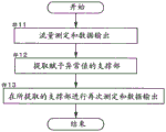
Fig. 9 shows a processing sequence of the first retry mode. As shown in the figure, first, the flow rate measurement device 6 is mounted on one target support portion 22S (step # 01). Then, the flow rate is measured with the flow rate measuring device 6 mounted on the target support portion 22S (# 02). The obtained measurement data is determined whether or not it is controlled within the normal value range (# 03). The normal value range can be, for example, a range of ± 10% with respect to the target flow rate. Of course, the normal value range may be set as appropriate in accordance with the required accuracy.
If the measurement data is determined to be outside the normal value range (# 03: no), the flow rate measurement device 6 is replaced on the same target support 22S by the conveyance device 3(# 04). Then, the flow rate measurement is performed again with the flow rate measurement device 6 mounted on the target support portion 22S (# 05). Such retry after the re-loading is performed until the measured data falls within the normal value range (# 03: yes), or until the number of retries reaches a predetermined set number of times (# 06: yes). The number of times of setting may be appropriately set, but is preferably about 1 to 3 times.
Subsequently, the measurement data in the normal value range or the measurement data after retries only by the set number of times is output to the control section 8 via the first cable 71 (# 07). The control unit 8 records the obtained measurement data in association with the target support portion 22S. In this way, if the flow rate measurement in one of the object support portions 22S is completed, the flow rate measurement device 6 is moved and carried to the other object support portion 22S by the conveyance device 3(# 08). The above-described process sequence is repeatedly executed until the flow rate measurement is completed in all the support portions 22.
In this way, in the first retry mode, when the obtained measurement data deviates from the predetermined normal value range, the control unit 8 (measurement control unit 83) re-measures the flow rate of the purge gas only a predetermined number of times after the flow rate measurement device 6 is mounted on the target support portion 22S again. On the other hand, when the measurement data is controlled to be within the normal value range, the control unit 8 (measurement control unit 83) selects a new support 22 as the target support 22S, moves and carries the flow rate measurement device 6 to the target support 22S, and measures the flow rate of the purge gas. In the first retry mode, even if there is a measurement abnormality due to, for example, an inappropriate load state of the flow rate measurement device 6, it is possible to improve the measurement early by performing a retry every time.
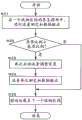
Fig. 10 shows a processing sequence of the second retry mode. As shown in the figure, the flow rate measuring device 6 is sequentially moved and carried to all the support portions 22, and the flow rate is measured in a state where the flow rate measuring device 6 is mounted on each support portion 22 (target support portion 22S), and measurement data is output (# 11). The series of processes corresponds to the repeated execution of the processes of steps # 01, #02, #07, and #08 in the first retry mode. If the flow rate measurement is completed in all the support portions 22, the support portions 22 to which measurement data outside the normal value range is added are extracted (# 12). Then, the flow rate measuring device 6 is sequentially moved and carried to the extracted support portions 22, and the measurement is performed again with the flow rate measuring device 6 being mounted on each support portion 22 (target support portion 22S), and the measurement data is again output (# 13). The control unit 8 replaces the measurement data outside the original normal value range with the latest measurement data obtained for each support unit 22.
In this way, in the second trial mode, the control unit 8 (measurement control unit 83) extracts, as the target support 22S, the support 22 in which the obtained measurement data deviates from the predetermined normal value range from all the supports 22 in which the flow rate of the purge gas is measured. Then, the control unit 8 (measurement control unit 83) sequentially moves and carries the flow rate measuring device 6 to the extracted support portions 22, and sequentially measures the flow rate of the purge gas in each support portion 22. In the second retry mode, measurement data is obtained in all the support portions 22 at an early stage, and even if there is a measurement abnormality due to, for example, an inappropriate loading state of the flow rate measurement device 6, an abnormal value can be efficiently corrected by a retry that is performed at the end.
In each of the above-described inspection modes, a treatment function that can be easily handled when an abnormality of the flow rate adjusting device 43 is suspected may be added. That is, each of the above-described examination modes may include a diagnostic treatment mode for realizing such a treatment function.
Fig. 11 shows a processing procedure of a diagnostic treatment mode performed for each storage section 25. As shown in the drawing, first, the flow rate measurement device 6 is sequentially moved and carried to all the support portions 22 included in one housing section 25, and the flow rate measurement is performed with the flow rate measurement device 6 being mounted on each support portion 22 (target support portion 22S), and measurement data is output (# 21). If the flow rate measurement is completed in all the support portions 22 in the housing section 25, it is determined whether or not the ratio (abnormal ratio) of the support portions 22 to which the measurement data outside the normal value range is added is equal to or greater than a predetermined reference ratio (# 22). The reference ratio may be set as appropriate, but may be, for example, 80%.
If the abnormality ratio is equal to or greater than the reference ratio (# 22: yes), there is a possibility that some abnormality may occur in the flow rate adjustment device 43 provided in association with the housing section 25. Then, in that case, the flow rate adjusting device 43 is started again (# 23). After the restart, if the state of the flow rate adjusting device 43 is stable, all the support portions 22 included in the housing section 25 are measured again and the measurement data is output again (# 24). The control unit 8 replaces the original measurement data with the latest measurement data obtained for each support unit 22. In this way, if the re-measurement of each support portion 22 included in one housing section 25 is completed, the flow rate measuring device 6 is moved and carried to the support portions 22 included in the other housing section 25 by the conveying device 3(# 25).
In this way, in the diagnostic treatment mode, when the measurement data obtained from the number of support portions 22 equal to or larger than the predetermined reference ratio in each housing section 25 deviates from the predetermined normal value range in the housing section 25, the control unit 8 (measurement control unit 83) restarts the flow rate adjustment device 43 assigned to the housing section 25, and the flow rate of the purge gas is measured again in each support portion 22 included in the housing section 25. In the diagnostic treatment mode, it is possible to increase the possibility that an abnormality in the measurement data due to an abnormality in the flow rate adjusting device 43 can be eliminated at an early stage.
(other embodiments)
(1) In the above embodiment, the following configuration is exemplified: the first cable 71 connecting the conveyance device 3 and the flow rate measurement device 6 serves as both a power line and a communication line. However, the configuration is not limited to this, and for example, the first cable 71 may be a dedicated power line, or a dedicated communication line may be provided to connect the conveyance device 3 and the flow rate measurement device 6. Alternatively, when the first cable 71 is a dedicated power line, the conveyance device 3 and the flow rate measurement device 6 may be able to communicate by wireless communication.
(2) In the above embodiment, the following configuration is exemplified: the flow rate measurement system 1 (container housing facility 10) includes a display unit 90, and measurement data of the flow rate measurement device 6 is displayed on the display unit 90 in real time. However, the present invention is not limited to such a configuration, and the measurement data may not be displayed on the display unit 90 in real time. In addition, the display unit 90 may be omitted as appropriate.
(3) In the above embodiment, the following configuration is exemplified: three check modes of a normal mode, a first retry mode, and a second retry mode can be selected. However, the present invention is not limited to such a configuration, and may be configured such that only one or two of these modes can be selected. Further, the mode may be configured to be selectable in a manner other than these modes. As other modes, for example, an analysis mode for finding the cause of a flow rate abnormality, a countermeasure mode for improving the cause by gas purging or scrubbing when a flow rate abnormality occurs, or the like is described.
(4) In the above embodiment, the following configuration is exemplified: each examination mode includes a diagnostic treatment mode. However, the present invention is not limited to such a configuration, and the diagnostic treatment mode may not be included in the at least one examination mode.
(5) In the above embodiment, the following configuration is exemplified: in the first retry mode, when a flow rate abnormality occurs, the flow rate measurement device 6 is newly loaded and re-measurement is performed. However, the present invention is not limited to such a configuration, and may be configured to interrupt the inspection, for example, when a flow rate abnormality occurs. In this case, the alarm may be displayed or sounded to notify the operator of interruption of the inspection due to the flow rate abnormality.
(6) In the above embodiment, the following configuration is exemplified: the container 5 is a small-sized reticle pod accommodating reticles. However, the container 5 is not limited to such a configuration, and may be, for example, a FOUP (Front Opening Unified Pod) that stores a plurality of semiconductor wafers, or may contain food, medical supplies, or the like.
(7) The configurations disclosed in the above-described embodiments (including the above-described embodiments and other embodiments; the same applies hereinafter) can be combined with the configurations disclosed in the other embodiments and applied as long as no contradiction occurs. Other configurations are also exemplified in all the points of the embodiments disclosed in the present specification, and can be changed as appropriate without departing from the spirit of the present disclosure.
(outline of embodiment)
In summary, the flow rate measurement system according to the present disclosure preferably includes the following respective configurations.
A container storage facility for measuring a flow rate of a purge gas supplied from a gas supply device by using a flow rate measuring device, the container storage facility comprising: a storage rack having a plurality of support portions; a conveying device for conveying a container to a target support selected from the plurality of supports; and the gas supply device that supplies the purge gas to the container supported by each of the plurality of support portions, characterized in that,
the conveyance device and the flow rate measurement device are connected to each other via a power line in a communicable state,
the flow rate measuring device measures the flow rate of the purge gas in a state where the conveying device conveys the flow rate measuring device in place of the container and the flow rate measuring device is mounted on the target support portion.
According to this configuration, since the flow rate is measured in the same state as the state in which the container is supported by the support portion in the state in which the flow rate measuring device is mounted on the object support portion, the flow rate of the purge gas to be supplied can be measured with high accuracy. In addition, in general, when a transport device that transports a container is connected to, for example, an electric power system and is constantly supplied with electric power, the transport device and the flow rate measurement device are connected via an electric power line, and therefore, electric power is also stably supplied to the flow rate measurement device via the transport device. Therefore, battery replacement, which is problematic in the case where power is supplied from, for example, a small battery to the flow rate measurement device, is not necessary, and data measurement can be performed efficiently. In addition, in general, when a transport device that transports containers is communicably connected to a control device, since the transport device and the flow rate measurement device can communicate with each other, measurement data obtained by the flow rate measurement device can be sequentially transmitted to the control device via the transport device. Therefore, the merging processing of the measurement data on the control device side, which is a problem in the case of performing flow rate measurement in a plurality of batches, is not necessary, and the entire set of measurement data can be obtained efficiently.
In one aspect, it is preferable that,
the container storage facility further includes: a control unit that controls operations of the conveyance device and the gas supply device; and a display part, wherein the display part is provided with a display screen,
the measurement data of the flow rate measurement device is transmitted to the control unit in real time,
the control unit displays the received measurement data on the display unit.
According to this configuration, the operator can be notified of the measurement data during the measurement in real time, or the measurement data after the measurement can be notified without delay. Therefore, the operator can determine the approximate appropriateness of the measurement data at an early stage. For example, when the measurement data is abnormal immediately after the start of the examination, measures such as interrupting the measurement and reviewing the entire system can be taken. As a result, even if there is an abnormality, it is possible to improve the abnormality early, and from this point of view, the entire set of measurement data can be obtained efficiently.
In one aspect, it is preferable that,
the container storage facility further includes a control unit that controls operations of the conveying device and the gas supply device,
the measurement data of the flow rate measurement device is transmitted to the control unit in real time,
the control unit may be configured to re-measure the flow rate of the purge gas only a predetermined number of times after the flow rate measuring device is newly mounted on the target support unit when the obtained measurement data deviates from a predetermined normal value range, and to select a new support unit as the target support unit when the measurement data is controlled within the normal value range, and to move and mount the flow rate measuring device to the target support unit to measure the flow rate of the purge gas.
According to this configuration, the procedure of moving and carrying the flow rate measuring device to a new support and measuring the flow rate of the purge gas is repeated on the condition that the measurement data is controlled within the normal value range, whereby the data measurement and the determination of the propriety thereof can be automated, and the entire set of measurement data can be efficiently obtained. When the measurement data deviates from the normal value range, the measurement is performed again after the flow rate measurement device is reloaded, and therefore even if there is a measurement abnormality due to, for example, an improper loading state, it is possible to improve the measurement early by performing a retry every time.
In one aspect, it is preferable that,
the container storage facility further includes a control unit that controls operations of the conveying device and the gas supply device,
the measurement data of the flow rate measurement device is transmitted to the control unit,
the control unit extracts the support part, of which the obtained measurement data is deviated from a predetermined normal value range, from all the support parts that have measured the flow rate of the purge gas, and sequentially moves and carries the flow rate measurement device to the extracted support part as the target support part, and sequentially measures the flow rate of the purge gas in each support part.
According to this configuration, the flow rate of the inert gas in the support portion in which the measurement data deviates from the normal value range can be measured again in a unified manner. Therefore, even if measurement data is obtained early in all the support sections and measurement abnormality occurs due to, for example, an inappropriate load state, the abnormal value can be corrected efficiently by retry that is performed at the end.
In one aspect, it is preferable that,
the receiving rack is divided into a plurality of receiving sections respectively including a plurality of the supporting parts,
the gas supply device is configured to supply the purge gas, the flow rate of which is adjusted by a common flow rate adjustment device, in parallel to the plurality of support portions included in one housing section,
the container storage facility further includes a control unit that controls operations of the conveying device and the gas supply device,
the measurement data of the flow rate measurement device is transmitted to the control unit in real time,
the control unit restarts the flow rate adjusting device assigned to the storage section when the measured data obtained from the number of the support units equal to or larger than a predetermined reference ratio in the storage section deviates from a predetermined normal value range, and re-measures the flow rate of the purge gas in each support unit included in the storage section.
When the measured data obtained in the support portion having a standard ratio or more among the plurality of support portions in the housing section deviates from the normal value range, there is a possibility that some abnormality occurs in the flow rate adjusting device commonly used for those support portions. In this regard, according to the above configuration, in such a case, since the flow rate adjusting device is restarted in the housing section and then remeasured in each support portion, it is possible to eliminate early the possibility of abnormality of the measurement data due to abnormality of the flow rate adjusting device.
In one aspect, it is preferable that,
the control unit prohibits the conveyance operation of the conveyance device during the measurement of the flow rate of the purge gas by the flow rate measurement device.
According to this configuration, in the flow rate measurement by the flow rate measurement device, it is possible to avoid a situation in which the power line between the conveyance device and the flow rate measurement device is disconnected due to the movement of the conveyance device.
In one aspect, it is preferable that,
at least one of the length of the power line, the thickness of the power line, and the fixed position of the power line is set so that the load acting on the target support section is equal to the load due to the self weight of the flow rate measurement device.
According to this configuration, even when the conveying device and the flow rate measuring device are connected by the power line, the load of the flow rate measuring device acting on the target support portion can be hardly affected. Therefore, the flow rate of the purge gas can be accurately measured in a state where only a load substantially equal to the load due to the own weight of the flow rate measuring device acts on the target support portion.
The flow rate measurement system according to the present disclosure may exhibit at least one of the above-described effects.
Description of the symbols
1 flow rate measuring system
2 storage rack
3 conveying device
4 gas supply device
5 Container
6 flow rate measuring device
8 control part
10 container storage facility
22 support part
22S object support
25 receiving section
43 flow rate adjusting device
71 first cable (Power line)
And 90 a display part.
Claims (7)
1. A flow rate measurement system for measuring a flow rate of purge gas supplied from a gas supply device by using a flow rate measurement device in a container storage facility, the container storage facility comprising: a storage rack having a plurality of support portions; a conveying device for conveying a container to a target support selected from the plurality of supports; and the gas supply device that supplies the purge gas to the container supported by each of the plurality of support portions, characterized in that,
the conveyance device and the flow rate measurement device are connected to each other via a power line in a communicable state,
the flow rate measuring device measures the flow rate of the purge gas in a state where the conveying device conveys the flow rate measuring device in place of the container and the flow rate measuring device is mounted on the target support portion.
2. The flow rate measurement system according to claim 1,
the container storage facility further includes: a control unit that controls operations of the conveyance device and the gas supply device; and a display part, wherein the display part is provided with a display screen,
the measurement data of the flow rate measurement device is transmitted to the control unit in real time,
the control unit displays the received measurement data on the display unit.
3. The flow rate measuring system according to claim 1 or 2,
the container storage facility further includes a control unit that controls operations of the conveying device and the gas supply device,
the measurement data of the flow rate measurement device is transmitted to the control unit in real time,
the control unit may be configured to re-measure the flow rate of the purge gas only a predetermined number of times after the flow rate measuring device is newly mounted on the target support unit when the obtained measurement data deviates from a predetermined normal value range, and to select a new support unit as the target support unit when the measurement data is controlled within the normal value range, and to move and mount the flow rate measuring device to the target support unit to measure the flow rate of the purge gas.
4. The flow rate measuring system according to claim 1 or 2,
the container storage facility further includes a control unit that controls operations of the conveying device and the gas supply device,
the measurement data of the flow rate measurement device is transmitted to the control unit,
the control unit extracts the support part, of which the obtained measurement data is deviated from a predetermined normal value range, from all the support parts that have measured the flow rate of the purge gas, and sequentially moves and carries the flow rate measurement device to the extracted support part as the target support part, and sequentially measures the flow rate of the purge gas in each support part.
5. Flow rate measuring system according to any of claims 1 or 2,
the receiving rack is divided into a plurality of receiving sections respectively including a plurality of the supporting parts,
the gas supply device is configured to supply the purge gas, the flow rate of which is adjusted by a common flow rate adjustment device, in parallel to the plurality of support portions included in one housing section,
the container storage facility further includes a control unit that controls operations of the conveying device and the gas supply device,
the measurement data of the flow rate measurement device is transmitted to the control unit in real time,
the control unit restarts the flow rate adjusting device assigned to the storage section when the measured data obtained from the number of the support units equal to or larger than a predetermined reference ratio in the storage section deviates from a predetermined normal value range, and re-measures the flow rate of the purge gas in each support unit included in the storage section.
6. The flow rate measurement system according to claim 2,
the control unit prohibits the conveyance operation of the conveyance device during the measurement of the flow rate of the purge gas by the flow rate measurement device.
7. The flow rate measuring system according to claim 1 or 2,
at least one of the length of the power line, the thickness of the power line, and the fixed position of the power line is set so that the load acting on the target support section is equal to the load due to the self weight of the flow rate measurement device.
Applications Claiming Priority (2)
| Application Number | Priority Date | Filing Date | Title |
|---|---|---|---|
| JP2017021571A JP6614174B2 (en) | 2017-02-08 | 2017-02-08 | Flow measurement system |
| JP2017-021571 | 2017-02-08 |
Publications (2)
| Publication Number | Publication Date |
|---|---|
| CN108398168A CN108398168A (en) | 2018-08-14 |
| CN108398168B true CN108398168B (en) | 2021-02-19 |
Family
ID=63037084
Family Applications (1)
| Application Number | Title | Priority Date | Filing Date |
|---|---|---|---|
| CN201810122409.9A Active CN108398168B (en) | 2017-02-08 | 2018-02-07 | Flow rate measuring system |
Country Status (4)
| Country | Link |
|---|---|
| US (1) | US10502605B2 (en) |
| JP (1) | JP6614174B2 (en) |
| KR (1) | KR102564752B1 (en) |
| CN (1) | CN108398168B (en) |
Families Citing this family (3)
| Publication number | Priority date | Publication date | Assignee | Title |
|---|---|---|---|---|
| JP6414525B2 (en) * | 2015-09-02 | 2018-10-31 | 株式会社ダイフク | Storage facilities |
| US20230108771A1 (en) * | 2020-03-09 | 2023-04-06 | Murata Machinery, Ltd. | Flatness measurement unit |
| KR102593950B1 (en) * | 2021-12-29 | 2023-10-24 | 세메스 주식회사 | Flow supply apparatus and supply method |
Citations (5)
| Publication number | Priority date | Publication date | Assignee | Title |
|---|---|---|---|---|
| CN201392230Y (en) * | 2009-04-20 | 2010-01-27 | 浙江灵铭管道科技有限公司 | Flow capacity detecting and verifying device of water separators |
| CN103193051A (en) * | 2012-01-04 | 2013-07-10 | 株式会社大福 | Article storage facility and article storage method |
| CN104215282A (en) * | 2013-05-30 | 2014-12-17 | 中国石油化工股份有限公司 | Gas flow measuring device and method for measuring gas flow using same |
| CN104253073A (en) * | 2013-06-28 | 2014-12-31 | 株式会社日立国际电气 | Substrate processing apparatus, method of manufacturing semiconductor device and flow monitoring method |
| US20150000372A1 (en) * | 2013-06-26 | 2015-01-01 | Daifuku Co., Ltd. | Inspection Apparatus for Article Storage Facility |
Family Cites Families (11)
| Publication number | Priority date | Publication date | Assignee | Title |
|---|---|---|---|---|
| JPH07209037A (en) * | 1994-01-21 | 1995-08-11 | Tatsuno Co Ltd | Flow meter |
| JP3590341B2 (en) * | 2000-10-18 | 2004-11-17 | 東京エレクトロン株式会社 | Temperature measuring device and temperature measuring method |
| EP2035320A4 (en) * | 2006-06-19 | 2010-07-28 | Entegris Inc | System for purging reticle storage |
| JP4670808B2 (en) * | 2006-12-22 | 2011-04-13 | ムラテックオートメーション株式会社 | Container transport system and measuring container |
| JP5236518B2 (en) * | 2009-02-03 | 2013-07-17 | 株式会社ダン・タクマ | Storage system and storage method |
| KR101207112B1 (en) * | 2010-07-27 | 2012-12-03 | 주식회사 포스코 | Measuring apparatus for quantity of sprayed water |
| KR101680165B1 (en) * | 2013-03-05 | 2016-11-28 | 무라다기카이가부시끼가이샤 | Measurement unit and purge gas flow rate measuring method |
| JP5892113B2 (en) * | 2013-06-26 | 2016-03-23 | 株式会社ダイフク | Goods storage facility |
| JP6409579B2 (en) * | 2015-01-08 | 2018-10-24 | 村田機械株式会社 | Purge stocker and operation method of purge stocker |
| WO2016129170A1 (en) * | 2015-02-12 | 2016-08-18 | 村田機械株式会社 | Purge device, purge stocker, and purge abnormality detection method |
| KR101748361B1 (en) * | 2015-04-29 | 2017-06-19 | (주)젠스엠 | Apparatus for supplying gas for wafer container |
-
2017
- 2017-02-08 JP JP2017021571A patent/JP6614174B2/en active Active
-
2018
- 2018-02-07 CN CN201810122409.9A patent/CN108398168B/en active Active
- 2018-02-07 KR KR1020180015071A patent/KR102564752B1/en active IP Right Grant
- 2018-02-08 US US15/891,635 patent/US10502605B2/en active Active
Patent Citations (5)
| Publication number | Priority date | Publication date | Assignee | Title |
|---|---|---|---|---|
| CN201392230Y (en) * | 2009-04-20 | 2010-01-27 | 浙江灵铭管道科技有限公司 | Flow capacity detecting and verifying device of water separators |
| CN103193051A (en) * | 2012-01-04 | 2013-07-10 | 株式会社大福 | Article storage facility and article storage method |
| CN104215282A (en) * | 2013-05-30 | 2014-12-17 | 中国石油化工股份有限公司 | Gas flow measuring device and method for measuring gas flow using same |
| US20150000372A1 (en) * | 2013-06-26 | 2015-01-01 | Daifuku Co., Ltd. | Inspection Apparatus for Article Storage Facility |
| CN104253073A (en) * | 2013-06-28 | 2014-12-31 | 株式会社日立国际电气 | Substrate processing apparatus, method of manufacturing semiconductor device and flow monitoring method |
Non-Patent Citations (1)
| Title |
|---|
| 插入式阵列电导传感器两相流测量方法研究;郑桂波;《中国博士学位论文全文数据库 工程科技2辑》;20121231(第12期);第C030-8页 * |
Also Published As
| Publication number | Publication date |
|---|---|
| JP6614174B2 (en) | 2019-12-04 |
| CN108398168A (en) | 2018-08-14 |
| KR20180092288A (en) | 2018-08-17 |
| JP2018129400A (en) | 2018-08-16 |
| KR102564752B1 (en) | 2023-08-08 |
| US10502605B2 (en) | 2019-12-10 |
| US20180224311A1 (en) | 2018-08-09 |
Similar Documents
| Publication | Publication Date | Title |
|---|---|---|
| CN108398168B (en) | Flow rate measuring system | |
| US10438829B2 (en) | Purge device and purge method | |
| US9230845B2 (en) | Article storage facility and article storage method | |
| US7918122B2 (en) | Container transport system and measurement container | |
| US8942844B2 (en) | Article storage facility and article storage method | |
| TWI780689B (en) | Service tunnel for use on capital equipment in semiconductor manufacturing and research fabs | |
| US11067624B2 (en) | Inspection system | |
| JP6409579B2 (en) | Purge stocker and operation method of purge stocker | |
| US20100152887A1 (en) | Substrate processing apparatus and display method for substrate processing apparatus | |
| WO2017022330A1 (en) | Purge device, purge stocker, and method for feeding purge gas | |
| CN105584769A (en) | Article storage facility | |
| JP6217281B2 (en) | Automatic warehouse and gas supply method | |
| JP2013171872A (en) | Substrate processing device and substrate processing method | |
| KR20200028303A (en) | Substrate processing apparatus and purging method | |
| JP7246256B2 (en) | Conveying method and conveying system | |
| CN114664692A (en) | Substrate transfer apparatus, substrate processing system, and substrate processing method | |
| KR100819098B1 (en) | Furnace semiconductor prodution device having transfer process function of lot unit and method for processing transfer therefor | |
| KR102663006B1 (en) | Apparatus for storing carriers | |
| JP7277813B2 (en) | Conveying system and container opening/closing device | |
| CN115995412A (en) | Substrate conveying device and substrate conveying method | |
| JP2024048171A (en) | Lifter pin control method and transfer arm | |
| CN117882182A (en) | Purge system | |
| JP2010225617A (en) | Substrate processing system | |
| KR20140072647A (en) | Inspection method of Apparatus for Processing Substrate | |
| KR20160147692A (en) | Apparatus for Processing Substrate |
Legal Events
| Date | Code | Title | Description |
|---|---|---|---|
| PB01 | Publication | ||
| PB01 | Publication | ||
| SE01 | Entry into force of request for substantive examination | ||
| SE01 | Entry into force of request for substantive examination | ||
| GR01 | Patent grant | ||
| GR01 | Patent grant |