Be used for building steel form release agent to paint device
Technical Field
The invention relates to the technical field of buildings, in particular to a device for smearing a release agent for a building steel template.
Background
The steel template also called as a non-dismantling template net can replace a wood template, so that the elimination of the pore water pressure and air bubbles in the concrete pressure by the conventional sealing templates such as wood, plywood or steel plates is obviously reduced; and (3) pouring and forming concrete of a steel template (a template net without dismantling) structure.
The release agent is a functional substance between the mold and the finished product. According to the chemical components of the release agent, the release agent can be divided into three types of inorganic substances, organic substances and high polymers. The release agent is chemically resistant and does not dissolve when in contact with the chemical components of different resins, particularly styrene and amines. The release agent also has heat resistance and stress resistance, and is not easy to decompose or wear; the release agent adheres to the mold without transferring to the part being processed, and does not interfere with painting or other secondary processing operations. The release agent acts to separate the cured composite article from the mold only smoothly, resulting in a smooth, flat article and a substance that ensures repeated use of the mold. The amount of release agent used is also greatly increased due to the rapid development of injection molding, extrusion, calendering, molding, lamination and other processes.
When the concrete of the building engineering is constructed, the surface of the template needs to be coated with a release agent so as to be convenient for the removal of the concrete template. The existing release agent is used for smearing a steel template, the template is arranged on a table top and is smeared, the smearing effect is influenced when the steel template is easy to deviate or the steel template is moved due to the external factors, so that the working efficiency is increased, the steel template is smeared manually, the efficiency is low, a small amount of automatic machines are arranged on the market, the structure is not perfect, an improved space exists, the thickness of the release agent is uneven after being brushed, the construction of a concrete building is caused, the color of the outer surface is uneven, and the construction process has deviation.
Based on the technical scheme, the invention designs the release agent smearing device for the building steel formwork to solve the problems.
Disclosure of Invention
The invention aims to provide a device for smearing a release agent on a building steel template, which aims to solve the problems that the template proposed in the background technology is arranged on a table top and smeared, and the smearing effect is influenced when the steel template is easy to deviate or move due to the outside, so that the working efficiency is increased, then the efficiency is low, smearing is performed by manual smearing through manual smearing, the efficiency is low, a small number of automatic machines are arranged on the market, but the structure is not perfect, and an improved space exists, so that the thickness of the release agent is uneven after the release agent is smeared.
In order to achieve the purpose, the invention provides the following technical scheme: a device for smearing a release agent on a building steel template, which comprises a frame body, a mounting top plate, a workpiece table and a smearing mechanism, the mounting top plate is fixedly mounted at the top of the frame body, through grooves are formed in both sides of the outer wall of the frame body, the workpiece table is positioned in the frame body, two groups of lifting rollers are arranged at two ends of the workpiece table, the lifting roller wheels are positioned at the outer sides of the through grooves, the two ends of the top of the mounting top plate are both provided with a lifting motor, a tension roller is arranged above the through groove, the power output end of the lifting motor is respectively connected with the tension roller and the lifting roller through a traction rope, the bottom of the mounting top plate is provided with a sliding track, the bottom of the sliding track is connected with a moving plate in a sliding way, the hydraulic cylinder is installed to the inner chamber right wall of support body, the flexible end of hydraulic cylinder and the outer wall fixed connection of movable plate, paint the bottom at the movable plate at the mechanism installation.
Preferably, the workpiece platform comprises a movable bottom plate and a workpiece mounting plate, the workpiece mounting plate is fixedly mounted at the top of the movable bottom plate, positioning holes are formed in the middle of the workpiece mounting plate, protruding blocks are arranged at four corners of the workpiece mounting plate, positioning bolts are screwed in the protruding blocks, and positioning frames are fixedly connected to the top ends of the positioning bolts.
Preferably, the positioning frame is L-shaped.
Preferably, the outer wall both sides of removing the bottom plate all are equipped with the spliced pole, the fixed cover of promotion running roller is in the outside of spliced pole, the removal slider has been cup jointed to the inboard of spliced pole, remove the slider and lead to the groove phase-match.
Preferably, paint the mechanism and include the aircraft bonnet, a lateral wall fixed mounting of aircraft bonnet has the workbin, the inner chamber top fixed mounting of aircraft bonnet has the motor, the inner chamber bottom of aircraft bonnet is equipped with the groove that gathers materials, the lateral wall that gathers materials the groove is through slip sand grip sliding connection in the inside of aircraft bonnet, the agitator has been cup jointed to the output of motor, and the agitator is located the inside that gathers materials the groove.
Preferably, be connected with the connecting plate between the outer wall of motor and the inner wall one side of aircraft bonnet, the material sprayer is installed in the bottom slope of connecting plate, the workbin passes through output pipeline and material sprayer intercommunication setting, the bottom of collecting tank has cup jointed the brush of smearing, another lateral wall of aircraft bonnet has opened the heat dissipation window.
Preferably, the rear side wall of the frame body is provided with an installation support plate, the inside of the installation support plate is screwed with a fixing bolt, the front end of the fixing bolt is fixedly provided with a fixing clamp, one side of the inside of the fixing clamp is screwed with a compression bolt, one end of the compression bolt is provided with a compression plate, and the compression plate is located inside the fixing clamp.
Compared with the prior art, the invention has the beneficial effects that: the lifting motor lifts the workpiece table through the traction rope, the phenomenon that when the steel formwork is smeared, the steel formwork deviates or the steel formwork moves due to the outside is avoided, the smearing effect is affected, the steel formwork is lifted stably, then when smearing is conducted, the motor drives the stirrer to stir the release agent in the material collecting groove, the adhesion of the release agent to the steel formwork is avoided, the smearing uniformity is improved, the stirred release agent overflows from the smearing brush, the thickness of the release agent after smearing is uniform, the steel formwork is smeared, the smearing work of the release agent on the steel formwork is achieved, then the smearing mechanism arranged on the moving plate is moved through the hydraulic cylinder, the release agent is evenly smeared on the steel formwork, the smearing efficiency is high, and the concrete building construction process is more accurate.
Drawings
In order to more clearly illustrate the technical solutions of the embodiments of the present invention, the drawings used in the description of the embodiments will be briefly introduced below, and it is obvious that the drawings in the following description are only some embodiments of the present invention, and it is obvious for those skilled in the art that other drawings can be obtained according to the drawings without creative efforts.
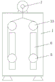
FIG. 1 is a schematic structural view of the present invention;
FIG. 2 is a side view of the present invention;
FIG. 3 is a schematic view of a stage according to the present invention;
FIG. 4 is a schematic view of the structure of the coating mechanism of the present invention;
FIG. 5 is an enlarged view of part A of the present invention.
In the drawings, the components represented by the respective reference numerals are listed below:
1-frame body, 2-installation top plate, 3-workpiece table, 31-moving bottom plate, 32-workpiece installation plate, 33-positioning hole, 34-lug, 35-positioning bolt, 36-positioning frame, 37-connecting column, 38-moving slide block, 4-smearing mechanism, 41-hood, 42-bin, 43-motor, 44-connecting plate, 45-sprayer, 46-collecting groove, 47-sliding convex strip, 48-smearing brush, 49-heat dissipation window, 5-lifting roller, 6-through groove, 7-lifting motor, 8-traction rope, 9-sliding rail, 10-moving plate, 11-hydraulic cylinder, 12-installation support plate, 121-fixing clamp, 122-fixing bolt, 123-pressing plate, 124-compression bolts and 13-tensioning rollers.
Detailed Description
The technical solutions in the embodiments of the present invention will be clearly and completely described below with reference to the drawings in the embodiments of the present invention, and it is obvious that the described embodiments are only a part of the embodiments of the present invention, and not all of the embodiments. All other embodiments, which can be derived by a person skilled in the art from the embodiments given herein without making any creative effort, shall fall within the protection scope of the present invention.
Referring to fig. 1-5, the present invention provides a technical solution: a device for smearing a release agent for a building steel template comprises a frame body 1, a mounting top plate 2, a workpiece table 3 and a smearing mechanism 4, wherein the mounting top plate 2 is fixedly mounted at the top of the frame body 1, through grooves 6 are formed in two sides of the outer wall of the frame body 1, the workpiece table 3 is located inside the frame body 1, two groups of lifting rollers 5 are arranged at two ends of the workpiece table 3, the lifting rollers 5 are located on the outer sides of the through grooves 6, lifting motors 7 are mounted at two ends of the top of the mounting top plate 2, tensioning rollers 13 are mounted above the through grooves 6, the power output end of the lifting motors 7 is respectively connected with the tensioning rollers 13 and the lifting rollers 5 through traction ropes 8, a sliding rail 9 is mounted at the bottom of the mounting top plate 2, a movable plate 10 is slidably connected to the bottom of the sliding rail 9, a hydraulic cylinder 11 is mounted on the right wall of an, the smearing mechanism 4 is mounted at the bottom of the moving plate 10.
Wherein, the workpiece table 3 comprises a movable bottom plate 31 and a workpiece mounting plate 32, the workpiece mounting plate 32 is fixedly mounted on the top of the movable bottom plate 31, a positioning hole 33 is arranged in the middle of the workpiece mounting plate 32 and is used for positioning a steel template, four corners of the workpiece mounting plate 32 are provided with bumps 34, the bumps 34 are screwed with positioning bolts 35, the top ends of the positioning bolts 35 are fixedly connected with positioning frames 36, the positioning frames 36 are L-shaped, the steel template is arranged on the workpiece mounting plate 32, then the four groups of positioning frames 26 are controlled to rotate through manually adjusting the positioning bolts 35 to realize the positioning and fixing of the steel template, two sides of the outer wall of the movable bottom plate 31 are provided with connecting columns 37, the lifting rollers 5 are fixedly sleeved on the outer sides of the connecting columns 37, the inner sides of the connecting columns 37 are sleeved with movable sliders 38, the movable sliders 38 are matched with the through grooves 6, when the movable bottom plate, the movable bottom plate 31 is matched with the through groove 6 through the movable sliding block 38, the movable bottom plate can be stably moved, the smearing mechanism 4 comprises a hood 41, a material box 42 is fixedly installed on one side wall of the hood 41, a motor 43 is fixedly installed on the top of an inner cavity of the hood 41, a material collecting groove 46 is arranged at the bottom of the inner cavity of the hood 41, the outer side wall of the material collecting groove 46 is connected to the inside of the hood 41 in a sliding mode through a sliding protruding strip 47, a stirrer is sleeved at the output end of the motor 43 and located inside the material collecting groove 46, a connecting plate 44 is connected between the outer wall of the motor 43 and one side of the inner wall of the hood 41, a material sprayer 45 is obliquely installed at the bottom of the connecting plate 44, the material box 42 is communicated with the material sprayer 45 through an output pipeline, a smearing brush 48 is sleeved at the bottom of the material collecting groove 46, when smearing is, then the motor 43 is powered on, the motor 43 drives the stirrer to stir the release agent in the material collecting groove 46 to avoid adhesion, the smearing uniformity is improved, the stirred release agent overflows from the smearing brush 48 to achieve painting and smearing work on the steel template, the other side of the outer wall of the smearing brush 41 is provided with a heat dissipation window 49 which plays a good heat dissipation role for the motor 43, the rear side wall of the frame body 1 is provided with the installation support plate 12, the inside of the installation support plate 12 is screwed with the fixing bolt 122, the front end of the fixing bolt 122 is fixedly provided with the fixing clamp 121, one side of the inside of the fixing clamp 121 is screwed with the compression bolt 124, one end of the compression bolt 124 is provided with the compression plate 123, the compression plate 123 is positioned inside the fixing clamp 121, before smearing, the steel template installed on the workpiece table 3 is moved to one side of the frame body 1, and then the fixing bolt 122 and the compression bolt 124 are respectively adjusted, remove fixation clamp 121 and pressure strip 123 to the realization is fixed workpiece table 3, avoids when paining the steel form, and the steel form takes place the skew or when the external steel form that leads to removes, and the effect is paintd in the influence, thereby has increased work efficiency.
One specific application of this embodiment is: when the device works, the steel template is stably fixed on the workpiece mounting plate 32 through the positioning hole 33 and the positioning frame 36 to realize positioning and fixing of the steel template, the stability of the steel template during moving is improved, then the lifting motor 7 is powered on, the lifting motor 7 lifts the workpiece table 3 through the traction rope 8 and lifts the workpiece table to one side of the mounting support plate 12, then the fixing bolt 122 and the pressing bolt 124 are respectively adjusted to fix the position of the workpiece table 3, so that the stability of coating the release agent is greatly improved, during coating, the valves on the motor 43 and the material box 42 are respectively started, the release agent is sprayed into the collecting groove 46 from the material sprayer 45 through an output pipeline, the motor 43 drives the stirrer to stir the release agent in the collecting groove 46, the adhesion of the release agent is avoided, the coating uniformity is improved, and the stirred release agent overflows from the coating brush 48, therefore, the thickness of the release agent is uniform after the release agent is coated, so that the coating work on the steel template is realized, the coating mechanism 4 arranged on the moving plate 10 is moved through the hydraulic cylinder 11, the release agent is uniformly coated on the steel template, and the coating efficiency is high.
In the description herein, references to the description of "one embodiment," "an example," "a specific example" or the like are intended to mean that a particular feature, structure, material, or characteristic described in connection with the embodiment or example is included in at least one embodiment or example of the invention. In this specification, the schematic representations of the terms used above do not necessarily refer to the same embodiment or example. Furthermore, the particular features, structures, materials, or characteristics described may be combined in any suitable manner in any one or more embodiments or examples.
The preferred embodiments of the invention disclosed above are intended to be illustrative only. The preferred embodiments are not intended to be exhaustive or to limit the invention to the precise embodiments disclosed. Obviously, many modifications and variations are possible in light of the above teaching. The embodiments were chosen and described in order to best explain the principles of the invention and the practical application, to thereby enable others skilled in the art to best utilize the invention. The invention is limited only by the claims and their full scope and equivalents.