CN108340061B - Flexibly controlled butt-welding equipment - Google Patents
Flexibly controlled butt-welding equipment Download PDFInfo
- Publication number
- CN108340061B CN108340061B CN201810144832.9A CN201810144832A CN108340061B CN 108340061 B CN108340061 B CN 108340061B CN 201810144832 A CN201810144832 A CN 201810144832A CN 108340061 B CN108340061 B CN 108340061B
- Authority
- CN
- China
- Prior art keywords
- auxiliary material
- welding
- feeding
- main material
- main
- Prior art date
- Legal status (The legal status is an assumption and is not a legal conclusion. Google has not performed a legal analysis and makes no representation as to the accuracy of the status listed.)
- Active
Links
- 238000003466 welding Methods 0.000 title claims abstract description 180
- 239000000463 material Substances 0.000 claims abstract description 431
- 230000007246 mechanism Effects 0.000 claims abstract description 123
- 238000007599 discharging Methods 0.000 claims abstract description 17
- 238000002360 preparation method Methods 0.000 claims description 27
- 238000000034 method Methods 0.000 claims description 18
- 230000008569 process Effects 0.000 claims description 16
- 238000009413 insulation Methods 0.000 claims description 6
- 238000010030 laminating Methods 0.000 claims description 3
- 230000003044 adaptive effect Effects 0.000 claims description 2
- 238000003754 machining Methods 0.000 abstract description 2
- 239000004615 ingredient Substances 0.000 description 14
- 239000002075 main ingredient Substances 0.000 description 6
- 230000032258 transport Effects 0.000 description 3
- 239000002184 metal Substances 0.000 description 2
- 238000012986 modification Methods 0.000 description 2
- 230000004048 modification Effects 0.000 description 2
- NJPPVKZQTLUDBO-UHFFFAOYSA-N novaluron Chemical compound C1=C(Cl)C(OC(F)(F)C(OC(F)(F)F)F)=CC=C1NC(=O)NC(=O)C1=C(F)C=CC=C1F NJPPVKZQTLUDBO-UHFFFAOYSA-N 0.000 description 2
- 230000009471 action Effects 0.000 description 1
- 239000000126 substance Substances 0.000 description 1
Images


Classifications
-
- B—PERFORMING OPERATIONS; TRANSPORTING
- B23—MACHINE TOOLS; METAL-WORKING NOT OTHERWISE PROVIDED FOR
- B23K—SOLDERING OR UNSOLDERING; WELDING; CLADDING OR PLATING BY SOLDERING OR WELDING; CUTTING BY APPLYING HEAT LOCALLY, e.g. FLAME CUTTING; WORKING BY LASER BEAM
- B23K11/00—Resistance welding; Severing by resistance heating
- B23K11/36—Auxiliary equipment
Abstract
The invention relates to the field of machining, and provides flexible control butt-welding equipment which comprises a main body, and a main material feeding mechanism, an auxiliary material feeding mechanical arm, a main material discharging mechanism, an auxiliary material preparing mechanism and a welding mechanism which are arranged on the main body, wherein the main material feeding mechanism is used for conveying a main material to a welding position, the auxiliary material preparing mechanism is used for conveying the auxiliary material to the preparing position, the auxiliary material feeding mechanical arm is used for conveying the auxiliary material at the preparing position to the welding position, the welding mechanism is used for welding the auxiliary material to the main material, and the main material discharging mechanism is used for conveying the main material away from the welding position. The flexible control butt-welding equipment can realize automatic welding of workpieces, improve the working efficiency, reduce the working cost, and simultaneously improve the working precision, and the reliability and the stability of the whole device are higher.
Description
Technical Field
The invention relates to the field of machining, in particular to flexibly controlled butt-welding equipment.
Background
In the prior art, the welding device has low automation degree, and needs manual operation or can only be operated semi-automatically. Or some automatic welding devices have lower precision and poorer reliability.
Therefore, it is necessary to provide a new automatic welding device to solve the above problems.
Disclosure of Invention
The invention provides a novel flexible control butt-welding device which can realize automatic and accurate welding operation.
The invention provides flexibly controlled butt-welding equipment which is used for welding main materials and auxiliary materials together and comprises a main body, and a main material feeding mechanism, an auxiliary material feeding mechanical arm, a main material discharging mechanism, an auxiliary material preparing mechanism, a welding mechanism and a flexible laminating mechanism which are arranged on the main body. The main material feeding mechanism is used for conveying the main material to a welding position, the auxiliary material preparing mechanism is used for conveying the auxiliary material to a material preparing position, the auxiliary material feeding manipulator is used for conveying the auxiliary material at the material preparing position to the welding position, the welding mechanism is used for welding the auxiliary material to the main material, the main material discharging mechanism is used for conveying the main material away from the welding position, and the flexible attaching mechanism A1 is used for eliminating a gap between the main material 80 and the welding mechanism 70 and improving the welding precision and quality;
the main material feeding mechanism comprises a main material feeding cylinder, a main material standby material frame and a main material feeding rod, wherein the main material standby material frame comprises two main material standby material side walls and a main material bracket connected with the two main material standby material side walls, and the main material feeding rod is fixedly connected with a piston rod of the main material feeding cylinder and is slidably arranged on the main material bracket;
the auxiliary material preparing mechanism comprises an auxiliary material preparing frame, an auxiliary material preparing cylinder and an auxiliary material preparing rod, the auxiliary material preparing frame comprises an auxiliary material preparing frame and an auxiliary material bracket, the auxiliary material bracket comprises a supporting section and a conveying section, the supporting section is provided with a concave groove, the auxiliary material preparing rod can slide in the concave groove, and a piston rod of the auxiliary material cylinder is fixedly connected with the auxiliary material preparing rod;
the auxiliary material feeding manipulator comprises a transverse feeding cylinder, a transverse feeding connecting piece, a longitudinal feeding cylinder, a longitudinal feeding connecting piece, a vertical feeding cylinder, a vertical feeding connecting piece, a feeding clamping cylinder and a feeding jaw, wherein the transverse feeding connecting piece is fixedly connected to a piston rod of the transverse feeding cylinder, and the longitudinal feeding cylinder is fixedly connected with the transverse feeding connecting piece;
the longitudinal feeding connecting piece is fixedly connected to a piston rod of the longitudinal feeding cylinder, the vertical feeding cylinder is fixedly connected with the longitudinal feeding connecting piece, the vertical feeding connecting piece is fixedly connected to the piston rod of the vertical feeding cylinder, and the feeding clamping cylinder is fixedly arranged on the vertical feeding connecting piece and used for driving the feeding jaw to clamp the auxiliary material;
the flexible attaching mechanism comprises an insulation main body, a guide sliding rod movably connected with the insulation main body, a motion connecting plate fixedly connected with the tail end of the guide sliding rod, a thrust spring sleeved on the guide sliding rod and an insulation roller movably connected with the motion connecting plate; the insulating main body is fixedly connected to a workbench of the main body, and the thrust spring enables the insulating roller to be attached to the side edge of the main material electrode; the top of the main material electrode is provided with a wear-resistant electrode which is fixedly connected with the main material electrode through a dovetail groove mechanism; the upper part of the main material electrode is provided with a moving electrode.
Preferably, the main material feeding mechanism further comprises a limiting mechanism, the limiting mechanism and the main material standby material frame are arranged on two sides of the welding position, and the limiting mechanism is located on an extension line of the main material feeding in the moving direction and used for stopping the main material in the main material feeding process.
Preferably, the number of the limiting mechanisms is multiple, and the limiting mechanisms are used for stopping the main materials in the main material feeding process, so that different positions of the main materials are located at the welding positions.
Preferably, the number of the limiting mechanisms is three, the main material comprises three welding positions, and the first limiting mechanism is used for enabling the first welding position of the main material to be located at the welding position; the second limiting mechanism is used for enabling a second welding part of the main material to be located at the welding position; and the third limiting mechanism is used for enabling a third welding part of the main material to be located at the welding position.
Preferably, the limiting mechanism comprises a limiting seat, a limiting cylinder fixedly arranged on the limiting seat, and a limiting part fixedly connected with a piston rod of the limiting cylinder, wherein when the piston rod of the limiting cylinder extends out, the limiting part extends out upwards, and the limiting part stops on a path for loading the main material 80.
Preferably, the auxiliary material preparing frame is of a frame structure which is through from top to bottom and has a side surface comprising a hollow part, and the auxiliary material preparing frame is surrounded on the auxiliary material bracket to form the accommodating space of the auxiliary material.
Preferably, the upper edge of the auxiliary material preparing rod is higher than the lower surface of the lowermost auxiliary material stacked on the auxiliary material bracket and lower than the upper surface of the auxiliary material. The hollow part comprises an edge which is adaptive to the shape of the auxiliary material.
Preferably, the hollowed-out part is located on the side face, perpendicular to the material preparation direction, of the auxiliary material preparation frame, the edge of the hollowed-out part is matched with the upper surface of the lowermost auxiliary material stacked on the auxiliary material bracket and is slightly higher than the upper surface of the auxiliary material, and the edge of the hollowed-out part is lower than the upper surface of the second auxiliary material stacked on the auxiliary material bracket.
Preferably, the auxiliary material preparing mechanism further comprises a guide part, wherein the guide part is positioned on the side surface of the conveying section and used for guiding the auxiliary material.
Preferably, the welding mechanism comprises a welding working head, and after the main material and the auxiliary material are stacked at the welding position, the welding working head moves downwards to a position above the welding position to weld the main material and the auxiliary material together; the main material blanking mechanism comprises a blanking support, a transverse blanking cylinder, a transverse blanking connecting piece, a vertical blanking cylinder, a vertical blanking connecting piece, a blanking clamping cylinder and a blanking jaw, wherein the transverse blanking cylinder, the transverse blanking connecting piece, the vertical blanking cylinder, the vertical blanking clamping cylinder and the blanking jaw are fixedly arranged on the blanking support, the transverse blanking connecting piece is fixedly connected with a piston rod of the transverse blanking cylinder, the vertical blanking cylinder is fixedly connected with a piston rod of the vertical blanking cylinder, and the blanking clamping cylinder is arranged on the vertical blanking connecting piece and used for driving the blanking jaw to clamp the main material.
The flexible control butt-welding equipment can realize automatic welding of workpieces, improve the working efficiency, reduce the working cost, and simultaneously improve the working precision, and the reliability and the stability of the whole device are higher. In addition, the positioning in the main material feeding process is more accurate, so that the welding precision is high. The stability of major ingredient material loading in-process and welding process is high, promotes the reliability of whole device. In the auxiliary material preparing process, the auxiliary material is more accurately conveyed, the auxiliary material in the conveying process cannot influence the position of the auxiliary material to be conveyed, and the stability and the reliability in the auxiliary material preparing process are high.
Drawings
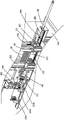
FIG. 1 is a schematic perspective view of a flexibly controlled butt-welding apparatus of one embodiment of the present invention;
FIG. 2 is a side view of the flexibly controlled butt-welding apparatus shown in FIG. 1;
FIG. 3 is a partial perspective view of the flexibly controlled butt-welding apparatus shown in FIG. 1;
FIG. 4 is a schematic perspective view of a main material feed mechanism of the flexibly controlled butt-welding apparatus shown in FIG. 1;
FIG. 5 is a front view of a main material feed mechanism of the flexibly controlled butt-welding apparatus shown in FIG. 1;
FIG. 6 is a front view of a stop mechanism of the flexibly controlled butt-welding apparatus shown in FIG. 1;
FIG. 7 is a schematic illustration of the main materials being welded by the flexibly controlled butt-welding apparatus of FIG. 1;
FIG. 8 is a cross-sectional view of a main material feeding mechanism of the flexibly controlled butt-welding apparatus shown in FIG. 1;
FIG. 9 is a schematic perspective view of an auxiliary material preparation mechanism of the flexibly controlled butt-welding apparatus shown in FIG. 1;
FIG. 10 is an enlarged partial view of the auxiliary material preparation mechanism of the flexibly controlled butt-welding apparatus shown in FIG. 1;
FIG. 11 is a schematic view of auxiliary materials welded by the flexibly controlled butt-welding apparatus of FIG. 1;
FIG. 12 is a schematic perspective view of an auxiliary material preparation mechanism of the other side of the flexibly controlled butt-welding apparatus of FIG. 1;
FIG. 13 is a perspective view of an auxiliary material feeding robot of the flexibly controlled butt-welding apparatus shown in FIG. 1;
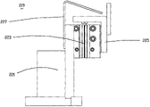
fig. 14, 15 are enlarged partial views of the flexibly controlled butt-welding apparatus shown in fig. 1.
Wherein the content of the first and second substances,
1. flexibly controlled butt-welding device 10, main body 20 and main material feeding mechanism equipment
30. Auxiliary material feeding manipulator 40, main material unloading mechanism 50 and auxiliary material preparing mechanism
70. Welding mechanism 80, main material 801 and first welding part
803. Second welding part 805, third welding part 90 and auxiliary materials
901. Short side 903, long side 101, base
103. Extension platform 105, extension cabinet 201, main material feeding cylinder
203. Main material preparing rack 209, main material feeding rod 211 and main material preparing side wall
213. Main material bracket 205, main material feeding piston rod 207 and feeding connecting piece
217. Major ingredient electrode 219, stop gear 215, major ingredient material loading guide rail
221. Limiting seat 223, limiting cylinder 225 and limiting part
227. Auxiliary electrode 501, auxiliary material preparing frame 503 and auxiliary material preparing frame
505. Auxiliary material bracket 507, hollow part 509 and supporting section
511. Conveying section 513, auxiliary material preparing cylinder 515 and auxiliary material preparing rod
517. Recess 519, guide 301, horizontal material cylinder
303. Horizontal material loading connecting piece 305, vertical material loading cylinder 307 and vertical material loading connecting piece
309. Vertical feeding cylinder 311, vertical feeding connecting piece 313 and feeding jaw
701. Welding working head 401, transverse blanking cylinder 403 and transverse blanking connecting piece
405. Vertical blanking cylinder 407, vertical blanking connecting piece 409 and blanking jaw
411. Blanking support
Detailed Description
The present invention will be described in detail below with reference to specific embodiments shown in the drawings of the specification. These embodiments are not intended to limit the present invention, and simple modifications made by those skilled in the art according to these embodiments are included in the scope of the present invention.
Fig. 1 to 15 show a flexibly controlled butt-welding apparatus 1 according to an embodiment of the present invention. The flexibly controlled butt-welding device 1 is used for welding together the main material 80 and the auxiliary material 90. Specifically, referring to fig. 1 and 2, the flexible control butt-welding device 1 includes a main body 10, a main material feeding mechanism 20, an auxiliary material feeding manipulator 30, a main material discharging mechanism 40, an auxiliary material preparing mechanism 50, a welding mechanism 70, and a flexible attaching mechanism a 1. Wherein, the main material feeding mechanism 20, the auxiliary material feeding manipulator 30, the main material discharging mechanism 40, the auxiliary material preparing mechanism 50 and the welding mechanism 70 are all arranged on the main body 10. The main body 10 includes a housing 101, an extension stage 103, and an extension cabinet 105. Wherein, the pedestal 101 is used for steadily placing on the ground, extends platform 103 and extends cabinet 105 fixed connection on pedestal 101, and extends platform 103 and is located the top that extends cabinet 105. The main material feed mechanism 20 is used to transport the main material 80 to the welding location. The auxiliary material preparation mechanism 50 is used to convey the auxiliary material 90 to a preparation position. The auxiliary material feeding robot 30 is configured to transfer the auxiliary material 90 at the material preparation position to the welding position. The welding mechanism 70 is used to weld the minor ingredients 90 to the major ingredients 80. The main material blanking mechanism 40 is used to convey the main material 80 away from the welding location. The flexible attaching mechanism A1 is used for eliminating the gap between the main material 80 and the welding mechanism 70, and the welding precision and quality are improved.
Referring to fig. 3 to 8, the main material feeding mechanism 20 includes a main material feeding cylinder 201, a main material preparing frame 203, and a main material feeding rod 209, which are fixedly disposed on the extension table 103. The main ingredient and ingredient holder 203 holds the main ingredient 80. Referring to fig. 7, in the present embodiment, the main material 80 is a longitudinally extending metal rod. The main stock shelf 203 includes two main stock sidewalls 211 and a main stock bracket 213 connecting the two main stock sidewalls 211. Two main material stock sidewalls 211 are spaced apart. The gap between the two main stock sidewalls 211 is used to contain the main stock 80. The gap between the major material stock sidewalls 211 is slightly greater than the width of the major material 80. The main material support bracket 213 supports the main material 80. The main materials 80 may be sequentially stacked on the main material tray 213. The main material feeding rod 209 is fixedly connected to the main material feeding piston rod 205 of the main material feeding cylinder 201, and is slidably disposed on the main material bracket 213. Further, the main material feeding mechanism 20 further includes a main material feeding guide rail 215 and a feeding rod connecting member 207. The loading rod attachment 207 is slidably disposed on the main material loading guide 215. The main material feeding piston rod 205 and the main material feeding rod 209 are fixed together by a feeding rod connecting piece 207. Specifically, the main material feeding piston rod 205 is fixedly connected to the feeding rod connecting part 207, and the feeding rod connecting part 207 is fixedly connected to the main material feeding rod 209. Further, the width of the main material loading bar 209 is also smaller than the gap between the sidewalls of the main material stock. The main material feed bar 209 may be driven by the main material stock cylinder 201 to slide along the gap between the side walls of the main material stock, thereby pushing the main material 80 on the main material carrier 213 to move to the welding position. The welding mechanism 70 includes a primary electrode 717. The primary material electrode 717 serves to support the primary material 80 in the welding position. The main material feeding mechanism 20 further includes a limiting mechanism 219. The limiting mechanism 219 and the main ingredient and spare material rack 203 are arranged on both sides of the welding position. The limiting mechanism 219 is located on an extension line of the moving direction of the main material 80 during the feeding process, and is used for stopping the main material 80 during the feeding process of the main material 80. Preferably, the number of the limiting mechanisms is multiple, and the limiting mechanisms are used for stopping the main material 80 in the main material feeding process, so that different parts of the main material 80 are located at the welding positions. Preferably, the number of the limiting mechanisms is three. Accordingly, referring to fig. 7, the main material 80 includes three welding locations. The first welding portion 801 and the third welding portion 805 are located at two ends of the main material 80, and the second welding portion 803 is located in the middle of the main material 80. The specific first limiting mechanism 219a is used for stopping the main material 80 for the first time in the loading process of the main material 80, so that the first welding position 801 of the main material 80 is located at the welding position; the second limiting mechanism 219b is used for stopping the main material 80 for the second time in the process of loading the main material 80, so that the second welding position 803 of the main material 80 is located at the welding position; the third limiting mechanism 219c is used for stopping the main material 80 for the third time in the loading process of the main material 80, so that the third welding position 805 of the main material 80 is located at the welding position. Referring to fig. 6, the limiting mechanism 219 includes a limiting seat 221 fixedly disposed on the extension stage 103, a limiting cylinder 223 fixedly disposed on the limiting seat 221, a limiting piston rod fixedly connected with the limiting cylinder 223 and a limiting member 225, and an auxiliary electrode 227 fixedly connected with the limiting seat 221. When the limiting piston rod of the limiting cylinder 223 extends out, the limiting member 225 extends out upwards and stops on the path of the main material 80 for feeding. So set up, can be so that the location of major ingredient is more accurate, improves welded precision. The auxiliary electrode 227 serves to support the main material 80 below the main material 80 after the main material 80 passes over the limiting mechanism 219. So set up the stability that can improve the major ingredient material loading in-process and welding process, promote the reliability of whole device.
Referring to fig. 3, 9, and 10, the auxiliary material preparing mechanism 50 includes an auxiliary material preparing frame 501, an auxiliary material preparing cylinder 513, and an auxiliary material preparing rod 515. The auxiliary material preparing frame 501 is used for storing auxiliary materials. The auxiliary material preparing frame 501 includes an auxiliary material preparing frame 503 and an auxiliary material bracket 505. The auxiliary material preparation frame is located above the auxiliary material carrier 505. The auxiliary material preparing frame 503 has a frame structure with a through-hole in the upper and lower surfaces and a hollowed-out portion 507 in the side surface. The auxiliary material preparing frame 503 is arranged above the auxiliary material bracket 505 in a surrounding manner to form a containing space for the auxiliary material 90. Referring to fig. 11, the auxiliary material 90 is a metal sheet having a substantially L-shaped side surface. That is, the auxiliary material 90 has an L-shaped side face 905, a short side portion 901 corresponding to a short side of the L-shaped side face, and a long side portion 903 corresponding to a long side of the L-shaped side face. Wherein the short side portion 901 and the long side portion 903 form an included angle of 90 °. The accessory carriage 505 comprises a support section 509 and a transport section 511. The support section 509 has a shape that fits the angle between the short side portion 901 and the long side portion 903 like a shape for supporting the auxiliary material 90 from the inside of the corner sandwiched by the short side portion 901 and the long side portion 903. And the support section 509 has a recessed slot 517. Auxiliary material preparation rod 515 may slide in recessed channel 517. The upper edge of the auxiliary material preparing rod 515 is higher than the lower surface of the lowermost one of the auxiliary materials 90 stacked on the auxiliary material holder 505 and lower than the upper surface of the auxiliary material 90. The hollowed-out portion 507 includes an edge that conforms to the shape of the auxiliary material 90. The hollowed-out portion is located on a side surface of the auxiliary material preparing frame 503 perpendicular to the auxiliary material preparing direction. More specifically, the edges of the hollow 507 are adapted to the upper surface of the lowermost one of the auxiliary materials 90 stacked on the auxiliary material holder 505 and slightly higher than the upper surface of the auxiliary material 90, so that the auxiliary material 90 and the auxiliary material preparing rod 515 can pass through the hollow. The edges of the hollow 507 are lower than the upper surface of the second auxiliary material 90 stacked on the auxiliary material bracket 505, so as to stop the auxiliary material 90, and prevent the auxiliary material 90 above the lowermost auxiliary material 90 from moving when being conveyed. Auxiliary material cylinder 513 and auxiliary material bracket 505 are fixedly connected, and the piston rod of auxiliary material cylinder 513 and auxiliary material preparing rod 515 are fixedly connected. When the piston rod of the auxiliary material cylinder 513 is extended, the auxiliary material preparing rod 515 can be pushed to slide in the concave groove 517 of the supporting section 509 of the auxiliary material bracket 505, so as to push the lowermost auxiliary material 90 stacked on the auxiliary material bracket 505 to the conveying section 511 of the auxiliary material bracket. After the supplementary material 90 enters the conveying section 511, the short side portion 901 is supported on the conveying section 511, and the long side portion 903 abuts against the side of the conveying section 511. The auxiliary material carrier 505 also includes guides 519. The guide member 519 is located on the side of the conveying section 511, and is used for guiding the long side portion 903 of the auxiliary material 90, so that the auxiliary material 90 is prevented from falling off the conveying section 511 in the conveying process, and a gap is formed between the guide member 519 and the conveying section 511, and the long side portion 903 of the auxiliary material 90 can pass through the gap. The conveying section 511 comprises a downwardly sloping surface and the auxiliary material 90 is turned over after entering the conveying section 511 until only the short edge portion 901 rests on the conveying section 511 and can be slid further along the conveying section to the stock preparation position. Referring to fig. 1-3 and 12, in a preferred embodiment, there are two auxiliary material preparation mechanisms 50, one on each side of the welding location. The structure and the working principle of the two auxiliary material preparation mechanisms are similar, the sizes of the prepared auxiliary materials are slightly different, so the shapes of the auxiliary material preparation mechanisms are slightly different according to the prepared auxiliary materials, and the detailed description is omitted here.
Referring to fig. 13, the auxiliary material feeding robot 30 includes a horizontal feeding cylinder 301, a horizontal feeding link 303, a vertical feeding cylinder 305, a vertical feeding link 307, a vertical feeding cylinder 309, a vertical feeding link 311, a feeding clamping cylinder (not shown), and a feeding jaw 313. Wherein the transverse feeding cylinder 301 and the extension table 103 are fixedly connected. The transverse feeding connecting piece 303 is fixedly connected to a piston rod of the transverse feeding cylinder 301. Further, the auxiliary material feeding manipulator 30 further includes an auxiliary material feeding guide 315 fixedly disposed on the extension table 103. The extending direction of the auxiliary material feeding guide rail 315 is consistent with the moving direction of the piston rod of the transverse feeding cylinder 301. The transverse feeding link 303 is slidably disposed on the accessory feeding rail 315. The longitudinal feeding cylinder 305 is fixedly connected with the transverse feeding connecting piece 303. The longitudinal feeding connecting piece 307 is fixedly connected to the piston rod of the longitudinal feeding cylinder 305. The vertical feeding cylinder 309 is fixedly connected with the longitudinal feeding connecting piece 307. The vertical feeding connecting piece 311 is fixedly connected to the piston rod of the vertical feeding cylinder 309. The feeding clamping cylinder is fixedly arranged on the vertical feeding connecting piece 311 and used for driving the feeding jaw 313 to clamp auxiliary materials. The moving directions of the transverse feeding cylinder 301, the longitudinal feeding cylinder 305 and the vertical feeding cylinder 309 are mutually perpendicular in pairs so that the feeding jaw 313 can freely move in the transverse direction, the longitudinal direction and the vertical direction. The transverse feeding cylinder 301, the longitudinal feeding cylinder 305, the vertical feeding cylinder 309 and the feeding clamping cylinder work together to convey the auxiliary material 90 located at the material preparation position to the welding position. In one embodiment, the minor ingredient 90 is stacked above the major ingredient 80 at the welding location. In a preferred embodiment of the present invention, there are two transverse feeding connectors 303, longitudinal feeding cylinders 305, longitudinal feeding connectors 307, vertical feeding cylinders 309, vertical feeding connectors 311, feeding clamping cylinders (not shown) and feeding jaws 313, respectively, for transferring two auxiliary materials 90 located at both sides of the welding position to the welding position.
Referring to fig. 1, 2, 14 and 15, the flexible attaching mechanism A1 includes an insulating body a101, a guide slide bar a102 movably connected to the insulating body a101, a moving connecting plate a104 fixedly connected to the end of the guide slide bar a102, a thrust spring a103 sleeved on the guide slide bar a102, and an insulating roller a105 movably connected to the moving connecting plate a 104; the insulating main body A101 is fixedly connected to a workbench 106 of the main body 10, and the thrust spring A103 attaches the insulating roller A105 to the side edge of the main material electrode 717; the top of the main material electrode 717 is provided with a wear-resistant electrode 718, and the wear-resistant electrode 718 is fixedly connected with the main material electrode 717 through a dovetail groove mechanism; a moving electrode 108 is provided on the upper portion of the main material electrode 717.
Referring to fig. 13, a welding mechanism 70 is fixedly provided on the main body 10. Specifically, the welding mechanism is hung on the base 101. The welding mechanism 70 includes a welding head 701, and when the main material 80 and the auxiliary material 90 are stacked with the welding position, the welding head 701 moves downward to a position above the welding position to weld the main material 80 and the auxiliary material 90 together.
Referring to fig. 4 and 5, the main material discharging mechanism 40 includes a discharging bracket 411 fixedly disposed on the extension table 103, a transverse discharging cylinder 401 fixedly disposed on the discharging bracket 411, a transverse discharging connector 403, a vertical discharging cylinder 405, a vertical discharging connector 407, a discharging clamping cylinder, and a discharging jaw 409. Wherein, the transverse blanking connecting piece 403 is fixedly connected with the piston rod of the transverse blanking cylinder 401. The vertical blanking air cylinder 405 is fixedly connected with the transverse blanking connecting piece 403. The vertical blanking connecting piece 407 is fixedly connected with a piston rod of the vertical blanking cylinder 407. The blanking clamping cylinder is arranged on the vertical blanking connecting piece and used for driving the blanking jaw to clamp the main material 80. The transverse blanking cylinder 401, the vertical blanking cylinder 405 and the blanking clamp cylinder cooperate to convey the main material 80 located at the welding location away from the welding location. It will be appreciated that the major and minor ingredients 80, 90 have now been welded together, so that the major and minor ingredients 80, 90 are conveyed together away from the welding location.
The operation and principle of the flexibly controlled butt-welding apparatus 1 will be described in detail with reference to fig. 1 to 13.
The piston rod 205 of the main material feeding cylinder 201 extends to push the feeding connecting piece 207 to slide along the main material feeding guide rail 215. The feeding connecting member 207 drives the main material feeding rod 209 to slide along the main material bracket 213, so as to push the lowermost main material 80 stacked on the main material bracket 213 to the first welding position 801 of the main material 80 to the welding position. At this time, one end of the main ingredient 80 is stopped by the first stopper 219 a.
In the auxiliary material preparing mechanism 50, the piston rod of the auxiliary material preparing cylinder 513 extends to push the auxiliary material preparing rod 515 to slide along the recessed groove 517 on the supporting section 509 of the auxiliary material bracket 505, so as to push the lowermost auxiliary material 90 stacked on the auxiliary material bracket 505 to the conveying section 511 of the preparation bracket 505. The auxiliary material 90 is turned over on the conveying section 511 until only the short edge portion 901 is supported above the conveying section 511 and continues to slide to the stock preparation position. And another auxiliary material preparation mechanism 50 also transports its auxiliary material 90 to its preparation location.
The auxiliary material feeding manipulator 30 moves the feeding jaw 313 to the material preparation position under the combined action of the horizontal feeding cylinder 301, the vertical feeding cylinder 305 and the vertical feeding cylinder 309. The feeding clamping cylinder causes the feeding jaw 313 to clamp the auxiliary material 90 located at the stock preparation position. The transverse feeding cylinder 301, the longitudinal feeding cylinder 305, the vertical feeding cylinder 309 and the feeding clamping cylinder work together to convey the auxiliary materials 90 to the welding position. Specifically, the auxiliary material feeding manipulator 30 conveys the auxiliary material located on the right side of the welding position to the welding position, and at this time, the auxiliary material 90 is stacked on the first welding position 801 of the main material 80.
Further, the welding head 701 of the welding mechanism 70 moves downward to the welding position, and the auxiliary material 90 is welded to the first welding portion 801 of the main material 80.
Then, the welding head 701 moves upward to be away from the welding position, and the main material feeding mechanism 20 further pushes the main material 80 to move in the feeding direction until the second welding position 803 of the main material 80 is located at the welding position. At this time, one end of the main ingredient 80 is stopped by the second stopper 219 b.
Then, the auxiliary material feeding manipulator 30 first conveys the auxiliary material located at the left side of the welding position to the welding position, and at this time, the auxiliary material 90 is stacked on the second welding portion 803 of the main material 80.
Further, the welding head 701 of the welding mechanism 70 moves downward to the welding position, and the auxiliary material 90 is welded to the second welding portion 803 of the main material 80.
Then, the welding head 701 moves upward to be away from the welding position, and the main material feeding mechanism 20 further pushes the main material 80 to move in the feeding direction until the third welding position 805 of the main material 80 is located at the welding position. At this time, one end of the main ingredient 80 is stopped by the third stopper 219 c.
Then, the auxiliary material feeding manipulator 30 first conveys the auxiliary material located at the right side of the welding position to the welding position, and at this time, the auxiliary material 90 is stacked onto the third welding portion 805 of the main material 80.
Further, the welding head 701 of the welding mechanism 70 moves down to the welding position, and the auxiliary material 90 is welded to the third welding portion 805 of the main material 80.
After the welding operation is completed, the horizontal blanking cylinder 401 and the vertical blanking cylinder 405 act together to transfer the blanking jaws to the two sides of the main material 80. Then, the feeding jaw 409 clamps the main material 80 by the feeding clamping cylinder. The transverse blanking cylinder 401, vertical blanking cylinder 405 and clamp cylinder then act together to transfer the main material 80 located at the welding location away from the welding location. It will be appreciated that the major and minor ingredients 80, 90 have now been welded together, so that the major and minor ingredients 80, 90 are conveyed together away from the welding location. Thus, the butt-welding equipment with flexible control completes the welding operation of the main material 80 and the auxiliary material 90.
The above-mentioned embodiments only express several embodiments of the present invention, and the description thereof is more specific and detailed, but not construed as limiting the scope of the present invention. It should be noted that, for a person skilled in the art, several variations and modifications can be made without departing from the inventive concept, which falls within the scope of the present invention. Therefore, the protection scope of the present invention should be subject to the claims.
Claims (10)
1. A flexible control butt-welding device is used for welding main materials and auxiliary materials together and is characterized by comprising a main body, and a main material feeding mechanism, an auxiliary material feeding manipulator, a main material discharging mechanism, an auxiliary material preparing mechanism, a welding mechanism and a flexible laminating mechanism which are arranged on the main body; the auxiliary material feeding mechanism is used for conveying the main material to a welding position, the auxiliary material preparing mechanism is used for conveying the auxiliary material to a material preparing position, the auxiliary material feeding manipulator is used for conveying the auxiliary material at the material preparing position to the welding position, the welding mechanism is used for welding the auxiliary material to the main material, the main material discharging mechanism is used for conveying the main material away from the welding position, and the flexible laminating mechanism is used for eliminating a gap between the main material and the welding mechanism and improving the welding precision and quality;
the main material feeding mechanism comprises a main material feeding cylinder, a main material standby material frame and a main material feeding rod, wherein the main material standby material frame comprises two main material standby material side walls and a main material bracket connected with the two main material standby material side walls, and the main material feeding rod is fixedly connected with a piston rod of the main material feeding cylinder and is slidably arranged on the main material bracket;
the auxiliary material preparing mechanism comprises an auxiliary material preparing frame, an auxiliary material preparing cylinder and an auxiliary material preparing rod, the auxiliary material preparing frame comprises an auxiliary material preparing frame and an auxiliary material bracket, the auxiliary material bracket comprises a supporting section and a conveying section, the supporting section is provided with a concave groove, the auxiliary material preparing rod can slide in the concave groove, and a piston rod of the auxiliary material preparing cylinder is fixedly connected with the auxiliary material preparing rod;
the auxiliary material feeding manipulator comprises a transverse feeding cylinder, a transverse feeding connecting piece, a longitudinal feeding cylinder, a longitudinal feeding connecting piece, a vertical feeding cylinder, a vertical feeding connecting piece, a feeding clamping cylinder and a feeding jaw, wherein the transverse feeding connecting piece is fixedly connected to a piston rod of the transverse feeding cylinder, and the longitudinal feeding cylinder is fixedly connected with the transverse feeding connecting piece;
the longitudinal feeding connecting piece is fixedly connected to a piston rod of the longitudinal feeding cylinder, the vertical feeding cylinder is fixedly connected with the longitudinal feeding connecting piece, the vertical feeding connecting piece is fixedly connected to the piston rod of the vertical feeding cylinder, and the feeding clamping cylinder is fixedly arranged on the vertical feeding connecting piece and used for driving the feeding jaw to clamp the auxiliary material;
the flexible attaching mechanism comprises an insulation main body, a guide sliding rod movably connected with the insulation main body, a motion connecting plate fixedly connected with the tail end of the guide sliding rod, a thrust spring sleeved on the guide sliding rod and an insulation roller movably connected with the motion connecting plate; the insulating main body is fixedly connected to a workbench of the main body, and the thrust spring enables the insulating roller to be attached to the side edge of the main material electrode; the top of the main material electrode is provided with a wear-resistant electrode which is fixedly connected with the main material electrode through a dovetail groove mechanism; the upper part of the main material electrode is provided with a moving electrode.
2. The flexible control butt-welding device according to claim 1, wherein the main material feeding mechanism further comprises a limiting mechanism, the limiting mechanism and the main material and auxiliary material rack are arranged on two sides of the welding position, and the limiting mechanism is located on an extension line of the motion direction when the main material is fed and used for stopping the main material during the main material feeding process.
3. A flexibly controlled butt-welding apparatus according to claim 2, wherein said plurality of limiting mechanisms are adapted to stop said main material during loading of said main material, thereby positioning a plurality of different portions of said main material at said welding location.
4. The flexible control butt-welding device according to claim 3, wherein the number of the limiting mechanisms is three, the main material comprises three welding positions, and the first limiting mechanism is used for enabling the first welding position of the main material to be located at the welding position; the second limiting mechanism is used for enabling a second welding part of the main material to be located at the welding position; and the third limiting mechanism is used for enabling a third welding part of the main material to be located at the welding position.
5. A flexibly controlled butt-welding device according to any one of claims 2 to 4, wherein the limiting mechanism comprises a limiting seat, a limiting cylinder fixedly arranged on the limiting seat, and a limiting member fixedly connected with a piston rod of the limiting cylinder, and when the piston rod of the limiting cylinder extends out, the limiting member extends upwards and stops on the path of the main material feeding.
6. The flexible control butt-welding device according to claim 1, wherein the auxiliary material preparation frame is substantially a frame structure with a through top surface and a through bottom surface and a hollowed-out portion on a side surface, and the auxiliary material preparation frame is arranged above the auxiliary material bracket in a surrounding manner to form an accommodating space of the auxiliary material.
7. A flexibly controlled butt-welding apparatus according to claim 6, wherein the upper edge of the auxiliary material preparation rod is higher than the lower surface of the lowermost one of the auxiliary materials stacked on the auxiliary material carrier and lower than the upper surface of the auxiliary material; the hollow part comprises an edge which is adaptive to the shape of the auxiliary material.
8. The flexibly controlled butt-welding equipment according to claim 7, wherein the hollow part is located on a side surface of the auxiliary material preparation frame perpendicular to the auxiliary material preparation direction, an edge of the hollow part is adapted to an upper surface of a lowermost auxiliary material stacked on the auxiliary material bracket and is slightly higher than the upper surface of the auxiliary material, and an edge of the hollow part is lower than an upper surface of a second auxiliary material stacked on the auxiliary material bracket.
9. A flexibly controlled butt-welding apparatus according to claim 1, wherein the auxiliary material preparation mechanism further comprises a guide located at a side of the transport section for guiding the auxiliary material.
10. The flexible control butt-welding device according to claim 1, wherein the welding mechanism comprises a welding working head, and after the main material and the auxiliary material are stacked at the welding position, the welding working head moves downwards to be above the welding position to weld the main material and the auxiliary material together; the main material blanking mechanism comprises a blanking support, a transverse blanking cylinder, a transverse blanking connecting piece, a vertical blanking cylinder, a vertical blanking connecting piece, a blanking clamping cylinder and a blanking jaw, wherein the transverse blanking cylinder, the transverse blanking connecting piece, the vertical blanking cylinder, the vertical blanking clamping cylinder and the blanking jaw are fixedly arranged on the blanking support, the transverse blanking connecting piece is fixedly connected with a piston rod of the transverse blanking cylinder, the vertical blanking cylinder is fixedly connected with a piston rod of the vertical blanking cylinder, and the blanking clamping cylinder is arranged on the vertical blanking connecting piece and used for driving the blanking jaw to clamp the main material.
Priority Applications (1)
| Application Number | Priority Date | Filing Date | Title |
|---|---|---|---|
| CN201810144832.9A CN108340061B (en) | 2018-01-30 | 2018-01-30 | Flexibly controlled butt-welding equipment |
Applications Claiming Priority (1)
| Application Number | Priority Date | Filing Date | Title |
|---|---|---|---|
| CN201810144832.9A CN108340061B (en) | 2018-01-30 | 2018-01-30 | Flexibly controlled butt-welding equipment |
Publications (2)
| Publication Number | Publication Date |
|---|---|
| CN108340061A CN108340061A (en) | 2018-07-31 |
| CN108340061B true CN108340061B (en) | 2020-06-02 |
Family
ID=62959337
Family Applications (1)
| Application Number | Title | Priority Date | Filing Date |
|---|---|---|---|
| CN201810144832.9A Active CN108340061B (en) | 2018-01-30 | 2018-01-30 | Flexibly controlled butt-welding equipment |
Country Status (1)
| Country | Link |
|---|---|
| CN (1) | CN108340061B (en) |
Family Cites Families (6)
| Publication number | Priority date | Publication date | Assignee | Title |
|---|---|---|---|---|
| JP2812894B2 (en) * | 1995-04-25 | 1998-10-22 | 本田技研工業株式会社 | Welding line system |
| CN203141491U (en) * | 2012-12-28 | 2013-08-21 | 西安沃恩机床有限公司 | Practical mechanical arm for micro-motor rotor machining |
| CN105171255B (en) * | 2015-09-02 | 2023-07-04 | 上海思客琦智能装备科技股份有限公司 | Door pocket welding robot system |
| CN204954460U (en) * | 2015-09-08 | 2016-01-13 | 上海北特科技股份有限公司 | Automatic loading and unloading device |
| CN206425707U (en) * | 2016-12-30 | 2017-08-22 | 永康市杰地希机器人科技有限公司 | The automatic processing apparatus and its control system of a kind of door frame |
| CN107552937B (en) * | 2017-08-31 | 2018-06-22 | 广东金客厨房科技有限公司 | A kind of multi-point quick welding device |
-
2018
- 2018-01-30 CN CN201810144832.9A patent/CN108340061B/en active Active
Also Published As
| Publication number | Publication date |
|---|---|
| CN108340061A (en) | 2018-07-31 |
Similar Documents
| Publication | Publication Date | Title |
|---|---|---|
| KR101749289B1 (en) | Machine tool | |
| KR20140132408A (en) | Board conveyance apparatus and board processing system using same | |
| US20080000072A1 (en) | Flexible Transfer Machine | |
| CN110744197A (en) | Welding equipment | |
| CN108340061B (en) | Flexibly controlled butt-welding equipment | |
| EP1927430A2 (en) | Turning unit | |
| EP1747845A1 (en) | Machining centre with chuck structure displacable in a horizontal and a vertical direction | |
| CN108890460B (en) | Double-side grinding processing equipment for crankshaft connecting rod | |
| CN107511555B (en) | Full-automatic electronic coil wicking machine | |
| CN114158206B (en) | Laminating machine | |
| CN112872662B (en) | U-shaped seat welding machine for frame beam of folding table | |
| CN214988232U (en) | Can carry PCB's transfer equipment fast | |
| CN112743513B (en) | Feeding and discharging equipment | |
| CN209834991U (en) | Feeding equipment | |
| CN112317870A (en) | Conveying device and sawing machine | |
| CN210653851U (en) | Tubular automatic packaging equipment for electronic components | |
| CN209777582U (en) | automatic loading attachment is arranged to heart | |
| EP1475204B1 (en) | Machine for processing wood panels or similar | |
| CN104527288B (en) | The production and processing system of the bed body of lathe and bed body with the lathe | |
| CN108857722B (en) | Crankshaft connecting rod double-side grinding machine | |
| CN108406174B (en) | Dual-arm robot cooperates with seamless welding to automate special purpose machine tool | |
| CN108406175B (en) | Automatic welding assembly line lathe | |
| JPS5976739A (en) | Automatic exchanger for tool of working machine | |
| CN108340101B (en) | The Automation of Welding equipment of curved surface non-percussion feeding | |
| CN110683330A (en) | Circulating tray feeder |
Legal Events
| Date | Code | Title | Description |
|---|---|---|---|
| PB01 | Publication | ||
| PB01 | Publication | ||
| SE01 | Entry into force of request for substantive examination | ||
| SE01 | Entry into force of request for substantive examination | ||
| GR01 | Patent grant | ||
| GR01 | Patent grant | ||
| TR01 | Transfer of patent right | ||
| TR01 | Transfer of patent right |
Effective date of registration: 20230517 Address after: 230000 Room 403, building 2, Laojie library, Dianbu Town, Feidong County, Hefei City, Anhui Province Patentee after: Hefei guiqian Information Technology Co.,Ltd. Address before: 325000 incubator of Wenzhou National University Science and Technology Park, 38 Dongfang South Road, Ouhai Economic Development Zone, Wenzhou City, Zhejiang Province Patentee before: WENZHOU VOCATIONAL & TECHNICAL College |