CN1082197C - Image forming apparatus having rotary developing device - Google Patents
Image forming apparatus having rotary developing device Download PDFInfo
- Publication number
- CN1082197C CN1082197C CN95105754A CN95105754A CN1082197C CN 1082197 C CN1082197 C CN 1082197C CN 95105754 A CN95105754 A CN 95105754A CN 95105754 A CN95105754 A CN 95105754A CN 1082197 C CN1082197 C CN 1082197C
- Authority
- CN
- China
- Prior art keywords
- toner
- box
- developing
- runner
- outlet
- Prior art date
- Legal status (The legal status is an assumption and is not a legal conclusion. Google has not performed a legal analysis and makes no representation as to the accuracy of the status listed.)
- Expired - Fee Related
Links
Images


Classifications
-
- G—PHYSICS
- G03—PHOTOGRAPHY; CINEMATOGRAPHY; ANALOGOUS TECHNIQUES USING WAVES OTHER THAN OPTICAL WAVES; ELECTROGRAPHY; HOLOGRAPHY
- G03G—ELECTROGRAPHY; ELECTROPHOTOGRAPHY; MAGNETOGRAPHY
- G03G15/00—Apparatus for electrographic processes using a charge pattern
- G03G15/06—Apparatus for electrographic processes using a charge pattern for developing
- G03G15/08—Apparatus for electrographic processes using a charge pattern for developing using a solid developer, e.g. powder developer
-
- G—PHYSICS
- G03—PHOTOGRAPHY; CINEMATOGRAPHY; ANALOGOUS TECHNIQUES USING WAVES OTHER THAN OPTICAL WAVES; ELECTROGRAPHY; HOLOGRAPHY
- G03G—ELECTROGRAPHY; ELECTROPHOTOGRAPHY; MAGNETOGRAPHY
- G03G15/00—Apparatus for electrographic processes using a charge pattern
- G03G15/01—Apparatus for electrographic processes using a charge pattern for producing multicoloured copies
- G03G15/0105—Details of unit
- G03G15/0126—Details of unit using a solid developer
-
- G—PHYSICS
- G03—PHOTOGRAPHY; CINEMATOGRAPHY; ANALOGOUS TECHNIQUES USING WAVES OTHER THAN OPTICAL WAVES; ELECTROGRAPHY; HOLOGRAPHY
- G03G—ELECTROGRAPHY; ELECTROPHOTOGRAPHY; MAGNETOGRAPHY
- G03G15/00—Apparatus for electrographic processes using a charge pattern
- G03G15/06—Apparatus for electrographic processes using a charge pattern for developing
- G03G15/08—Apparatus for electrographic processes using a charge pattern for developing using a solid developer, e.g. powder developer
- G03G15/0822—Arrangements for preparing, mixing, supplying or dispensing developer
- G03G15/0848—Arrangements for testing or measuring developer properties or quality, e.g. charge, size, flowability
- G03G15/0856—Detection or control means for the developer level
-
- G—PHYSICS
- G03—PHOTOGRAPHY; CINEMATOGRAPHY; ANALOGOUS TECHNIQUES USING WAVES OTHER THAN OPTICAL WAVES; ELECTROGRAPHY; HOLOGRAPHY
- G03G—ELECTROGRAPHY; ELECTROPHOTOGRAPHY; MAGNETOGRAPHY
- G03G15/00—Apparatus for electrographic processes using a charge pattern
- G03G15/06—Apparatus for electrographic processes using a charge pattern for developing
- G03G15/08—Apparatus for electrographic processes using a charge pattern for developing using a solid developer, e.g. powder developer
- G03G15/0822—Arrangements for preparing, mixing, supplying or dispensing developer
- G03G15/0865—Arrangements for supplying new developer
- G03G15/0867—Arrangements for supplying new developer cylindrical developer cartridges, e.g. toner bottles for the developer replenishing opening
- G03G15/087—Developer cartridges having a longitudinal rotational axis, around which at least one part is rotated when mounting or using the cartridge
- G03G15/0872—Developer cartridges having a longitudinal rotational axis, around which at least one part is rotated when mounting or using the cartridge the developer cartridges being generally horizontally mounted parallel to its longitudinal rotational axis
-
- G—PHYSICS
- G03—PHOTOGRAPHY; CINEMATOGRAPHY; ANALOGOUS TECHNIQUES USING WAVES OTHER THAN OPTICAL WAVES; ELECTROGRAPHY; HOLOGRAPHY
- G03G—ELECTROGRAPHY; ELECTROPHOTOGRAPHY; MAGNETOGRAPHY
- G03G15/00—Apparatus for electrographic processes using a charge pattern
- G03G15/06—Apparatus for electrographic processes using a charge pattern for developing
- G03G15/08—Apparatus for electrographic processes using a charge pattern for developing using a solid developer, e.g. powder developer
- G03G15/0822—Arrangements for preparing, mixing, supplying or dispensing developer
- G03G15/0887—Arrangements for conveying and conditioning developer in the developing unit, e.g. agitating, removing impurities or humidity
- G03G15/0891—Arrangements for conveying and conditioning developer in the developing unit, e.g. agitating, removing impurities or humidity for conveying or circulating developer, e.g. augers
- G03G15/0893—Arrangements for conveying and conditioning developer in the developing unit, e.g. agitating, removing impurities or humidity for conveying or circulating developer, e.g. augers in a closed loop within the sump of the developing device
-
- G—PHYSICS
- G03—PHOTOGRAPHY; CINEMATOGRAPHY; ANALOGOUS TECHNIQUES USING WAVES OTHER THAN OPTICAL WAVES; ELECTROGRAPHY; HOLOGRAPHY
- G03G—ELECTROGRAPHY; ELECTROPHOTOGRAPHY; MAGNETOGRAPHY
- G03G15/00—Apparatus for electrographic processes using a charge pattern
- G03G15/06—Apparatus for electrographic processes using a charge pattern for developing
- G03G15/08—Apparatus for electrographic processes using a charge pattern for developing using a solid developer, e.g. powder developer
- G03G15/0896—Arrangements or disposition of the complete developer unit or parts thereof not provided for by groups G03G15/08 - G03G15/0894
-
- G—PHYSICS
- G03—PHOTOGRAPHY; CINEMATOGRAPHY; ANALOGOUS TECHNIQUES USING WAVES OTHER THAN OPTICAL WAVES; ELECTROGRAPHY; HOLOGRAPHY
- G03G—ELECTROGRAPHY; ELECTROPHOTOGRAPHY; MAGNETOGRAPHY
- G03G2215/00—Apparatus for electrophotographic processes
- G03G2215/01—Apparatus for electrophotographic processes for producing multicoloured copies
- G03G2215/0167—Apparatus for electrophotographic processes for producing multicoloured copies single electrographic recording member
- G03G2215/0174—Apparatus for electrophotographic processes for producing multicoloured copies single electrographic recording member plural rotations of recording member to produce multicoloured copy
- G03G2215/0177—Rotating set of developing units
Landscapes
- Physics & Mathematics (AREA)
- General Physics & Mathematics (AREA)
- Color Electrophotography (AREA)
- Dry Development In Electrophotography (AREA)
- Control Or Security For Electrophotography (AREA)
Abstract
In an image forming apparatus, a rotary developing unit or revolver is loaded with a removable black developer container at the center thereof. The container is formed with a toner outlet. A receptacle assigned to black toner is provided at the end of the axis of the revolver and formed with a toner inlet. The receptacle constitutes a hopper portion. A supply roller is disposed in the receptacle. A screw conveyor extends out from a black developing chamber defined in the revolver into a communication chamber which communicates the receptacle to the developing chamber. A shutter is located at the loner inlet of the receptacle and rotatable due to its own weight while the revolver is in rotation.
Description
The present invention relates to a kind of duplicating, facsimile equipment, printing or similar imaging equipment more particularly, relate to a kind of imaging equipment that rotary developing device is arranged.
Example with a kind of imaging equipment of rotary developing device or so-called runner discloses in Jap.P. prospectus 62-251772 and 63-78170 and Japanese Utility Model prospectus 63-41164.Runner is by rotary developing device, and rotation toner memory storage and toner conveyance device are formed.Developing apparatus can rotate near form is the image carrier of photosensitive drums, and has a plurality of developments sections or chamber in developing apparatus inside.Storage device is positioned at an end of developing apparatus coaxially.A plurality of apothecas are limited on the storage device and are corresponding one by one with corresponding developing room, and each all stores the toner of particular color.By conveying device, one in each apotheca and a plurality of developing rooms is connected.
Developing room and apotheca are such associated, promptly when relevant developing room when it is positioned on the developing location facing to image carrier ground, conveying device is on the position in corresponding apotheca, on this position, toner is owing to the cause of himself weight accumulates in for example bottom of apotheca.Conveying device is suitable for filling again in the developing room from the new toner of apotheca, in this developing room, has or the developer or the toner of a component type, or the potpourri of two component type developer or toner and carrier.When apotheca is used the light toner, must fill toner again from the outside.In order to save time and the labour who fills again, apotheca preferably should make a kind of Delevoping cartridge on the developing apparatus or form of container of removably installing to.Then, the box with the light toner will be easy to replace with the new toner Cartridge that is full of new toner.Present disclosure specification 63-41164 had enlightened a plurality of toner Cartridges that are releasably attached on the developing apparatus for a long time in aforesaid day.
When box is releasably attached on the developing apparatus, the conveying device of stretching out from developing room towards box almost be empty be undesirable.Preferably, round conveying device the toner inlet portion is set.All having one on each inlet portion enters the mouth accordingly with the outlet of relevant box.Inlet portion is communicated with developing room separately.What this structure had prevented operator and conveying device contacts operator's hand and clothes because this conveying device can be made dirty.Box, inlet portion and developing room preferably should be connected, thereby when a developing room was positioned on the developing location, the toner that is stored in the relevant box flowed into inlet under the effect of himself weight, like this, conveying device is in having of inlet portion and newly arrives on the position of toner.
Yet, say that from disposing the enough big space that will guarantee to hold a plurality of boxes is impossible sometimes, therefore, it also is impossible that box and developing room are combined in a manner described.And, at developing room and directly and must to provide mutual relationship between the inlet portion filled again of toner be top-priority, that is to say between box and inlet portion, better relationship to be arranged.The toner in box more particularly, when developing room remains on the developing location, toner conveyance device is in have on the position in the inlet portion of toner, even also can not flow into inlet portion by it self weight.So,,, just toner can not be filled the chamber again in case the toner in the inlet portion has consumed when a developing room remains on developing location when realizing continuously image forming.
The problems referred to above are present in the developing apparatus that a single developing room and a single toner Cartridge are arranged equally, as long as it is a kind of words of rotary developing device.In addition, suppose that box is not positioned on the axis that stretches out from developing room one side, but be positioned at the radially inwardly or outside place of chamber, and toner directly supplies in box the chamber and do not have a middle conveying device.Even this scheme also has same problem, make toner supply to indoor this layout from box because could form when having only inlet when the outlet of box and chamber to be positioned at a predetermined angular range.
One end of box will be longer than the other end of taking mouth out of, and the structure of box can be such, promptly owing to the rotation of developing apparatus, the toner that is positioned on the end can be moved towards outlet.Yet, after the toner around the outlet has refilled full developing room, unless remaining toner can not infeed indoor developing apparatus rotation.
Even after direct or indirect pick-up unit determined that box has been used the light toner, toner often was retained in around the box outlet with coherent condition.Be drawn out developing apparatus if having the box that adheres to toner, around toner falls and pollutes from outlet.In addition, this is undesirable aspect effective use toner.
Because box differed from one another with the time of light toner, preferably should be to replace independently of one another therefore.Under these circumstances, although the box of dummy status (hereinafter being called near final state) can show on the operation panel of equipment that identification air-conditioning toner is difficult for the operator.For example, the operator must pull out box and their weight of insentience one by one.
The installation portion that is used for mounting box is included in web, just be included on self developing room or with part that the chamber is connected on.Mutual relationship between the outlet of the inlet that forms on the installation portion and box on upper and lower direction along with the angle position of runner just the box position variation and change.Therefore, when box can be replaced independently of one another and one of them box is drawn out, on the angle position above chamber inlet is arranged on the box outlet, when chamber inlet has toner, in inlet and around inlet toner on every side falls into and makes dirty.
In addition, suppose that the shape of box outlet is easy to make toner to accumulate in around it, so, if pull out box on the angle position above the box outlet is positioned at chamber inlet, toner also can fall from the box exit.
Therefore, an object of the present invention is to provide a kind of imaging equipment that a runner is arranged, it has been avoided when toner is still in a toner Cartridge, only, developing apparatus allow when deciding angular range toner to supply to chamber inlet from the box outlet when being positioned to give, and will be transported to the other end of outlet from the toner of box one end the time, toner can not be filled the defective of developing room again.
Another object of the present invention provides a kind of imaging equipment with a runner, and it helps convenient and replaces toner Cartridge effectively.
A kind of imaging equipment of the present invention has one in abutting connection with rotary developing device image carrier, that have at least one to be with the development section of toner inlet, and a storage will reload the interior toner of the section of developing and dismountable toner Cartridge that toner outlet is arranged.A drive source makes the developing apparatus rotation.When image forming repeated more than pre-determined number, controller interrupted image forming and drive source is arranged on developing apparatus in the predetermined rotational angle range.Have only when developing apparatus is positioned at predetermined angular range, through toner outlet and toner inlet, toner is filled the part of developing section or being connected with the section of developing again from toner Cartridge.
Similarly, a kind of imaging equipment of the present invention have one in abutting connection with image carrier, have the rotary developing device that at least one has the development section of toner inlet, and storage will be filled the toner of the section of developing again and the removable cartridges of toner outlet is arranged.A drive source makes the developing apparatus rotation.When image forming repeated more than pre-determined number, controller interrupted image forming and drive source is arranged on developing apparatus in the predetermined rotational angle range.The shape of toner Cartridge is such, and promptly because the rotation of developing apparatus, the toner on the opposite end of the end with the toner outlet is arranged of contiguous toner Cartridge is carried towards the toner outlet.
In addition, a kind of imaging equipment of the present invention has a plurality of development sections.Each of a plurality of toner Cartridges all stores the toner that will add to again in one of them section of developing, and has a toner outlet.Each of a plurality of installation portions all with develop one of section or be connected with appropriate section that one of the section of developing is communicated with, and all have the toner inlet of reception from the toner of one of toner Cartridge that is removably mounted on this part.A clamper clamping toner Cartridge, thus they can become whole moving with installation portion in equipment.A drive source drives clamper, and toner Cartridge is moved in equipment.Each of a plurality of sensors determines directly or indirectly that all toner is whether in toner Cartridge separately.Controller makes drive source work one preset time according to the output of arbitrary sensor.
Moreover a kind of imaging equipment of the present invention has a plurality of development sections.Each of a plurality of toner Cartridges all stores the toner that will add to again in one of them section of developing, and all has toner outlet separately.Each all is connected a plurality of installation portions with the appropriate section of developing one of section or be connected with one of the section of developing, and all has the toner inlet of reception from the toner of one of toner Cartridge that is removably mounted on this part.A clamper clamping toner Cartridge, thus they can become integrally to move with installation portion in equipment.A drive source drives clamper, and toner Cartridge is moved in equipment.Each of a plurality of sensors determines directly or indirectly that all toner is whether in toner Cartridge separately.According to the output of arbitrary sensor and only when equipment satisfies predetermined condition, controller just makes drive source move to predetermined replacement position with the toner Cartridge of light toner with arbitrary.When equipment satisfies predetermined condition and suppose that corresponding sensing has been determined a plurality of toner Cartridges and used the light toner, controller will move with the light toner and a toner Cartridge that be the most close predetermined replacement position on the toner Cartridge movable passageway earlier in a predetermined direction.
Above and other objects of the present invention, characteristics and advantage will become more apparent in the detailed description in conjunction with the accompanying drawings below, wherein
Fig. 1 is the partial elevation view that embodies imaging equipment of the present invention, and the example of this equipment is an electrophotographic printer;
Fig. 2 is the outward appearance skeleton view that comprises the parts decomposition of runner in an embodiment;
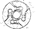
Fig. 3 is the plan view of runner;
Fig. 4 is the local skeleton view that amplifies of runner;
Fig. 5 is the cut-open view along X-X line among Fig. 3;
Fig. 6 is illustrated in the development section in the runner and the sectional view of a connectivity structure between the toner canned paragraphs;
Fig. 7 A is the perspective elevation of drive path in the expression runner;
Fig. 7 B is expression applies the device of bias voltage to runner figure;
Fig. 7 C is the sectional view of the another kind of runner of expression;
Fig. 8 A is the sectional view that is illustrated in the drive motor in the runner;
Fig. 8 B is the front elevation of motor section face;
Fig. 9 is the cut-open view along Y-Y line among Fig. 3;
Figure 10 is color toner (container) box in runner and the skeleton view of mounting portion thereof;
Figure 11 A is that the explanation box is the figure that how to install on the mounting portion;
Figure 11 B is the figure of expression to the box sensor sensitive;
Figure 12 A is the side view of the black toner box in runner;
Figure 12 B is the front elevation of black toner box;
The figure of the state that toner was occurred when Figure 13 A-13D was the rotation of expression runner;
Figure 14 A is a block scheme of schematically representing to be contained in the control system in the printing machine;
Figure 14 B is the plan view of another kind of console panel in the expression control system;
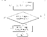
Figure 15 is the process flow diagram of explanation control system concrete operations;
Each all is figure of the other concrete operations of expression control system for Figure 16 A and Figure 16 B;
Each all is figure that expression control toner refills full specific procedure of being rotated for Figure 17 A-17C;
Figure 18 A and 18B are the figure of the state of color toner in the continuous polychrome copy mode of expression; And
Figure 19 A-19E is the figure of expression rotary course of runner when moving into color toner in the box.
Referring to Fig. 1, its expression embodies a kind of imaging equipment of the present invention and as a kind of example of electrofax chromatic printing machine.As shown in the figure, printing machine has photosensitive drums or image carrier 1, and it is by the rotation of the diagram direction of arrow.Main charger 2 charges the surface of drum 1 equably.Laser 3 also forms latent image thereon statically according to the charging surface of pictorial data scanning drum 1.Pictorial data comprises separates the yellow data that produced, peony data, cyan data and black data with desirable full-colour image.Each latent image that order forms on drum 1 is developed by each color that is stored in one of the rotary developing device that will illustrate or yellow, peony, cyan and the black toner in the runner 4.The result is that latent image is converted into the toner image of each color.
One intermediate transfer belt 5 synchronously turns round with drum 1 on direction B.The toner image that forms on drum 1 is positioned at sequentially to be transferred on another by 6 one of elementary transfer printing chargers to be with on 5, thereby forms compound color image.By means of a pick-up roller 8 or 8a and pair of registration rollers 9, the paper 10 that will come from two a duplicating/automatic paper feed cassette 7 or manual paper supply dish 7a is transported to the image conversion position.Be arranged on the locational second transfer printing hopper loader 11 of image conversion with the composite coloured image conversion on 5 to paper 10.Fixing device 12 with the color image photographic fixing to paper 10.The paper 10 that is printed on color image is discharged from printing machine as panchromatic folder.One tubular remover 3 behind the image conversion is being removed the toner of staying on the drum 1.Similarly, the toner of tape erasure device 14 on will staying with 5 behind the image conversion disposed.
Referring to Fig. 2, runner 4 has one and is roughly a columniform developing apparatus 40 and a toner storage device 45.Developing apparatus 40 can have around the rotation of himself axis and it to be respectively applied for as black, cyan, yellow and wine-colored 4 and develops section.Toner storage device 45 and developing apparatus 40 coaxial settings and be positioned at the front portion of developing apparatus 40,4 toner Cartridges 41,42,43 and 44 removably install in the storage device 45 and with 4 section clampings correspondingly of developing of developing apparatus 40.Toner Cartridge 41-44 stores black, yellow, peony and cyan toner respectively.Storage device 45 becomes rotatable integral body with developing apparatus 40.Shell 46 is supporting developing apparatus and storage device 45 runner just, and shell 46 can slide being roughly parallel on the axis of runner relatively the printing machine main body.Can not cover storage device 45 by revolvable lid 47.
For example, two backing rolls 49 are contained on the preceding support plate 48 of shell 46.Developing apparatus 40 has an antetheca 50 and a rear wall 51, and each all has the dish type profile.Antetheca 50 is by backing roll 49 supporting, and conical centre's axle 52 stretches out from the center of rear wall 51 and rotatably is placed to the hole 54 on the plate 53 of back, and back plate 53 is the part of printing machine main body.In this case, to be rotatable and such its axis of positioning instant in the printing machine main body parallel with the axis of the drum 1 in same plane basically runner, sees Fig. 1.
Shell 46 also has back support plate 55 and side cover 59 except preceding support plate 48.The two ends of side cover 59 are fixed on support plate 48 and 55 and by bar 56,57 and 58 to be strengthened.Have through hole 60 on support plate 48, it is used to hold runner.Motor 61 and gear train 62 (see figure 3)s also are contained on the support plate 48.Motor 61 drives the toner supplying roller that is arranged in the toner storage device 45 through gear train 62.See Fig. 4, intermediate plate 63 is arranged in the shell 46 and by being positioned near back support plate 55 bars 56 and 57 and is supporting.One register pin 63b links to each other with plate 63 and is installed among the pilot hole 63a of back on the plate 53.One end of carriage 64 rotatably is installed to pin 63b and inserts on the part between plate 63 and the back support plate 55.Registration roller 66 is contained on the other end of carriage 64.Roller 66 falls within a plurality of grooves 65 (being 4 in the present embodiment) that form on the aft bulkhead periphery of developing apparatus 40 in arbitrary groove.Spring 67 direction shown in the arrow consistently bias voltage carriage 64.As a result, when one of groove 65 and during pair roller 66, roller 66 must fall in the groove 65, specifically referring to Fig. 7 A and 7B.How to utilize groove 65, roller 66 and other member make will explaining below of runner location.
Have opening 69 on the header board 68 in the printing machine main body, it is used to hold the shell 46 that carries runner.Last guiding element 70 and following guiding element 71 are in the header board 68 of printing machine main body and extension between the plate 53 afterwards.Shell 46 is being supported slidably by guiding element 70 and 71.Particularly, the side cover 59 of shell 46 has respectively at top and the sidepiece parts 72 and 73 by guiding element 70 and 71 guiding.Form guide groove 75 in the bottom of parts 73 and link upright pilot pin 74 on the guiding element 71 with reception.When shell 46 moved into the printing machine main body and therefrom shifts out, guide groove 75 was away from drum 1.Similarly, when shell 46 was positioned on the printing machine main body fully, guide groove 75 imported the precalculated position nearer with drum 1 with runner.For this reason, guide groove 75 is by crooked like this, and promptly its predetermined front portion is than the more close drum 1 in rear portion.
The register pin of linking on the intermediate plate 63 has taper top.Just before shell 46 is put into the printing machine main body fully, begin to make the taper jacking to go among the hole 63a of back plate 53 and when shell 46 is laid fully, the back support plate 55 of shell 46 is located exactly.The preceding support plate 48 of shell 46 in shell 46 has been inserted into the printing machine main body after, by means of as bolt 76, and be fixed together with printing machine header board 68.In the time of in shell 46 is not inserted into the printing machine main body, the rear end of runner is being supported by the back support plate 55 of shell 46.Yet just before shell 46 is put into the printing machine main body fully, conical centre's axle 52 begins to enter in the hole 54 of plate 53 behind the printing machine, then promotes runner.In the time of in shell 46 is inserted into the printing machine main body fully, runner raises fully, leaves support plate 55.In this case, the front end of runner is being supported by the roller 49 on the preceding support plate 48 that is positioned at exactly on the printing machine main body.Simultaneously, plate 53 is rotatably being placed behind the relative printing machine in the rear end of runner.
See Fig. 3, the motor 77 that drives runner is contained in behind the printing machine on the plate 53, is a stepper motor in this example.An output gear 78 also is contained in behind the printing machine and drives on the plate 53 and by motor 77.Output gear 78 is being fixed with input gear 79 with being meshed.The diameter of input gear 79 and the diameter of output gear 78 are basic identical.Input gear 79 is fixed to the rear portion of developing apparatus 40 aft bulkheads.Equally, one is used to drive the gear case 82 that output gear 81 and that developer roll and other motor 80, one that is contained in the rotary body in the developing apparatus 40 drive by motor 80 holds the gear train 62 that motor is linked to each other with corresponding output gear and all is installed on the back plate 53 of printing machine.
Fig. 5 is that it shows the internal configurations of developing apparatus 40 along the cut-open view of X-X line among Fig. 3.As shown in the figure, developing apparatus 40 (see figure 3) except the forward and backward end wall of plate-like also has the partition that is inserted between preceding and the rear wall.Partition is by hollow cylinder portion 82 and 4 cover portions 83 of receiving cylindrical black toner bottle, 83C, and 83M and 83Y form.The 83-83Y of cover portion radially extends and will become 4 developing rooms around its space interval from cylindrical portion 82, and these developing rooms have roughly the same shape.The mixture that each of these chambers all stores the toner of absorbing agent and particular color is the developer of twenty percent somatotype.Under situation shown in Figure 5, the chamber of storage black toner shown in the figure and absorbing agent is in developing location and faces toward drum 1.Store Yellow toner and absorbing agent respectively, is arranging the chamber of peony toner and absorbing agent and cyan toner and absorbing agent in turn in a clockwise direction order, as shown.
To be illustrated the black developing room that is positioned on the developing location emphatically below, other developing room is used prefix Y mutually for being different from the black developing room, and M and C represent.
In the black developing room, cover portion 83 forms an opening in the face of drum 1.Being positioned at indoor developer roll 84 parts reveals outside the opening.Indoor a guiding element 87 and the impeller 88 that spiral 86, on the scraping blade 85, is used for spiral 86 be set also.Scraping blade 85 is regulated the toning dosage that roller rest 84 is transported on the developing location.Last spiral 86 is carried by scraping blade 85 along it around the part developer of being removed from back to front.Particularly, impeller 88 has a hollow cylinder portion 89 and a plurality of cylindrical portion 89 is formed with a plurality of developer outlet 89a along the radially extended blade 90 of cylindrical portion 89, and these outlets 89a is in the axial stretching, extension of roller 84.Following spiral 91 be arranged in the cylindrical portion 89 and along it axis with spiral 86 reverse direction supplying developing agent.Cover portion is forming outlet 92 under the spiral 91 down.Outlet 92 extending axially and being used for discharging rotten developer selectively or filling new developer (band toner) again at runner.Cap 93 installs to cover portion to close outlet 92 by means of for example bolt 94.
In order to discharge rotten developer 92 effectively from exporting, preferably from the printing machine main body, release and shell 46 runner together, with anchor clamps rotation input gear 95 (seeing Fig. 7 A) and other gear, then, at developer roll 84, spiral 86 and 91 and impeller 88 discharging developer when rotating.Similarly, in order to send into new developer, preferably should make roller 84, spiral 86 and 91 and wheel rotation, to sow developer equably through exporting 92.
Fig. 6 comprises the longitudinal sectional drawing that spiral 86 and lower shaft revolve the plane of 91 axis.As shown in the figure, spiral 86 and 91 front end extend to that the effective width of developer roll 84 is outer (to extend to the outside of the end wall 50 of developing apparatus 40 in the illustrated embodiment.) form drippage section 96 round the extension of spiral 86 and 91.In drippage section 96, the developer of being carried by spiral 86 drops on the spiral 91 in action of gravity.The front end of spiral 91 further stretches out drippage section 96, arrives the communication chamber that is positioned at toner supplying roller 97 belows, and toner supplying roller 97 is in toner storage device 45, and these will be illustrated in the back specially.In this structure, the developer part that is deposited on the roller 84 is removed by scraping blade 85, is transported to the front portion by guiding element 87 and spiral 86 then.In drippage section 96, this part developer is fallen on the spiral 91.Spiral 91 is transported to developer on the effective width of roller 84.As a result, developer is discharged into indoor and deposits to once more on the roller 84 from impeller 88 through outlet 89a.By this way, developer stirs in the indoor horizontal direction.The developer that is discharged into the bottom, chamber through outlet 89a passes through the blade 90 of impeller 88 in vertical stirring.Simultaneously, toner supplying roller 97 rotations are to fall new toner on the spiral 91 in the communication chamber.Spiral 91 is transported to drippage section 96 with new toner.In case arrive drippage section 96, toner just mixes mutually with the developer that is dripped by spiral 86.Final potpourri in outlet 89a inlet chamber, thereby increase the concentration of indoor toner.
Fig. 7 A is the skeleton view of developing apparatus 40 aft bulkheads 51.As shown in the figure, various gears are contained on the wall 51 that is positioned at runner input gear 79 rear portions.The axle of developer roll 84 passes the rear portion that wall 51 extends input gear 79.Gear 98 be contained in roller 84 the axle external part on.Similar ground, spiral 86 and 91 axle pass the rear portion that wall 51 extends input gear 79.Gear 99 and 100 is contained in respectively on the external part of spiral 86 and 91.Idle pulley 101 is contained in the rear portion of wall 51 and keeps engagement with gear 98 and 100.The input gear 95 also be contained in wall 51 the rear portion and with output gear 81 be engageable.Carry such runner that is contained in the gear on the wall 51 and be placed in and be inserted into then in the shell 46 in the printing machine main body, as discussed previously.As a result, input gear 95 beginnings of runner and output gear 81 engagements of printing machine main body are shown in Fig. 7 A.Simultaneously, the input gear 79 of runner meshes with the output gear 78 of printing machine main body.
Fig. 8 A and 8B are respectively the plan view and the front elevations of expression runner drive motor part.As shown in the figure, the gear 78 of printing machine main body and 81 can be in the glide direction indentation of shell 46, so in shell 46 is inserted into the printing machine main body time, the gear of printing machine main body can mesh exactly with the gear of runner.Gear 78 and 81 is pressed to the printing machine main body unvaryingly by spring 102 and 103 respectively.Therefore, though in shell 46 insertion process the gear 789 of printing machine main body and 81 and the gear 79 and 95 of runner influence each other, but gear 78 and 81 also indentation to guarantee insertion work.Then, because the rotation of gear 78 and 81, interference is disengaged.Under spring 102 and 103 effects, gear 78 and 81 is pushed out into the most close runner place, thereby meshes fully with gear 79 and 95.
Fig. 7 A illustrates a kind of situation, and promptly said gear is in the state of engagement fully mutually.In this case, output gear 81 is in the rotation of A direction, and the result is that gear 99 and 100 rotates by input gear 95.Gear 99 and 100 makes spiral 86 and 91 rotations.In addition, gear 98 is by input gear 95, and gear 100 and idle pulley 101 rotate, and it makes developer roll 84 rotations again.
In the illustrated embodiment, in order to replace development section at developing location, make output gear 79 by the B of Fig. 7 A to rotation, thereby at C to rotating wheel.Then, roller 66 drops in the groove 65 that forms on runner aft bulkhead 51 outer peripheral edges.Suppose because the erratic behavior runner of the irregular and runner load of motor 77 fails to rotate a required angle (be 90 ° for example, this moment, another section was just in the former upstream) when the development section that will be arranged on developing location is replaced.At this moment, roller 66 fails to match with desired groove 65, just fails to make the runner location.As a result, the distance between developer roll 84 and the drum 1 is different from and gives set a distance.For fear of the problems referred to above, illustrated embodiment has following scheme.
Consider above-mentioned erratic behavior, among the embodiment by using one to control the rotation of motor 77 with a little slightly greatly angle (for example about 3 °) controlling value that adapts of required angle, thereby guarantee the rotation of required angle.Even when making the runner rotation surpass required angle owing to this controlling value, when motor 80 began to rotate, on the basis of torque at runner, runner still can be located exactly.Especially shown in Fig. 7 A, be arranged in developing location on the development section on the output gear 81 that is meshed of input gear 95 by A to rotation (as at common developing process).As a result, torque affacts on the runner on the direction opposite with the direction (outlined arrow D) of the common rotation of runner, thereby runner is returned.Simultaneously, roller 66 1 falls in the particular groove 65, and runner just stops revolution, and is on the throne thereby runner is fixed.For this reason, the position of the pin 63 of frame support bracket 64 and the position of selling 63 relative runners are determined that so promptly carriage 64 is offset the rotation of runner on gyratory directions.In addition, when because above-mentioned controlling value, runner rotates when surpassing required angle, and roller 66 falls in the groove 65 and breaks away from it then.At this in an instant, preferably reduce the load that acts on the drive path.For this reason, shown in Fig. 7 B, each groove 65 can be made up of two parts 65a and 65b; Part 65p has the inclination angle littler than part 65a.In common turning course, roller 66 is easy to break away from groove 65 by part 65a.Another part 65b is used for pinning runner.
As shown in Figure 5, the scraping blade 85Y that for example yellow developing apparatus has developer roll 84Y and supported by preceding and back little wall piece 104, little wall piece 104 can separate with other preceding and rear wall parts.When wanting the purge chamber or replacing parts, the little wall piece 104 that carries roller 84Y and scraping blade 85Y can be beneficial to lead to the chamber by whole removing.
Shown in Fig. 7 C, when axle 98a entered developing location, on the position facing to development roll shaft 98a, carriage 107 installed to behind the printing machine on the plate 53.One shaft-like cover 106 is being supported by this way by carriage 107, and promptly it is telescopic on the glide direction of shell 46.Spring 107a will overlap 106 unvaryingly and press forward.Cover 106 has a dome.The end of developer roll 84 forms the hemisphere top bigger groove of a diameter than cover 106, and this groove has an arc-shaped sections.When the end of axle 98a in the runner rotary course, enter cover 106 or with cover during 106 misalignment, make the end of a 98a and overlap 106 top and the effect minimum contact load on it to engage and be disengaged, and make their keep stable to contact.
Fig. 9 is that it illustrates the internal configurations of toner storage device 45 along the cut-open view of Y-Y line among Fig. 3.This cut-open view has represented that equally black developing device is positioned at the situation of developing location.As shown in the figure, storage device 45 has a discoid substrate 108 (equally referring to Fig. 2).4 containers or box 109Y, 109M, 109C and 110 is fixed to the front end of substrate 108, and each is all corresponding to a chamber of developing apparatus 40. Toner supplying roller 97Y, 97M, 97C and 97 is separately positioned on container 109Y, and 109M is among the 109C and 110.Roller 97Y-97 pivotally links on the antetheca of substrate 108 and relevant container 109Y-110, thereby when respective compartments enters developing location, every-individual top that just be positioned at spiral 91 extensions basically of inciting somebody to action of roller 97Y-97.
There is a manhole 111 at the center of substrate 108.Hole 111 allows cylindrical black toner box (seeing Figure 12 A and 12B) to pass.Container 109Y-110 is so positioned, and promptly it does not hinder the hole of the following spiral 91 that is used for stretching out outside developing room, and does not hinder the hole that is used for groove shape screw top 112 (see figure 10)s, and lid 112 is annexes.Each conveyor screw 91 extend among one of container 109Y-110 through substrate 108.
Figure 10 shows the container 109C and the cyan toner box 44 of the cyan toner that is used to stipulate.Container 109Y, 109M and 109C are of similar shape.For example container 109C has a wall round following spiral 91 parts in container 109C.Form toner outlet on the wall, it is in such position, and promptly when the chamber of regulation was positioned on the developing location, outlet was positioned at above the toner supplying roller 97C.Outlet is surrounded by mounting portion 113.44 outlets of cyan toner box are installed to downwards on the installation portion 113, can slide along the axis direction of runner.Seal 114C installs in the face of on the inner peripheral of the container 109C of the roller 97C part.Seal 114C and roller 97C are divided into respectively two parts in abutting connection with toner Cartridge 44 and chamber with installation portion 113 inside.In addition, the wall around seal 114C and roller 97C and the spiral 91C defines the communication chamber of previous narration, and the hole of communication chamber on substrate and drippage section are connected with relevant developing room.
Referring to Figure 10 and 11A, installation portion 113 has such shape, promptly by runner shaft to slip, relevant color toner box can be installed or pull down, safety member 11 (seeing Figure 11 A) is positioned on the installation portion 113 and stretches into toner Cartridge through the toner outlet.Real in the opposite direction promptly when author's direction is slided when toner Cartridge, safety member 115 prevents that toner Cartridge from pulling out.Slit 116 is formed in the export department of painting box.For toner Cartridge is taken off for 113 times from installation portion, lock spare 117 is inserted in the slit so that safety member 115 is shifted onto outside the toner Cartridge, when new color toner box installs on the installation portion 113 under its sealed of toner outlet is closed, preferably on installation portion 113, slide it, take off seal then to expose the toner outlet.
In the process of replacing the color toner box, lid 47 (Fig. 2) serve as a member that is used for adjusting position, and this position is for replacing or reply the position.Referring to Fig. 2, cover 47 downstreams that are positioned at respect to box pull-out direction from canned paragraphs 45 especially.Lid 47 has a moving part 47a, only allows box to pull out from the 47a of this.The moving part 47a part that forms on end wall is made up of three adjacent portions, promptly one is used for along the central part of the black toner box of runner axis setting, one is used for the notch 130 (will be illustrated) of the lug 128 on the black toner box, an and circumference that is used for single color toner box, in this embodiment, when arbitrary development section is positioned on the developing location, aim at above-mentioned circumference corresponding to this color toner box that develops section.Therefore, represent that prepare when circumference is pulled out at box on the installation portion 113, the inlet face of installation portion 113 placing up as Fig. 9.In this case, even when toner is near installation portion 113 inlet when box is pulled out, also can prevent the phenomenon of toner around inlet scatters.
Suppose when toner Cartridge is drawn out, not use the lock spare 117 among Figure 11 A, or hypothesis is because the specific a large amount of toners of shape are easy to accumulate in around the color toner box and part toner steering brake spare 117 outsides.So, probably, the toner that the toner that falls into the prone box outlet during from replacement leaks than 113 porch from the mounting portion is many.Under so a kind of situation, preferably form the circumference that the color toner box is used in this wise, promptly it aligns with the supine color toner box of outlet (the peony toner Cartridge among Fig. 9).
No matter be color toner or black toner, all be easy to stick near the box outlet.Have the box that adheres to toner if pull out, toner be easy to the drippage and make dirty around.In view of the above, among this embodiment before replacing it loose toner and loose toner is sent in the toner receiving hood.In addition, when the end, the rotation of control runner among the embodiment is replaced the position thereby the box that will replace automatically moves on at toner, and these are with explanation specially below.
See Fig. 9, the container 110 that is used for the black chamber have one with color toner container 109Y, 109M or 109C and dress color toner box 42,43 thereon or 44 the essentially identical wall of profile, seal 114 are contained on the part inner peripheral of container 110 of corresponding container.Similarly, the common communication chamber that is connected with relevant developing room that limits of the wall around seal 114 and the spiral 91.The wall portion that is similar to the color toner box is entering the mouth 122 in the face of forming toner on the part of runner center line.It is identical that the shape of toner inlet 122 and toner on the box 41 shown in Figure 12 A and the 12B export 121 shape.The black toner that receives from box 41 is being similar to the wall portion of color toner box and is filling up on the corresponding part of hopper in the device by roller 97 and adjacent part and with conventional toner again through 122 productive sets that enter the mouth.Black toner is sent to communication chamber from these parts under roller 97 effects.One end of lock spare 124 is rotatably mounted by the axle 123 that is parallel to the runner axis.Inlet 122 can be barred up by lock spare 124 in the inside of container 110.Particularly, lock spare 124 since the weight of himself it can move round axle 123 angledly when runner turn round, enter the mouth 122 thereby automatically open and close.Seal 125 is contained in the limit portion of lock spare 124.
Figure 13 A-13D has illustrated at runner along diagram direction of arrow when rotation, how the toner in each toner Cartridge 41-44 and black toner container 110 moves.Because it is identical moving color toner box 42-44 with regard to toner, so only be illustrated in the toner in the Yellow toner box 42.With regard to black toner, when the black chamber is positioned on the developing location, the toner in container 110 since himself weight under the guiding of container 110 walls, move down, as shown in FIG. 13A.Black toner accumulate in be positioned at toner supplying roller 97 tops and with the bottom of traditional hopper cell therefor 110.Therefore, black toner has been ready to be sent in the communication chamber that spiral 91 is housed down.In this moment, the outlet 121 of black toner box 41 faces up, and is admitted in the container 110 to prevent black toner.Similarly, shutter 124 prevents that black toner from flowing in the box 41 from container 110.
Shown in Figure 13 B, when the runner half-twist so that the cyan developing room is brought to developing location, black toner is in turn removed towards an inlet 122 that is positioned at this below, position and the left side from the position of abutment roller 97.Shown in Figure 13 C, half-twist is when the peony developing room arrives developing location again when runner, and shutter 124 is opened around axle 123 rotations by himself weight.Simultaneously, the black toner of contiguous outlet 121 (Figure 12 A and 12B) begins to move in the container 110 owing to own wt.When runner changes 90 ° again when yellow developing room arrives on the developing location, black toner is sent to again in the container 110, and just, the most of toner around outlet 121 is sent in the container 110.In this moment, the toner in Yellow toner box 42 is being moved on the toner supplying roller 97Y under the guiding of box 42 walls owing to own wt.In this case, Yellow toner has been ready to be sent in the communication chamber of spiral 91Y under relevant being equipped with.By this way, when box 41 outlets 121 were positioned at inlet 122 (Figure 13 A and 13B) top, inlet 122 was opened to receive toner.Yet when inlet 122 was positioned at outlet 121 (Figure 13 C and 13D) top, inlet 122 was closed to prevent that toner from turning back in the box 41.
As shown in figure 10, each comprises such part toner supplying roller 97Y-97, and a plurality of axial notches are promptly arranged on the periphery of this part.As shown in Figure 3, gear 135 be contained in one pass substrate 108 stretch to developing apparatus 40 the axle the end on.Input gear 136 keeps engagement with gear 135.Gear 135 and 136 is used for each roller 97Y-97.As shown in Figure 9, when one of developing apparatus 40 develop section or chamber enter developing location, import gear 136 accordingly with developing room and be meshed with gear 62 by motor 61 drivings.The control that the toner relevant with motor 61 filled again will be described hereinafter.
Shown in Figure 12 A and 12B, on the circumferential wall of an end of black toner box 41, has outlet 121.The end from away from outlet 121 at box 41 forms spiral 126 to the inner peripheral towards outlet 121.When box 41 installed on the runner, spiral 126 together rotated so that toner is carried from the rear end towards outlet 121 with runner.On outer peripheral edges, has a lug 128 near the box 41 that exports 121 rear portions.Front end at box 41 has a clamping section 129.Alignment sensor 127 is contained on the runner, just the rear portion of abutment wall 48 before the shell 41.One connecting rod 134 rotatably installs on the rear portion of abutment wall 48 by axle 133.Alignment sensor 127 detects lug 128 by connecting rod 134.
Particularly, the lid among Fig. 2 47 has the notch 47a that a notch 130 and is used to insert box 41.Box is so positioned, i.e. its outlet 121 and placing up.After the seal of closing outlet 121 had been removed, box 41 was inserted in the runner through notch 47a, and lug 128 is aimed at notch 130.Box 41 is inserted into deep-seated and puts, and on this position, the hollow cylinder portion 82 that the box rear end is developed device 40 receives, and its front end flushes with the front portion of the cover antetheca of toner storage device 45 basically, shown in Fig. 3 dotted line.Then, box 41 turns clockwise, and just as shown in FIG., its rotation is to grasp clamping section 129 round the rotation of its axis of controlling oneself, up to outlet 121 with enter the mouth 122 aim at till.In this moment, lug 128 promotes connecting rod 134 and makes its rotation.As a result, alignment sensor 127 detects box 41 by connecting rod 134.
Replacing black toner box 41 required angle positions is similarly regulated by lid 47.In moving part 47a, the central part that is used for box 41 has sufficient size, and is irrelevant with its angle position.Notch 130 and lug box 41 on the 128 common positions that retrain boxes 41 adjacent with moving part 47a.Particularly, box 41 can not be drawn out, unless it goes to the position that lug 128 and notch 130 align.Box 41 during insertion relatively runner rotate 45 ° in the same way.When box 41 was rotated clockwise on the qualification position that is positioned at rotatable scope, the inlet of its outlet and container 110 coincided.Difference underlined 132 and 131 on container 110 and box 41, when box 41 arrived the qualification positions, these marks were aimed at mutually.Therefore, runner should only go to such position, promptly in this position, when box 41 is positioned at the qualification position, lug 128 is positioned at along clockwise direction on 45 ° of notch 130 downstreams, and just the black chamber corresponding to box 41 is positioned at developing location, as the situation of color toner box.When runner kept this position, under the help of the clamping section 129 that is used for clamping, box 41 was rotated counterclockwise 45 °, made lug 128 aim at notch 130.The work that the toner that adheres to is loosened and the rotation that box automatically is arranged on the runner of replacing the position also realized that by box 41 these will be described hereinafter.
Referring to Figure 14 A, it shows the control system that is included in the printing machine main body.As shown, system has one by CPU (center processing unit), RAM (random access memory), and ROM (ROM (read-only memory)), I/O (I/O) interface, the controller 160 that timer etc. are formed is not although illustrate these elements in the drawings.What link to each other with CPU through the I/O interface is home position sensing 151, preceding cover sensor 152, the optical sensor P that is used for toner density control (see figure 1), to the alignment sensor 118Y that corresponding toner Cartridge reacts, 118M, 118C and 127, be used for drive motor 77 respectively, 61 and 80 motor driver 77a, 61a and 80a, console panel 161 or the like.Lamp 162Y, 162M are arranged on the console panel 161, and 162C and 162BK are used to tell the toner user that each section of developing is near final state, button 163Y is arranged, 163M, 163C and 163BK, allow the user to send the instruction of replacing toner Cartridge 41,42,43 and 44 with it; Lamp 164 is arranged, be used for reporting the unlatching of protecgulum to the user; Figure key 165 is arranged; Printing machine starter button 166 is arranged; Or the like.
As shown in Figure 3, home position sensing 151 for example is contained on the preceding abutment wall 48 of shell 46 to detect the member 150 on the runner.The output of sensor 151 is used to set initial value at once after the power switch of printing machine closes, and the mobile control that is used to follow printing operation.Particularly, runner remains on original position, this moment sensor 151 finish set initial value after and during the preparatory period behind the printing operation, detection means 150, for example black developing device is positioned at developing location at this moment, shown in Fig. 5 and 9.
Figure 14 B shows the modification of console panel 161.As shown in the figure, plate 161 has a single instruction button 163 that replaces the button 163-163BK shown in Figure 14 A.Adopt this plate 161, the operator simply with the replacement instruction key to button 163 and need not stipulate any box 41-44.
In addition, in the illustrated embodiment, the benchmark toner image of expression reference pattern forms on drum to detect its density.The variation of the density of the variation benchmark toner image of the toner concentration of developer in each developing room and deciding.On the basis of density of image, toner is filled in the relevant developing room again, thereby keeps toner concentration constant.
Particularly, after drum 1 was evenly feeded by main feeding material device 2, laser 3 was according to the pictorial data scanning drum 1 of expression reference pattern.Resulting latent image is showed to produce the benchmark toner image under runner 4 effects.One reflection type optical sensor P (see figure 1) is set in place downstream and its detection reference toner image of the runner 4 on drum 1 sense of rotation.Sensor P is made by light emitting diode and phototriode.
In order behind printing machine dress paper, to carry out the first impression, finish the work that on drum 1, forms the benchmark toner image and detect density of image with sensor P, (just having removed the back behind the printing machine dress paper) at RAM, and after the first impression, every time printing ten times.When the output Vsp of sensor P was identical with reference value Vspo, the toner concentration of developer met the demands.If Vsp is lower than Vspo, toner concentration is higher, thereby need not recharge toner.On the contrary, if Vsp is higher than Vspo, toner concentration is on the low side.In this case, every time printing once, the motor 61 that is used to drive toner supplying roller 97 just is excited and reaches a preset time, till the time of measuring next time.As a result, new toner reloads in the communication chamber from toner Cartridge 41,42 or 43 or from container 110.
The toner that reloads in the communication chamber is transported to the drippage section by following spiral 91.In the drippage section, toner mixes with the developer that drips from last spiral 86.Potpourri is transported on the effective width of developer roll, thereby increases toner concentration in the developing room.
Suppose that the toner concentration that in continuous several times detection (for example three times) control determined developer with toner concentration is all on the low side.So, toner is in and closes on final state in the developing room that detects, so one of lamp 162 that is used for the chamber is closed.After lamp 162 is bright, can carry out more than 10 printing with this developing room.After finishing more than 10 printing,, automatically carry out the preparation routine of replacing the interior toner Cartridge of corresponding developing room maybe when when giving an order button 163.Preparation routine comprises that toner Cartridge is moved to the toner of replacing the position and will sticking in the box outlet to loosen.Certainly, after lamp 162 is bright, can prevent further printing when carrying out preparation routine.
Referring to Figure 15, the box that reaches the toner final state is moved on to the special procedure of replacing the position with describing according to instruction.Suppose to carry out this program with the modification console panel 161 shown in Figure 14 B, just plate 161 only accepts to enter an instruction of button 163.Particularly, even when two or more boxes all reached the toner final state, program was not selected or be preferential to certain box.
At first, controller 160 shows that toner closes on final state (step S1) and waits for replacement instruction (step S2).In case input replacement instruction, controller 160 are set up a situation that is used to refuse print order, the runner rotation is put into sylphon replaces the position.When two or more boxes change instruction when the time being drained in input, controller 160 will be at the tape of an emptying of existing the most close replacement position on the runner rotating channel on the direction usually to replacing position (step S3).In the opened back of the protecgulum of printing machine (YES, step S4), controller 160 begins to show the unlatching (step S5) of protecgulum.Shut back (YES, step S6) at protecgulum, controller 160 stops to show the unlatching (step S7) of protecgulum.According to protecgulum open and follow close this situation, controller 160 determines that boxes replace.Then, controller 160 is checked a sign or analog to look at that whether also having other box to be in toner closes on final state (step S8).If the answer of step S8 is No, controller 160 stops to show that toner closes on final state (step S9) and turns back to step S3.If the answer of step S8 is YES, controller turns back to step S3.Controller repeats said procedure till the answer of step S8 becomes No from YES.
Above-mentioned special procedure detects according to the opening and closing of protecgulum and replaces when finishing, and can change this program with according to alignment sensor 118Y, 118M, and 118C or 127 output detect the end of replacement.In addition, when carrying out more than ten printing back printing work when being prevented from, just as discussed previously, controller 160 can directly enter step S3 in the program, shown in Figure 15 centre circle number 1.
Figure 16 A explanation is used for sticking to the loose program of toner in the box outlet, just, thereby runner is goed around by vibrating loose toner.After arriving, final state automatically begins this program when carrying out closing on of more than ten printing toner.Figure 16 B shows the program that the replacement instruction that closes on final state according to toner carries out the runner rotation of above-mentioned purpose.
See Figure 16 A, close at toner and carried out more than ten printing back (YES, step S3) under the final state that controller 160 begins to show that printing forbids (step S4), then, make runner go around (step S5).Forbid owing to show printing during the printing when toner closes on final state, thus when runner one turn-off begins, with the corresponding box in chamber that is positioned on the developing location be sylphon.Thereby, even when runner was finished a commentaries on classics, same sylphon was got back to the original position, was driven by motor 61 at this position sylphon.In this case, donor rollers is driven a preset time and accept the part (step S6) that cover is connected with developing room toner is sent to toner.Like this, when pulling out, box just prevents the toner phenomenon of dispersing effectively.Then, drive path is invalid to have stoped printing (step S7) to controller 160 by making fully.
In Figure 16 A, when replacement instruction is to close under the state (YES, step S2) input at toner, controller 160 shows that printing forbids (step S3), makes the runner rotation with loosening toner (step S4), and makes donor rollers rotation (step S5).In the opened back of protecgulum (YES, step S6), replace this box (YES, step S7) with a new box.Then, close protecgulum (YES, step S8).After step S8, controller 160 is carried out recovery routine, promptly drives toner supplying roller 97 and developing room one preset time.As a result, in box 42,43 or 44 or the toner in the container 110 reload in the developing room to increase toner concentration.
Below just be used for the specific developing room that polychrome printing is used move to developing location runner rotation in addition concentrated explanation.In addition, in the illustrated embodiment, in the time of an abundance, runner automatically rotates, as described down.Toner in black toner box 41 reloads in the relevant developing room through the container 110 with hopper portion and chamber connection.In this sense, container 110 constitutes the toner inlet that the black developing rooms use and it is directly from box 41 supplying toners.Therefore, at first, toner must reload in the container 110 from box 41, particularly its hopper portion.Yet when the black developing room was positioned at developing location, the outlet 121 of box 41 faced up, and as shown in Figure 9, had prevented that toner from reloading in the hopper.As a result, when hopper portion is with the light toner during using box 41 to print continuously, although toner still in box 41, toner concentration has reduced in the box.Reduced density of image or use like this and carried out the defectiveness that detection that toner closes on final state becomes with reference to toner image.
In order to get rid of above-mentioned condition, among the embodiment with the sufficient time automatically rotating wheel so that the outlet 121 of box 41 reloads hopper portion down and with toner.Each of Figure 17 A-17C has all illustrated for this purpose and the special procedure of rotating wheel.
In Figure 17 A, controller 160 determines that whether the requirement printing of input on console panel 161 is greater than reference number S0 (step S1).If the answer of step S1 is YES, the number that controller 160 will be imported is decided to be on the first calculated value S (step S2), then, carries out printing (step S3).Then, controller 160 reduces calculated value S0 (step S4), increases by the second calculated value C (step S5) of decision rotational time, then, determines whether the second calculated value C equals reference value S0 (step S6).If the answer of step S6 is No, controller 160 determines whether whether the first calculated value S has reached zero, just produced required printing number (step S9).If the answer of step S9 is No, controller turns back to step S3.When the second calculated value C is identical with reference value S0 (YES, step S6), controller interrupts printing work to be made runner for example rotate one to change that (step 7) is removed the second calculated value C (step S8) then toner is reloaded hopper portion.Afterwards, controller 160 repeats said procedure till the answer of step S9 goes to YES from No.
Experiment shows, when reference value So was 50, if runner continuous three changes in single filling again once, runner can produce polychrome continuously and duplicate.
In Figure 17 B, whether controller 160 decisions can produce one or many printing (step S1) by black development section.If the answer of step S1 is YES, controller 160 has produced the back rotation in all required duplicating and has loaded the runner (step S2 and S3) of usefulness again.
In addition, in Figure 17 C, controller 160 decisions use the printing of black developing room whether can carry out (step S1).If the answer of step S1 is YES, controller 160 is calculating pixel sum (step S2) on the data basis of the image of indicating to be recorded, and number is calculated in institute be added on the accumulation storer (step S3), and carry out printing (step S4).Then, whether controller 160 decision accumulation storeies have surpassed predetermined printing is counted T, and this printing need be loaded the rotation (step S5) of usefulness again.If it is No that step S5 answers, controller 160 turns back to step S1.If it is YES that step S5 answers, the runner (step S6) of usefulness is loaded in controller 160 rotations again, removes accumulation storer (step S7) then.
Can make a kind of layout, promptly runner can be selectively rotates up the either party away from the ventricumbent position of outlet of box 41.This will make black toner more effectively be packed into stub bar portion again.In addition, on the position of face down when box 41 outlets are most of (seeing Figure 13 D), the rotation that is used for loading again can be interrupted for example 2 seconds.The above-mentioned runner relative to black toner rotates also to be used for loosening and is easy to export the color toner that adheres to round corresponding box.
Shown in Figure 18 A, the cyan toner box of supposing storage capacity toner is used to carry out polychrome continuously and duplicates.So, shown in Figure 18 B, the toner that toner on being positioned at box 44 horizontal inner peripherals keeps being positioned in the on-consumable state above box 44 outlets has been consumed.As a result, new toner can not be packed in the cyan developing room further again.In order to get rid of this phenomenon, preferably rotating wheel moves towards outlet with the toner that will be positioned on the box 44 horizontal inner peripherals, sees Figure 19 A-19E.Particularly, even using between the continuous polychrome replicative phase of any color toner, runner changes and once carries out 20-50 time and print to load toner again.These will behind the end-of-job maybe when needs print more than 20 times, under the situation that produces 20 printings, carry out.With regard to the continuous printing of using black toner, when should preferably loading at every turn again, changes by runner two or three-wheel, and for example after the printing machine power switch closes, for example 5 change the line of production and give birth to or make 50 printings.To further promote to adhere to loosening of toner like this and be packed into the work of bunker with toner again.
In a word, be to be understood that and the invention provides a kind of various advantages had no precedent that have Imaging equipment, these advantages are as enumerating below.
(1) in the time of only in runner remains on a predetermined angular range, toner can be from transferring Reload the entrance of developing room in the toner cartridge outlet. Although toner is in box like this, It is indoor to have prevented that toner from can not reload. Although toner still in box, has prevented The decline of density of image. Even when producing the benchmark toner, whether exist to understand toner In the box, when toner was in box, unlikely definite toner did not exist.
(2) when image forming is cycled to repeat a pre-determined number, toner fills in advance again In the entrance, so the image forming operation needn't be interrupted. Removed like this operator from because interrupting Image forming operates and the stand-by period of need.
(3) consuming on the relevant Information base with indoor toner, estimate toner consumption Cumulant. When the consumption of toner of estimating arrives a predetermined value, toning Agent reloads in the entrance. Therefore, the new filling of attaching most importance to, it is minimum that runner should only carry out necessity Rotation.
(4) owing to the flowability of toner in box increases, so toner feeds reposefully In the entrance. Guarantee that like this toner reloads in the entrance effectively and rapidly.
(5) eliminated the anti-stream of toner in from entrance to box. So successfully strengthened accent Toner in the box to effective movement of entrance.
(6) when within the predetermined time or with the consumption of toner of estimating adapt time Between in when needing that probably toner installed to entrance in the box again, it is one predetermined that runner rotates Time. By such rotating wheel, be transferred away from the toner in the box end of outlet Reload then entrance to outlet. Although avoided like this toner still stay in the box but The phenomenon that it can not load again.
(7) when box when installation portion takes off, the outlet of box sticking can toner; Otherwise, around it can be made dirty.
(8) if preset when for example showing that according to sensor output toner closes on final state and make that to be positioned at the box of replacing the position be the box that does not have toner that will replace, the operator can easily discern the box that will pull out.In addition, suppose that when equipment satisfies above-mentioned condition it is empty that a plurality of boxes are determined.So, the box of the most close replacement position is taken to above-mentioned position earlier and is replaced on the passage that runner is moved in a predetermined direction.As a result, replaceable a plurality of sylphons in the time of a weak point.
(9) when box takes off with relevant installation portion, by lock spare or similarly closing member just can prevent around the box outlet and the toner around the installation portion inlet or even along amassing around the toner outside the closing member is scattered in.
(10), begin sylphon is moved on to the work of replacing the position according to the output signal of hand switch.Therefore, image forming carries out till pressing hand switch serially.In addition, when equipment is in standby condition (wait for image forming instruction or come self-steering prohibition information), a plurality of boxes are positioned on their original positions so that the identification of position, are waiting for the image forming instruction as having all equipment that is full of toner Cartridge.If desired, even during the time interval of at least one box, depressing with light toner and hand switch, for example, in case be retained in the indoor toner quantitative change relevant with sylphon must be less to can not keep image quality (toner final state) time, will the total ban image forming or will refuse to be intended for use the image forming instruction of sylphon.So, in case preferably the toner final state occur just beginning sylphon moved on to and replace the position.
For those skilled in the art, after the enlightenment of having accepted instructions of the present invention, may make various modification, but all belong to scope of the present invention.
Claims (4)
1. imaging equipment comprises:
One rotary developing device (40) in abutting connection with image carrier (1), it comprises the development section of at least one band toner inlet, and one has removable toner Cartridge (41,42 toner outlet, that store the toner that will be loaded into the described section of developing again, 43,44);
Be used to make the drive unit (61,62) of developing apparatus (40) rotation; And
Be used for when image forming repeats more than pre-determined number, interrupting described image forming and make described drive unit that described developing apparatus is arranged on a control device (160) in the predetermined rotation angle range;
It is characterized in that, described toner Cartridge (41,42,43,44) but be that demolition ground rotatably is provided with simultaneously, and if only if developing apparatus is when being positioned at predetermined angular range, described toner enters the mouth from described toner Cartridge (41 through described toner outlet and toner, 42,43,44) reload in described develop section or with part that the described section of developing is connected in.
2. equipment as claimed in claim 1, it is characterized in that, described control device (160) is handled described drive unit (61 in this wise, 62), be that described developing apparatus (40) enters predetermined angular range, leave predetermined angular range, and enter predetermined angular range once more by rotating in an opposite direction.
3. equipment as claimed in claim 1, it is characterized in that, described toner outlet and described toner inlet are to form like this, make described toner in described predetermined angular range because the weight of himself moves to described toner inlet from described toner outlet.
4. equipment as claimed in claim 3, it is characterized in that, comprise that also one prevents the reverse direction flow moving part, it is used for preventing that at an angular range rather than in described predetermined angular range described toner from oppositely flowing to described toner outlet from described toner inlet.
Applications Claiming Priority (6)
| Application Number | Priority Date | Filing Date | Title |
|---|---|---|---|
| JP107781/94 | 1994-04-22 | ||
| JP10778194 | 1994-04-22 | ||
| JP10778094 | 1994-04-22 | ||
| JP107780/94 | 1994-04-22 | ||
| JP88886/95 | 1995-03-21 | ||
| JP08888695A JP3392256B2 (en) | 1994-04-22 | 1995-03-21 | Image forming device |
Publications (2)
| Publication Number | Publication Date |
|---|---|
| CN1115423A CN1115423A (en) | 1996-01-24 |
| CN1082197C true CN1082197C (en) | 2002-04-03 |
Family
ID=27305935
Family Applications (1)
| Application Number | Title | Priority Date | Filing Date |
|---|---|---|---|
| CN95105754A Expired - Fee Related CN1082197C (en) | 1994-04-22 | 1995-04-22 | Image forming apparatus having rotary developing device |
Country Status (7)
| Country | Link |
|---|---|
| US (1) | US5617198A (en) |
| EP (2) | EP1120691B1 (en) |
| JP (1) | JP3392256B2 (en) |
| KR (1) | KR0145827B1 (en) |
| CN (1) | CN1082197C (en) |
| DE (2) | DE69528307T2 (en) |
| ES (1) | ES2193120T3 (en) |
Families Citing this family (40)
| Publication number | Priority date | Publication date | Assignee | Title |
|---|---|---|---|---|
| US5838456A (en) * | 1993-03-23 | 1998-11-17 | Ricoh Company, Ltd. | Desktop color copier which includes a revolving type developing device |
| DE19549724B4 (en) * | 1994-04-20 | 2008-01-31 | Ricoh Co., Ltd. | Multi-colour electrostatic copier with precise developer registration - has rotating developer housing whose orientation is controlled by two electric motors and click-stop registration mechanism |
| DE19549460B4 (en) * | 1994-06-02 | 2006-03-16 | Ricoh Co., Ltd. | Developer and toner container - has separate container for toner and conical entrance and exit points |
| US5799228A (en) * | 1995-06-09 | 1998-08-25 | Ricoh Company, Ltd. | Image forming apparatus which prevents adverse affects from heating elements |
| US5809384A (en) * | 1995-11-10 | 1998-09-15 | Mita Industrial Co., Ltd. | Developing device and toner cartridge applied to same |
| DE19655066B4 (en) * | 1995-12-25 | 2006-03-23 | Ricoh Co., Ltd. | Image forming appts e.g. copier, facsimile, printer - has toner existence detector which detects existence of toner in each toner accommodation units, based on whose output toner accommodation unit is changed |
| US5887217A (en) * | 1995-12-25 | 1999-03-23 | Ricoh Company, Ltd. | Image forming apparatus that searches for toner cartridges in need of replacement |
| EP0807866A1 (en) * | 1996-05-17 | 1997-11-19 | Agfa-Gevaert N.V. | Electrostatographic developing device with toner dosage reservoir |
| JP3554653B2 (en) * | 1996-07-19 | 2004-08-18 | 株式会社リコー | Image forming apparatus and initial developer handling method |
| JP3372778B2 (en) * | 1996-09-05 | 2003-02-04 | キヤノン株式会社 | Image forming apparatus and method |
| US5774889A (en) * | 1996-10-07 | 1998-07-07 | Gochanour; G. Gary | Protective hand covering |
| KR100310126B1 (en) * | 1997-06-06 | 2002-02-19 | 이토가 미찌야 | Pc drum integrated revolving type developing unit |
| JPH1184807A (en) * | 1997-06-30 | 1999-03-30 | Canon Inc | Electrophotographic image forming device |
| JP3541691B2 (en) * | 1997-10-03 | 2004-07-14 | 株式会社リコー | Image forming apparatus and developer container |
| JPH11316479A (en) * | 1997-12-09 | 1999-11-16 | Ricoh Co Ltd | Image forming device |
| JP3982735B2 (en) * | 1999-01-29 | 2007-09-26 | 株式会社リコー | Rotating type developing device or image forming apparatus using the same |
| JP2001255723A (en) | 2000-03-10 | 2001-09-21 | Ricoh Co Ltd | Image forming device |
| US6597881B2 (en) | 2000-10-16 | 2003-07-22 | Ricoh Company, Ltd. | Image forming apparatus |
| US6763214B2 (en) | 2001-08-07 | 2004-07-13 | Ricoh Company, Ltd. | Developing device and method for performing effective charging and mixing of developer and image forming apparatus using the developing device |
| JP2003122128A (en) | 2001-10-12 | 2003-04-25 | Ricoh Co Ltd | Developing device and image forming device |
| JP4419366B2 (en) * | 2002-06-24 | 2010-02-24 | セイコーエプソン株式会社 | Image forming apparatus |
| JP2004139031A (en) | 2002-09-24 | 2004-05-13 | Ricoh Co Ltd | Image forming apparatus, replenishment toner storage container, and process cartridge |
| US7035573B2 (en) * | 2002-09-24 | 2006-04-25 | Canon Kabushiki Kaisha | Developing apparatus having developer carrying screw with a plurality of inclination angles |
| JP3796474B2 (en) | 2002-09-30 | 2006-07-12 | キヤノン株式会社 | Color image forming apparatus |
| EP1452931A1 (en) | 2003-02-28 | 2004-09-01 | Ricoh Company, Ltd. | Image forming apparatus using installable process cartridge |
| JP4383898B2 (en) | 2003-02-28 | 2009-12-16 | 株式会社リコー | Developer container, developer supply device, and image forming apparatus |
| CN100349073C (en) * | 2003-03-05 | 2007-11-14 | 株式会社理光 | Image forming device and processing cartridge |
| JP2004271956A (en) * | 2003-03-10 | 2004-09-30 | Canon Inc | Image forming apparatus |
| JP4366117B2 (en) | 2003-05-21 | 2009-11-18 | キヤノン株式会社 | Toner supply device |
| JP2005024665A (en) * | 2003-06-30 | 2005-01-27 | Ricoh Co Ltd | Powder transport device, image forming apparatus, toner storage part, and process cartridge |
| JP4681833B2 (en) * | 2003-09-19 | 2011-05-11 | 株式会社リコー | Image forming apparatus |
| JP2005221825A (en) | 2004-02-06 | 2005-08-18 | Ricoh Co Ltd | Toner bottle, its production method, toner container, toner cartridge, and image forming apparatus |
| JP4656561B2 (en) | 2004-03-05 | 2011-03-23 | 株式会社リコー | Toner container, toner supply device, developing device, process cartridge, and image forming apparatus |
| US7457570B2 (en) * | 2004-08-06 | 2008-11-25 | Ricoh Company, Ltd. | Image forming apparatus including a magnetic brush developing system using a two-component developer comprising toner and carrier |
| US7720416B2 (en) | 2004-08-16 | 2010-05-18 | Ricoh Company, Ltd. | Method and toner bottle for image forming apparatus capable of effectively supplying toner to image forming apparatus |
| JP4647385B2 (en) * | 2005-04-28 | 2011-03-09 | 株式会社リコー | Image forming apparatus |
| JP4913423B2 (en) * | 2006-02-20 | 2012-04-11 | 株式会社リコー | Cooling structure and image forming apparatus |
| JP2012068299A (en) * | 2010-09-21 | 2012-04-05 | Canon Inc | Image forming device, method for controlling image forming device, and computer program |
| JP5932300B2 (en) * | 2011-11-10 | 2016-06-08 | キヤノン株式会社 | Printing apparatus, information processing apparatus, control method performed by printing apparatus or information processing apparatus, and program for controlling printing apparatus or information processing apparatus |
| CN111183016A (en) | 2017-10-05 | 2020-05-19 | 惠普发展公司,有限责任合伙企业 | Supply station for dispensing build material |
Family Cites Families (18)
| Publication number | Priority date | Publication date | Assignee | Title |
|---|---|---|---|---|
| US3987756A (en) * | 1974-07-19 | 1976-10-26 | Canon Kabushiki Kaisha | Developing device |
| JPS60129763A (en) * | 1983-12-17 | 1985-07-11 | Sharp Corp | Electrophotographic copying machine |
| JPS60260073A (en) * | 1984-06-06 | 1985-12-23 | Canon Inc | Developing device |
| JPS60260967A (en) * | 1984-06-08 | 1985-12-24 | Canon Inc | Developing device |
| JPS60260968A (en) * | 1984-06-08 | 1985-12-24 | Canon Inc | Developing device |
| JPS61117575A (en) * | 1984-11-13 | 1986-06-04 | Canon Inc | Toner supplying device |
| US4622916A (en) * | 1984-10-18 | 1986-11-18 | Canon Kabushiki Kaisha | Color image forming apparatus |
| JPH0731441B2 (en) * | 1984-12-26 | 1995-04-10 | キヤノン株式会社 | Image forming device |
| JPS6250842A (en) * | 1985-08-30 | 1987-03-05 | Toshiba Corp | Image forming device |
| DE3700593A1 (en) * | 1986-01-13 | 1987-07-16 | Sharp Kk | ROTATION DEVELOPER |
| GB2194179B (en) * | 1986-04-24 | 1990-03-14 | Ricoh Kk | Rotary multicolor developing apparatus |
| US4821075A (en) * | 1986-09-20 | 1989-04-11 | Ricoh Company, Ltd. | Developing device and developer supply device for the same |
| JPS6444963A (en) * | 1987-08-13 | 1989-02-17 | Ricoh Kk | Method for controlling developing device in image forming device |
| JP2978222B2 (en) * | 1990-09-10 | 1999-11-15 | 株式会社リコー | Rotary color developing device |
| JP2983310B2 (en) * | 1991-01-29 | 1999-11-29 | 株式会社リコー | Rotary developing device for image forming apparatus |
| JPH05232815A (en) * | 1992-02-19 | 1993-09-10 | Ricoh Co Ltd | Toner concentration control method for electrophotographic printing machine |
| JP3153039B2 (en) * | 1993-03-02 | 2001-04-03 | キヤノン株式会社 | Multicolor image forming device |
| JPH0792759A (en) * | 1993-09-22 | 1995-04-07 | Matsushita Electric Ind Co Ltd | Color electrophotographic device |
-
1995
- 1995-03-21 JP JP08888695A patent/JP3392256B2/en not_active Expired - Lifetime
- 1995-04-20 US US08/425,985 patent/US5617198A/en not_active Expired - Lifetime
- 1995-04-21 DE DE69528307T patent/DE69528307T2/en not_active Expired - Lifetime
- 1995-04-21 KR KR1019950009459A patent/KR0145827B1/en not_active IP Right Cessation
- 1995-04-21 EP EP01111114A patent/EP1120691B1/en not_active Expired - Lifetime
- 1995-04-21 EP EP95106009A patent/EP0678794B1/en not_active Expired - Lifetime
- 1995-04-21 ES ES01111114T patent/ES2193120T3/en not_active Expired - Lifetime
- 1995-04-21 DE DE69529933T patent/DE69529933T2/en not_active Expired - Lifetime
- 1995-04-22 CN CN95105754A patent/CN1082197C/en not_active Expired - Fee Related
Also Published As
| Publication number | Publication date |
|---|---|
| EP0678794A2 (en) | 1995-10-25 |
| JPH086399A (en) | 1996-01-12 |
| US5617198A (en) | 1997-04-01 |
| CN1115423A (en) | 1996-01-24 |
| EP1120691A3 (en) | 2001-10-24 |
| EP0678794A3 (en) | 1997-01-08 |
| ES2193120T3 (en) | 2003-11-01 |
| KR0145827B1 (en) | 1998-12-01 |
| JP3392256B2 (en) | 2003-03-31 |
| DE69529933D1 (en) | 2003-04-17 |
| KR950029881A (en) | 1995-11-24 |
| EP1120691B1 (en) | 2003-03-12 |
| DE69528307D1 (en) | 2002-10-31 |
| DE69529933T2 (en) | 2003-11-06 |
| EP1120691A2 (en) | 2001-08-01 |
| DE69528307T2 (en) | 2003-06-26 |
| EP0678794B1 (en) | 2002-09-25 |
Similar Documents
| Publication | Publication Date | Title |
|---|---|---|
| CN1082197C (en) | Image forming apparatus having rotary developing device | |
| CN100342287C (en) | Image forming apparatus with a toner container replenishing a process cartridge | |
| CN1057620C (en) | Developing cartridge having support member for rotatably supporting developing device, and developing apparatus | |
| CN102033462B (en) | Developer container and image forming apparatus | |
| DE19800930C2 (en) | Imaging device with toner refill device | |
| US5787328A (en) | Rotary developing device for an image forming apparatus | |
| US5552877A (en) | Image forming apparatus with controlled drive for accurately positioning developing sections of a rotary developing device | |
| JP3483322B2 (en) | Development device | |
| JP3605707B2 (en) | Image forming device | |
| DE4012535C2 (en) | Toner supply device for an electrophotographic apparatus | |
| CN1495565A (en) | Imaging device with multiple developing apparatus rotary body | |
| CN1614522A (en) | Image forming apparatus | |
| DE602005005584T2 (en) | Image forming apparatus and adaptation method | |
| US5915151A (en) | Rotary-type developing unit | |
| DE19520340C2 (en) | Image forming device developing device and toner container therefor | |
| US8000637B2 (en) | Supplying and discharging developer in an image forming apparatus, process cartridge and developing device | |
| JP3431393B2 (en) | Developing device | |
| JP3468474B2 (en) | Image forming device | |
| CN1200499A (en) | Developing apparatus and image forming apparatus using same | |
| JPH1020639A (en) | Developing device and developer replenishment container used in the same | |
| JPH06324565A (en) | Method for replenish and collecting developer in multicolor developing device | |
| JPS5893080A (en) | Toner feeding device | |
| JPS6228775A (en) | Developing device capable of changing color | |
| JPS6215570A (en) | Color changeable developing device | |
| JPH07333979A (en) | Rotary type developing device |
Legal Events
| Date | Code | Title | Description |
|---|---|---|---|
| C10 | Entry into substantive examination | ||
| SE01 | Entry into force of request for substantive examination | ||
| C06 | Publication | ||
| PB01 | Publication | ||
| C14 | Grant of patent or utility model | ||
| GR01 | Patent grant | ||
| C17 | Cessation of patent right | ||
| CF01 | Termination of patent right due to non-payment of annual fee |
Granted publication date: 20020403 Termination date: 20140422 |