CN1081993A - Hold the overcoat box of disk cartridge and the method for packing of overcoat box - Google Patents
Hold the overcoat box of disk cartridge and the method for packing of overcoat box Download PDFInfo
- Publication number
- CN1081993A CN1081993A CN93105480A CN93105480A CN1081993A CN 1081993 A CN1081993 A CN 1081993A CN 93105480 A CN93105480 A CN 93105480A CN 93105480 A CN93105480 A CN 93105480A CN 1081993 A CN1081993 A CN 1081993A
- Authority
- CN
- China
- Prior art keywords
- overcoat box
- geared assembly
- overcoat
- forms
- otch
- Prior art date
- Legal status (The legal status is an assumption and is not a legal conclusion. Google has not performed a legal analysis and makes no representation as to the accuracy of the status listed.)
- Granted
Links
Images


Classifications
-
- B—PERFORMING OPERATIONS; TRANSPORTING
- B29—WORKING OF PLASTICS; WORKING OF SUBSTANCES IN A PLASTIC STATE IN GENERAL
- B29C—SHAPING OR JOINING OF PLASTICS; SHAPING OF MATERIAL IN A PLASTIC STATE, NOT OTHERWISE PROVIDED FOR; AFTER-TREATMENT OF THE SHAPED PRODUCTS, e.g. REPAIRING
- B29C63/00—Lining or sheathing, i.e. applying preformed layers or sheathings of plastics; Apparatus therefor
- B29C63/38—Lining or sheathing, i.e. applying preformed layers or sheathings of plastics; Apparatus therefor by liberation of internal stresses
- B29C63/40—Lining or sheathing, i.e. applying preformed layers or sheathings of plastics; Apparatus therefor by liberation of internal stresses using sheet or web-like material
-
- G—PHYSICS
- G11—INFORMATION STORAGE
- G11B—INFORMATION STORAGE BASED ON RELATIVE MOVEMENT BETWEEN RECORD CARRIER AND TRANSDUCER
- G11B7/00—Recording or reproducing by optical means, e.g. recording using a thermal beam of optical radiation by modifying optical properties or the physical structure, reproducing using an optical beam at lower power by sensing optical properties; Record carriers therefor
-
- B—PERFORMING OPERATIONS; TRANSPORTING
- B29—WORKING OF PLASTICS; WORKING OF SUBSTANCES IN A PLASTIC STATE IN GENERAL
- B29C—SHAPING OR JOINING OF PLASTICS; SHAPING OF MATERIAL IN A PLASTIC STATE, NOT OTHERWISE PROVIDED FOR; AFTER-TREATMENT OF THE SHAPED PRODUCTS, e.g. REPAIRING
- B29C53/00—Shaping by bending, folding, twisting, straightening or flattening; Apparatus therefor
- B29C53/36—Bending and joining, e.g. for making hollow articles
- B29C53/38—Bending and joining, e.g. for making hollow articles by bending sheets or strips at right angles to the longitudinal axis of the article being formed and joining the edges
- B29C53/385—Bending and joining, e.g. for making hollow articles by bending sheets or strips at right angles to the longitudinal axis of the article being formed and joining the edges using several sheets to form the circumference
-
- G—PHYSICS
- G11—INFORMATION STORAGE
- G11B—INFORMATION STORAGE BASED ON RELATIVE MOVEMENT BETWEEN RECORD CARRIER AND TRANSDUCER
- G11B33/00—Constructional parts, details or accessories not provided for in the other groups of this subclass
- G11B33/02—Cabinets; Cases; Stands; Disposition of apparatus therein or thereon
- G11B33/04—Cabinets; Cases; Stands; Disposition of apparatus therein or thereon modified to store record carriers
- G11B33/0405—Cabinets; Cases; Stands; Disposition of apparatus therein or thereon modified to store record carriers for storing discs
- G11B33/0411—Single disc boxes
- G11B33/0416—Single disc boxes for disc cartridges
Abstract
A kind of overcoat box of disk cartridge comprises the first and second half and a pair of holding device.The first half comprise a plate part, the wall portion of pair of parallel open form between sidewall sections that the parallel edges of plate part forms and sidewall sections.The second half comprise a plate part, sidewall sections that the parallel edges of pair of parallel plate part forms and the wall portion between the sidewall sections.Each sidewall sections all has a projection and a groove.By allowing projections mesh in groove, make the first and second half to link together.Inside the second half is provided with a holding device.
Description
The present invention relates to a kind of disk cartridge enclosure of packing disk cartridge, wherein disk cartridge comprises the indicator that is contained in the main cartridge, as a kind of CD or magnetic one CD.More particularly, the present invention relates to be used for the overcoat box of disk cartridge and the method for adorning the overcoat box of disk cartridge.
The recommended enclosure as the packing disk cartridge of a kind of so-called overcoat box, wherein disk cartridge comprises indicator and main cartridge, and dish or a magnetic tape cartridge that comprises the tape cassete of tape shaft that tape is housed and interior dress tape shaft are housed in the main cartridge.
The sheet that overcoat box 401 is made by a synthetic material [as polypropylene (PP) or polyethylene terephthalate (PFT)] curves a box and constitutes, wherein a side of box is opened wide at 404 places, so that produce a kind of box like structure, as shown in Figure 1.The above-mentioned tape cassete of interior dress recording medium is placed into and remains in the overcoat box 401 by opening 404.Generally speaking, the size of overcoat 401 is just big must be enough to by the tape appearance and the friction force between the inside face of overcoat box is included in the tape cassete of interior dress recording medium in the overcoat box and maintains.For ease of tape cassete is taken out from the overcoat box, at the front end of overcoat box first type surface otch 402,403 is arranged, and be extended to opening 404.
Simultaneously,, therefore,, on thickness, be no more than a certain limit for keeping its foldability because the overcoat box is to form by the sheet shaped piece bending with paper or synthetic resin formation, so, make that the enough toughness of raising is very difficult.
If the overcoat box is used as the box of splendid attire disk cartridge, then can produce following point.That is, do not possess enough toughness if the box of disk cartridge is housed, then disk cartridge just can not obtain reliable protection.That is, if external pressure is applied on the box that includes disk cartridge, then box is easy to produce distortion.The result is externally under the pressure, is included in disk cartridge in the overcoat box and may produces and damage or distortion.On the other hand, if a plurality of disk cartridge that are included in the overcoat box separately stack each other, then under the action of gravity of disk cartridge in the above, the overcoat box can produce distortion, and the result is still disk cartridge and may produces and damage or distortion.
In addition, the traditional overcoat box that is used for disk cartridge is not equipped with disk cartridge is remained on wherein device.As a result, under collision or vibration situation, disk cartridge is deviate from from the overcoat box.If the disk cartridge that is contained in the overcoat box is deviate from from box when transportation, drop on the floor or the danger that collision damaged that is produced therefrom on the ground with regard to having disk cartridge.
In addition, because disk cartridge adopts the flaky material bending to form, so main cartridge is taken out from the overcoat box or the opening that is passed through of packing into just can not form reservation shape at the overcoat box at an easy rate.In addition, because the opening on the box can be out of shape, then in the process of overcoat box that disk cartridge is packed into, can produce difficulty.
As the terms of settlement of this problem, it is contemplated that formation by the box that two and half boxes (i.e. a top board spare and a floor piece) constitute, is similar to the main cartridge of two halves, these two plates are adjacent one another are and connect to form a complete box body.In this case, these plates can adopt injection molding to form one and needn't bend in advance or fold.The result is exactly that these plates may be made of the material that does not have abundant toughness.
Yet if two plates of box body are linked together by one group of screw, it is complicated that these two plates structurally just become.In addition, owing to must be equipped with nut so that throw off disk cartridge, then compare with disk cartridge, it is huge that top board and floor piece will become dimensionally.
If adopt so-called ultrasonic bond that top board and floor piece are linked together, then the surf zone of plate can be destroyed because hypracoustic is propagated, thereby impair the outward appearance of box that should be clean and tidy as far as possible.On the other hand, thereby ultrasonic bond can scratch along the flank of the fusion of the connection lead formation of top board and floor piece and produce many fragments, these fragments then can be stayed in the overcoat box, then enter in the disk cartridge and are deposited on the dish in the disk cartridge, make and can not write down and/or reset out satisfied signal.In addition, top board spare and the floor piece that couples together by ultrasonic bond is separated from each other owing to lacking durability at high temperature and the next meeting of high humidity.
If adopt a kind of lining cement that top board spare and floor piece are linked together, then need to take a moment and handle lining cement till lining cement solidifies, therefore can not obtain instant the connection.In addition, be necessary to control the dispensing amount of lining cement, make excessive lining cement can not flow out two spaces between the plate, thereby cause complicated operation.In addition, need the lining cement control operation of trouble to prevent untapped lining cement curing or to prevent the lining cement ability drop.So two plates that adopt lining cement to link together can be separated from each other under high temperature, high humidity owing to lack durability.
May there be such situation, the overcoat box 401(of interior dress disk cartridge promptly to be sold is as shown in Figures 1 to 3) adopt a kind of module (as a kind of folded membrane) of synthetic resin to encapsulate, this is the encapsulation of adopting so-called caramel packing to carry out, wherein overcoat box 401 is placed in the folded film that offside connects together, and two end faces of folded film inwardly are folded to form lap, this part by hot weld together to constitute a complete packing.Hot weld is to utilize hot iron parts (as a thermometal plate) to be applied on the lap of folding film to carry out.Folded subsequently film thermal contraction is so that more closely be fixed on the outside face of overcoat box 401.
Simultaneously, because the folded last thermal contraction of film and keep closed contact with the outside face of overcoat box 401, if any uneven part occurs on folded film surface, so, this folded film can produce fold on every side at these uneven places.
These fold not only can impair the outward appearance of outer box, and can block the people's who holds the overcoat box finger and produce breaking or separately of hot weld part.
Because above-mentioned otch 402,403 is formed on the overcoat box 401, therefore, there is a ladder in the outer surface of overcoat box when tape (as disk cartridge) is contained in the overcoat box, as shown in Figures 2 and 3.That is, there is ladder in the first type surface of overcoat box 401 corresponding to the thickness of box, and is represented as arrow d among Fig. 2.In addition,, on the dual-side of otch 402,403, formed and the corresponding rib of the overhang of overcoat first type surface in the front side of box, shown in arrow s among Fig. 3.
Therefore, one object of the present invention just provides a kind of overcoat box that has solved the disk cartridge of the problems referred to above.
Another object of the present invention provides a kind of overcoat box with disk cartridge of enough toughness.
A further object of the invention just provides a kind of packing method of disk cartridge overcoat, thereby can not produce fold in packing.
According to the present invention, provide an overcoat box that has first half-sum the second half and have a pair of holder.The first half comprise a plate part, a pair of lateral wall piece that forms along the parallel edges of this plate part, and the wall spare between lateral wall piece.Each lateral wall piece all has a projection and a groove, and first half-sum the second half links together by being meshing with each other of its groove and projection.Inside the second half is provided with holder.
According to the present invention, a kind of packing method with overcoat box of an opening and an otch that the inboard forms from opening to the overcoat box also is provided, comprising following steps, sheet shaped piece is covered described at least opening and otch, form with cylinder applies film, make on the side of overcoat box, to form lap, heat described lap and make the fusion of film end.
The basic structure layout of overcoat box of the present invention comprises first half-sum the second half that is connected with a joggle by groove that forms and projection on three sidewall sections, and when first half-sum the second half connects together, opens remaining sidewall.The result is that as the overcoat box of disk cartridge, it can be made of the material with enough toughness.
Covered before covering the overcoat box with folded film by flaky material on opening one side and otch of overcoat box, what make overcoat box to be packaged totally presents a smooth outside face, produces fold thereby prevented to finish the encapsulation back on film.
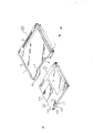
Fig. 1 represents a kind of transparent view of traditional overcoat box-like shape.
Fig. 2 is the part transparent view of the rough amplification on the outer surface of Classic box in the presentation graphs 1.
Fig. 3 is the part scheme drawing of rough amplification on the outer surface of expression Classic shown in Figure 1.
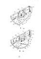
Fig. 4 represents one according to the overcoat box of disk cartridge of the present invention and the transparent view of a disk cartridge that will be loaded into.
Fig. 5 is a transparent view of looking, represent a kind of structure of disk cartridge shown in Figure 4 from the bottom.
Fig. 6 is the front elevation of the structure of expression overcoat box shown in Figure 4.
Fig. 7 is the back view of shown in Figure 4 cover of expression box structure.
Fig. 8 is the backplan of overcoat box structure shown in the expression.
Fig. 9 is the front elevation of expression overcoat box structure shown in Figure 4.
Figure 10 is a decomposition diagram of expression overcoat box structure shown in Figure 4.
Figure 11 looks, represents the transparent view of the top board spare structure of the disk cartridge overcoat box that formation is shown in Figure 4 from the bottom side.
Figure 12 is the lateral plan of a top board spare structure of expression.
Figure 13 is the lateral plan that expression constitutes a top board spare structure of disk cartridge overcoat box.
Figure 14 is the front elevation that expression constitutes a top board shape of disk cartridge overcoat box shown in Figure 4.
Figure 15 is the backplan of a top board spare shape of expression.
Figure 16 is the scheme drawing that expression constitutes a base plate shape of disk cartridge overcoat box shown in Figure 4.
Figure 17 is the front elevation of this floor piece shape of expression.
Figure 18 is the part transparent view of the amplification of expression floor piece shown in Figure 17.
Figure 19 is the part transparent view of a kind of improved amplification of this floor piece of expression.
Figure 20 is illustrated in the top board spare of side edge of disk cartridge overcoat box and the fragmentary cross-sectional view of floor piece engagement.
Figure 21 is illustrated in the top board spare of back of disk cartridge overcoat box and the fragmentary cross-sectional view of floor piece engagement.
Figure 22 is the another kind of improved transparent view that expression constitutes the floor piece of disk cartridge overcoat box.
Figure 23 looks, represents the transparent view of the locking piece shape of formation disk cartridge overcoat box from the front.
Figure 24 is the transparent view of looking from behind, represent this locking piece shape.
Figure 25 is the scheme drawing of expression locking piece shape shown in Figure 24.
Figure 26 is the scheme drawing that expression constitutes a floor piece shape of disk cartridge overcoat box.
Figure 27 is the expression disk cartridge is inserted the state of overcoat box in the error of the first kind mode a transparent view.
Figure 28 is the expression disk cartridge is inserted the state of overcoat box with second kind of wrong way a transparent view.
Figure 29 is the expression disk cartridge is inserted the state of overcoat box with the third wrong way a transparent view.
Figure 30 is the transverse cross-sectional view that the expression disk cartridge was contained in and remained on the state in its overcoat box.
Figure 31 is the longitudinal sectional drawing that the expression disk cartridge comprises and remain in the state in its overcoat box.
Figure 32 is that the expression disk cartridge is inserted in the overcoat box with a kind of wrong way and this wrong the insertion is the longitudinal sectional drawing of forbidden state.
Figure 33 is the expression disk cartridge is inserted the overcoat box in a kind of mode of mistake a transverse cross-sectional view.
Figure 34 is the longitudinal sectional drawing that expression disk cartridge overcoat box has been used the state of folded film encapsulation.
Figure 35 represents that folded film moves on to the longitudinal sectional drawing of a state of a side from the state of Figure 34 when disk cartridge overcoat box is packed with folded film.
Figure 36 represents that folded film moves on to the longitudinal sectional drawing of a state of a relative side from the state of Figure 34 when disk cartridge overcoat box is packed with folded film.
Figure 37 is the transverse cross-sectional view of expression overcoat box with the another kind of state of folded film encapsulation.
Figure 38 represents that folded film moves on to the longitudinal sectional drawing of a state of a side from state shown in Figure 37 when disk cartridge overcoat box encapsulates with folded film.
Figure 39 represents that folded film moves on to the longitudinal sectional drawing of a state of a relative side from state shown in Figure 37 when disk cartridge overcoat box encapsulates with folded film.
Figure 40 represents that tab member will be put into the transparent view of a kind of state on the overcoat box when overlapping box with folded film encapsulation is individual.
Figure 41 is the transparent view that the outer disc sleeve box of expression boxlike is used the state when folding the film encapsulation.
Figure 42 is the transparent view of a kind of improved shape of expression tab member.
Figure 43 represents that first kind of improved disk cartridge overcoat box locking piece is by the part transparent view of the amplification of the state of floor piece clamping according to the present invention.
Figure 44 is the part transparent view that another kind improves and locking piece is amplified by the mode of floor piece clamping of expression locking piece.
Figure 45 is that the expression locking piece is by the part scheme drawing of the amplification of floor piece clamping state.
Figure 46 represents that the bend arm of locking piece is by the part scheme drawing of the amplification of the state of elastic bending.
Figure 47 is the part transparent view of expression formation according to the another kind of improved amplification of a kind of locking piece of the overcoat box of disk cartridge of the present invention.
Figure 48 is the part scheme drawing of amplification of a kind of structure of expression locking piece shown in Figure 47.
Figure 49 is the transparent view of expression according to the amplification of the shape of the main portion of the outer condom box plate spare of the 4th kind of improved disk cartridge.
Figure 50 is the transparent view of expression floor piece shape shown in Figure 49.
Figure 51 is the longitudinal sectional drawing that the expression disk cartridge just is being inserted into the state in the outer box.
Figure 52 is the longitudinal sectional drawing that the expression disk cartridge has been inserted into overcoat box internal state.
Figure 53 is the lateral plan according to the structure of the top board spare in a kind of improvement of overcoat box of the present invention.
Figure 54 is the lateral plan of expression according to the floor piece structure in the another kind improvement of overcoat box of the present invention.
Figure 55 is the fragmentary cross-sectional view of amplification of the engagement of top board spare shown in expression Figure 53 and Figure 54 and the rear side between the floor piece.
Figure 56 is a decomposition diagram of the disk cartridge that is made of top board spare shown in Figure 53 and floor piece of expression.
Figure 57 is the transparent view of the amplification of the main portion shape of floor piece shown in expression Figure 54.
Figure 58 is the transparent view of improved amplification of the main portion shape of the floor piece of expression shown in Figure 54.
Figure 59 is the longitudinal sectional drawing that the expression disk cartridge just is being inserted into the mode in the box shown in Figure 56.
Figure 60 is the longitudinal sectional drawing that the expression disk cartridge has been inserted into the mode in the box shown in Figure 56.
Figure 61 is the part transparent view of expression according to the amplification of the main portion of the top board spare of the 4th kind of improved box.
Figure 62 is the part transparent view of the amplification of expression floor piece main portion.
Figure 63 is the part longitudinal sectional drawing of amplification of a bottom outlet structure of expression disk cartridge overcoat box.
Figure 64 is the part longitudinal sectional drawing of expression according to the amplification of the main portion of the 4th kind of improved overcoat box top board spare.
Figure 65 is the part longitudinal sectional drawing of expression according to the amplification of the 4th kind of improved overcoat box top board spare main portion.
Figure 66 is the part longitudinal sectional drawing of expression according to the amplification of the main portion of the improved overcoat box of another kind top board spare.
Figure 67 is expression be used for the casting section-drawing of amplification of main portion of metal die of top board spare and floor piece.
With reference to accompanying drawing, will be elaborated to some preferred embodiment of the present invention.
Fig. 4 represents a kind of overcoat box 100 according to disk cartridge 101 of the present invention.This disk cartridge 101 comprises a main cartridge 102 and is contained in one of them indicator, as CD or magnetooptical disc.
Employing is slidably mounted on the switch in a shutter member 105 control recording/reproducing holes 106,107 on the main cartridge 102.Shutter member 105 curves basically U-shaped by a kind of foil and forms, and comprises a pair of opening-closing plate that is used for opening and closing recording/reproducing hole 106,107.Opening-closing plate central web portion is connected to each other and stretches in parallel with each other.The central web portion of shutter member 105 is supported slidably by a side of main cartridge 102, so that opening-closing plate extends abreast to the surface of main cartridge.When shutter member 105 moved to the position of opening-closing plate and recording/reproducing hole 106,107 alignings, opening-closing plate will be closed recording/reproducing hole 106,107.Shown in arrow B among Fig. 4 and Fig. 5, shutter member 105 is slided with respect to the direction that disk cartridge 101 is inserted record/playback apparatus shown in Fig. 4 arrow A backward.The result is that the opening-closing plate of shutter member 105 moves on the first type surface of main cartridge 102 backward, thereby opens recording/reproducing hole 106,107.
On the center of the bottom major surface of main cartridge 102, form an annular bayonet socket 108.This bayonet socket 108 makes the clamp 115 of bayonet socket 114, clamping reference plane 116 and indicator 117 be exposed.
A pair of knock hole 112,113 is arranged on the bottom major surface of main cartridge 102, during appropriate location in disk cartridge is packed record/playback apparatus into, be used for locating disk cartridge.These holes 112,113rd form near the front and back end of the bottom major surface of main cartridge 102.
The bottom major surface of main cartridge 102 has pair of notches 110,109 and a dish type identification otch 111.Otch 110,109 is fit to cooperate with the sabot element of record/playback apparatus, blocks disk cartridge by this sabot element.These otch 110,109th form on two sides of the front side of main cartridge 102 bottom major surfaces, so that be opened on the side of main cartridge 102.Dish type identification otch 111 be form in the front side of main cartridge 102 bottom major surfaces so that be opened in the front side of main cartridge 102.According to the kind that is contained in the indicator 117 in the main cartridge, dish type identification otch 111 has certain depth.
According to the overcoat box of disk cartridge of the present invention is by constituting as the top board spare 1 of first parts with as the floor piece 2 of second parts, as shown in Fig. 4 and Fig. 6~10.
There is pair of inside wall components 11,12 top board spare 1 both sides in its lower section, and the side that is parallel to top plate portion 1a extends, as shown in figure 11.Top board spare 1 also has an interior rear wall member 15 that is parallel to the back of top plate portion 1a, as shown in figure 11. Madial wall parts 11,12 and interior rear wall member 15 are cast into one to limit an open circuited U-shaped periphery wall in front side with top plate portion 1a.The height that these sidewall sections 11,12 and rear wall section 15 are had is substantially equal to the thickness of main cartridge 102, and from the side of top plate portion 1a and back to the bias internal certain distance, this distance is corresponding to the thickness of these a few wall parts 11,12 and 15.
The side engagement rib 13,14 that outside horizontal expansion is arranged on the outer side edges of madial wall part 11,12 is as at Figure 11, shown in 12,14 and 15.These engagement ribs 13,14 are by extending back near the front side, and are parallel to the side of top plate portion 1a.These engagement ribs 13,14 be positioned at madial wall part 11,12 lower ends slightly by last position, and towards top plate portion 1a.
The fixed projection 23,24 that extends is backward arranged on the outer side edges of madial wall part 11,12.These fixed projections 23,24th are provided with towards the front side of madial wall part 11,12 near engagement rib 13,14 upper surfaces.The overhang of these fixed projections 23,24 is slightly smaller than the overhang of engagement rib 13,14.In these fixed projections 23,24 each all have one with the vertical front end face of sidewall sections 11,12 and one with respect to sidewall sections 11,12 bevelled aft end faces, its overhang reduces gradually towards rear side.
A pair of vertically extending otch 39,40 is arranged on the outer side edges of madial wall part 11,12.These otch 39,40 extend to the lower end from the near-end of madial wall part 11,12.
One offside shoulder 48,49 and back shoulder 50 are arranged on the lower surface of top plate portion 1a, and they lay respectively on dual-side and the back.These shoulders 48~50 are only outstanding just to be contacted with the middle part of top plate portion 1a slidably with the disk cartridge that prevents to insert in the overcoat box 100 a bit.
In the front side of top plate portion 1a an otch 5 is arranged, make the rear portion of the disk cartridge 101 that loads on call in the overcoat box 100 be exposed to the outside.
The lateral wall parts 17,18 that floor piece 2 has a pair of and side bottom parts 2a to extend in parallel on the dual-side on surface thereon, as shown in figure 10.Floor piece 1 also has an outer rear wall member 19 that is parallel to the back of bottom parts 2a. Lateral wall parts 17,18 and outer rear wall member 19 are cast into one with bottom parts 2a, thereby limit an open circuited U-shaped periphery wall in front.The height that these lateral wall parts 17,18 and rear wall section 25 are had is substantially equal to the thickness of main cartridge 102, and extends along side and the back of bottom parts 2a.
The side engaging groove 20,21 that inside extension is arranged in the inner side edge of side member 17,18 outside is as Figure 13, shown in 16 and 17.These grooves 20,21st, by near the front of lateral wall parts 17,18 towards the back, and be parallel to the upper surface of bottom parts 2a.These grooves 20,21st, side member 17,18 nearsides are slightly by forming on the last position outside, promptly on spaced slightly position with respect to bottom parts 2a, allow the upper end of groove 20,21 play the effect of engaged claw.Outside on the inboard of rear wall member 19, promptly on its front side edge, the flange 22 of an engaged claw after the outstanding conduct in front is arranged.Flange 22 is along the upper edge of outer rear wall member 19, and is parallel to bottom parts 2a upper surface, extended to another side by a side of outer rear wall member 19.Engaging groove after the lower side of flange 22 and bottom parts 2a constitute one.
The fixedly otch 25,26 that is used for inwardly opening is arranged respectively on the inner side edge of side member 17,18 outside.These are otch 25,26 and fixedly otch 23, the 24 front alignment of side member 17,18 outside fixedly, and communicates with the top of side engaging groove 20,21.Fixedly the degree of depth of each in the otch 25,26 is all shallow slightly than side engaging groove 20,21 for these.
Outside the upper side edge of side member 17,18 outer surfaces along on otch 37,38 is arranged, these otch are the upper side edge edges along side member 17,18, pass that the front of lateral wall parts 17,18 and back extend as ladder.The top of otch 37,38 is that the upper side edge of wall components 17,18 toward the outer side opens wide.
There are otch 41,42 a pair of and vertical incision 39,40 alignment at the rear portion of outside parts 17,18.These otch 41,42 from the upper end of lateral wall parts 17,18 to proximal extension.
There is an otch 6 in the front of bottom parts 2a, so that make the rear portion of the disk cartridge 101 in the overcoat box 100 of packing into be exposed to the outside.
On the side of base plate 2a and back, a pair of side stage rank 30,31 and backward step 32 are arranged respectively.When these steps 30~32 with a small amount of projection were used for preventing in disk cartridge 101 is packed overcoat box 100 into, disk cartridge 101 just contacted slidably with the middle part of bottom parts 2a.
On backward step 32, there is one to prevent the wrong projection of inserting 29.This projection is positioned on the position of departing from a little towards its side from the center of bottom parts 2a bottom parts 2a back.Prevent that wrong effect of inserting projection 29 will be explained below.
As shown in Figure 16 and 18, the continuous rib shape reinforcement 27,28 of a pair of and flange 22 is arranged at the both ends of flange 22.These reinforcements 27,28 are cast into one with the inside face of rear wall member 19, so that extend upwardly bottom parts 2a from flange 22.There are a plurality of sides to extend upwardly to the strengthening rib 43 of bottom parts 2a in the bottom of side engaging groove 20,21 from groove 20,21.
Simultaneously, reinforcement 27,28 as shown in figure 18 can be by constituting as shown in Figure 19.Outside the reinforcement 28a shown in Figure 19 is positioned on the whole surface of the flange 22 of rear wall member 19 and be positioned at the back engaging groove both sides.
As shown in Figure 22, top board spare 1 and floor piece 2 have two stepped appearance projections that separate each other with side member.These projections 59,60th, integrally formed with the upper surface of the form of rib and floor piece 2, and parallel with lateral wall parts 17,18.
As shown in Figure 20, by allowing side engagement rib 13,14 be engaged in the side engaging groove 20,21, and allow back engagement rib 16 be engaged between flange 22 and the bottom parts 2a (that is, afterwards engaging groove in) top board spare 1 and floor piece 2 are joined to one another.For mode like this connects top board spare 1 and floor piece 2, need top board spare 1 is placed floor piece 2 fronts, and side is meshed rib 13,14 rear side inserts backward mobile then top board spare 1 at the front end of side engaging groove 20,21, side engagement rib 13,14 is slided in side engaging groove 20,21.When sliding roof spare 1 when top plate portion 1a aligns with bottom parts 2a, engagement rib 16 in back is engaged in the engaging groove of back, simultaneously, fixed projection 23,24 and fixedly otch 25,26 engagements.For making fixed projection 23,24 and fixedly otch 25,26 engagements, at first these fixed projections 23,24 are put into space between the side member 17,18 from the front end of lateral wall parts 17,18, so that outwards pushing and and then depart from lateral wall parts 17,18 a little.When fixed projection 23,24 arrived position towards fixing otch, lateral wall parts 17,18 returned to its initial condition, so that mesh with fixed projection 23,24 in the fixing otch 25,26.
Two outer side edges of otch 37,38 that forms on the top of side component 17,18 and top plate portion 1a define side channel 7,8 outside.That is, as shown in figure 20, the side of the upper end of lateral wall spare 17,18 and top plate portion 1a is meshing with each other in the distance that equals otch 37,38 degree of depth to one section of bias internal.These side channels 7,8th overlap outward from the front that the right of box 100 side surfaces extends out.The back bottom of side channel 7,8 is formed by bottom outlet, and these bottom outlets are to be made of side channel 7,8 that forms on the side member 17,18 outside and the vertical incision 39,40 that forms on madial wall parts 11,12.
Simultaneously, being used for the casting nozzle of metal mold of casting top board spare 1 is G in as Figure 15
1A so-called bolt mouth that forms on the rear positions of the shown upper surface of being partial to top plate portion 1a slightly.Being used for the casting nozzle of metal mold of casting floor piece 2 is as Figure 16 G
2A so-called bolt mouth that forms on the position at the shown part of deflection chassis slightly 2a lower surface rear portion.That is, top board spare 1 and position casting nozzle similar with floor piece 2 shapes is in alignment with each other.So state is similar substantially owing to the caused distortion of cooling step (as shrinking) in injection molded process with floor piece 2 for top board spare 1, so the engagement rib of sidewall sections can cooperate each other glossily.Casting nozzle also can be so-called film mouth or liquid level end opening, to substitute the bolt mouth.In these cases, the casting nozzle on top board spare 1 and the floor piece 2 can be provided with so that substantially the same distortion (as shrinking) state to be provided with being in alignment with each other, thereby guarantees the smooth cooperation of top board spare 1 and floor piece 2.
Recess in the space between parts 1 and 2 has pair of locking part 9,10, is used for maintaining the disk cartridge 101 of packing between these parts 1 and 2.These are by locking piece 9,10th flexible and that elastomeric material (as polyacetal) constitutes, by end handle 44,45 and one across elastic arm 46 compositions of end handle 44,45, as shown in Figure 23~26.End handle 44,45th, columniform, and its axis is parallel to each other.Elastic arm 46 is arcs, and links to each other with end handle 44,45.Elastic arm 46 be with the direction of the axis normal of handle 44,45 on crooked.Crank arm 46 summit of arc is positioned at respect on handle 44,45 equidistant positions.The arc-shaped bend of locking piece 9,10 partly plays a part to maintain the partial fixing surface 47 of disk cartridge 101.
Locking piece 9,10th is fixed with a pair of locking piece part 33,34 that forms on floor piece 2.These locking piece fixed parts 33,34th form on the inner surface of the lateral wall parts 17,18 at place, the inner of recessed lateral wall spare 17,18, as shown in Figure 16.Clamping projection 54,55 before and after these connecting elements 33,34 all have.These clamping projections 54,55th, the bottom of lateral wall piece 17,18 forms outside, so that inwardly outstanding, continues up to bottom wall portion 2a.That is, these clamping projections 54,55 are located at the angle between lateral wall parts 17,18 and the bottom parts 2a.These clamping projections 54,55 are fixed Face to face in the distance that corresponds essentially to locking piece 9,10 length, and its both sides of facing have constituted holding tank 52,53 respectively.These holding tanks 52,53 are opened towards the top, and all have make its major axis along the part of front-rear direction oval or oblong cross section profile.Locking piece 9,10th, by allowing handle 44,45 snap in the holding tank 52,53, by 54,55 clampings of clamping projection.
These locking pieces 9,10 fixing should make the axle of handle 44,45 vertical with bottom parts 2a and allow the inboard of fixed surface 47 towards bottom parts 2a.That is, the arc-shaped bend arm 46 of locking piece 9,10 is suitable for interior side-prominent to bottom parts 2a.The arc-shaped bend arm 46 of these locking pieces 9,10 can elastic bending near the direction of lateral wall spare 17,18.When arm 46 in this way during resilient bias, handle 44,45 moves into respectively in the holding tank 52,53 along front-rear direction.
Simultaneously, the inner webs wall part 11,12 of top board spare 1 is cut at the rear portion, makes the rear portion lack certain distance apart from the top than middle part and front portion, and should be apart from the width of length corresponding to locking piece 9,10.So just prevented that madial wall spare 11,12 from leaning against on the locking piece 9,10 by 33,34 clampings of locking piece retained part, simultaneously, prevented that also locking piece 9,10 upwards is separated from locking piece retained part 33,34.
Notice, the dorsal part of locking piece fixed part 33,34, promptly so-called depression will be stood in the rear portion of the outer side edges of outer wall spare 17,18 in the one casting process of floor piece 2.The generation of this depression is owing to have the cooling stage of thickness in the injection molded process cause bigger than the other parts of lateral wall part 17,18, that therefore can inwardly shrink of some parts of the lateral wall parts 17,18 of locking piece fixed part 33,34.For preventing the generation of this depression,, breach 35,36 becomes hollow because having been arranged with the lateral wall parts 17,18 of locking piece fixed part 33,34 alignment that part of.
For disk cartridge 101 being packed into, the opening of disk cartridge 101 along direction shown in the arrow A among Fig. 4 from the front side packed into the space between floor piece 1a and the floor piece 2a according in the above-mentioned boxlike disc sleeve box 100 of the present invention and remain on wherein.
When the front of disk cartridge 101 arrives the back of overcoat box 100, main cartridge 102 side surfaces in front be inserted into locking piece 9,10 fixed surface 47,48 so that arm 46,46 along direction skew near outer webs part 17,18.When the front of main cartridge 102 arrived the desired location that leans against basically on overcoat box 100 inwalls, locking piece 9,10 was aimed at otch 110,109.At this moment, the arm 46,46 of locking piece 9,10 returns to its initial condition under himself elastic force effect, and fixed surface 47,47 and otch 110,109 are cooperated.By means of the fixed surface 47,47 of locking piece 9,10 and the cooperation of otch 110,109, then disk cartridge 101 is held, and has limited out of gear mesh backward moving, and has promptly limited and deviate from moving of overcoat box 100 under collision or vibration from opening.
As shown in Figure 31, at this moment, will forbid that the projection 29 that mistake is inserted is contained in the dish identification mouth 111 of disk cartridge 101.
Placed now the disk cartridge 101 of outer box 100 to be accommodated between parts 1 and 2 and obtained protection from the outside of parts 1 and 2.
When a plurality of overcoat boxes 100 were loaded in the support that is suitable for holding a plurality of overcoat boxes, they were to be held in place by side channel 7,8.By the cooperation of the adapting device on the support, overcoat box 100 can unexpectedly not removed from support with the bottom outlet that constitutes by otch 41,42.
When the disk cartridge 101 in the overcoat box 100 of packing into will be taken out from overcoat box 100, arrest the rear portion of the disk cartridge 101 that is exposed by otch 5,6 with finger, and pull back with respect to overcoat box 100.Do making the fixed surface 47,47 of locking piece 9,10 be advanced like this, make the arm 46,46 of locking piece 9,10 near the direction of lateral wall parts 17,18, produce skew simultaneously, so that discharge fixing to disk cartridge 101 by the front side edge of main cartridge 102.Like this, disk cartridge 101 just can be removed from opening.When disk cartridge 101 was moved further backward, locking piece 9,10 was got back to its initial condition.Disk cartridge 101 can be continued to move backward, so that from overcoat box 100, take out.
Describe now for the mechanism that prevents that disk cartridge from packing in the overcoat box mistakenly of the present invention.
Even overcoat box 100 of the present invention is designed to disk cartridge 101 when being inserted mistakenly by opening, can prevent that also disk cartridge 101 is completely enclosed in the overcoat box 100.
Three kinds of possible disk cartridge, 101 wrong situations about inserting are arranged, that is to say, by direction shown in the arrow D among Figure 27, with disk cartridge 101 bottom major surfaces up and the front end one side situation of packing into earlier, by direction shown in the arrow E among Figure 28, with disk cartridge 101 bottom major surfaces up and the rear end one side situation of packing into earlier, and by direction shown in the arrow F among Figure 29, with disk cartridge 101 top major surfaces up, and the situation that rear end one side is packed into earlier.
In any of these situation, when disk cartridge 101 was loaded in the overcoat box 100, locking piece 9,10 made locking piece 9,10 keep advanced state, and is subjected to the resilient bias of main cartridge 102, as shown in Figure 33 not by 110,109 containings of groove.If locking piece 9,10 is in the resilient bias state in long-time, then locking piece 9,10 will stand plastic deformation, makes the disk cartridge 101 of packing on the normal position to clamp for locked 9,10.
With regard to this overcoat box 100, if disk cartridge 101 is inserted into a kind of above-mentioned wrong way, the projection 29 that suppresses wrong insertion is abutted against on the main cartridge 102 to stop it to be inserted in the overcoat box 100, as shown in Figure 32, that is, to lack than the thickness (as in Fig. 2, representing) of main cartridge 102 to the distance (as represented by arrow L among Figure 32) of the lower surface of top plate portion 1a by arrow T from the upper surface that suppresses mistake insertion projection 29.So dish-type identification otch 111 is met less than suppressing the wrong projection 29 of inserting.If projection 29 does not mesh with otch 111, then will make projection 29 insert overcoat boxes 100 to stop disk cartridge 101 near living main cartridge 102.Simultaneously, the height of projection 29 is lower than the degree of depth of dish-type identification otch 111.
Adopt as at the method for packing as shown in Figure 34~41, the above-mentioned overcoat box 100 that disk cartridge 101 is housed is encapsulated with folded film 201.Folded film 201 is a kind of heat shrink films, and is collapsible when it is heated, fusible when further heating.
In order to encapsulate, can apply a paper label spare 204(at the front end of overcoat box 100 can be a sheet shaped piece) so that cover otch 5 and 6.Tab member 204 is converted into U-shaped from the center and is added on the overcoat box 100 to cover its top plate portion 1a and bottom parts 2a.Two parallel bending parts of tab member 204 are located substantially on its middle position, and one section distance corresponding to the thickness of overcoat box 100 of each interval.After being added in tab member 204 on the overcoat box 100, overcoat box 100 promptly presents a smooth outer surface.
Simultaneously, tab member 204 is used as so-called index tab.As the tab member 204 of index tab is to be made of with the coherent tearable paper of label a kind of label that scribbles lining cement and one.
Packing is so-called caramel packing.At first, overcoat box 100 is put into folded film 201 inside that link to each other and obtain by two opposite side with the two halves film.The both ends that are folded film 201 cylindraceous bend inwards to form lap 202,203, as shown in Figure 37.Adopt the hot iron parts 301,302 of a pair of formation packing device, this lap 202,203 is heated and fuse together by hot weld.These laps 202,203rd form on the outer surface of overcoat box 100 side components.
Hot iron parts 301,302nd are made of metal, and install face-to-face.These hot iron parts 301,302 are heated to predetermined temperature and move relative to each other to change its spacing.These hot iron parts 301,302 have otch 303,304 respectively on its opposite side.The profile of these otch 303,304 conforms to the appearance profile of overcoat box 100 side surfaces, so that the dual-side of overcoat box 100 is deep into kerf bottom.Because the edge of overcoat box 100 side surfaces is slick and sly, so two angles of otch 303,304 also are the cylindrical to present of slyness.
Otch 303,304 appearance profile allows the edge of overcoat box 100 to insert wherein, consequently, if move folded film 201 along one or another direction, the one end is extended on the whole side surface of overcoat box 100 up to offside, and promptly top plate portion 1a or bottom parts 2a fold the extendible portion of film and can also use hot iron parts 301, thereby 302 heating are by hot weld, as shown in Figure 35 and 36.
Folded film 201 is heated and shrinks so that closely be applied on the surface of overcoat box 100 to finish packing, as shown in Figure 41.Because overcoat box 100 presents a smooth outside face, folded film 201 can closely be attached on the outer surface of the overcoat box 100 that adds tab member 204 in advance in the above.
Simultaneously, the lap 202,203 of folded film 204 covers side channel 7,8, as shown in Figure 34.That part of of overlapping parts 202,203 that is placed on the side channel 7,8 do not pushed fully by hot iron parts 301,302, so the possibility that exists these parts not fuse together.
May occur that promptly folded film 201 is partly placed towards the one side or the another side of overcoat box 100, shown in Figure 35 and 36.Under these situations, the width of a lap among the lap 303,304 becomes narrower than the width of side channel 7,8, and as at Figure 35, arrow R is represented in 36.Yet because side channel 7,8 more is partial to top plate portion 1a than the midway location of side component, the position of lap 202,203 is not on side channel 7,8, so lap 202,203 is fused together reliably.
Notice that the sheet shaped piece that is adopted also can be the tab member 205 that is suitable for only covering the front side of overcoat box 100, as shown in FIG. 2 in according to method for packing of the present invention.Rather than as previously mentioned, cover top plate portion 1a and bottom parts 2a.Tab member 205 has two parallel liness, and is converted into U-shaped.Folded part is from tab member 205 centers deflection one hand hay cutter, and two apart segment distances of tabs, and this distance is corresponding to the thickness of overcoat box 100.When overcoat box 100 usefulness tab member 205 cover, present a smooth outside face.
After this various improvement according to disk cartridge overcoat box of the present invention will be described.With represent with identical reference number at the 100 similar parts of the overcoat box shown in Fig. 4, and for the tube just for the purpose of, omitted identical description.
First kind of improvement according to disk cartridge overcoat box of the present invention at first is described.Locking piece 9,10 is fixed on the locking piece hold assembly 33,34 of a pair of floor piece 2 formation.These locking piece hold assemblies 33,34th form on the rear portion on side member 17,18 opposed inside limits, as shown in Figure 16 outside.These locking piece hold assemblies 33,34 have forward and backward clamping projection 54,55, as at Figure 43, shown in 44.These clamping projections 54,55th, the bottom of side member 17,18 forms outside, so that inwardly continue to extend to bottom wall portion 2a.That is, these clamping projections 54,55 are located at the angle between lateral wall parts 17,18 and the bottom wall portion 2a.At interval these clamping projections 54,55 are fixed with facing each other with a distance that corresponds essentially to locking piece 9,10 length.The side that clamping projection 54,55 is faced has holding tank 52,53 respectively.These holding tanks 52,53 all have rounded basically inside face and to having major axis along the part ellipse of fore-and-aft direction or the open-top of long round section profile.The difference of the major and minor axis of the elliptic cross-section profile of holding tank 52,53 zones of action is about for example 0.3 millimeter, has the words of about 1.2 mm dias as carpopodium 44,45.
By allowing end handle 44,45 and holding tank 52,53 cooperate, make locking piece 9,10 be held projection 54,55 clampings.The location of these locking pieces 9,10 be allow handle 44,45 the axle perpendicular to base plate part 2a, fixed surface 47 then points to bottom parts 2a.Be that the arc of these locking pieces 9,10 is cranked arm and 46 is suitable for extending to the inboard of bottom parts 2a.
As shown in Figure 46, locking piece 9,10 is designed to that (as arrow indication in Figure 46) can produce resilient bias on the direction of convergence lateral wall spare 17,18.When cranking arm 46 in this way during resilient bias, end handle 44,45 moves in the holding tank 52,53 along fore-and-aft direction.Offside at each locking piece 9,10 fixed surface 47 has a boss 58.When arm 46 during along the direction resilient bias of arm member 17,18 toward the outer side, boss 58 abuts against the summit of the supporting rib 57 at hold assembly 33,34 middle parts that are located at each locking piece, with the resilient bias that prevents that arm 46 is excessive, as shown in Figure 46.Rib 57 is on the inside face of each lateral wall spare 17,18 and vertically extending between clamping projection 54,55.
The rear end of top board spare 1 folding madial wall spare 11,12 is cut so that the distance that lateral wall piece 11,12 is hung from top plate portion 1a at notch is shorter than in middle part and the anterior distance that hangs, so that vacate a space that equals each locking piece 9,10 width.That is, the locking piece 9,10 that madial wall parts 11,12 are thrown off by 33,34 clampings of locking piece hold assembly has prevented the upwards disengagement from locking piece hold assembly 33,34 of these locking pieces 9,10 simultaneously.
According to the connecting element in the disk cartridge overcoat box 100 of the present invention can also be as shown in Figure 44 locking piece 9,10, and 46 the middle part of wherein cranking arm is flat at 56 places, thereby substitutes the locking piece shown in the embodiment 9,10 in front.The back will illustrate second kind of improvement according to boxlike box overcoat box of the present invention.
The middle part of these locking pieces 9,10 is designed to can be used to and groove 110,109 ingear anchor fittings.When disk cartridge 101 was loaded in the overcoat box 100, locking piece 9,10 was advanced by the front side surface of main cartridge 102, thereby made the 46 generation resilient bias of cranking arm.During desired location in main cartridge 102 is inserted into overcoat box 100, cranking arm 46 returns to its initial condition so that anchor fitting is engaged in the groove 110,109.The locking piece 9,10 that its fixed parts is engaged in the groove 109,110 has prevented that disk cartridge 101 is deviate under impact or vibration situation from overcoat box 100.
Because the fixed parts of locking piece 9,10 has straight surface, so when disk cartridge 101 is loaded into overcoat box 100, slide on main cartridge 102 to guarantee that disk cartridge smoothly and easily inserts overcoat box 100 in this plane 56.
The connecting element of overcoat box 100 can also be designed to the locking piece 60 integrally formed with floor piece 2, thereby replaces the locking piece 9,10 that forms respectively on floor piece 2 shown in the embodiment example in front.The following describes the third improvement of disk cartridge overcoat box.
These locking pieces 60 are double-type, and are to form face-to-face on the interior rear surface of lateral wall piece 17,18 outside.To be of forming in the bottom of lateral wall piece 17,18 outside be plate parts along what fore-and-aft direction extended to locking piece 60 basically.The front side of these locking pieces 60,60 and lateral wall spare 17,18 form one, and its rear end is a free end.Locking piece 60 can produce resilient bias with front end as fulcrum on the direction of wall components 17,18 toward the outer side, as shown in Figure 48 arrow D.Have the space of aliging on the inside face of lateral wall parts 17,18 and produce resilient bias to allow these locking pieces 60 with locking piece 60.
The middle part of these locking pieces 60 is with the interior curve of trapezoidal basically mode to bottom parts 2a.The middle part of locking piece 60 is as forming with otch 110,109 ingear anchor fittings.When disk cartridge 101 was put in the overcoat box 100, the progradation by 102 liang of front side edge of main cartridge made locking piece 60,60 produce resilient bias.When main cartridge 102 was loaded on the desired location in the overcoat box 100, locking piece 60 returned to its initial condition and meshes to allow anchor fitting and otch 110,109.Make anchor fitting and otch 110,109 ingear locking pieces 60,60 prevent that disk cartridge 101 is deviate under collision or vibration situation from overcoat box 100.
The anchor fitting of locking piece 60 has an anterior bevelled surface 62 towards disk cartridge 101 direction of insertion, as among Figure 48 shown in the arrow C, the degree of dip on this inclined-plane is more slow than relative back bevel, disk cartridge 101 is inserted outer boxes 100 or when therefrom taking out, make locking piece 60 more easily produce resilient bias with box lunch.
The 4th kind of improvement according to disk cartridge overcoat box of the present invention will be described below.
For disk cartridge 101 being held and is remained in the overcoat box 100 according to above-mentioned the 4th embodiment, with disk cartridge 101 by the opening on the overcoat box 100 in the front side is packed (as Fig. 4 shown in the arrow A) space between top plate portion 1a and bottom parts 2a into.
When arriving the rear end of overcoat box 100 for the front portion of disk cartridge 101, the front end towards main cartridge 102 sides of locking piece 9 advance locking piece 9 fixed surface 47 so that arm 46 outside lateral wall pieces 17 be offset.At this moment, the front end of main cartridge 102 opposite side surfaces abuts against the outer surface of locking piece boss 70, so that move to locking piece 9 slightly.When the front of main cartridge 102 entered into desired location on the madial wall part 15 that leans against overcoat box 100 basically, locking piece 9 and locking boss 70 ran into otch 109,110 respectively.This is engraved in the arm 46 of locking piece 9 under himself bullet effect, return to its initial condition, and fixed surface 47 is got in the otch 109, as shown in Figure 52.Locking piece 9 is pushed main cartridge 102 to offside, so that locking piece boss 70 extend in the offside otch 110.
Width less than the main cartridge of being represented by arrow w among Figure 52 102 should be selected to the distance the locking boss 70 outside face summits in the summit of the fixed surface of being represented by arrow Lc among Figure 52 47.So the fixed surface 47 of locking piece 9 and locking boss 70 enter after the otch 109,110, by two sides clamping main cartridge 102 it is maintained, thereby prevented that the opening part from overcoat box 100 drops to the outside under collision or vibration situation.
This moment, stop the wrong projection of inserting 29 to be engaged in the dish-type identification otch 111 of disk cartridge 101.
So disk cartridge 101 in place is comprised between plate 1 and 2 and by its protection in overcoat box 100.In order from overcoat box 100, to take out disk cartridge 101, the disk cartridge rear portion that is exposed is pulled back with respect to overcoat box 100 by otch 5,6.The fixed surface 47 of locking piece 9 is advanced by the front portion of main cartridge 102 side surfaces then, so that arm 46 outside lateral wall piece 17 bendings are to discharge fixing main cartridge 102.At this moment, disk cartridge 101 can be taken out from overcoat box 100 by opening.If disk cartridge 101 further moves backward, locking piece 9 returns to its initial condition.Being pulled outwardly disk cartridge just can take out it from overcoat box 100.
With regard to the overcoat box 100 of present embodiment, lateral wall piece 11,12,17,18 as shown in Figure 56 remove rear portion L
2An area L in addition
1On mesh together.That is, with regard to this disk cartridge overcoat box 100, the rear portion of top board spare and floor piece produces resilient bias on separated direction. Rear wall member 15,19 can also be except two side area L shown in Figure 56
3Central area L in addition
4The place is engaged with each other, and in this case, two side areas of top board and floor piece can produce resilient bias in rearward end along the direction that is separated from each other.
In disk cartridge 101 is packed overcoat box 100 into, when making the front end of disk cartridge 101 arrive the rear end of overcoat box 100, two front side edge of main cartridge 102 bottom parts promote locking boss 71,71 upper surface so that bottom parts 2a offset downward, promptly away from top plate portion 1a.At this moment, the broadening during than initial condition of the rear portion of side channel 7,8 is as being pointed out by arrow C in Figure 59.When the front end of main cartridge 102 entered desired location on the madial wall spare 15 that leans against overcoat box 100 basically, bottom parts 2a ran into otch 109,110.As shown in Figure 60, this moment, bottom parts 2a returned to its initial condition under himself elastic force effect, and 71,71 of locking boss and otch 109,110 engagements.
Should select less than width by the distance between locking boss 71,71 end faces of arrow Lc indication among Figure 59 by the main cartridge 102 of arrow w indication among Figure 52.So therefore, by allowing locking boss 71,71 enter otch 109,110, it is maintained, and has prevented that under collision or vibration situation main cartridge 102 opening by overcoat box 100 is from wherein dropping to the outside by two sides that clamp main cartridge 102.
In order from overcoat box 100, to take out disk cartridge 101, pull back with respect to overcoat box 100 by the rear portion of otch 5,6 with the disk cartridge that is exposed.Then the locking boss 71,71 of locking piece 9 is advanced by the front portion of main cartridge 102 side surfaces, thereby makes the rear portion of bottom parts 2a produce skew release by locking the fixing of 71,71 pairs of main cartridges 102 of boss on away from the direction of top plate portion 1a.At this moment, can from overcoat box 100, take out disk cartridge 101 by opening.If further mobile backward disk cartridge 101, locking piece 9 will be got back to its initial condition.It can be taken out from overcoat box 100 by being pulled outwardly disk cartridge 101.
If for this overcoat box 100, on two sides of main box spare, form the words of pair of locking boss, so, these lock tab platforms are triangular in shape basically, and its triangle end face is parallel to lateral wall spare 17,18 extend, and its upper limb is by being limited from the inclined-plane that projects upwards away from bottom parts 2a.
The 5th kind of improvement according to disk cartridge overcoat box of the present invention will be described below.
In the back outer surface of top board spare 1 madial wall spare 11,12, form the otch 80,81 of a pair of qualification bottom outlet.This otch 80,81st forms as the groove near (promptly from the lower surface of top plate portion 1a to the lower end of madial wall spare 11, the 12) extension to the lower end of the nearside of madial wall spare 11,12, as shown in Figure 61.
There is pair of notches 82,83 at rear portion at the lateral wall spare 17,18 of floor piece 2, is used for determining bottom outlets with otch 80,81 alignment.This otch 82,83rd forms on the direction of near-end in the upper end from lateral wall spare 17,18, as shown in Figure 63.
On the other hand, outside near the area limiting the side of the otch 37,38 that forms of the upper end of lateral wall piece 17,18 outer surfaces and top plate portion 1a side channel 7,8.That is, the top of lateral wall spare 17,18 abuts against on the side of top plate portion 1a, as shown in Figure 20 on the position of the distance that equals otch 37,38 degree of depth to one section of bias internal.These side channels 7,8 extend to the back-end from the front of overcoat box 100 sides.
In these side channels 7,8, insert the supporting member (not shown) of the support that is used for holding and support a plurality of overcoat boxes 100.That is,, allow supporting member be inserted into support is supported above-mentioned overcoat box 100 by supporting member.
Rear side in these side channel 7,8 bottoms has the bottom outlet that is limited by the otch on the lateral wall spare 17,18 82,83, and this otch 80,81 of cutting on hole 82,83 and the madial wall spare 11,12 overlaps.
By allowing the meshing part of support mesh in bottom outlet, these bottom outlets have played the effect of blocking overcoat box 100.The degree of depth that these bottom outlets had is enough to allow meshing part to be engaged on wherein.By the degree of depth of the bottom outlet of arrow G indication among Figure 63 the degree of depth and lateral wall spare 17,18 thickness sums, as shown in Figure 63 corresponding to otch 80,81.It is dark that the thickness of the thickness of this depth ratio lateral wall 17,18 or madial wall spare 11,12 is wanted.
The following describes the 6th kind of improvement according to disk cartridge overcoat box of the present invention.In this improvement, side channel 7,8 be not limited to picture in front among the embodiment by top plate portion 1a and otch 37,38 those side channels 7,8 that limited, but can be by lateral wall parts 17,18 upper surface, the end near zone of the lateral surface of madial wall spare 11,12 and top plate portion 1a limits, in this case, madial wall parts 11,12 lower end abuts against on the bottom parts 2a, and is provided with stepped appearance bearing 85 in its outside, as shown in Figure 64. Lateral wall parts 17,18 do not have otch 37,38, but have flat upper surface.The upper part of lateral wall parts 17,18 leans against on the lower surface of bearing 85, and its inner surface leans against on the outer surface of madial wall parts 11,12 simultaneously.
If by the upper surface of lateral wall parts 17,18, the end near zone of the lateral surface of madial wall parts 11,12 and top plate portion 1a limits side channel 7,8, and then madial wall parts 11,12 can not contain bearing 85, as shown in Figure 65.In this case, lateral wall parts 17,18 can be close to and support the bottom of the outer surface of madial wall parts 11,12.
In addition, the jut (as flange 22) because the otch of formation side channel 7,8 makes progress, so can carry out molding with a kind of metal paattern with simple structure, promptly this metal paattern only is made of a patrix 501 and a counterdie 502, and does not establish the slip core, as shown in Figure 67.
Adopt this improvement, because madial wall parts 11,12 lower end leans against on the bottom parts 2a, outside parts 17,18 upper end can lean against on the top plate portion 1a, and lateral wall parts 17,18 lean against and be bearing in madial wall parts 11, on 12 the outer surface, then can obtain the mechanical strength of higher disk cartridge overcoat box.
Claims (24)
1, a kind of overcoat box of disk cartridge comprises
One has the first half of square plate part, and it also has a pair of sidewall sections that forms along the parallel edges of described plate part and one by the rear wall section that limits between the described sidewall sections,
First geared assembly that on described sidewall sections, forms,
Second geared assembly that on described rear wall section, forms,
One has the second half of square plate part, and it also has a pair of sidewall sections that forms along the parallel edges of described plate part and one by the rear wall section that limits between the described sidewall sections,
What form on described the second half described sidewall sections is used for and the described first geared assembly ingear geared assembly,
What form on described the second half described rear wall section is used for and the described second geared assembly ingear geared assembly, and
Be used for keeping described disk cartridge holding device in place in described overcoat box.
2, overcoat box according to claim 1 further comprises,
When described second geared assembly when being used for meshing its described device engagement, be used for the described first half-sum described second semifixed blocking device together.
3, overcoat box according to claim 1, it is characterized in that: described first geared assembly comprises projection and the groove that the limit that is parallel to described the first half described square plate part forms, and be used for comprising the projection that is engaged in described first geared assembly with the described device of the described first geared assembly ingear and be engaged on groove in the projection of described first geared assembly, described protrusions parallel is in the groove of described first geared assembly.
4, as overcoat box as described in the claim 3, it is characterized in that: described second geared assembly comprises a side-prominent projection in described the first half that is forming on the far-end of described the first half rear walls, and otch that between described the first half described square plate part and described projection, forms, and the described described device that is used for meshing described second geared assembly comprises that one is engaged on projection in described the first half the described otch at the far-end of described the second half described rear wall to described the second half outstanding being used in the outside, and an otch that forms between described the second half described projection and described the second half described square plate part.
5, overcoat box according to claim 1 further comprises: a pair of groove that forms on its lateral wall.
6, overcoat box according to claim 1, it is characterized in that: described a pair of groove comprises being used for and the described device of the described first geared assembly ingear of described first geared assembly.
7, overcoat box according to claim 1 is characterized in that described holding device comprises that at least one is located at the holding device on described the second half.
8, as overcoat box as described in the claim 7, it is characterized in that: described the second half also comprise the notch portion that a described holding device provides, when described device that described second geared assembly and being used for meshes described second geared assembly during with the described holding device engagement that is contained in one of pair of sidewalls of described the second half, described notch portion is closed.
9, overcoat box according to claim 1 is characterized in that: described holding device comprises a pair of a pair of retained part that forms on described the second half inboard.
10, overcoat box according to claim 1 is characterized in that: described holding device comprises a pair of a pair of retained part that forms on described the second half inboard.
11, as overcoat box as described in the claim 6, it is characterized in that: described the second half also comprise and stop wrong device of packing into.
12, as overcoat box as described in the claim 5, it is characterized in that: described the second half also comprise the stiffening device that is used for strengthening described rear wall.
13, a kind of overcoat box of disk cartridge comprises:
One the first half; It has a square plate part; The pair of flanges that an a pair of opposite side along being parallel to described square plate part forms; Be parallel to that the described limit of described square plate part forms and than the edge of described square plate part more to the pair of sidewalls part of bias internal; Be used for the edge of the described plate part of ratio that links to each other with described sidewall sections more to a wall section of bias internal; And a plurality of flanges that between described sidewall sections, described wall section and described square plate part, form
First geared assembly that on described the first half described sidewall sections, forms,
Second geared assembly that on described the first half described sidewall sections, forms,
One the second half, it has a square plate part, with from the parallel edges of described plate part straight down the pair of sidewalls part and be used for linking to each other with described sidewall sections from a described square plate part wall portion straight down of described the second half,
What form on described sidewall sections is used for and the described first geared assembly ingear device,
What form in described the second half described wall portion is used for and the described second geared assembly ingear device, and
Be used for making the holding device of described disk cartridge fix in position in described overcoat box.
14, as overcoat box as described in the claim 13, it is characterized in that also comprising a pair of a pair of groove that on the lateral wall of overcoat box, forms.
15, as overcoat box as described in the claim 14, it is characterized in that: described sidewall sections has otch, and described groove comprises described the first half described flange and described the second half described otch.
16, as overcoat box as described in the claim 14, it is characterized in that each described groove part has notch portion.
17, as overcoat box as described in the claim 13, it is characterized in that described first geared assembly comprises projection and groove that the side that is parallel to described the first half described square plate part forms, and be used for comprising the projection in the groove that is engaged on described first geared assembly with the described device of the described first geared assembly ingear and be engaged on groove in the projection of described first geared assembly, described protrusions parallel is in the groove of described first geared assembly.
18, as overcoat box as described in the claim 17, it is characterized in that described second geared assembly comprises a side-prominent projection in described the first half that is forming on the far-end of described the first half rear walls, and otch that between described the first half described square plate part and described projection, forms, and be used for described device with described second geared assembly comprise one outstanding to described the second half outsides at the far-end of described the second half described rear wall, be used for being engaged on the projection in described the first half the described otch, and an otch that between described the second half described projection and described the second half described square plate part, forms.
19, as overcoat box as described in the claim 13, it is characterized in that: described holding device comprises at least one holder of the angle that forms between the described plate part of the described part that is located at described wall portion and described the second half.
20, as overcoat box as described in the claim 14, it is characterized in that: further comprise the device that the prevention mistake of the angle between the described plate part that is located at described wall portion and described the second half is packed into.
21,, it is characterized in that also comprising that the size of one of described otch is greater than another from the pair of notches that forms with each double-type side of described wall portion of described the first and second half in described plate part as overcoat box as described in the claim 13.
22, a kind of have an opening and one from the method for packing of opening to the overcoat box of the inboard otch that forms of overcoat box, may further comprise the steps: a sheet shaped piece is added a cover on described at least opening and described otch, apply a kind of reel like film, make on the side of overcoat box, to form lap, heat the end fusion that described lap makes described film.
23,, it is characterized in that also comprising the described lap of heating so that the end fusion of described film and the step that heats whole parts as method for packing as described in the claim 22.
24, a kind of have an opening, and the method for packing of the overcoat box of an a pair of groove that forms to the inboard otch that forms of overcoat box with at each sidewall of overcoat box from opening may further comprise the steps:
A sheet shaped piece is added a cover on described at least opening and described otch,
Apply heat-shrinkable film, make on the position of departing from the groove on the overcoat box side, to form lap, and
Heat described lap so that allow the end of described film fuse.
Applications Claiming Priority (8)
| Application Number | Priority Date | Filing Date | Title |
|---|---|---|---|
| JP4103958A JP3039128B2 (en) | 1992-03-31 | 1992-03-31 | Packaging method |
| JP103959/92 | 1992-03-31 | ||
| JP10395992A JP3331618B2 (en) | 1992-03-31 | 1992-03-31 | Disk cartridge case |
| JP10396592A JP3189371B2 (en) | 1992-03-31 | 1992-03-31 | Disk cartridge case and packaging structure |
| JP103960/92 | 1992-03-31 | ||
| JP103958/92 | 1992-03-31 | ||
| JP103965/92 | 1992-03-31 | ||
| JP10396092A JP3271080B2 (en) | 1992-03-31 | 1992-03-31 | Disk cartridge case |
Related Child Applications (1)
| Application Number | Title | Priority Date | Filing Date |
|---|---|---|---|
| CN98109270A Division CN1219735A (en) | 1992-03-31 | 1998-05-22 | Casing for housing disc cartridge and method for packaging the casing |
Publications (2)
| Publication Number | Publication Date |
|---|---|
| CN1081993A true CN1081993A (en) | 1994-02-16 |
| CN1043630C CN1043630C (en) | 1999-06-16 |
Family
ID=27469170
Family Applications (2)
| Application Number | Title | Priority Date | Filing Date |
|---|---|---|---|
| CN93105480A Expired - Fee Related CN1043630C (en) | 1992-03-31 | 1993-03-31 | Casing for housing disc cartridge and method for packaging the casing |
| CN98109270A Pending CN1219735A (en) | 1992-03-31 | 1998-05-22 | Casing for housing disc cartridge and method for packaging the casing |
Family Applications After (1)
| Application Number | Title | Priority Date | Filing Date |
|---|---|---|---|
| CN98109270A Pending CN1219735A (en) | 1992-03-31 | 1998-05-22 | Casing for housing disc cartridge and method for packaging the casing |
Country Status (9)
| Country | Link |
|---|---|
| US (3) | US5450952A (en) |
| EP (2) | EP0564155B1 (en) |
| KR (1) | KR100271552B1 (en) |
| CN (2) | CN1043630C (en) |
| AT (2) | ATE170661T1 (en) |
| AU (2) | AU665986B2 (en) |
| DE (2) | DE69320676T2 (en) |
| HK (1) | HK1013505A1 (en) |
| PH (1) | PH29973A (en) |
Cited By (1)
| Publication number | Priority date | Publication date | Assignee | Title |
|---|---|---|---|---|
| CN108298207A (en) * | 2017-01-11 | 2018-07-20 | 丰田自动车株式会社 | Packaging structure and packing method for plate heater and harness |
Families Citing this family (24)
| Publication number | Priority date | Publication date | Assignee | Title |
|---|---|---|---|---|
| AU665986B2 (en) * | 1992-03-31 | 1996-01-25 | Sony Corporation | Casing for housing disc cartridge and method for packaging the casing |
| US5377827A (en) * | 1992-06-22 | 1995-01-03 | Queens Group, Inc. | Media disk storage container with printed paperboard sheets |
| EP0632454A1 (en) * | 1993-05-31 | 1995-01-04 | Sony Corporation | Disc cartridge container casing |
| US5520279A (en) * | 1994-12-30 | 1996-05-28 | Lin Shih Hsien | Compact disk carrying container |
| AU687123B2 (en) * | 1995-01-06 | 1998-02-19 | Shih-Hsien Lin | A compact disk carrying container |
| JPH08324669A (en) * | 1995-05-31 | 1996-12-10 | Sony Corp | Recording medium package |
| USD412261S (en) | 1995-07-20 | 1999-07-27 | Q2 Marketing, Llc | Video disk storage package |
| US6243350B1 (en) * | 1996-05-01 | 2001-06-05 | Terastor Corporation | Optical storage systems with flying optical heads for near-field recording and reading |
| DE29616895U1 (en) * | 1996-09-27 | 1996-12-12 | Siemens Ag | Transport container for relays |
| WO1998019305A1 (en) | 1996-10-26 | 1998-05-07 | Digisox Limited | A holder for a planar data storage medium |
| GB9622316D0 (en) * | 1996-10-26 | 1996-12-18 | Butcher Sean | Discsox |
| JPH10310187A (en) * | 1997-05-08 | 1998-11-24 | Tdk Corp | Cartridge housing case |
| JPH1149271A (en) * | 1997-07-31 | 1999-02-23 | Sony Corp | Sleeve-type cartridge housing case |
| US5954198A (en) * | 1997-10-28 | 1999-09-21 | Tdk Corporation | Cartridge receiving casing |
| US6095327A (en) * | 1998-02-02 | 2000-08-01 | Tdk Corporation | Storage case for cartridge, manufacturing method thereof and cartridge |
| JPH11232817A (en) * | 1998-02-09 | 1999-08-27 | Sony Corp | Housing case for disk cartridge |
| JP3519593B2 (en) * | 1998-02-27 | 2004-04-19 | Tdk株式会社 | Cartridge and cartridge storage case |
| JPH11321960A (en) | 1998-05-18 | 1999-11-24 | Sony Corp | Disk cartridge storage case |
| SG94718A1 (en) | 1998-05-23 | 2003-03-18 | Samsung Electronics Co Ltd | Cartridge for an information recording medium |
| JP2000103490A (en) * | 1998-07-30 | 2000-04-11 | Sony Corp | Storage case for disk cartridge |
| JP2000355386A (en) * | 1999-06-09 | 2000-12-26 | Hitachi Maxell Ltd | Disk cartridge housing case |
| CN1329260C (en) * | 2002-10-31 | 2007-08-01 | 松下电器产业株式会社 | Case |
| US7780048B2 (en) * | 2006-11-07 | 2010-08-24 | Howell Frank A | Hinged pocket |
| US8783455B2 (en) * | 2007-07-31 | 2014-07-22 | Ncr Corporation | Method and apparatus for storing a disc |
Family Cites Families (40)
| Publication number | Priority date | Publication date | Assignee | Title |
|---|---|---|---|---|
| US2289747A (en) * | 1940-05-10 | 1942-07-14 | Continental Can Co | Dispensing container |
| US2313667A (en) * | 1941-04-15 | 1943-03-09 | Schering Corp | Package for tablets, ampoules, and the like |
| US2638725A (en) * | 1950-05-12 | 1953-05-19 | Stadler Hurter & Company | Paper roll wrapping machine |
| GB1185635A (en) * | 1966-05-03 | 1970-03-25 | Emi Ltd | Improvements in or relating to Machines for Loading Thin Articles into Bags |
| GB1231352A (en) * | 1969-05-12 | 1971-05-12 | ||
| US3664088A (en) * | 1970-06-23 | 1972-05-23 | Olinkraft Inc | Package forming apparatus |
| US3760056A (en) * | 1970-09-23 | 1973-09-18 | Bogert R | Method for custom fitting an inflatable bladder to a wearer{3 s foot |
| US3808767A (en) * | 1971-01-11 | 1974-05-07 | Master Packaging Equipment Inc | Methods of and apparatus for shrink packaging |
| GB1388067A (en) * | 1972-08-10 | 1975-03-19 | Standard Telephones Cables Ltd | Hot rolled capacitors |
| JPS5249397B2 (en) * | 1972-09-29 | 1977-12-16 | ||
| FR2238211B1 (en) * | 1973-07-19 | 1976-09-17 | Paudras Francis | |
| CA1068166A (en) * | 1976-02-20 | 1979-12-18 | Robert E. Lockshin | Louvered window shade device |
| GB1596624A (en) * | 1976-12-20 | 1981-08-26 | Rca Corp | Record handling system for a disc player |
| DE2837610C3 (en) * | 1978-08-29 | 1981-11-12 | Orschler Produktion Kg, 8751 Stockstadt | Portable display container for displaying at least one sales item received therein |
| AT356922B (en) * | 1978-09-04 | 1980-06-10 | Philips Nv | CASSETTE |
| US4266784A (en) * | 1979-11-28 | 1981-05-12 | Rca Corporation | Video disc caddy having disc entrapment |
| US4463850A (en) * | 1983-05-10 | 1984-08-07 | Rca Corporation | Video disc caddy |
| US4463849A (en) * | 1983-05-23 | 1984-08-07 | Rca Corporation | Video disc caddy |
| US4561544A (en) * | 1983-12-28 | 1985-12-31 | Calmar, Inc. | Child resistant container |
| FR2571169B1 (en) * | 1984-10-01 | 1987-01-09 | Posso Sa | BOX FOR STORAGE, PRESENTATION AND SELECTION OF DISCS OR OTHER MAGNETIC MEDIA. |
| US4627531A (en) * | 1985-03-07 | 1986-12-09 | Clemens Philip M | Recording disk enclosure |
| EP0222009A1 (en) * | 1985-05-23 | 1987-05-20 | Empak Inc. | A compact disc container |
| US4817369A (en) * | 1986-05-20 | 1989-04-04 | Machine Development Company, Inc. | Apparatus for envelope insertion and stacking |
| US5196978A (en) * | 1986-05-27 | 1993-03-23 | Sharp Kabushiki Kaisha | Cartridge case |
| EP0280053B1 (en) * | 1987-01-28 | 1993-12-15 | Fuji Photo Film Co., Ltd. | Sheet film package |
| DE3712803C2 (en) * | 1987-04-15 | 1996-06-13 | Elba Buerosysteme Erich Kraut | Device for storing data disks in registry media |
| KR0124147B1 (en) * | 1987-07-29 | 1997-11-28 | 나가이 아쯔시 | Disk cartridge |
| US4838422A (en) * | 1987-11-23 | 1989-06-13 | Empak, Inc. | Data storage container |
| AU3819489A (en) * | 1988-07-22 | 1990-01-25 | Ede Babulik | Video tape cassette container |
| US4867311A (en) * | 1988-11-21 | 1989-09-19 | Metcalf Darrell J | Computer diskette dispenser and storage device |
| CN1054569A (en) * | 1990-03-07 | 1991-09-18 | 株式会社万代 | Packing chest, packaging body and packing method thereof |
| US5078128A (en) * | 1990-06-27 | 1992-01-07 | Royce Medical Company | Removable leg walker |
| JPH04214260A (en) * | 1990-12-12 | 1992-08-05 | Mitsubishi Electric Corp | Disk cartridge housing device |
| US5155973A (en) * | 1991-05-14 | 1992-10-20 | Webcraft Technologies, Inc. | Composite wrap and method for wrapping multi-page items |
| US5080222A (en) * | 1991-06-06 | 1992-01-14 | Tenax Corporation | Child resistant medicine box |
| IT1246011B (en) * | 1991-06-21 | 1994-11-07 | Gd Spa | METHOD AND DEVICE FOR THE REALIZATION OF COSTA JOINTS FOR CLOSURE OF PRODUCT WRAPS. |
| SG59941A1 (en) * | 1991-07-30 | 1999-02-22 | Okura Industrial Co Ltd | Thermally shrunk package |
| US5129538A (en) * | 1991-10-29 | 1992-07-14 | Olympic Plastics, Inc. | Container, usable as cash drawer |
| IT1253297B (en) * | 1991-10-31 | 1995-07-14 | Wrapmatic Spa | FILM RELEASE DEVICE APPLICABLE ON WELDERS OF PACKS OF ROLLS |
| AU665986B2 (en) * | 1992-03-31 | 1996-01-25 | Sony Corporation | Casing for housing disc cartridge and method for packaging the casing |
-
1993
- 1993-03-18 AU AU35326/93A patent/AU665986B2/en not_active Ceased
- 1993-03-25 DE DE69320676T patent/DE69320676T2/en not_active Expired - Fee Related
- 1993-03-25 AT AT93302262T patent/ATE170661T1/en not_active IP Right Cessation
- 1993-03-25 DE DE69332439T patent/DE69332439T2/en not_active Expired - Fee Related
- 1993-03-25 AT AT96119666T patent/ATE226751T1/en not_active IP Right Cessation
- 1993-03-25 EP EP93302262A patent/EP0564155B1/en not_active Expired - Lifetime
- 1993-03-25 EP EP96119666A patent/EP0768669B1/en not_active Expired - Lifetime
- 1993-03-30 PH PH45967A patent/PH29973A/en unknown
- 1993-03-31 CN CN93105480A patent/CN1043630C/en not_active Expired - Fee Related
- 1993-03-31 KR KR1019930005242A patent/KR100271552B1/en not_active IP Right Cessation
-
1994
- 1994-07-20 US US08/277,783 patent/US5450952A/en not_active Expired - Lifetime
-
1995
- 1995-02-17 US US08/390,101 patent/US5671590A/en not_active Expired - Fee Related
- 1995-11-10 AU AU37790/95A patent/AU676648B2/en not_active Ceased
-
1997
- 1997-02-19 US US08/804,027 patent/US5768855A/en not_active Expired - Fee Related
-
1998
- 1998-05-22 CN CN98109270A patent/CN1219735A/en active Pending
- 1998-12-22 HK HK98114867A patent/HK1013505A1/en not_active IP Right Cessation
Cited By (1)
| Publication number | Priority date | Publication date | Assignee | Title |
|---|---|---|---|---|
| CN108298207A (en) * | 2017-01-11 | 2018-07-20 | 丰田自动车株式会社 | Packaging structure and packing method for plate heater and harness |
Also Published As
| Publication number | Publication date |
|---|---|
| DE69320676D1 (en) | 1998-10-08 |
| EP0768669B1 (en) | 2002-10-23 |
| CN1219735A (en) | 1999-06-16 |
| AU676648B2 (en) | 1997-03-13 |
| KR100271552B1 (en) | 2000-11-15 |
| AU3532693A (en) | 1993-10-07 |
| US5450952A (en) | 1995-09-19 |
| US5768855A (en) | 1998-06-23 |
| EP0564155A3 (en) | 1994-05-18 |
| EP0564155A2 (en) | 1993-10-06 |
| HK1013505A1 (en) | 1999-08-27 |
| KR930020376A (en) | 1993-10-19 |
| ATE226751T1 (en) | 2002-11-15 |
| DE69332439T2 (en) | 2003-08-14 |
| CN1043630C (en) | 1999-06-16 |
| ATE170661T1 (en) | 1998-09-15 |
| DE69320676T2 (en) | 1999-03-11 |
| EP0564155B1 (en) | 1998-09-02 |
| AU3779095A (en) | 1996-01-18 |
| EP0768669A2 (en) | 1997-04-16 |
| EP0768669A3 (en) | 1998-04-22 |
| AU665986B2 (en) | 1996-01-25 |
| DE69332439D1 (en) | 2002-11-28 |
| US5671590A (en) | 1997-09-30 |
| PH29973A (en) | 1996-10-03 |
Similar Documents
| Publication | Publication Date | Title |
|---|---|---|
| CN1043630C (en) | Casing for housing disc cartridge and method for packaging the casing | |
| CN1110435C (en) | Open assembly, device for making open assembly and packing component having open assembly | |
| US8318275B2 (en) | Multi-color molding article, multicolor molding method and substrate storage container | |
| CN1202959C (en) | Ink box | |
| CN1264685C (en) | Cartridge | |
| TWI272690B (en) | Container for receiving precision substrate and press member of the same | |
| CN1092110C (en) | Ink container, ink container holder for removably holding ink container, and ink container cap | |
| CN1318839A (en) | Disk container | |
| CN1090331C (en) | Pin insertion member | |
| JP5078042B2 (en) | Precision substrate storage container and manufacturing method thereof | |
| WO2004082944A1 (en) | Ink bag, ink cartridge and ink-et recording apparatus, ink filling method, ink refilling method, manufacturing method of ink cartridge, and recycling method of ink cartridge | |
| CN1397851A (en) | Toner case cover, toner case and processing cartridge | |
| CN1096677C (en) | Disc cartridge | |
| CN1623788A (en) | Liquid container | |
| CN1165986A (en) | Toner supply container | |
| CN1072595C (en) | Housing case for disk cartridge | |
| CN1697736A (en) | Ink bag, ink cartridge and ink-jet recording apparatus, ink filling method, ink refilling method, manufacturing method of ink cartridge, and recycling method of ink cartridge | |
| CN1832011A (en) | Disc recording and/or playback apparatus | |
| CN1090400A (en) | Toner Cartridge | |
| CN1492417A (en) | Optical disc recording-reproducing device, optical disc tray for said device and pop-up method of optical disc tray | |
| JP2005014437A (en) | Ink bag, ink cartridge, and image forming apparatus | |
| CN1165374A (en) | Optical disc and disc cartridge | |
| CN1284723A (en) | Cassette | |
| CN101041299A (en) | Liquid container | |
| CN1152172A (en) | Packaging kit for recording medium |
Legal Events
| Date | Code | Title | Description |
|---|---|---|---|
| C06 | Publication | ||
| PB01 | Publication | ||
| C10 | Entry into substantive examination | ||
| SE01 | Entry into force of request for substantive examination | ||
| C14 | Grant of patent or utility model | ||
| GR01 | Patent grant | ||
| C19 | Lapse of patent right due to non-payment of the annual fee | ||
| CF01 | Termination of patent right due to non-payment of annual fee |