CN108136304B - Fastening system and method for mounting and dismounting a fastening system - Google Patents
Fastening system and method for mounting and dismounting a fastening system Download PDFInfo
- Publication number
- CN108136304B CN108136304B CN201680056612.XA CN201680056612A CN108136304B CN 108136304 B CN108136304 B CN 108136304B CN 201680056612 A CN201680056612 A CN 201680056612A CN 108136304 B CN108136304 B CN 108136304B
- Authority
- CN
- China
- Prior art keywords
- filter
- hose
- basket
- region
- connection region
- Prior art date
- Legal status (The legal status is an assumption and is not a legal conclusion. Google has not performed a legal analysis and makes no representation as to the accuracy of the status listed.)
- Active
Links
Images


Classifications
-
- B—PERFORMING OPERATIONS; TRANSPORTING
- B01—PHYSICAL OR CHEMICAL PROCESSES OR APPARATUS IN GENERAL
- B01D—SEPARATION
- B01D46/00—Filters or filtering processes specially modified for separating dispersed particles from gases or vapours
- B01D46/0002—Casings; Housings; Frame constructions
- B01D46/0005—Mounting of filtering elements within casings, housings or frames
-
- B—PERFORMING OPERATIONS; TRANSPORTING
- B01—PHYSICAL OR CHEMICAL PROCESSES OR APPARATUS IN GENERAL
- B01D—SEPARATION
- B01D46/00—Filters or filtering processes specially modified for separating dispersed particles from gases or vapours
- B01D46/02—Particle separators, e.g. dust precipitators, having hollow filters made of flexible material
- B01D46/06—Particle separators, e.g. dust precipitators, having hollow filters made of flexible material with means keeping the working surfaces flat
-
- B—PERFORMING OPERATIONS; TRANSPORTING
- B01—PHYSICAL OR CHEMICAL PROCESSES OR APPARATUS IN GENERAL
- B01D—SEPARATION
- B01D2265/00—Casings, housings or mounting for filters specially adapted for separating dispersed particles from gases or vapours
- B01D2265/02—Non-permanent measures for connecting different parts of the filter
- B01D2265/028—Snap, latch or clip connecting means
Landscapes
- Chemical & Material Sciences (AREA)
- Chemical Kinetics & Catalysis (AREA)
- Filtering Of Dispersed Particles In Gases (AREA)
- Filtration Of Liquid (AREA)
Abstract
The invention relates to a fastening system for a filter hose and a filter basket on a filter screen of a filter device. To this end, the fastening system comprises a filter hose with a first outer diameter for filtering dust particles and a filter basket for securing and fastening the inner side of the filter hose. Furthermore, the fastening system has a connection region arranged on the filter plate for connecting the filter hose and/or the filter basket to the filter device. For this purpose, the connection region comprises a recess for the filter hose. The filter hose has at least one snap ring at one end for connection to the connection region and a second outer diameter in the region of the snap ring. Furthermore, the filter hose has a second outer diameter in the region of the clamping ring, which is at least slightly larger than the first outer diameter of the filter hose. The filter basket is formed by a basket-like construction and has at least two spring elements at its upper end for connection to the connection region. The snap ring is elastically deformable and can be introduced in at least one first shape, the cross-sectional area of which is smaller than the inner cross-sectional area of the recess of the perforated filter plate. The invention further relates to a method for fastening a filter hose and a filter basket to a filter screen of a filter system via a filter raw gas region.
Description
Technical Field
The invention relates to a fastening system and a method for mounting and dismounting a fastening system.
Background
Fastening systems for filter hoses and filter baskets on filter devices are known. Known systems for mounting a filter hose on a hose filter apparatus allow the filter hose to be mounted and removed up through the air plenum of the filter apparatus (top displacement system). The fixing system advantageously fixes the filter hose via a so-called snap ring system. In this case, the filter tube is fastened to the filter device by means of a clamping ring, so that a very good sealing effect is achieved and a very low residual dust content in the ambient air can be measured. Because the top moving system allows simple installation and removal without special installation tools, installation errors can be eliminated. Although good filtering results can be achieved with the aid of the top displacement system, this fixing of the filter hose is disadvantageous in that a movement space of minimum size of the filter hose and/or filter basket must be available when the filter hose and/or filter basket is replaced, since the filter hose and/or filter basket must be removed above the filter device. Additional space height may be required for this, which cannot be provided, usually due to the building scale.
Therefore, in the case of excessively low spatial heights, systems which allow the construction and removal of the filter hose and/or filter basket through the raw gas chamber of the filter device (side displacement systems) must often be used, since the filter hose and/or filter basket can be mounted from the side of the filter device on the underside of the perforated plate. However, a significant amount of installation time is required to install or remove the filter hose and/or filter basket. In addition, installation tools are required. Known side shifting systems are often particularly prone to installation errors based on experience.
Side displacement devices for fastening filter hoses and/or filter baskets are known from this, which allow the filter hoses to be fastened by means of a crimping system. In this case, the filter tube must first be pulled onto the filter basket. The filter hose is folded inwardly into the basket at the upper end. The bead is arranged on the filter plate. Depending on the design, the filter basket springs onto the bead during installation and is thereby clamped to the filter plate. The system must be fastened to the bead by means of, for example, a clip. A venturi tube is mounted on the side of the filter plate facing away from the hose. When installing the filter tube or filter basket, this must be done as carefully as possible in order to ensure dust protection against the air-cleaning chamber.
Furthermore, a spiral lateral movement system is used. In this process, the filter hose is likewise pulled onto the filter basket and rolled over. For this purpose, the filter basket is mounted in an extrusion externally fitted with a bead and fastened by means of a clamping band. The mounting may be performed outside the filter. There is a thread in the interior of the extrusion. Below the filter perforated plate, suitable mating threads are mounted, on which a filter basket or filter hose can be fastened. To ensure the tightness of the air chamber, an O-ring is inserted between the threaded section and the filter plate. However, this system has the disadvantage that there are two different sealing surfaces with respect to the air space, i.e. between the filter tube and the bead on the extrusion or the O-ring arranged between the extrusion and the filter screen. There is a potential risk of dust penetration of each sealing surface. Furthermore, the screw connection can be easily loosened, whereby dust penetration occurs. Due to the high load of the threaded connection, risks and leaktightness arise. Furthermore, the installation process must be carried out with great care in order to ensure a dust-proof connection system.
DE 20305310U 1 discloses a device comprising a wire basket consisting of longitudinal wires. The longitudinal wires are held together according to wire loops or wire part loops so that the wire basket obtains a compressible upper part. The filter hose has a connection region on the filter screen, which is formed by two rim rings spaced apart from one another and a steel ring. The filter hoses are arranged on the connection region in such a way that the spaced-apart rim rings rest above and below the filter screen. The filter tube is fastened to the filter screen by means of the wire basket and additionally fastened by means of a locking clip. However, this device has the disadvantage that the construction of the filter basket is more complicated due to the braid construction and the locking band, and that the installation work is relatively more costly and less flexible via the clean gas side of the filter.
Disclosure of Invention
The object of the invention is to provide a fastening system for a filter hose and a filter basket which can be installed simply and quickly, is virtually completely free of installation errors, does not require tools for changing the filter hose or the filter basket and the dust-proof connection of the device to the filter apparatus, and is installed or removed laterally in a lateral displacement system through the raw gas chamber of the filter apparatus.
The invention relates to a fixing system comprising: a filter hose having a first outer diameter for filtering dust particles and a filter basket for securing and fixing the inner side of the filter hose. Furthermore, the fastening system has a connection region arranged on the filter plate for connecting the filter hose and/or the filter basket to the filter device. For this purpose, the connection region comprises a recess for the filter hose. Ideally, the connecting region has an at least approximately circular recess for connecting the filter hose and/or the filter basket. The filter hose has at least one snap ring at a free end for connection to the connection region. Furthermore, the filter hose has a second outer diameter in the region of the clamping ring, which is at least slightly larger than the first outer diameter of the filter hose. The filter basket is formed by a basket-like construction and has at least two spring elements at its upper end for connection to the connection region. The snap ring is elastically deformable and can be introduced in at least one first shape, the cross-sectional area of which is smaller than the inner cross-sectional area of the recess of the perforated filter plate. This provides a stable active surface for the introduction of forces during the installation of the filter tube. The securing system is configured such that a system for side shifting mounting or side shifting dismounting can be provided.
In a further embodiment, the filter hose has two insert strips spaced apart from one another at the end intended for connection to the filter device for connection to the connection region. The insert strips are elastically deformable and are configured in such a way that, due to their strength, an enlarged region having the second outer diameter of the filter tube is formed in each case. The configuration of the filter hose according to the invention can advantageously have such dimensions that a direct connection surface of the filter hose on the recess of the connection region can be formed.
In a further embodiment of the invention, the filter tube is connected to the connection region in such a way that the two insertion strips respectively rest against the upper and lower sides of the filter perforated plate. For this purpose, the two insert strips can be fastened to the connecting region such that the filter hose cannot be moved vertically.
Furthermore, the snap ring can be arranged in such a way that it covers the lateral edges of the insertion strip at least partially in a surface-mounted manner, thereby forming a stable active surface in order to simplify the installation and/or removal of the filter hose. Once the filter tube has been pressed in at least one side in the region of the clamping ring, the filter tube can be introduced into the connecting region.
The filter basket is designed, for example, as a basket-like structure having a spring element fastened thereto. The material used to make the filter basket is desirably metal, but the use of plastic materials is also contemplated. The filter hose is partially folded over the filter basket for connection to the connection region of the filter screen. The part of the filter basket located completely within the filter hose is ideally designed as a wire braid. The filter tube achieves an inner stability with which the shape can be maintained by means of a wire braid. The filter basket has two spring elements, preferably spring clips made of steel, at the upper end of the wire braid for connecting to the connecting region. In this case, the spring element is designed such that it can be elastically deformed when a pressure force is present. The length and number of the spring elements are selected such that a simple mounting and/or dismounting of the filter basket and the filter hose within which the filter basket is positioned is possible. The filter basket is therefore provided with two to six, but ideally three spring elements, so that there is sufficient free space for mounting and/or dismounting the filter hose, wherein a certain fixing stability of the filter basket is nevertheless achieved.
According to the invention, the spring element can be introduced into the connection region by means of a pressing movement against the spring element in the direction of the center point of the spring basket, so that a simple mounting and/or dismounting is provided. As soon as the pressing movement is reduced, the spring element moves back into its initial position due to its spring force and rests against the connection region, so that the spring element can hang in the connection region. The spring element is designed with an at least partially U-shaped clamping end which can be clamped around the upper insertion strip above the filter screen and is placed above the connection region. The spring element thereby partially surrounds the upper insertion strip of the filter tube and ensures a more reliable and stable connection of the filter tube to the connection region. The elastic action of the spring element renders a further securing or fastening measure of the filter hose or filter basket superfluous.
The filter hose can be arranged on the connecting region in such a way that the filter screen is located between two insert strips spaced apart from one another. For this purpose, the distance between the two inlay strips is selected such that the inlay strips ideally rest directly on the connecting region with opposite sides. This prevents possible vertical movements of the filter tube and prevents dust from penetrating due to the usual sealing points. After the pressure on the snap ring has subsided, the snap ring springs back again into its former shape due to its spring force, so that the filter tube can be placed against the connection region in the desired position in order to obtain a dust seal between the filter tube and the filter screen.
According to a preferred embodiment of the invention, one or more further snap rings may be mounted spaced apart from the first snap ring in order to further stabilize the active surface of the filter hose. The insert strip can also have different widths for easier handling of the filter hose. Ideally, the filter tube has such a stability on account of its design that no further fastening is required apart from the spring element.
By means of this embodiment of the filter tube, a connection by means of a crimp or a clip can be dispensed with. In addition, no additional sealing between the connection of the filter tube to the connection region is required. Due to the simple construction, the installation of the device is simplified and the time required for installation is shortened.
In general, filter devices are provided with a venturi element, in particular a venturi nozzle, in the region of the filter hose or filter basket. In order to be able to remove the filter hose in the vertical direction and to guide or center the filter basket in the radial direction, the venturi element is releasably fastened to the connection region via a machined flange of the plate section, for example by means of a screw connection. Non-releasable connections of the venturi element are also conceivable according to the invention, for example by welded connections, or the venturi element and the filter screen are constructed in one piece as an extrusion or as a casting.
As a further embodiment, a recessed snap-in section can be arranged on the circumference of the connection region. The snap-in section is positioned in such a way that the clamping end of the spring element of the filter basket can engage therein. Thereby providing further securing reliability of the filter basket.
The mounting of the fastening system involves a small number of simple mounting steps that can be performed manually. In this case, no installation tools are required for the installation process. In a first step, the filter hose is pulled onto the basket up to 90%. The spring element of the filter basket is then pressed inward and guided through the recess of the connection region. Once the pressure is relieved, the spring element returns into its initial position and can cause the filter basket to hang into the connection region. The filter tube is then pressed inward on one side in the region of the clamping ring, whereby the deformation and the reduction in cross section are achieved. The snap ring thus deformed is then guided through the recess of the connecting region. If the pressure on the snap ring is removed at this point, the filter tube can be placed against the connection region. The snap ring is easily accessible based on the arrangement and configuration of the spring element on the filter basket. In order to further secure the filter hose or the filter basket, the venturi element is positioned and connected on the side of the connection region of the filter perforated plate facing away from the hose by means of a plate section having a machined flange.
Also the fixation system can be removed without the need for installation tools. The filter tube is pressed inward on one side in the region of the clamping ring, whereby the filter tube is deformed and its cross-section is reduced and the filter tube is led out of the connection region through the recess. The spring elements of the filter basket are then pressed inward and are guided out of the recess of the connection region. The removal of the filter basket and the filter hose can also be performed simultaneously.
Drawings
Embodiments of the invention and their advantages are explained in detail below with reference to the drawings. The dimensional ratios of the individual elements in the figures do not always correspond to the actual dimensional ratios, since some shapes are shown simplified and others are shown enlarged for better illustration than others.
FIG. 1 shows a schematic view of a filter basket according to the present invention;
FIG. 2 shows another schematic view of a filter basket according to the present disclosure;
FIG. 3 shows a schematic view of a filter hose according to the present invention;
FIG. 4 shows another schematic view of a filter hose according to the present invention;
fig. 5 shows a schematic side view of a device according to the invention;
fig. 6a shows a first installation step of the installation of the fixing system;
fig. 6b shows a second installation step of the installation of the fixing system;
fig. 6c shows a third installation step of the installation of the fixing system;
FIG. 6d shows a fourth installation step of the installation of the fixation system;
fig. 7a shows a first disassembly step of the disassembly of the fixing system;
fig. 7b shows a second disassembly step of the disassembly of the fixing system;
fig. 7c shows a third disassembly step of the disassembly of the fixation system.
Detailed Description
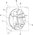
Fig. 1 and 2 each show a schematic view of a filter basket 2 according to the present invention. The filter basket 2 is ideally constructed of metal, but could equally conceivably be made of a plastic material. The filter basket 2 is formed in the lower region 4, for example, from a wire braid 6. In this regard, the length or width dimension of the wire braid 6 is dependent on the size of the filter hose 22 (not shown, see fig. 3-5) such that it is desirably secured or fixed. In the upper region of the filter basket 2, two to six, but ideally three spring elements 11 in the form of spring clips 12 are mounted on the wire braid 6, the spring elements having elastically deformable properties. The spring clip 12 is configured with an at least approximately U-shaped or curved clip end 14. The spring clip 12 is designed such that it can be arranged in the connecting region 17 of the perforated filter plate 16. In this connection, the free end of the clamping end 14 rests on the upper side 18 of the perforated filter plate 16 after the filter basket 2 has been installed. The connecting region 17 has an at least approximately circular recess 19. The filter basket 2 is designed in such a way that the spring clips 12 are adjacent to the edge of the recess 19 of the connecting region 17 with a spacing such that there is sufficient clearance on the connecting region 17 for the installation of the filter hose 22.
In order to position the filter basket 2 in the connecting region 17, a pressure force against the spring clip 12 is required, which is approximately directed in the direction of the middle point of the filter basket and is symbolized by the arrow 20 in fig. 2. The spring clip 12 is pressed into such a way that the spring clip 12 can be introduced into the recess 19 of the connecting region 17. Once the pressure 20 is reduced, the spring clip 12 can move back into its initial position, see the situation shown in fig. 1.
Fig. 3 and 4 each show a schematic illustration of a filter hose 22 according to the invention. The filter hose 22 is made of a flexible filter material and has at the upper end 24 an at least approximately circular circumference corresponding to the connection region 17 of the perforated filter 16, the circumference having a first outer diameter. A snap ring 32 is arranged at the free upper end 24 of the filter hose. The snap ring 32 is elastically deformable to enable installation of the filter hose 22 by a squeezing motion. This requires a high expenditure of force. The diameter of the snap ring 32 is selected such that the filter hose 22 can rest against the inner edge of the recess 19 after being connected to the connecting region 17.
Furthermore, the filter hose 22 has an increased second outer diameter in the region of the upper end 24. The second outer diameter, which is at least slightly larger than the first outer diameter, can be produced, for example, by machining the embedded band 28 into the filter material.
According to the exemplary embodiment shown, two insert strips 26 and 28 are introduced into the material of the filter tube 22 in order to achieve an increased second outer diameter at the imaginary upper end 24 of the filter tube 22 for connection to the perforated filter 16. The embedding strips 26, 28 are spaced apart from one another such that opposite sides of the embedding strips 26, 28 can abut against the upper side 18 and the bottom side 30 of the connecting region 17. A different width of the inlay tapes 26 and 28 is conceivable for this purpose. A better functional surface for mounting the filter tube 22 is achieved by the insert strip 26.
The snap ring 32, which is formed on the upper end 24 of the filter tube 22, is covered at least partially by the two insert strips 26 and 28. In order to provide a better surface for mounting the filter hose 22, a further snap ring 34 can be arranged below the insertion straps 26 and 28, which further snap ring also secures the filter hose 22 in the region of the spring clip 12 (not shown, see fig. 5).
In order to mount the filter hose 22 on a filter device, not shown, the upper end 24 of the filter hose 22 must be deformed, as shown in fig. 4. Only a small force expenditure is required for this, which is indicated by the arrow 36, so that the snap ring 32 and the insert strips 26, 28 are pressed in, so that the upper end 24 of the filter hose 22 can be introduced into the connection region 17. Once the force on snap ring 32 is reduced, the snap ring deforms back to its original shape due to its spring force. A dust-impermeable sealing surface 46 is formed by the circumference of the snap ring 32 and the contact surfaces of the insert strips 26 and 28 on the recess 19 of the connecting region 17.
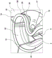
Fig. 5 shows a schematic view of an installed filter hose 22 or an installed filter basket 2 of the fastening system 1. By means of the insert strips 26 and 28 of the filter tube 22, a dust-impermeable sealing surface 46 is formed between the filter tube 22 and the perforated filter 16. The mounting of the filter basket 2 via the clamping end 14 of the spring clamp 12 allows additional stability of the sealing surface 46 between the filter hose 22 and the connection region 16.
For the desired function of the filter device, a venturi element 38 in the form of a venturi nozzle 39 is arranged on the upper face 18 of the connection region 17. The venturi nozzle 39 is connected to a plate section 40 which has a machined flange 44. The venturi nozzle 39 is fixed to the connection region 17 via a plate section 40 by means of a releasable screw connection 42. However, a non-releasable connection of the venturi nozzle 39 is also conceivable according to the invention, for example by a welded connection or a one-piece construction of the venturi nozzle 39 and the filter screen 16 as a pressed part or cast part. The machined flange 44 of the plate section 40 is configured such that the connection of the plate section 40 via the filter hose 22 or the filter basket 2 can be snapped back onto the connection region 17. This shaping achieves additional securing against a vertical pull-out movement of the filter hose 22 or a guidance of the filter basket 2 in the radial direction.
Fig. 6a to 6d depict four installation steps for installing the fastening system 1 according to the invention. In a first installation step shown in fig. 6a, the filter hose 22 is pulled onto the filter basket 2. The filter hose 22 is pulled approximately onto the filter basket 2 to such an extent that the wire braid 6 is covered by the filter hose 22. The snap ring 32 and the second snap ring 34 on the upper end 24 of the filter tube 22, which co-operate with the insert strips 26 and 28, provide a stable active surface on the filter tube 22. Fig. 6b shows a second mounting step. An inwardly directed pressure is applied here against the spring clip 12, so that it can be introduced into the connecting region 17. Due to its spring force, the spring clip 12 moves back into its initial position after the pressure has been removed and rests with the clip end 14 on the upper face 18 of the perforated filter plate 16. In this case, the filter hose 22 is also approximately in the same position, i.e. the filter hose is introduced into this position during the first installation step. In a third step, which is illustrated in fig. 6c, the filter hose 22 is mounted on the connection region 17. In this case, the upper end 24 of the filter hose 22 is deformed in the region of the snap ring 32 such that the cross section of the upper end is smaller than the inner cross section of the recess 19 of the connecting region 17. The upper end 24 of the filter hose 22 is easily accessible due to the distribution of the spring clip 12 on the filter basket 2. The filter hose 22 is positioned in the connecting region 17 in such a way that at least one region with an increased outer diameter is located above the perforated filter 16. Preferably, the filter hose 22 is positioned in the connecting region 17 such that the perforated filter 16 lies between the two insert strips 26 and 28 of the filter hose 22. Thus, a region with an increased outer diameter is arranged above the filter aperture plate 16 and another region with an increased outer diameter is arranged below the filter aperture plate 16. In this case, the clamping end 14 of the spring clamp 12 surrounds the upper insertion band 28 of the filter tube 22. Fig. 6d shows the complete mounting of the fixation system 1. The insert strips 26 and 28 and the snap ring 32 on the upper end 24 of the filter tube 22 form a sealing surface 46 on the recess 19 of the perforated filter 16. Furthermore, the filter basket 2 can be secured to the filter hose 22 by means of the spring clip 12 and its clip end 14.
Fig. 7a to 7c depict three disassembly steps for disassembling the fixation system 1. A first disassembly step is shown in fig. 7 a. In this case, the filter tube 22 is deformed in the region of the snap ring 32 (wherein, according to this embodiment, the two insert strips 26 and 28 are machined into the filter tube 22 in the region of the snap ring 32) in such a way that the cross section of the filter tube is smaller than the area of the inner cross section of the recess 19 of the connecting region 17. The filter hose 22 can thereby be separated from the connection region 17. The upper end 24 of the filter hose 22 is easily accessible due to the distribution of the spring clip 12 on the filter basket 2. In this connection, the spring clips 12 of the filter basket 2 can also be easily deformed. In a second disassembly step, which is illustrated in fig. 7b, an inwardly directed pressure is applied against the spring clamp 12, so that the pressure can be led out of the connection region 17. For this purpose, the filter basket is located approximately at the level of the wire braid 6 of the filter basket 2. In a third installation step, shown in fig. 7c, the filter basket 2 has been released from the perforated filter 16 and the filter hose 22 can be pulled off the filter basket 2.
The same reference numerals are used for the same elements or elements having the same function of the present invention. Furthermore, for the sake of clarity, only the reference numerals necessary for the description of the respective figures are shown in the respective figures. The embodiments shown are merely examples of how a device or method according to the invention can be implemented and these examples are not meant to be limiting in any way.
The invention has been described with reference to the preferred embodiments. It will be appreciated by those skilled in the art that changes and modifications may be made thereto without departing from the invention in its broader aspects.
List of reference numerals
1 fixing system
2 Filter basket
4 lower region
6 wire braid
11 spring element
12 spring clip
14 clamp end
16 filtering pore plate
17 connecting region
18 above
19 recess
20 pressure
22 Filter hose
24 upper end part
26 insert belt
28 insert tape
30 bottom side
32 snap ring
34 clasp
36 force consumption
38 Venturi element
39 Venturi nozzle
40 plate section
42 helical connection
44 flange
46 sealing surface
Claims (12)
1. Fixation system (1) comprising:
-a filter hose (22) having a first outer diameter for filtering dust particles;
-a filter basket (2) for the inner side stabilisation and fixation of the filter hose (22); and
-a connection area (17) arranged on the filter aperture plate (16) for connecting the filter hose (22) and/or the filter basket (2) to the filter device from below the filter aperture plate (16);
-wherein the connection area (17) comprises a recess (19) for the filter hose (22);
-wherein the filter hose (22) has at least one snap ring (32) at one end for connection to the connection region (17);
-wherein the filter hose (22) also has two insert strips (26, 28) spaced apart from each other for connection to the connection region (17);
-wherein the filter hose (22) has a second outer diameter in the region of the embedding band (26, 28), which is at least slightly larger than the first outer diameter of the filter hose (22);
-wherein the filter basket (2) is formed by a basket-like construction having at least two spring elements (11) at its upper end for connection on the connection region (17);
-wherein the snap ring (32) is elastically deformable and can be introduced in at least one first shape having a cross-sectional area smaller than the area of the inner cross-section of the recess (19) of the aperture plate (16);
-wherein below the embedding strip (26, 28) at least one further snap ring (34) is mounted on the filter hose (22) for stabilizing the filter hose (22) in the region of the spring element (11).
2. Fastening system (1) according to claim 1, characterized in that at least two insert strips (26, 28) spaced apart from one another cover at least one snap ring (32) at least partially on the lateral edges.
3. Fastening system (1) according to claim 1, characterized in that the filter hose (22) is connected to the connection region (17) in such a way that two insert strips (26, 28) rest against the upper side (18) and the underside (30) of the filter aperture plate (16), respectively.
4. Fastening system (1) according to claim 2, characterized in that the filter hose (22) is connected to the connection region (17) in such a way that two insert strips (26, 28) rest against the upper side (18) and the underside (30) of the filter aperture plate (16), respectively.
5. Fixing system (1) according to one of claims 1 to 4, characterized in that the two embedding strips (26, 28) bear against the connecting region (17) such that the filter hose (22) cannot execute a vertical movement.
6. A fixation system (1) as claimed in any one of claims 1 to 4, characterized in that the spring element (11) is a spring clip (12), and wherein the filter basket (2) has two to six spring clips (12) at its upper end.
7. A fixing system (1) according to claim 6, characterized in that said filter basket (2) has three spring clips (12) at its upper end.
8. Fixing system (1) according to one of claims 1 to 4, characterized in that a venturi element (38) is mounted on the connection region (17) such that a fastening and/or centering of the filter basket (2) is achieved.
9. Fixing system (1) according to claim 8, characterized in that the venturi element (38) is fixed on the connection region (17) via a flange (44) machined on a plate section (40).
10. Fixing system (1) according to one of claims 1 to 4, characterized in that, for mounting and/or dismounting the filter hose (22) and/or filter basket (2), a pressing movement is carried out against the snap ring (32) and/or spring element (11) in a direction approximately pointing towards the midpoint of the snap ring (32) and/or spring element (11).
11. Method for installing a fixation system (1) according to any one of claims 1 to 10,
-wherein the spring elements (11) of the filter basket (2) are loaded with pressure inwards, guided from below the filter plate (16) up through the recesses (19) of the connection region (17) and hanging into the connection region (17);
-wherein the filter hose (22) is loaded with pressure inwardly in the region of the snap ring (32), the filter hose being guided from below the filter screen (16) up through the recess (19) of the connection region (17);
-wherein the pressure on the snap ring (32) is then removed so that the filter hose (22) abuts against the connection region (17).
12. Method for disassembling a fixation system (1) according to any one of claims 1 to 10,
-wherein the filter hose (22) is pressurized inwardly in the region of the retaining ring (32) and is led out of the connection region (17) from above the filter screen (16) and downwardly through the recess (19) of said connection region; and
-wherein the spring elements (11) of the filter basket (2) are loaded with pressure inwards, from above the filter screen (16) downwards through the recesses (19) of the connection region (17) and out of the connection region.
Applications Claiming Priority (3)
| Application Number | Priority Date | Filing Date | Title |
|---|---|---|---|
| DE102015113127.7 | 2015-08-10 | ||
| DE102015113127.7A DE102015113127A1 (en) | 2015-08-10 | 2015-08-10 | Mounting system and method for mounting or dismounting the fastening system |
| PCT/DE2016/000296 WO2017025075A1 (en) | 2015-08-10 | 2016-07-29 | Securing system and method for assembling or disassembling the securing system |
Publications (2)
| Publication Number | Publication Date |
|---|---|
| CN108136304A CN108136304A (en) | 2018-06-08 |
| CN108136304B true CN108136304B (en) | 2021-05-11 |
Family
ID=56888881
Family Applications (1)
| Application Number | Title | Priority Date | Filing Date |
|---|---|---|---|
| CN201680056612.XA Active CN108136304B (en) | 2015-08-10 | 2016-07-29 | Fastening system and method for mounting and dismounting a fastening system |
Country Status (8)
| Country | Link |
|---|---|
| US (1) | US20180290091A1 (en) |
| EP (1) | EP3334516B1 (en) |
| CN (1) | CN108136304B (en) |
| BR (1) | BR112018002615B1 (en) |
| DE (1) | DE102015113127A1 (en) |
| ES (1) | ES2842177T3 (en) |
| PL (1) | PL3334516T3 (en) |
| WO (1) | WO2017025075A1 (en) |
Families Citing this family (1)
| Publication number | Priority date | Publication date | Assignee | Title |
|---|---|---|---|---|
| DE102018208746B4 (en) | 2018-06-04 | 2020-07-02 | Glatt Gmbh | Filter device arranged on a process apparatus for dedusting process air from the process apparatus |
Family Cites Families (10)
| Publication number | Priority date | Publication date | Assignee | Title |
|---|---|---|---|---|
| DE2551866C3 (en) * | 1975-09-29 | 1980-04-30 | Flex-Kleen Corp., Chicago, Ill. (V.St.A.) | Device for installing bag filter assemblies |
| US4266954A (en) * | 1979-07-12 | 1981-05-12 | The Air Preheater Company, Inc. | Holder for bag filter |
| DE3045759C2 (en) * | 1980-12-04 | 1982-11-18 | BHS-Bayerische Berg-, Hütten- und Salzwerke AG, 8000 München | Bag filter device with compressed air cleaning |
| DE3709365A1 (en) * | 1987-03-21 | 1988-09-29 | Fasse Filter Produktion Gmbh | Filter cloth bag |
| US5061303A (en) * | 1989-07-31 | 1991-10-29 | Pneumafil Corporation | Snap-in filter unit |
| CN2116522U (en) * | 1992-04-22 | 1992-09-23 | 李清华 | Filter-bag carcass |
| US5308369A (en) * | 1993-04-28 | 1994-05-03 | Griffin Environmental Company, Inc. | Snap-in filter bag assembly for bottom loading in dust collector |
| DE20305310U1 (en) | 2002-04-08 | 2004-02-26 | Simatek A/S | Filter basket, for holding filter tube in bag filter, is connected to locking hoop in perforated plate |
| DE10350228B3 (en) * | 2003-10-27 | 2005-08-18 | Intensiv-Filter Gmbh & Co. Kg | dust filter |
| DE102007034533A1 (en) * | 2007-07-24 | 2009-01-29 | Mikropul Gmbh | Filter element for bag filter, has filter tube, where units are provided for fixing and sealing of open top end of filter tube, and radial seals are provided as additional component of unit of filter element |
-
2015
- 2015-08-10 DE DE102015113127.7A patent/DE102015113127A1/en not_active Withdrawn
-
2016
- 2016-07-29 US US15/751,799 patent/US20180290091A1/en not_active Abandoned
- 2016-07-29 WO PCT/DE2016/000296 patent/WO2017025075A1/en active Application Filing
- 2016-07-29 ES ES16762961T patent/ES2842177T3/en active Active
- 2016-07-29 PL PL16762961T patent/PL3334516T3/en unknown
- 2016-07-29 CN CN201680056612.XA patent/CN108136304B/en active Active
- 2016-07-29 BR BR112018002615-8A patent/BR112018002615B1/en active IP Right Grant
- 2016-07-29 EP EP16762961.7A patent/EP3334516B1/en active Active
Also Published As
| Publication number | Publication date |
|---|---|
| BR112018002615A2 (en) | 2018-02-07 |
| PL3334516T3 (en) | 2021-07-19 |
| EP3334516B1 (en) | 2020-10-21 |
| WO2017025075A1 (en) | 2017-02-16 |
| ES2842177T3 (en) | 2021-07-13 |
| BR112018002615B1 (en) | 2022-03-22 |
| US20180290091A1 (en) | 2018-10-11 |
| DE102015113127A1 (en) | 2017-02-16 |
| CN108136304A (en) | 2018-06-08 |
| EP3334516A1 (en) | 2018-06-20 |
Similar Documents
| Publication | Publication Date | Title |
|---|---|---|
| RU2541041C1 (en) | Device for cable fixing at cable output connection | |
| JP5721290B2 (en) | Cable insertion system frame and grommet | |
| CN108136304B (en) | Fastening system and method for mounting and dismounting a fastening system | |
| JPS62168513A (en) | Filter of fuel tank | |
| CN108603556B (en) | Air spring with bellows | |
| KR20180130573A (en) | vent | |
| JP2011255885A (en) | Device for clamping pneumatic pressure and temperature sensor housing onto vehicle rim and housing suitable thereto | |
| US7959804B2 (en) | Use of non-metallic load devices in liquid filters | |
| CN113274804B (en) | End cap assembly, filter and method of use | |
| JP2013258506A (en) | Speaker unit | |
| US20140014662A1 (en) | Transmission vent cap | |
| JP2023060215A (en) | Gasket and sealing structure | |
| CN106823699B (en) | Device for fixing a desiccant cartridge at a housing section of a compressed air preparation device | |
| CN110036228B (en) | Pipe hanger | |
| US20170341005A1 (en) | Filter cartridge | |
| KR20110052856A (en) | Spring pad for vehicle suspension | |
| KR102698794B1 (en) | Filter system | |
| US20120090286A1 (en) | Filter element | |
| EP4039993B1 (en) | Spring nut | |
| FI95829C (en) | Clamping device for floor wells | |
| KR101593775B1 (en) | Fixed structure of bag filter for dust collector | |
| CN112776781A (en) | Neck filter for vehicle brake fluid reservoir | |
| JP3198397U (en) | Fall prevention wire | |
| GB2479894A (en) | Two part ceiling aperture edge protector | |
| CN217887197U (en) | Urea water tank is fixed buckle structure for filter screen |
Legal Events
| Date | Code | Title | Description |
|---|---|---|---|
| PB01 | Publication | ||
| PB01 | Publication | ||
| SE01 | Entry into force of request for substantive examination | ||
| SE01 | Entry into force of request for substantive examination | ||
| GR01 | Patent grant | ||
| GR01 | Patent grant |