CN108024498B - Agricultural liquid application systems, methods and devices - Google Patents
Agricultural liquid application systems, methods and devices Download PDFInfo
- Publication number
- CN108024498B CN108024498B CN201680047266.9A CN201680047266A CN108024498B CN 108024498 B CN108024498 B CN 108024498B CN 201680047266 A CN201680047266 A CN 201680047266A CN 108024498 B CN108024498 B CN 108024498B
- Authority
- CN
- China
- Prior art keywords
- liquid
- seed
- trench
- row unit
- ground engaging
- Prior art date
- Legal status (The legal status is an assumption and is not a legal conclusion. Google has not performed a legal analysis and makes no representation as to the accuracy of the status listed.)
- Active
Links
- 239000007788 liquid Substances 0.000 title claims abstract description 229
- 238000000034 method Methods 0.000 title abstract description 14
- 239000002689 soil Substances 0.000 claims abstract description 141
- 238000009331 sowing Methods 0.000 claims abstract description 21
- 238000010899 nucleation Methods 0.000 claims abstract description 17
- 239000012530 fluid Substances 0.000 claims description 100
- 238000004891 communication Methods 0.000 claims description 75
- 238000002347 injection Methods 0.000 claims description 54
- 239000007924 injection Substances 0.000 claims description 54
- 238000012806 monitoring device Methods 0.000 claims 2
- 239000003337 fertilizer Substances 0.000 abstract description 18
- 238000012544 monitoring process Methods 0.000 abstract description 10
- 238000005259 measurement Methods 0.000 description 31
- 239000000523 sample Substances 0.000 description 15
- 238000002310 reflectometry Methods 0.000 description 14
- 230000003287 optical effect Effects 0.000 description 13
- IJGRMHOSHXDMSA-UHFFFAOYSA-N Atomic nitrogen Chemical compound N#N IJGRMHOSHXDMSA-UHFFFAOYSA-N 0.000 description 12
- 230000008859 change Effects 0.000 description 12
- 239000000463 material Substances 0.000 description 11
- 239000000835 fiber Substances 0.000 description 9
- OKTJSMMVPCPJKN-UHFFFAOYSA-N Carbon Chemical compound [C] OKTJSMMVPCPJKN-UHFFFAOYSA-N 0.000 description 8
- 230000000875 corresponding effect Effects 0.000 description 8
- 229910052751 metal Inorganic materials 0.000 description 8
- 239000002184 metal Substances 0.000 description 8
- RYGMFSIKBFXOCR-UHFFFAOYSA-N Copper Chemical compound [Cu] RYGMFSIKBFXOCR-UHFFFAOYSA-N 0.000 description 7
- 230000009418 agronomic effect Effects 0.000 description 7
- 229910052799 carbon Inorganic materials 0.000 description 7
- 239000011248 coating agent Substances 0.000 description 7
- 238000000576 coating method Methods 0.000 description 7
- 229910052802 copper Inorganic materials 0.000 description 7
- 239000010949 copper Substances 0.000 description 7
- 238000000151 deposition Methods 0.000 description 7
- 239000004033 plastic Substances 0.000 description 7
- 229920003023 plastic Polymers 0.000 description 7
- 239000004020 conductor Substances 0.000 description 6
- 239000000203 mixture Substances 0.000 description 6
- 229910052757 nitrogen Inorganic materials 0.000 description 6
- 238000004140 cleaning Methods 0.000 description 5
- 230000001276 controlling effect Effects 0.000 description 5
- 239000010908 plant waste Substances 0.000 description 5
- -1 polytetrafluoroethylene Polymers 0.000 description 5
- UONOETXJSWQNOL-UHFFFAOYSA-N tungsten carbide Chemical compound [W+]#[C-] UONOETXJSWQNOL-UHFFFAOYSA-N 0.000 description 5
- 238000011144 upstream manufacturing Methods 0.000 description 5
- 229910000831 Steel Inorganic materials 0.000 description 4
- 230000000712 assembly Effects 0.000 description 4
- 238000000429 assembly Methods 0.000 description 4
- 230000014759 maintenance of location Effects 0.000 description 4
- 229910052698 phosphorus Inorganic materials 0.000 description 4
- 238000003825 pressing Methods 0.000 description 4
- 230000008569 process Effects 0.000 description 4
- 238000000926 separation method Methods 0.000 description 4
- 229910001220 stainless steel Inorganic materials 0.000 description 4
- 239000010935 stainless steel Substances 0.000 description 4
- 239000010959 steel Substances 0.000 description 4
- 238000003971 tillage Methods 0.000 description 4
- OAICVXFJPJFONN-UHFFFAOYSA-N Phosphorus Chemical compound [P] OAICVXFJPJFONN-UHFFFAOYSA-N 0.000 description 3
- ZLMJMSJWJFRBEC-UHFFFAOYSA-N Potassium Chemical compound [K] ZLMJMSJWJFRBEC-UHFFFAOYSA-N 0.000 description 3
- 238000010276 construction Methods 0.000 description 3
- 230000006870 function Effects 0.000 description 3
- 230000002209 hydrophobic effect Effects 0.000 description 3
- 238000010191 image analysis Methods 0.000 description 3
- 238000009434 installation Methods 0.000 description 3
- 239000011810 insulating material Substances 0.000 description 3
- 239000005416 organic matter Substances 0.000 description 3
- 239000011574 phosphorus Substances 0.000 description 3
- 229910052700 potassium Inorganic materials 0.000 description 3
- 239000011591 potassium Substances 0.000 description 3
- 239000012255 powdered metal Substances 0.000 description 3
- 238000012545 processing Methods 0.000 description 3
- 230000004044 response Effects 0.000 description 3
- 230000000717 retained effect Effects 0.000 description 3
- 229920004943 Delrin® Polymers 0.000 description 2
- 239000004677 Nylon Substances 0.000 description 2
- 229910001037 White iron Inorganic materials 0.000 description 2
- DHKHKXVYLBGOIT-UHFFFAOYSA-N acetaldehyde Diethyl Acetal Natural products CCOC(C)OCC DHKHKXVYLBGOIT-UHFFFAOYSA-N 0.000 description 2
- 125000002777 acetyl group Chemical class [H]C([H])([H])C(*)=O 0.000 description 2
- 238000009529 body temperature measurement Methods 0.000 description 2
- 230000001413 cellular effect Effects 0.000 description 2
- 238000005056 compaction Methods 0.000 description 2
- 230000002596 correlated effect Effects 0.000 description 2
- 238000005520 cutting process Methods 0.000 description 2
- 230000008021 deposition Effects 0.000 description 2
- 238000001514 detection method Methods 0.000 description 2
- 239000000428 dust Substances 0.000 description 2
- 230000007246 mechanism Effects 0.000 description 2
- 229920001778 nylon Polymers 0.000 description 2
- 239000000575 pesticide Substances 0.000 description 2
- 229920000642 polymer Polymers 0.000 description 2
- 230000003014 reinforcing effect Effects 0.000 description 2
- 239000011435 rock Substances 0.000 description 2
- 238000007789 sealing Methods 0.000 description 2
- 230000000087 stabilizing effect Effects 0.000 description 2
- 210000002105 tongue Anatomy 0.000 description 2
- 241000405070 Percophidae Species 0.000 description 1
- 239000004696 Poly ether ether ketone Substances 0.000 description 1
- 239000004698 Polyethylene Substances 0.000 description 1
- 239000004743 Polypropylene Substances 0.000 description 1
- 239000004793 Polystyrene Substances 0.000 description 1
- 239000004809 Teflon Substances 0.000 description 1
- 229920006362 Teflon® Polymers 0.000 description 1
- 238000009825 accumulation Methods 0.000 description 1
- 230000009471 action Effects 0.000 description 1
- 230000004913 activation Effects 0.000 description 1
- 239000000853 adhesive Substances 0.000 description 1
- 230000001070 adhesive effect Effects 0.000 description 1
- 229910052782 aluminium Inorganic materials 0.000 description 1
- XAGFODPZIPBFFR-UHFFFAOYSA-N aluminium Chemical compound [Al] XAGFODPZIPBFFR-UHFFFAOYSA-N 0.000 description 1
- 238000013459 approach Methods 0.000 description 1
- 230000008901 benefit Effects 0.000 description 1
- 238000005219 brazing Methods 0.000 description 1
- 238000006243 chemical reaction Methods 0.000 description 1
- 239000010941 cobalt Substances 0.000 description 1
- 229910017052 cobalt Inorganic materials 0.000 description 1
- GUTLYIVDDKVIGB-UHFFFAOYSA-N cobalt atom Chemical compound [Co] GUTLYIVDDKVIGB-UHFFFAOYSA-N 0.000 description 1
- 239000003086 colorant Substances 0.000 description 1
- 150000001875 compounds Chemical class 0.000 description 1
- 230000006835 compression Effects 0.000 description 1
- 238000007906 compression Methods 0.000 description 1
- 238000007596 consolidation process Methods 0.000 description 1
- 238000011109 contamination Methods 0.000 description 1
- 230000009849 deactivation Effects 0.000 description 1
- 230000003247 decreasing effect Effects 0.000 description 1
- 230000002939 deleterious effect Effects 0.000 description 1
- 230000000881 depressing effect Effects 0.000 description 1
- 238000013461 design Methods 0.000 description 1
- 238000010586 diagram Methods 0.000 description 1
- 238000006073 displacement reaction Methods 0.000 description 1
- 230000000694 effects Effects 0.000 description 1
- 239000012777 electrically insulating material Substances 0.000 description 1
- 210000003414 extremity Anatomy 0.000 description 1
- 238000001125 extrusion Methods 0.000 description 1
- 238000009313 farming Methods 0.000 description 1
- 210000003608 fece Anatomy 0.000 description 1
- 230000004720 fertilization Effects 0.000 description 1
- 229910002804 graphite Inorganic materials 0.000 description 1
- 239000010439 graphite Substances 0.000 description 1
- 230000005484 gravity Effects 0.000 description 1
- 239000004009 herbicide Substances 0.000 description 1
- 239000003999 initiator Substances 0.000 description 1
- 239000010871 livestock manure Substances 0.000 description 1
- 238000004519 manufacturing process Methods 0.000 description 1
- 238000012986 modification Methods 0.000 description 1
- 230000004048 modification Effects 0.000 description 1
- 238000000465 moulding Methods 0.000 description 1
- 239000000618 nitrogen fertilizer Substances 0.000 description 1
- QJGQUHMNIGDVPM-UHFFFAOYSA-N nitrogen group Chemical group [N] QJGQUHMNIGDVPM-UHFFFAOYSA-N 0.000 description 1
- 239000013307 optical fiber Substances 0.000 description 1
- 229920002530 polyetherether ketone Polymers 0.000 description 1
- 229920000573 polyethylene Polymers 0.000 description 1
- 229920001155 polypropylene Polymers 0.000 description 1
- 229920002223 polystyrene Polymers 0.000 description 1
- 229920001343 polytetrafluoroethylene Polymers 0.000 description 1
- 239000004810 polytetrafluoroethylene Substances 0.000 description 1
- 239000004800 polyvinyl chloride Substances 0.000 description 1
- 229920000915 polyvinyl chloride Polymers 0.000 description 1
- 238000004382 potting Methods 0.000 description 1
- 230000002787 reinforcement Effects 0.000 description 1
- 238000010079 rubber tapping Methods 0.000 description 1
- 229910052594 sapphire Inorganic materials 0.000 description 1
- 239000010980 sapphire Substances 0.000 description 1
- 229920002545 silicone oil Polymers 0.000 description 1
- 239000004016 soil organic matter Substances 0.000 description 1
- 239000000243 solution Substances 0.000 description 1
- 238000005507 spraying Methods 0.000 description 1
- 238000003860 storage Methods 0.000 description 1
- 239000010902 straw Substances 0.000 description 1
- 210000003813 thumb Anatomy 0.000 description 1
- 238000012546 transfer Methods 0.000 description 1
- 239000012780 transparent material Substances 0.000 description 1
- 238000003466 welding Methods 0.000 description 1
Images


Classifications
-
- A—HUMAN NECESSITIES
- A01—AGRICULTURE; FORESTRY; ANIMAL HUSBANDRY; HUNTING; TRAPPING; FISHING
- A01C—PLANTING; SOWING; FERTILISING
- A01C7/00—Sowing
- A01C7/06—Seeders combined with fertilising apparatus
-
- A—HUMAN NECESSITIES
- A01—AGRICULTURE; FORESTRY; ANIMAL HUSBANDRY; HUNTING; TRAPPING; FISHING
- A01B—SOIL WORKING IN AGRICULTURE OR FORESTRY; PARTS, DETAILS, OR ACCESSORIES OF AGRICULTURAL MACHINES OR IMPLEMENTS, IN GENERAL
- A01B49/00—Combined machines
- A01B49/04—Combinations of soil-working tools with non-soil-working tools, e.g. planting tools
- A01B49/06—Combinations of soil-working tools with non-soil-working tools, e.g. planting tools for sowing or fertilising
-
- A—HUMAN NECESSITIES
- A01—AGRICULTURE; FORESTRY; ANIMAL HUSBANDRY; HUNTING; TRAPPING; FISHING
- A01B—SOIL WORKING IN AGRICULTURE OR FORESTRY; PARTS, DETAILS, OR ACCESSORIES OF AGRICULTURAL MACHINES OR IMPLEMENTS, IN GENERAL
- A01B79/00—Methods for working soil
- A01B79/005—Precision agriculture
-
- A—HUMAN NECESSITIES
- A01—AGRICULTURE; FORESTRY; ANIMAL HUSBANDRY; HUNTING; TRAPPING; FISHING
- A01C—PLANTING; SOWING; FERTILISING
- A01C21/00—Methods of fertilising, sowing or planting
- A01C21/005—Following a specific plan, e.g. pattern
-
- A—HUMAN NECESSITIES
- A01—AGRICULTURE; FORESTRY; ANIMAL HUSBANDRY; HUNTING; TRAPPING; FISHING
- A01C—PLANTING; SOWING; FERTILISING
- A01C21/00—Methods of fertilising, sowing or planting
- A01C21/007—Determining fertilization requirements
-
- A—HUMAN NECESSITIES
- A01—AGRICULTURE; FORESTRY; ANIMAL HUSBANDRY; HUNTING; TRAPPING; FISHING
- A01C—PLANTING; SOWING; FERTILISING
- A01C23/00—Distributing devices specially adapted for liquid manure or other fertilising liquid, including ammonia, e.g. transport tanks or sprinkling wagons
- A01C23/02—Special arrangements for delivering the liquid directly into the soil
- A01C23/023—Special arrangements for delivering the liquid directly into the soil for liquid or gas fertilisers
- A01C23/025—Continuous injection tools
-
- A—HUMAN NECESSITIES
- A01—AGRICULTURE; FORESTRY; ANIMAL HUSBANDRY; HUNTING; TRAPPING; FISHING
- A01C—PLANTING; SOWING; FERTILISING
- A01C5/00—Making or covering furrows or holes for sowing, planting or manuring
- A01C5/06—Machines for making or covering drills or furrows for sowing or planting
- A01C5/066—Devices for covering drills or furrows
- A01C5/068—Furrow packing devices, e.g. press wheels
-
- A—HUMAN NECESSITIES
- A01—AGRICULTURE; FORESTRY; ANIMAL HUSBANDRY; HUNTING; TRAPPING; FISHING
- A01C—PLANTING; SOWING; FERTILISING
- A01C7/00—Sowing
- A01C7/08—Broadcast seeders; Seeders depositing seeds in rows
- A01C7/10—Devices for adjusting the seed-box ; Regulation of machines for depositing quantities at intervals
- A01C7/102—Regulating or controlling the seed rate
- A01C7/105—Seed sensors
-
- A—HUMAN NECESSITIES
- A01—AGRICULTURE; FORESTRY; ANIMAL HUSBANDRY; HUNTING; TRAPPING; FISHING
- A01C—PLANTING; SOWING; FERTILISING
- A01C7/00—Sowing
- A01C7/20—Parts of seeders for conducting and depositing seed
- A01C7/201—Mounting of the seeding tools
- A01C7/203—Mounting of the seeding tools comprising depth regulation means
-
- G—PHYSICS
- G01—MEASURING; TESTING
- G01N—INVESTIGATING OR ANALYSING MATERIALS BY DETERMINING THEIR CHEMICAL OR PHYSICAL PROPERTIES
- G01N21/00—Investigating or analysing materials by the use of optical means, i.e. using sub-millimetre waves, infrared, visible or ultraviolet light
- G01N21/17—Systems in which incident light is modified in accordance with the properties of the material investigated
- G01N21/25—Colour; Spectral properties, i.e. comparison of effect of material on the light at two or more different wavelengths or wavelength bands
- G01N21/31—Investigating relative effect of material at wavelengths characteristic of specific elements or molecules, e.g. atomic absorption spectrometry
- G01N21/35—Investigating relative effect of material at wavelengths characteristic of specific elements or molecules, e.g. atomic absorption spectrometry using infrared light
- G01N21/3554—Investigating relative effect of material at wavelengths characteristic of specific elements or molecules, e.g. atomic absorption spectrometry using infrared light for determining moisture content
-
- G—PHYSICS
- G01—MEASURING; TESTING
- G01N—INVESTIGATING OR ANALYSING MATERIALS BY DETERMINING THEIR CHEMICAL OR PHYSICAL PROPERTIES
- G01N21/00—Investigating or analysing materials by the use of optical means, i.e. using sub-millimetre waves, infrared, visible or ultraviolet light
- G01N21/17—Systems in which incident light is modified in accordance with the properties of the material investigated
- G01N21/47—Scattering, i.e. diffuse reflection
- G01N21/4738—Diffuse reflection, e.g. also for testing fluids, fibrous materials
-
- G—PHYSICS
- G01—MEASURING; TESTING
- G01N—INVESTIGATING OR ANALYSING MATERIALS BY DETERMINING THEIR CHEMICAL OR PHYSICAL PROPERTIES
- G01N33/00—Investigating or analysing materials by specific methods not covered by groups G01N1/00 - G01N31/00
- G01N33/24—Earth materials
- G01N33/246—Earth materials for water content
-
- G—PHYSICS
- G06—COMPUTING; CALCULATING OR COUNTING
- G06F—ELECTRIC DIGITAL DATA PROCESSING
- G06F17/00—Digital computing or data processing equipment or methods, specially adapted for specific functions
- G06F17/10—Complex mathematical operations
- G06F17/18—Complex mathematical operations for evaluating statistical data, e.g. average values, frequency distributions, probability functions, regression analysis
-
- G—PHYSICS
- G01—MEASURING; TESTING
- G01N—INVESTIGATING OR ANALYSING MATERIALS BY DETERMINING THEIR CHEMICAL OR PHYSICAL PROPERTIES
- G01N33/00—Investigating or analysing materials by specific methods not covered by groups G01N1/00 - G01N31/00
- G01N33/24—Earth materials
- G01N2033/245—Earth materials for agricultural purposes
Abstract
Systems, methods, and devices for monitoring soil properties and applying fertilizer during a seeding operation. Various sensors are provided in the ground engaging members for monitoring soil properties. The ground engaging members may have a configuration that opens side furrows in the sidewalls of the sowing furrow and may include liquid application conduits for injecting liquid into the formed side furrows.
Description
Background
In recent years, with the use of advanced location specific agricultural application and measurement systems (used in so-called "fine farming" practice), there has been an increase in the number of seeders: the spatial variation of the soil properties is determined and, in view of these variations, the input application variables (e.g. the depth of sowing) and the application of fertilizers and other liquids are varied at the appropriate location during the sowing operation. However, currently available mechanisms for measuring soil properties do not operate locally effectively throughout the process or at the same time as the input operation (e.g., seeding). In addition, commercial solutions for applying liquids include applying the liquid on top of the seeds in the seed trench, which can result in deleterious effects such as "burning out" (i.e., over-fertilizing) the seeds. Other liquid application schemes include making individual trenches in the soil surface (between the sowing trenches made in the row unit) and depositing the liquid in individual vertical trenches, which may result in inefficient use of the applied fertilizer.
Accordingly, there is a need in the art for a method for monitoring soil properties during agricultural input applications and for the efficient application of liquids during sowing operations.
Drawings
Fig.1 is a top view of one embodiment of an agricultural planter.
Fig.2 is a side view of one embodiment of a planter row unit.
FIG.3 schematically illustrates one embodiment of a soil monitoring system.
FIG.4A is a side view of an embodiment of a seed compactor equipped with multiple compactor sensors, shown mounted in a row unit and positioned in a seed trench.
Fig.4B is a top view of the seed press of fig. 4A.
Fig.4C is a rear view of the seed press of fig. 4A.
FIG.5 is a side view of another embodiment of a seed press equipped with a plurality of seed press sensors.
Fig.6 is a cross-sectional view taken along line D-D of fig. 5.
Fig.7 is a cross-sectional view E-E of fig. 5.
Fig.8 is a sectional view F-F of fig. 5.
Fig.9 is a G-G sectional view of fig. 5.
Fig.10 is a partial cross-sectional side view of the press of fig. 5.
Fig.11 is a view along direction a of fig. 10.
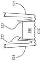
Fig.12 is a sectional view taken along line B-B of fig. 10.
Fig.13 is a cross-sectional view of fig.10 taken along line C-C.
Fig.14 is an enlarged partial cross-sectional view of the tamp of fig. 5.
Fig.15 is a rear view of another embodiment of the seeder shown in the seed trench.
FIG.16 is a rear view of yet another embodiment of the seeder shown in the seed trench.
Fig.17 is a graph of reflectance sensor signals.
FIG.18 is a side view of one embodiment of a reference sensor.
FIG.19A is a side view of one embodiment of an instrumented indenter containing a fiber optic cable that transmits light to a reflectance sensor.
Figure 19B is a side view of one embodiment of an instrumented indenter containing a fiber optic cable that transmits light to a spectrometer.
Fig. 20A-20B illustrate an embodiment of a soil data display screen.
21A-21B illustrate embodiments of the spatial map screen.
Fig.22 shows one embodiment of a seeding data display screen.
FIG.23 is a side view of another embodiment of a reference sensor with an instrumented handle.
Fig.24 is a front view of the reference sensor of fig. 23.
FIG.25 is a side view of another embodiment of a seed press.
Fig.26 is a cross-sectional side view of the tamp of fig. 25.
FIG.27 is a side view of a seed press with a lateral groove-engaging extrusion.
Fig.28 is a rear view of the seed press of fig. 27.
FIG.29 is a side view of a remote trench feature sensing system.
FIG.30 is a side view of another embodiment of a forcer mounted to a mounting bracket.
Fig.31 is a perspective view of another embodiment of a seed press.
FIG.32 is a side view of the crimper of FIG.31 with its wing body and manifold removed.
Fig.33 is a side view of the press of fig. 31.
FIG.34 is a perspective view of the wing body and manifold of the press of FIG. 31.
Fig.35 is a rear view of the seed press of fig. 31.
Fig.36 is a cross-sectional view a-a of fig.33 of the press of fig. 31.
FIG.37 schematically illustrates another embodiment of a soil monitoring system.
Fig.38 is a side view of an embodiment of a seed press and schematically illustrates an application control system.
Fig.39 is a partial top view of the tamp of fig. 38.
FIG.40 is a side view of one embodiment of a liquid application assembly.
Fig.41 is a front view of the liquid application assembly of fig. 40.
FIG.42 is a side elevational view of the liquid application assembly of FIG.40 with the side furrow opener removed.
FIG.43 is a side view of another embodiment of a liquid application assembly.
FIG.44 is a side view of one embodiment of a liquid application assembly cooperating with a row unit sub-frame.
FIG.45 is a side view of the liquid application assembly of FIG.44 with certain components cut away and/or not shown for clarity.
FIG.46 is a perspective view of the liquid application assembly of FIG.44 with certain components cut away and/or not shown for clarity and with its wing bodies shown in phantom.
FIG.47 schematically illustrates one embodiment of a fluid control system.
Fig.48 is a side view of a flow balancing valve in fluid communication with a first liquid inlet and a second liquid inlet.
FIG.49 is a perspective view of the manifold showing the liquid passage therethrough.
FIG.50A is a perspective view of one embodiment of a resilient self-opening valve.
FIGS. 50B-50C are cross-sectional views of the manifold along the cross-section X-X of FIG.49 showing another embodiment of a self-opening valve.
FIG.51 illustrates an embodiment of an image capture device for a row unit.
FIG.52 illustrates one embodiment of a graphical display displaying an image captured by the image capture device of FIG. 51.
FIG.53 illustrates one embodiment of a row selection process.
Detailed Description
Depth control and soil monitoring system
Referring now to the drawings, wherein like reference numerals designate identical or corresponding parts throughout the several views, fig.1 illustrates a tractor 5, the tractor 5 towing an agricultural implement, such as a planter 10, which includes a toolbar 14 operable to support a plurality of row units 200. Preferably, implement monitor 50 is located in the cab of tractor 5, and implement monitor 50 preferably includes a central processing unit ("CPU"), memory, and a graphical user interface ("GUI") (e.g., a touch screen interface). Preferably, a global positioning system ("GPS") receiver 52 is mounted to the tractor 5.
Turning to fig.2, one embodiment of a row unit 200 is shown as a planter row unit. Preferably, the row unit 200 is pivotally connected to the toolbar 14 by parallel links 216. Preferably, the actuator 218 is arranged to exert a lifting force and/or a depressing force on the row unit 200. Preferably, the solenoid valve 390 is in fluid communication with the actuator 218 for varying the lift and/or down force applied by the actuator. Preferably, the trenching system 234 comprises two trenching disks 244, the trenching disks 244 being rollingly mounted to a downwardly extending shank 254 and configured to open a V-shaped trench 38 in the soil 40. A pair of metrology wheels 248 are pivotally supported by a pair of corresponding metrology wheel arms 260. The height of the metering wheel 248 relative to the trenching disc 244 sets the depth of the trench 38. The depth adjustment rocker 268 limits the upward travel of the metrology wheel arm 260 and thus the metrology wheel 248. Preferably, a depth adjustment actuator 380 is also provided for changing the position of the depth adjustment rocker 268 and thereby the height of the metrology wheel 248. Preferably, the actuator 380 is a linear actuator mounted to the row unit 200 and pivotally coupled to the upper end of the rocker 268. In some embodiments, the depth adjustment actuator 380 comprises a device such as disclosed in international patent application No. PCT/US2012/035585 ("the 585 application"), the disclosure of which is incorporated herein by reference. Preferably, an encoder 382 is also provided for generating a signal related to the linear extension of the actuator 380. It will be appreciated that the linear extension of the actuator 380 is related to the depth of the groove 38 when the metrology wheel arm 260 is in contact with the rocker 268. Preferably, a downforce sensor 392 is provided for generating a signal related to the amount of force exerted by the metrology wheel 248 on the soil 40; in some embodiments, downforce sensor 392 comprises an instrumented pin about which rocker 268 is pivotally coupled to row unit 200. The instrumented pins can be instrumented pins such as those disclosed in applicant's U.S. patent application No.12/522,253, the disclosure of which is incorporated herein by reference.
With continued reference to fig.2, a seed meter 230 is also preferably provided for depositing seeds 42 from hopper 226 into trench 38. Seed meter 230 as described herein may be a seed meter as disclosed in applicant's international patent application PCT/US2012/030,192, the disclosure of which is incorporated herein by reference. For example, seeds 42 from hopper 226 are deposited into trench 38 by providing seed feed tube 232. In some embodiments, instead of using seed tube 232, a seed feeder delivers seeds at a controlled rate from the seed meter to the furrow, such as U.S. patent application No.14/347,902 and/or U.S. patent No.8,789,482, the disclosures of both of which are incorporated herein by reference. In these embodiments, a bracket as shown in FIG.30 is preferably provided for mounting the seed press to the handle 254 through a sidewall extending laterally around the seed transporter, such that the seed press is disposed behind the seed transporter for pressing the seed into the soil after the seed transporter has deposited the seed. In some embodiments, the seed meter is powered by an electric drive 315, the electric drive 315 being used to drive a seed disk within the seed meter. In other embodiments, the drive 315 may comprise a hydraulic drive for driving the seed puck. A seed sensor 305 (e.g., an optical or electromagnetic seed sensor for generating a signal indicative of whether the seed passes or not) is preferably mounted to the seed tube 232 and is configured to transmit light or electromagnetic waves in the path of the seed 42. The gutter-closing system 236 includes one or more gutter-closing wheels 238 pivotably coupled to the row unit 200 and for closing the gutter 38.
Turning to fig.3, a depth control and soil monitoring system 300 is shown. Preferably, monitor 50 is in data communication with components associated with each row unit 200, including driver 315, seed sensor 305, GPS receiver 52, down pressure sensor 392, down pressure valve 390, depth adjustment actuator 380 and depth actuator encoder 382. In some embodiments, particularly those in which each seed meter 230 is not driven by a separate drive 315, monitor 50 is also preferably in data communication with a clutch 310, which clutch 310 is used to selectively operatively couple seed meter 230 to drive 315.
With continued reference to fig.3, preferably, the monitor 50 is in data communication with the cellular modem 330 such that the monitor 50 can be in data communication with the internet 335, or the monitor 50 is in data communication with other components for enabling the monitor 50 to be in data communication with the internet 335. The internet connection may comprise a wireless connection or a cellular connection. Preferably, monitor 50 receives data from meteorological data server 340 and soil data server 345 via an internet connection. Preferably, the monitor 50 sends measurement data (e.g., measurements described herein) to a recommendation server (which may be the same server as the meteorological data server 340 and/or the soil data server 345) for storage via an Internet connection, and receives agricultural recommendations (e.g., seeding recommendations including, for example, seeding depth, whether to seed, in which fields to seed, which seeds to seed, or which crops to seed) from a recommendation system stored on the server. In some embodiments, the recommendation system updates seed recommendations based on measurement data provided by the monitor 50.
With continued reference to fig.3, preferably, monitor 50 is also in data communication with one or more temperature sensors 360, temperature sensors 360 being mounted to planter 10 for generating signals related to the temperature of soil being processed by planter row units 200. Preferably, monitor 50 is in data communication with one or more reflectance sensors 350, reflectance sensors 350 being mounted to planter 10 for generating signals related to the reflectance of soil being processed by planter row units 200.
Referring to fig.3, monitor 50 is preferably in data communication with one or more conductivity sensors 370, conductivity sensors 370 being mounted to planter 10 for generating signals related to the conductivity of the soil being processed by planter row units 200.
In some embodiments, a first set of reflectance sensors 350, temperature sensors 360 and conductivity sensors 370 are mounted to the indenter 400 for measuring reflectance, temperature and conductivity, respectively, of the soil in the trench 38. In some embodiments, a second set of reflectance sensors 350, temperature sensors 360 and conductivity sensors 370 are mounted to the reference sensor assembly 1800 for measuring reflectance, temperature and conductivity, respectively, of the soil, preferably at a depth different from the depth of the sensors on the indenter 400.
In some embodiments, the sensor subsets are in data communication with the monitor 50 via a bus 60 (e.g., a CAN bus). In some embodiments, the sensor and reference sensor assembly 1800 mounted to the piezo 400 is also in data communication with the monitor 50 via the bus 60. However, in the embodiment shown in FIG.3, the transducer mounted to the tamp body 400, and the reference transducer assembly 1800 are in data communication with the monitor 50 via first and second wireless transmitters 62-1 and 62-2, respectively. The wireless transmitter 62 at each row unit is preferably in data communication with a single wireless receiver 64, which wireless receiver 64 is in turn in data communication with the monitor 50. The wireless receiver may be mounted to the toolbar 14 or the cab of the tractor 5.
Soil monitoring, seed monitoring and seed pressing device
Turning to fig. 4A-4C, an embodiment of a seeder 400 is shown, the seeder 400 having a plurality of sensors for sensing soil characteristics. Preferably, the tamp 400 includes a flexible portion 410, the flexible portion 410 being mounted to the stem 254 and/or the seed tube 232 by a bracket 415. In some embodiments, holder 415 is similar to one of the holder embodiments disclosed in U.S. patent No.6,918,342, the disclosure of which is incorporated herein by reference. Preferably, the seed press includes a press body 490 for being at least partially received within the V-shaped groove 38 and for pressing the seed 42 to the bottom of the groove. The flexible portion 410 preferably urges the indenter body 490 into resilient engagement with the trench when the indenter 400 is lowered into the trench 38. In some embodiments, flexible portion 410 preferably includes external or internal reinforcements, as disclosed in international patent application PCT/US2013/066652, the disclosures of which are incorporated herein by reference. In some embodiments, the forcer body 490 includes a removable portion 492, preferably, the removable portion 492 is slid into locking engagement with the remainder of the forcer body. The forcer body 490 (preferably including the portion of the forcer body that engages the soil, which in some embodiments includes the removable portion 492) is preferably made of a material having a hydrophobic and/or anti-stick property (or having a hydrophobic and/or anti-stick outer surface or coating), for example, a polytetrafluoroethylene graphite coating and/or a polymer including a hydrophobic material (e.g., silicone oil or polyetheretherketone) impregnated therein.
Referring to fig.30, a variation of the seed tamp assembly is shown, the seed tamp assembly 3000 mounted to a tamp holder 4000. Preferably, the seeder support 4000 is for mounting to the handle 254 of a row unit and supporting the seeder 3000 in a rear position of the seed tube 232 or seed feeder of the row unit. Preferably, the indenter 3000 includes an indenter body 3090, the indenter body 3090 being resiliently biased to the bottom of the trench 38 by a flexible portion 3050. Preferably, the seed indenter 3000 includes an upper portion 3070, the upper portion 3070 being received in an opening 4080 of the indenter bracket 4000. Preferably, the tamp 3000 includes a hook 3015, the hook 3015 engaging the wall 4015 of the support. It will be appreciated that the engagement of the wall and hook prevents the seed indenter from moving up, forward or backward relative to the bracket, but allows the seed indenter to slide down relative to the bracket. Preferably, the tamp 3000 includes a flexible mounting portion 3060, the flexible mounting portion 3060 having an angled portion 3065 at a lower end thereof and a rearward facing retention tab 3020. During installation, the user preferably grasps the flexible portion 3050 and inserts the upper portion 3070 into the opening 4080. Preferably, the tamp is sized such that when the tamp is inserted into the holder, the flexible mounting portion 3060 deflects towards the flexible portion 3050 until the retention tab 3020 reaches the opening 4020 in the rear of the holder, allowing the flexible mounting portion 3060 to return to a relaxed (or more relaxed) state in which the retention tab 3020 engages the opening 4020 to prevent the tamp 3000 from sliding downward relative to the holder 4000. In a preferred embodiment, wall 4015 and opening 4020 are preferably arranged such that retaining tab 3020 engages opening 4020 when the tamp reaches a position where hook 3015 engages wall 4015, thereby preventing upward or downward movement of the tamp with respect to the support after assembly is complete. During removal of the indenter 3000, the user preferably grasps the flexible portion 3050 and presses the angled portion 3065 (e.g., with a thumb) causing the flexible mounting portion 3060 to deflect toward the flexible portion 3050, thereby withdrawing the retention tab 3020 from the opening 4020 and allowing the user to lower the indenter and remove the indenter from the bracket. It will be appreciated that if dust or residue enters the opening 4080 from above the upper portion 3070 of the press, it will fall downwardly through the gap 3080 between the flexible portion 3050 and the mounting portion 3060 so that it does not become lodged in the stand or press during operation.
With continued reference to fig.30, the liquid applicator tube may be retained on the press device 3000 such that the distal end of the liquid applicator tube (which may include a diverter or other structural feature) is retained at the rear end of the press device, thereby enabling the liquid applicator tube to be used to dispense liquid behind the press device. In the embodiment shown in fig.30, the upper portion 3070 of the indenter 3000 includes an opening 3072, the opening 3072 being sized to receive the liquid applicator tube 3171; the flexible portion 3050 comprises a hook 3052, the hook 3052 sized to releasably retain a liquid application tube; and the seeder body 3090 includes an internal channel 3092, the internal channel 3092 being sized to receive the liquid applicator tube 3171.
With continued reference to fig.30, the forcer 3000 may be provided with any of the forcer sensors described herein. In such embodiments, the bracket 4000 includes mounting tabs 4010 for supporting a housing (not shown) provided with electronics or lead-throughs for transmitting and processing data generated by the piezo sensor.
Returning to fig. 4A-4C, preferably, the indenter 400 includes a plurality of reflectance sensors 350a, 350 b. Preferably, each reflectance sensor 350 is used to measure the reflectance of the soil. In a preferred embodiment, the reflectance sensor 350 is used to measure soil in the trench 38, preferably at the bottom of the trench. Preferably, the reflectance sensor 350 includes a lens disposed at the bottom of the indenter body 490 for engaging the soil at the bottom of the trench 38. In some embodiments, the reflectance sensor 350 comprises one of the embodiments disclosed in U.S. patent No.8,204,689 and/or U.S. provisional patent application No.61/824,975, both of which are incorporated herein by reference. In various embodiments, the reflectance sensor 350 is used to measure reflectance in the visible range (e.g., 400 and/or 600 nanometers), near infrared range (e.g., 940 nanometers), and/or other infrared ranges.
Preferably, the seeder 400 is provided with the temperature sensor 360. Preferably, a temperature sensor 360 is provided for measuring the temperature of the soil; in a preferred embodiment, the temperature sensor is used to measure soil in trench 38, preferably at or near the bottom of trench 38. Preferably, the temperature sensor 360 includes soil engaging tabs 364, 366 (fig. 4B, 4C), the soil engaging tabs 364, 366 being for slidingly engaging each side of the furrow 38 as the planter traverses the field. Preferably, the tabs 364, 366 engage the channel 38 at or near the bottom of the channel 38. Preferably, the tabs 364, 366 are made of a thermally conductive material such as copper. Preferably, the tabs 364 are secured to and in thermal communication with the central portion 362 contained within the indenter body 490. Preferably, the central portion 362 comprises a thermally conductive material such as copper. In some embodiments, the central portion 362 comprises a hollow copper rod. Preferably, the center portion 362 is in thermal communication with a thermocouple secured to the center portion. In other embodiments, temperature sensor 360 may include a non-contact temperature sensor, such as an infrared thermometer. In some embodiments, other measurements made by system 300 (e.g., reflectance measurements, conductivity measurements, and/or measurements derived from these measurements) are temperature compensated by temperature measurements made by temperature sensor 360. The adjustment of the temperature-based temperature-compensated measurement is preferably accomplished by consulting an empirical look-up table correlating temperature compensation values to soil temperature. For example, reflectance measurements at near infrared wavelengths may increase (in some embodiments, decrease) by 1% every 1 degree celsius when the soil temperature exceeds 10 degrees celsius.
Preferably, the press includes a plurality of conductivity sensors 370, as shown in fig. 4A-4C, the conductivity sensors 370 may be suffixed with "f" and "r" after identification to designate forward and backward sensors, respectively. This use of the suffixes "f" and "r" will continue to be used hereinafter to identify other forward and backward sensors. Preferably, each conductivity sensor 370 is provided and used to measure the conductivity of the soil. In a preferred embodiment, conductivity sensor 370 is used to measure the sudden conductivity within trench 38, preferably the conductivity of the soil at or near the bottom of trench 38. Preferably, conductivity sensor 370 includes soil engagement tabs 374, 376, soil engagement tabs 374, 376 for slidingly engaging each side of furrow 38 as the planter traverses the field. Preferably, the ear panels 374, 376 engage the channel 38 at or near the bottom of the channel. Preferably, the tabs 374, 376 are made of a conductive material such as copper. Preferably, the tabs 374 are secured to and in electrical communication with a central portion 372 that is receivable within the indenter body 490. Preferably, the central portion 372 comprises a conductive material such as copper. In some embodiments, the central portion 372 comprises a copper rod. Preferably, the central portion 372 is in electrical communication with electrical leads secured to the central portion.
In some embodiments, the indenter 400 cooperates with the system 300 to measure the conductivity of the soil adjacent the trench 38 by measuring the electrical potential between the forward conductivity sensor 370f and the rearward conductivity sensor 370 f. In other embodiments, conductivity sensors 370f, 370r may be disposed in longitudinally spaced relation at the bottom of the seeder to measure the conductivity at the bottom of the seed trench.
In other embodiments, conductivity sensor 370 may include one or more ground working or ground contacting devices (e.g., discs or handles) that contact the soil and are preferably electrically isolated from each other or from another reference voltage. Preferably, the voltage potential between the sensors 370 or other reference voltages is measured by the system 300. Preferably, the voltage potential or another conductivity value derived from the voltage potential is reported to the operator. Conductivity values can also be correlated with the location of the GPS report for generating a spatially varying map of conductivity across the field. In such embodiments, the conductivity sensor may comprise one or more trench disks of the planter row units, row cleaner wheels of the planter row units, a ground contact handle of the planter, a ground contact shoe suspended from the handle of the planter, a handle of a tillage tool, or a disk of a tillage tool. In some embodiments, the first conductivity sensor may comprise a component of a first agricultural row unit (e.g., a disk or handle) and the second conductivity sensor comprises a component of a second agricultural row unit (e.g., a disk or handle), such that the conductivity of soil extending laterally between the first and second row units may be measured. It should be understood that at least one conductivity sensor described herein is preferably electrically isolated from another sensor or reference voltage. In one example, a conductivity sensor is mounted to an implement (e.g., a planter row unit or a tillage tool) by: the conductivity sensor is first mounted to an electrically insulating member (e.g., a member made of an electrically insulating material such as polyethylene, polyvinyl chloride, or a rubber-like polymer) and then the electrically insulating member is mounted to the implement.
Referring to fig.4C, in some embodiments, a forcer 400 cooperates with system 300 to measure the conductivity of soil between two row units 200 having a first forcer 400-1 and a second forcer 400-2, respectively, by measuring the potential between a conductivity sensor on the first forcer 400-1 and a conductivity sensor on the second forcer 400-2. In such embodiments, the conductivity sensor 370 may include a larger ground-engaging electrode (e.g., a piezometer housing) constructed of metal or other conductive material. It should be understood that any of the conductivity sensors described herein can measure conductivity by any combination of: (1) between a first probe on a ground-engaging row unit component (e.g., on a seed press, row cleaning wheel, trenching disc, shoe, shank, plow stock, coulter, or coulter wheel) and a second probe on the same ground-engaging row unit component of the same row unit; (2) between a first probe on a first ground engaging row unit member (e.g., on a seed press, row cleaning wheel, trenching disc, shoe, shank, plow stock, coulter, or coulter wheel) and a second probe on a second ground engaging row unit member (e.g., on a seed press, row cleaning wheel, trenching disc, shoe, shank, plow stock, coulter, or coulter wheel); or (3) between a first probe on a first ground-engaging row unit component of a first row unit (e.g., on a seed press, row cleaning wheel, opening disc, shoe, shank, plow stock, plow blade, or coulter wheel) and a second probe on a second ground-engaging row unit component of a second row unit (e.g., on a seed press, row cleaning wheel, opening disc, shoe, shank, plow stock, plow blade, or coulter wheel). Either or both of the row units described in combinations 1-3 above may include a seeding row unit or another row unit (e.g., a tillage row unit or a dedicated survey row unit) that may be mounted in front of or behind the toolbar.
The reflectance sensor 350, temperature sensor 360 and conductivity sensor 370 (collectively, "piezometer sensors") are preferably in data communication with the monitor 50. In some embodiments, the piezometer sensor is in data communication with the monitor 50 via a transceiver (e.g., a CAN transceiver) and bus 60. In other embodiments, the indenter sensor is in data communication with the monitor 50 via a wireless transmitter 62-1 (preferably mounted to the indenter) and a wireless receiver 64. In some embodiments, the piezometer sensor is in electrical communication with the wireless transmitter 62-1 (or transceiver) via a multi-pin connector that includes a male end coupler 472 and a female end coupler 474, as shown in fig. 4A. Where the indenter body has a removable portion 492, the male end coupler 472 is preferably mounted to the removable portion and the female end coupler 474 is preferably mounted to the remainder of the indenter body 190. Preferably, the couplers 472, 474 are arranged so that the couplers make electrical engagement when the removable portion is slidably mounted to the body of the seed press.
Turning to fig.19A, a seed press 400C is shown incorporating a fiber optic cable 1900. Preferably, the fiber optic cable 1900 terminates at a lens 1902 in the bottom of the crimper 400C. Preferably, the fiber optic cable 1900 extends to the reflectance sensor 350a, and the reflectance sensor 350a is preferably mounted separately from the forcer, e.g., elsewhere on the row unit 200. In operation, light reflected from the soil (preferably the soil at the bottom of the trench 28) travels to the reflectance sensor 350a via the fiber optic cable 1900 so that the reflectance sensor 350a can measure the reflectance of the soil at a location remote from the indenter 400C. In other embodiments, such as the press 400D shown in fig.19B, a fiber optic cable extends to a spectrometer 373, the spectrometer 373 being used to analyze the light transmitted from the soil. Preferably, the spectrometer 373 is used to analyze the reflectance of various wavelengths. Preferably, the spectrometer 373 is in data communication with the monitor 50. Preferably, the spectrometer 373 comprises an optical fiber spectrometer, which as an example may be a USB4000 model fiber spectrometer available from Ocean Optics, Inc. In crimper 400C and crimper 400D, modified crimper mount 415A is preferably used to secure fiber optic cable 1900.
Turning to fig. 25-26, another seed press 2500 is shown. The indenter 2500 includes an upper portion 2510 having a mounting portion 2520. Preferably, the mounting portion 2520 is reinforced by incorporating a reinforcing insert in the inner cavity 2540 of the mounting portion that is made of a harder material than the mounting portion (e.g., the mounting portion may be made of plastic and the reinforcing insert may be made of metal). Preferably, the mounting portion 2520 includes mounting tabs 2526, 2528 for releasably attaching the tamp 2500 to a bracket on the row unit. Preferably, the mounting portion 2520 includes mounting hooks 2522, 2524 for attaching a liquid administration conduit (e.g., a flexible tube) (not shown) to the tamp 2500. Preferably, upper portion 2510 includes a lumen 2512, lumen 2512 being sized to receive a liquid administration catheter. Preferably, the lumen 2512 includes a rear opening through which a liquid application conduit extends to dispense liquid behind the tamp 2500. It should be understood that multiple liquid conduits may be inserted into the inner lumen 2512. In addition, nozzles may be provided at the terminal ends of one or more of the conduits to redirect and/or divert the flow of liquid applied in the trenches behind the forcer 2500.
Preferably, the indenter 2500 also includes a ground engaging portion 2530 mounted to the upper portion 2510. Ground engaging portion 2530 can be removably mounted to upper portion 2510. As shown, the ground engaging portion is mounted to the upper portion by a threaded screw 2560, but in other embodiments the ground engaging portion may be mounted and dismounted without the use of tools, such as by a slot-and-groove arrangement. Ground engaging portion 2530 can also be permanently mounted to upper portion 2510 (e.g., by using rivets instead of screws 2560, or by molding the upper portion to the ground engaging portion). Preferably, ground-engaging portion 2530 is made of a material that is more wear resistant than plastic (such as a metal, e.g., stainless steel or hardened white iron), may include a wear-resistant coating (or a non-stick coating as described herein), and may include a wear-resistant portion (such as a tungsten carbide insert).
Preferably, ground engaging portion 2530 includes sensors, such as reflectance sensors 2590, for detecting characteristics of the trench (e.g., soil moisture, soil organic matter, soil temperature, presence or absence of seeds, seed spacing, seed consolidation, presence or absence of soil residue), preferably received in ground engaging portion cavity 2532. Preferably, reflectance sensor 2590 includes a sensor circuit board 2596, sensor circuit board 2596 having a sensor for receiving reflected light from the trench through transparent window 2592. Preferably, transparent window 2592 is mounted flush with the lower surface of the ground-engaging portion so that soil will flow under the window without accumulating on or along the edge of the window. Preferably, electrical connections 2594 connect sensor circuit board 2596 to a wire or bus (not shown) for data communication of the sensor circuit board with monitor 50.
Turning to fig. 5-14, another alternative seeder 500 is shown. Preferably, a flexible portion 504 is also provided for resiliently pressing the presser body 520 into the sowing groove 38. Preferably, the mounting tabs 514, 515 releasably couple the flexible portion 504 to the seeder mount 415, as described in the' 585 application.
Preferably, flexible liquid conduit 506 conveys liquid (e.g., liquid fertilizer) from a liquid source to outlet 507 for deposition in or near trench 38. As shown in fig.10, the conduit 506 preferably extends through the indenter body 520 between the outlet 507 and the fitting 529, the fitting 529 preferably restricting the conduit 506 from sliding relative to the indenter body 520. The portion of the conduit may extend through an aperture formed in the press body 520 or (as shown) through a channel covered by a removable cap 530. Preferably, the cap 530 is engaged with the side walls 522, 524 (FIG. 11) of the indenter body 520 by hook-shaped tabs 532. Preferably, in addition to holding the cap 530 on the indenter body 520, the hook-shaped tabs 532 also keep the side walls 522, 524 from warping outwardly. Preferably, screws 533 (fig. 10) may also be provided to hold the cover 530 to the seed press body 520.
Referring to fig.6 and 7, preferably, the catheter 506 is held to the flexible portion 504 of the indenter 500 by mounting hooks 508, 509 and mounting tabs 514, 515. Preferably, the conduit 506 is resiliently clamped by arms 512, 513 of mounting hooks 508, 509, respectively. Referring to fig.8 and 9, preferably, the conduit 506 is received in slots 516, 517 of the mounting tabs 514, 515, respectively.
Preferably, the wiring harness 505 includes one or more wires that are in electrical communication with a piezometer sensor described below. Preferably, wiring harness 505 is received in slots 510, 511 of mounting hooks 508, 509 and held in place by conduit 506. Preferably, the wiring harness 505 is clamped by slots 518, 519 of mounting tabs 514, 515, respectively. Preferably, the wiring harness 505 is pushed through the resilient opening of each slot 518, 519 and the resilient opening is returned to position, which causes the slot to retain the wiring harness 505 unless the wiring harness is forcibly removed.
In some embodiments, the lowermost trench-engaging portion of the seeder 500 includes a plate 540. The plate 540 may comprise a different material and/or have different characteristics than the rest of the indenter body 520. For example, the plate 540 may have a greater hardness than the rest of the compactor body 520 and may comprise powdered metal. In some embodiments, the entire forcer body 520 is made of a relatively hard material, such as powdered metal. During the installation stage, the plate 540 is mounted to the remainder of the forcer body 520 (e.g., by rods 592 secured to the plate 540 and secured to the remainder of the forcer body by a snap ring 594). It will be appreciated that the plate may be removably mounted or permanently mounted to the remainder of the press body.
Referring to fig.10, 12 and 13, preferably, the indenter 500 is configured to removably receive the reflectance sensor 350 within a cavity 527 within the indenter body 520. In a preferred embodiment, the reflectance sensor 350 is removably mounted in the indenter 500 by sliding the reflectance sensor 350 into the cavity 527 until the flexible tabs 525, 523 (FIG. 13) snap into place, securing the reflectance sensor 350 in place until the flexible tabs are bent out of the way for removal of the reflectance sensor. The reflectance sensor 350 may be configured to perform any of the measurements described above with respect to the reflectance sensor 350 of the indenter 400 of fig. 4A-4C. Preferably, the reflectance sensor 350 includes a circuit board 580 (an overmolded printed circuit board in some embodiments). Preferably, the reflectance sensor 350 detects light transmitted through the lens 550, the lens 550 having a lower surface coextensive with the surrounding lower surface of the seeder body 520, such that soil and seeds are not dragged by the lens 550. In embodiments having plate 540, the bottom surface of lens 550 is preferably coextensive with the bottom surface of plate 540. Preferably, the lens 550 is preferably a transparent material, such as sapphire. The interface between the circuit board 580 and the lens 550 is preferably protected from dust and debris. In the illustrated embodiment, the interface is protected by a sealing ring 552 (fig. 12), while in other embodiments the interface is protected by a potting compound. In a preferred embodiment, when the reflectance sensor 350 is provided, the lens 550 is mounted to the circuit board 580 and slid into the lowermost surface of the indenter body 520 (and/or the plate 540). In such embodiments, preferably, the flexible tabs 523, 525 (fig. 13) lock the reflectance sensor to the coextensivity of the lens 550 with the lowermost surface of the indenter body 520.
Referring to fig.10 and 14, preferably, the indenter 500 includes a temperature sensor 360. Preferably, the temperature sensor 360 includes a probe 560. Preferably, the probe 560 includes a thermally conductive rod (e.g., a copper rod) that traverses the forcer body 500 and extends at both ends from the forcer body 500 into contact with both sides of the trench 38. Preferably, temperature sensor 360 also includes a resistance temperature detector ("RTD") 564 affixed to (e.g., screwed into) probe 560. Preferably, the RTD is in electrical communication with the circuit board 580 via electrical leads 585. Circuit board 580 is preferably used to process reflectance and temperature measurements, and is preferably in electrical communication with wiring harness 505. In embodiments where the plate 540 and/or the remainder of the indenter body 520 include a thermally conductive material, it may be preferable to support the probe 560 with an insulating material 562 so that temperature changes in the probe are minimally affected by contact with the indenter body. In such embodiments, the probe 560 is preferably surrounded primarily by air within the interior of the forcer body 520, and preferably the insulating material 562 (or forcer body) has minimal surface area contact with the probe. In some embodiments, the insulating material comprises a low-permeability plastic such as polystyrene or polypropylene.
Turning to fig.15, the illustrated construction is a press 400A having a plurality of reflectance sensors 350. Reflectance sensors 350c, 350d and 350e are used to measure the reflectance of regions 352c, 352d and 352e, respectively, at and near the bottom of trench 38. Preferably, the regions 352c, 352d and 352e constitute substantially contiguous regions that preferably encompass all or substantially all of the portion of the furrow that the seed will reside after falling under gravity into the furrow. In other embodiments, a plurality of temperature and/or conductivity sensors are arranged to measure a larger area, preferably substantially contiguous areas.
Turning to fig.16, the illustrated configuration is another indenter 400B, the indenter 400B having a plurality of reflectance sensors 350 for measuring at either side of different depths within the trench. Reflectance sensors 350f, 350k are used to measure reflectance at or near the top of trench 38. Reflectance sensors 350h, 350i are used to measure reflectance at or near the bottom of trench 38. The reflectance sensors 350g, 350j are used to measure the reflectance at the mid-depth of the trench 38 (e.g., at half the depth of the trench). It will be appreciated that in order to make an effective soil measurement at a depth intermediate the trench, it is necessary to modify the shape of the seeder so that the sidewall of the seeder engages the side of the trench at the intermediate depth of the trench. Also, it will be appreciated that in order to make an effective soil measurement at a depth near the top of the trench (i.e. at or near the soil surface 40), it is necessary to modify the shape of the seeder such that the sidewall of the seeder engages the side of the trench at or near the top of the trench. In other embodiments, a plurality of temperature and/or conductivity sensors are provided for measuring the temperature and/or conductivity of the soil at a plurality of depths within trench 38, respectively.
As with the system 300 described above, in some embodiments, the second set of reflectance sensors 350, temperature sensors 360 and conductivity sensors 370 become reference sensors. FIG.18 shows an embodiment of a reference sensor 1800 having an assembly for opening a trench 39 with a forcer 400 having a forcer sensor resiliently engaged in trench 39 to sense soil characteristics at the bottom of trench 39. Preferably, the trench 39 is at a shallow depth (e.g., between 1/8 and 1/2 inches) or a deep depth (e.g., between 3 and 5 inches). Preferably, the trench is opened by a pair of opening disks 1830-1, 1830-2, the opening disks 1830-1, 1830-2 being used to open a V-shaped trench in the soil 40 and rotate about a lower hub 1834. Preferably, the depth of the trench is set by one or more metrology wheels 1820 that rotate about the upper hub 1822. Preferably, the upper and lower hubs are fixedly mounted to the shank 1840. Preferably, the expression device is mounted to the handle 1840 by an expression device bracket 1845. Preferably, the shank 1840 is mounted to the toolbar 14. In some embodiments, the shank 1840 is mounted to the toolbar 14 by a parallel arm arrangement 1810 for vertical movement relative to the toolbar. In such embodiments, the handle is resiliently biased toward the soil by an adjustable spring 1812 (or other downforce applicator). In the illustrated embodiment, a shank 1840 is mounted in front of the toolbar 14. In other embodiments, the handle may be mounted behind the toolbar 14. In other embodiments, the seeding device 400 may be mounted to the row unit handle 254, the coupe wheel assembly, or the row cleaner assembly.
Referring to fig.23 and 24, the illustrated configuration is another embodiment of a reference sensor 1800A, the reference sensor 1800A including an instrumented handle 1840A. Preferably, reference sensors 350u, 350m, 350l are disposed on the lower end of shank 1840A and are used to contact soil on the sidewalls of trench 39 near the top of the trench, at the mid-depth of the trench, near the bottom or bottom of the trench, respectively. The shank 1840A extends into the trench and preferably has an angled surface 1842, upon which the reference sensor 350 is mounted. Preferably, the angle of surface 1842 is parallel to the sidewalls of trench 39.
Data processing and display
Turning to fig. 20A-20B, preferably, the monitor 50 is used to display a soil data screen 2000 that includes a plurality of windows that display soil data (represented numerically or based on legends) collected using any of the compactors and associated sensors described herein. Preferably, the soil data in each window corresponds to current measurements measured by a sensor mounted to the press on the press and/or by reference sensors 1800, 1800A. In some embodiments, the soil data in certain windows may correspond to an average measurement over a previous time window or over a previous travel distance. In some embodiments, the soil data in certain windows corresponds to an average of a plurality of sensors on the planter; in these embodiments, the window also preferably identifies the row for which the minimum and/or maximum value was measured and displays the minimum and/or maximum value measured on that row.
Preferably, the carbon content window 2005 displays an estimate of the carbon content of the soil. Preferably, the estimate of carbon content is based on the conductivity measured by conductivity sensor 370 (e.g., using an empirical relationship or an empirical look-up table that relates conductivity to an estimated percentage of carbon content). Preferably, the window 2005 also displays the conductivity measured by the conductivity sensor 370.
Preferably, the organic matter window 2010 displays an estimate of the organic matter content of the soil. Preferably, the estimate of organic content is based on the reflectance at one or more wavelengths measured by reflectance sensor 350 (e.g., using an empirical relationship or an empirical look-up table that relates the reflectance at one or more wavelengths to the estimated organic percentage).
Preferably, soil composition window 2015 displays estimates of the presence of small amounts of one or more soil compositions (e.g., nitrogen, phosphorus, potassium, and carbon). Preferably, each soil composition estimate is based on the reflectance at one or more wavelengths measured by reflectance sensor 350 (e.g., using an empirical relationship or an empirical look-up table that relates the reflectance at one or more wavelengths to estimates of the partially present soil composition). In some embodiments, preferably, the soil composition estimate is determined based on one or more signals generated by spectrometer 373. In some embodiments, the window 2015 also displays the ratio between the carbon and nitrogen components of the soil.
Preferably, the moisture window 2020 displays an estimate of soil moisture. Preferably, the humidity estimate is based on the reflectance at one or more wavelengths (e.g., 930 or 940 nanometers) measured by the reflectance sensor 350, for example, using an empirical relationship or an empirical lookup table that relates the reflectance at one or more wavelengths to the humidity estimate. In some embodiments, the humidity measurement is determined as disclosed in U.S. provisional patent application 61/824,975.
Preferably, the temperature window 2025 displays the soil temperature estimate. Preferably, the temperature estimate is based on signals generated by one or more temperature sensors 350.
Preferably, depth window 2030 displays the current depth setting. Preferably, the monitor 50 also enables a user to remotely actuate the row unit 200 to a desired trench depth, as disclosed in international patent application No. pct/US2014/029352, the disclosure of which is incorporated herein by reference.
The reflectivity change window 2040 (fig. 20B) can display the statistical reflectivity change over a threshold period (e.g., the previous 30 seconds) or over a threshold distance traveled by the implement (e.g., the previous 30 feet). The statistical reflectance change may include any function of the reflectance signal (e.g., generated by each reflectance sensor 350), such as a variance or standard deviation of the reflectance signal. In addition, the monitor 50 may display an indication of the predicted agronomic outcome (e.g., the percentage of successful emergence of the plant) based on the reflectance change value. For example, the reflectance production value may be used to look up the predicted plant emergence value in an empirically generated database (e.g., stored in memory of implement monitor 50 or stored and updated on a remote server in data communication with the implement monitor) in which the reflectance value is associated with the predicted plant emergence.
Preferably, each window of soil data summary screen 2000 displays the average of all row units ("rows") for which measurements are made, and optionally the row units with the highest and/or lowest values, and the values associated with one or more of the row units. Preferably, selecting (e.g., clicking or tapping) each window displays a separate (line-by-line) value of the data associated with the window for each line cell where the measurement is taken.
Turning to fig.21A, preferably monitor 50 is configured to display one or more map windows 2100A in which a plurality of soil data, measurements and/or estimates are represented by tiles 2122, 2124, 2126, each having a color or pattern to locate its corresponding measurement to a range 2112, 2114, 2116 within which the measurement falls (legend 2110A). Preferably, a map window 2100A is generated and displayed for each soil data, measured and/or estimated value displayed on soil data screen 2000, which preferably includes carbon content, conductivity, organics, soil composition (including nitrogen, phosphorus and potassium), moisture and soil temperature.
FIG.21B shows another map window 2100B in which the reflectivity change is spatially displayed on a displayed spatial reflectivity change map. As in the map window 2100A described above, field regions can be associated with the graphical representations 2122, 2124, 2126 (e.g., pixels or tiles) associated with the subsets 2112, 2114, 2116 of the legend 2110B by color or pattern, respectively, in this map window 2100B. These subsets may correspond to a range of values for the reflectivity variation. Subsets may be named according to agronomic indicators that are empirically associated with ranges of reflectivity variation. For example, a change in reflectance below a first threshold where failure to emerge is not predicted may be marked as "good"; a reflectance change between a first threshold and a second threshold that predicts a failure to emerge is agronomically unacceptable (e.g., the effect on yield may exceed the yield threshold) may be labeled as "acceptable" and a reflectance change at the second threshold may be labeled as "poor predicted emergence".
Turning to fig.22, preferably, the monitor 50 is used to display one or more seeding data windows that include seeding data measured by the seed sensor 305 and/or reflectance sensor 350. Preferably, window 2205 displays good spacing values calculated based on seed pulses from optical (or electromagnetic) seed sensor 305. Preferably, window 2210 shows a good pitch value based on the seed pulses from reflectance sensor 350. Referring to fig.17, a seed pulse 1502 in the reflectivity signal 1500 may be identified by a reflectivity level that exceeds a threshold T associated with seed passage under the seed press. The time of each seed pulse 1502 may be established as the midpoint of each period P between the first and second crossing points of the threshold T. Once the time of the seed pulse (whether from the seed sensor 305 or from the reflectance sensor 350) is identified, the seed pulse time is preferably used to calculate a good spacing value as disclosed in U.S. patent application No.13/752,031 ("the' 031 application"), the disclosure of which is incorporated herein by reference. In some embodiments, in addition to good spacing, other seed planting information (including, for example, density, separation, omission and multiples) is calculated and displayed on the screen 2200 in accordance with the methods disclosed in the' 031 application. In some embodiments, the same wavelength (and/or the same reflectance sensor 350) is used for seed detection for moisture and other soil data measurements. In some embodiments, the wavelength is about 940 nanometers. Where the reflectivity signal 1500 is used for seed detection and soil measurement (e.g., moisture), the portion of the signal (e.g., period P) identified as a seed pulse is preferably not used to calculate a soil measurement. For example, the signal during each period P may be assumed to be a line between the times immediately before and after period P, or in other embodiments, may be assumed to be the average of the signals during the first 30 seconds of the signal that does not fall within any seed pulse period P. In some embodiments, the screen 2200 also displays the percentage or absolute difference between the good spacing value or other seeding information determined based on the seed sensor pulses and the same information determined based on the reflectance sensor pulses.
In some embodiments, seed sensing is improved by selectively measuring reflectance at one or more wavelengths associated with one or more characteristics of a seeded seed. In such embodiments, the system 300 prompts the operator to select a crop, a seed type, a seed cross, a seed treatment, and/or another characteristic of the seed to be sown. Preferably, the one or more wavelengths at which the reflectivity is measured to identify the seed pulse are selected based on one or more seed characteristics or characteristics selected by the operator.
In some embodiments, the "good spacing" value is calculated based on the seed pulse signals generated by the optical or electromagnetic seed sensor 305 and the reflectance sensor 350.
In some such embodiments, the "good pitch" value for a row unit is based on a seed pulse generated by the reflectivity sensor 350 associated with the row unit, where the seed pulse is filtered based on a signal generated by the optical seed sensor 305 at the same row unit. For example, a confidence value may be associated with each seed pulse generated by the optical seed sensor (e.g., directly related to the amplitude of the optical seed sensor seed pulse). The confidence value may then be modified based on the optical seed sensor signal (e.g., increasing the confidence value if the seed pulse is observed at the optical seed sensor within a threshold period before the reflectivity sensor seed pulse and decreasing the confidence value if the seed pulse is not observed at the optical seed sensor within the threshold period before the reflectivity sensor seed pulse). If the modified confidence value exceeds the threshold, the seed pulse is identified and stored as a seed placement.
In other such embodiments, the "good pitch" value for a row unit is based on a seed pulse generated by the optical seed sensor 305 associated with the row unit, where the seed pulse is filtered based on a signal generated by the reflectance sensor 350 at the same row unit. For example, the seed pulse generated by the optical seed sensor 305 may be correlated to the time of the next seed pulse generated by the reflectance sensor 350. If the reflectance sensor 350 does not generate a seed pulse within a threshold time after the seed pulse generated by the seed sensor 305, the seed pulse generated by the seed sensor 305 may be ignored (e.g., if a confidence value associated with the seed sensor seed pulse is below a threshold), or adjusted by an average time delay between the reflectance sensor seed pulse and the seed sensor seed pulse (e.g., an average time delay of the last 10,100, or 300 seeds).
In addition to displaying sowing information such as good spacing values, in some embodiments, the measured seed pulses can be used to determine settling times of liquids within the furrow and other crop inputs in order to determine application times such that the applied crop inputs act on, adjacent to, or between the seeds as desired. In some such embodiments, upon identification of a seed pulse 1502 in a signal 1500 from a reflectance sensor 350 associated with the same row unit 200 of liquid application valves, the liquid application valves that selectively allow liquid to flow out of the outlet 507 of the liquid conduit 506 are briefly opened for a threshold time (e.g., 0s, 1ms, 10ms, 100ms, or 1 s).
The signal generated by the reflectance sensor may also be used to identify the presence of crop residue (e.g., grain straw) in the seed trench. In the event that the reflectance within the wavelength range associated with the crop residue (e.g., between 560 and 580 nm) exceeds a threshold, preferably, the system 300 determines that crop residue is present in the trench at the current GPS-reported position. The spatial variation of the residue may then be mapped and displayed to the user. Further, the downward pressure supplied to the row cleaner assembly (e.g., a pressure controlled row cleaner as disclosed in U.S. patent No.8,550,020, the disclosure of which is incorporated herein by reference) may be automatically adjusted by the system 300 in response to identification of residue or adjusted by a user. In one example, the system may command the valve associated with the row cleaner down pressure actuator to increase by 5psi in response to an indication that crop residue is present in the sowing trench. Similarly, the furrow closing wheel downforce actuator can also be adjusted by the system 300 or an operator in response to an indication that crop residue is present in the sowing trench.
In some embodiments, the width of the reflectivity-based seed pulse period P determines the orientation of each seed. In such embodiments, pulses with a period longer than a threshold (either an absolute threshold or a threshold percentage above the average pulse period) are classified in a first category, while pulses with a period shorter than the threshold are classified in a second category. Preferably, the first and second categories correspond to first and second seed directions. The percentage of seeds that fall within the first 30 seconds of the first and/or second category may be displayed on screen 2200. Preferably, the orientation of each seed is spatially mapped using the GPS coordinates of the seed so that individual plant performance can be compared to the seed orientation during the search operation.
In some embodiments, the condition of seed-soil contact is determined based on the presence or absence of the identified seed pulse generated by the reflectance sensor 350. For example, where the optical seed sensor 305 produces a seed pulse and the reflectance sensor 350 does not generate a seed pulse within a threshold time after the optical seed sensor seed pulse, a "bad" seed-soil contact value is preferably stored and associated with the location of the expected reflectance sensor seed pulse. The seed-soil contact index may be generated for one or more rows by comparing the number of seeds having "poor" seed-soil contact over a threshold number of seeds sown, distance traveled, or elapsed time. The operator may then be reported by the monitor 50 that one or more rows of seed-soil contact are present below the indexed threshold. In addition, the spatial variation of seed-soil contact can be mapped and displayed to the user. In addition, a criterion may be displayed to the operator that represents the percentage of consolidated seeds (e.g., seeds that do not have "bad" seed-soil contact) over a previous time period or number of seeds.
Turning to fig.29, in some embodiments, row unit 200 also includes a trench condition sensing system 2900. Preferably, the trench condition sensing system 2900 includes a sensor 2910 configured to measure a characteristic (e.g., reflectance, humidity, temperature, seed presence, residue presence) of the trench 38 (e.g., the bottom of the trench). Preferably, the sensors 2910 include sensors for remote measurement of trench characteristics (e.g., without contacting the soil). Preferably, the sensor 2910 is disposed above the soil surface (e.g., above the bottom of the trench and preferably above the top of the trench). The sensor 2910 may include a reflectance sensor. Preferably, the trench condition sensing system 2900 also includes a light source 2920 (e.g., an LED) for illuminating the trench 28. In some embodiments, the light source 2920 is configured to vary the intensity and/or wavelength at which the trench is illuminated. Preferably, the sensor 2910 and light source 2920 are disposed longitudinally behind the seed press 400 and longitudinally in front of the closed channel system 236. Preferably, the sensor 2910 and the light source 2920 are laterally disposed between lateral edges of the trench 38. Preferably, the sensor 2910 and light source 2920 are suspended in their preferred positions by supports 2930 that depend from the frame of the row unit 200. Preferably, the sensor 2910 and the light source 2920 are in data communication with the planter monitor 50 to transmit commands and measurement data.
Side projection embodiments
Turning to fig.27 and 28, another embodiment of a press 2700 is shown, wherein the press 2700 includes a trench engagement projection or "wing" 2730. Preferably, the wing portions 2730-1, 2730-2 are disposed on the left and right sides of the press 2700, respectively. The wings 2730 may be mounted (e.g. by a tongue and groove arrangement) to the seeder body, the wings 2730 preferably being arranged to cut laterally extending side furrows 37 (fig. 28) into the soil as the seeder moves longitudinally through the main furrow 38, such that the main furrow 38 includes two laterally extending side furrows 37-1, 37-2 on its left and right sides. Preferably, each wing is arranged at a wing angle (e.g., 10 to 30 degrees) with respect to horizontal such that the wing rear end is higher than the wing front end. Preferably, each wing portion has an upper surface, preferably disposed at a wing angle. Preferably, the wings 2730 are configured to maintain the bottom surface of the seeder body 2710 in contact with the bottom of the main trench 38, for example, by transmitting a downward vertical force from the soil to the seeder body. The downward vertical force may be created by the cutting action of the wing 2730 (e.g., the downward vertical force may be created by soil moving from the lower front end of the wing to the higher rear end of the wing).
The wings 2730 may be made of the same material as the indenter body 2710 or a different material. The wings 2730 may be made of plastic or a material that is more wear resistant than plastic, such as metal (e.g., stainless steel or hardened white iron), may include a wear resistant coating (or a non-stick coating as described herein), may include wear resistant portions, such as tungsten carbide inserts.
Preferably, each wing portion 2730 includes a sensor 2732. In some embodiments, the sensors are disposed on the upper surface of the wing 2730, as shown in fig. 27. In other embodiments, the sensor may be disposed at the front end or lower surface of the wing. The sensors 2732 may be conductivity sensors (e.g., one or more conductivity probes), temperature sensors (e.g., one or more thermocouple probes), humidity sensors (e.g., reflectance sensors), organic matter sensors (e.g., reflectance sensors), pH sensors (e.g., reflectance sensors), residue sensors (e.g., reflectance sensors), or seed sensors (e.g., reflectance sensors).
Preferably, each wing 2730 includes a fluid outlet 2734. Preferably, fluid outlet 2734 is in fluid communication with a fluid source (e.g., fertilizer including quick-acting initiators, fertilizer including nitrogen, pesticides, or herbicides). Fluid outlet 2734 may be in fluid communication with a fluid source via internal channels formed in the wings and/or the forcer body, wherein the internal channels are in fluid communication with the liquid supply tube, thereby placing forcer 2700 in fluid communication with the fluid source. The fluid source may be mounted on a row unit, a toolbar, other locations of the planter, a separate tractor, or a tractor. In the illustrated embodiment, fluid outlets 2734 are formed at the lateral ends of the wings 2730. In other embodiments, the fluid outlet 2734 can be formed at a laterally intermediate portion of the wing 2730 or adjacent to the expression body 2710. In the illustrated embodiment, fluid outlets 2734 are formed in a lower surface of the wing 2730 and are configured to dispense fluid in a generally downward direction (e.g., perpendicular to the lower surface of the wing). In other embodiments, fluid outlets 2734 may be formed in the outer distal tip of wings 2730 and configured to dispense fluid in an outboard direction. In other embodiments, fluid outlets 2734 can be formed in an upper surface of the wing 2730 and configured to dispense fluid in a generally upward direction (e.g., perpendicular to the upper surface of the wing). Preferably, the fluid outlet 2734 is laterally spaced from the lateral center of the indenter body 2710 by a distance selected to avoid liquid applied through the fluid outlet from "burning" seeds placed at the bottom of the groove. For example, fluid outlet 2734 may be laterally spaced from the lateral center of the impactor body 2710 by a distance of 0.5 inches to 3 inches (13 mm to 76 mm), e.g., 1 inch (25 mm), 1.5 inches (38 mm), or 2.5 inches (64 mm).
It should be understood that the press 2700 may also include other sensors described herein, such as those disposed at the bottom of the press body 2710.
Turning to fig. 31-36, the illustrated construction is another press seed 3100, the press seed 3100 having wings 3132 for forming openings in the sidewalls of the trench and an injection needle 3150 for injecting a liquid (e.g., fertilizer such as nitrogen) into the openings.
Preferably, the press body 3110 includes a flexible portion 3112 for maintaining a downward spring force at a tail portion 3114 of the press body when the press 3100 traverses the soil. Preferably, ground engaging portion 3120 is mounted to tail 3114 and is preferably configured to engage a furrow and consolidate seeds into the soil at the bottom of the furrow. Preferably, left and right wings 3132-1, 3132-2 and injection needle 3150 extend from indenter 3100 at a downward angle (e.g., at an angle σ to the vertical, as shown in fig. 35). The angle σ may be between 10 and 80 degrees (e.g., 45 degrees). The forward edge 3134 of each wing 3132 preferably cuts into the soil and is preferably in a backward inclined direction, i.e., angled backward at an angle between 10 and 80 degrees (e.g., 30, 45 or 70 degrees) relative to a horizontal transverse (i.e., perpendicular to the direction of implement travel) plane.
Preferably, a manifold 3140 is provided for receiving and distributing liquid to the troughs (e.g., to the openings formed by the wings 3132). As shown in fig.36, the liquid is preferably introduced into an inlet 3142 in manifold 3140 through a flexible tube (not shown). Preferably, the inlet 3142 is in fluid communication with the internal conduit 3152 of each injection needle 3150 via the outlet 3144.
When installed, the wing body 3130 is preferably inserted into the slot 3122 of the ground engaging portion 3120. Preferably, wing body 3130 is retained in slot 3122 by mounting manifold 3140 to the end of ground engaging portion 3120. It should be understood that the wing body 3130 may be removed and replaced by removing the manifold 3140 (e.g., by removing the bolts shown in fig. 35). The injection needle 3150 may be removably inserted into the manifold 3140 (e.g., by threading) or permanently installed in the manifold (e.g., by stamping, welding, brazing, or an adhesive).
In operation, the flap 3132 preferably opens a lateral groove 37 in the side wall of the groove 38, and liquid is pumped from a liquid source through the injection needle 3150 into the lateral groove. It will be appreciated that the location of the injection needle 3150 is directly behind the wing 3132, which allows the injection needle to pass through the lateral furrow created by the wing as the implement traverses the field.
In some embodiments, wings 3132 may be supplemented or replaced by other seeder-mounted structures for opening lateral channels 37. In some examples, a moving cutting surface (such as a circular rotating blade) may be provided on the side of the seed press to open the side channel 37. In some embodiments, wings may not be provided. In such embodiments, the injection needle may not be provided, but the liquid may be applied through an opening that is flush or slightly elevated with the surface of the seeds press. In such embodiments, the openings may be relatively small and increase the applied liquid pressure, either without side channels 37 or in addition to side channels 37, so that liquid is injected into the side walls of channel 38 by spraying pressurized liquid into the side walls.
In some embodiments, the injection needles and wings (or similar structures for opening the side channels and injecting the liquid) may be provided on structures other than a seed press that is configured to open the side channels and apply fertilizer in the sowing trench 38 or another trench. In some examples, the injection needles and wings may be mounted to a handle (e.g., a modified design of handle 254) that extends into the trench, a moat wheel assembly, or an additional bracket or mounting structure depending from the row unit.
It should be understood that the various components of embodiment 3100 of the piezo device may have different material properties. The tail 3114 of the flexible portion 3112 may be made of plastic, such as nylon or acetal (e.g., Delrin). Ground engaging portion 3120 may be made of a metal, such as steel or cobalt. The ground engaging portion 3120 may be provided with a wear resistant insert or wear resistant layer, such as tungsten carbide. Ground engaging portion 3120 may be provided with a non-stick coating, such as teflon. Wing 3132 may be made of a metal, such as steel or stainless steel. The edge 3134 of each wing and/or the entire wing 3132 may be provided with a wear resistant layer, such as tungsten carbide. The injection needle 3150 may be made of metal, such as steel or stainless steel. The manifold 3140 may be made of acetal (e.g., Delrin), nylon, plastic, or metal (e.g., aluminum, steel, or powdered metal).
In other embodiments, in addition to (or as an alternative to) forming side trenches in the sidewalls of the trench for applying liquid adjacent to the trench, left and right trenching disc assemblies may be used to open adjacent trenches laterally adjacent to the trench (e.g., two inches from the center of the trench and/or adjacent to the edges of the trench) and liquid fertilizer may be introduced into the adjacent trenches using liquid conduits. The trenching disc assemblies may each include a single-disc coulter (e.g., a vertical disc coulter) or a pair of trenching discs configured to open a V-shaped trench similar to a seed trench. The systems and methods described herein for controlling the amount and type of liquid applied to the lateral sulcus may also be used to control the amount and type of liquid applied to the adjacent sulcus.
In other embodiments, in addition to (or as an alternative to) forming side furrows in the sidewalls of the furrows for applying liquid adjacent the furrows, left and right liquid conduits can be used to direct liquid manure to a location on the soil surface adjacent the furrows (e.g., two inches from the center of the furrows and/or immediately adjacent the edges of the furrows). The systems and methods described herein for controlling the amount and type of liquid applied to a lateral furrow may also be used to control the amount and type of liquid applied to the soil surface adjacent to the furrow.
Referring to fig.37, an exemplary embodiment of the system 300 of fig.3 is shown configured as a system 300A, further including devices and systems for applying liquid to one or more furrows (e.g., side furrows created in the side walls of one or more sowing furrows created by the row unit 200). Preferably, a processor (such as the implement monitor 50) is in data communication (e.g., electrical or wireless communication) with one or more liquid quantity controllers 3710, the liquid quantity controllers 3710 being used to control the quantity and/or pressure of liquid dispensed from the liquid container 3705, which 3705 may be supported by the implement 10. The liquid volume controller may include a variable speed pump and/or a fluid control valve. Preferably, the liquid container 3705 is in fluid communication with the plurality of row units 200, preferably via a liquid volume controller 3710. The system 300 may include a liquid amount controller in fluid communication with all or a subset (e.g., a planter portion) of the row units 200 supported on the toolbar 14. In other embodiments, a separate fluid controller may be associated with each row unit 200 for controlling the amount and/or pressure of fluid application at that row unit; in such embodiments, each fluid controller may be mounted to its associated row unit. In operation of the system 300A, the one or more liquid quantity controllers 3710 preferably vary the amount of application of the implement as it traverses the field based on a command map that correlates a desired application rate to locations in the field (e.g., geo-referenced locations, grids, management areas, polygons, etc.). In some such embodiments, locations in a field having a common soil type or other soil characteristic may be associated with a common quantity.
With continued reference to fig.37, the system 300A can further include one or more orifices for controlling the amount of liquid administered. Preferably, these orifices can be removed and replaced by the operator, for example, in order to select different liquid application rates. In some embodiments, the liquid amount controller 3710 is in fluid communication with the upstream orifice 3710. The upstream orifice 3715 may include a replaceable orifice plate selected from a group of orifice plates having different orifice widths (e.g., replaceable orifice plates available from schafert mfg. of indiana, nebraska, or TeeJet of wheaton, illinois). In other embodiments, the upstream aperture 3715 may comprise an alternative flexible tube selected from a group of flexible tubes having different inner diameters. In some embodiments, the liquid amount controller 3710 is in fluid communication with one or more terminal apertures 3720. The terminal orifice may be disposed at the end of a fluid transfer line (e.g., a flexible tube). For example, liquid may exit the terminal orifice 3720 directly into the gutter or side gutter. In some embodiments, the terminal orifice 3720 may include a liquid injection needle 3150 (see fig. 36), which may be selected from a group of injection needles having different inner diameters. In some embodiments, the terminal aperture 3720 may comprise a removable aperture disposed at or near the distal end of the injection needle 3150. In some embodiments, the terminal orifice may comprise the smallest orifice in the system 300A.
With continued reference to fig.37, in some embodiments, the system 300A may further include an air controller 3730 for selectively directing and/or varying the amount of air from an air pressure source P (e.g., an impeller, such as a blower for supplying seed from a bulk fill tank to the row unit 200) to the row unit 200 (e.g., through the upstream orifice 3715 or the terminal orifice 3720). The air controller 3700 may include a shut-off valve and/or a flow control valve. The monitor 50 is preferably in data communication with the air controller 3730 and preferably selectively opens air to the row unit 200 (e.g., to the tamp body 3100) and/or changes the amount of air to the row unit 200 (e.g., to the tamp body 3100). In operation, the air controller 3730 may be turned on or the amount of air selected by the air controller 3730 based on manual input (e.g., input to the GUI of the monitor 50). In other embodiments, the air controller 3730 may be turned on or an amount of air selected upon identification of a predetermined event (e.g., a time period, activation of a liquid amount controller, deactivation of a liquid amount controller, or a signal from a liquid amount controller or flow sensor indicating flow through one or more upstream orifices 3715 and/or terminal orifices 3720).
Turning to fig.38 and 39, there is shown another construction of a press 3800 having liquid application characteristics. It should be understood that the application of liquid by the press 3800 may also be accomplished by other structures on the planter or other implement in other embodiments.
Preferably, the seed presser 3800 includes a flexible portion 3810, the flexible portion 3810 being provided on the seeder for elastically applying a downward pressure to a tail portion 3820 of the seed presser. Preferably, the indenter 3800 further includes a lateral applicator portion 3830 and an in-furrow applicator portion 3840. The side application portions 3830, the in-furrow application portions 3840 may be modular components that may be selectively mounted to the tail portion 3820 and/or each other. In other embodiments, portions 3820, 3830, 3840 may alternatively be portions of a single unitary component.
Preferably, the side applicator portion 3830 includes a left wing portion 3838-1 and a right wing portion 3838-2 configured to open a side furrow in the main seed furrow 38. Preferably, wings 3838 extend substantially horizontally from the sides of the indenter 3800. Preferably, the wing portions 3838 are disposed toward the vertically upper ends of the side application portions 3830. Preferably, the side application portion 3840 further includes a liquid application inlet 3832 in fluid communication with the left side liquid outlet 3836-1 and the right side liquid outlet 3836-2, preferably via internal conduits 3834-1 and 3834-2, respectively. In operation, wings 3838 preferably create side furrows in the seed furrows, and liquid (e.g., fertilizer) is placed in the side furrows through liquid outlet 3836.
Preferably, the in-furrow application portion 3840 includes a liquid application inlet 3842, the liquid application inlet 3842 preferably being in fluid communication with a liquid outlet 3846 via an internal conduit 3834. Preferably, the liquid outlet 3846 is configured to deposit liquid in the seed furrow. The liquid outlet 3846 may be configured to deposit liquid directly onto the seeds 42 in the seed furrow. In other embodiments, liquid outlet 3846 may comprise a diverter having two outlets for depositing liquid on the sidewalls of the seed furrow.
Referring again to fig.38, the illustrated administration control system 3900 is in fluid communication with the fluid inlets 3832, 3842 (e.g., via flexible hoses) for supplying fluid to be administered through the fluid outlets 3836, 3846, respectively. Preferably, each of the liquid inlets 3832, 3842 is in fluid communication with an administration sensor 3940 (e.g., a fluid flow sensor, a fluid pressure sensor, a fluid occlusion sensor), an administration controller 3930 (e.g., a fluid flow control valve, a fluid pressure controller valve, a switching fluid solenoid valve, a selectively adjustable sized and/or replaceable fluid orifice), and an administration impeller (e.g., a liquid pump). Preferably, each of the application impeller 3920, application controller 3930, and application sensor 3940 are in data communication (e.g., electronic communication, electrical communication, wireless communication) with the implement monitor 50 to receive control signals from the implement monitor and report measurements and other output signals to the implement monitor. Preferably, the administration control system 3900 is in fluid communication with one or more input sources 3910 (e.g., via flexible hoses).
In operation, the applicator impeller 3920 pushes fluid from the input source 3910 at a rate that may be controlled by the implement monitor 50. The application controller may selectively control fluid flow parameters (e.g., pressure, flow) of the fluid propelled from the input source 3910. Preferably, fluid flow parameters (e.g., pressure, flow) from the input source 3910 are measured by the administration sensor 3940 before the fluid enters the liquids 3842 and/or 3832.
In the illustrated embodiment, each of the liquid inlets 3832, 3842 is in fluid communication with a single input source, an administration impeller, an administration controller, and an administration sensor. In some implementations of this embodiment, input sources 3910a and 3910b may contain different fluids (e.g., different types of fertilizers, liquid pesticides). In some examples, input source 3910 comprises a fertilizer containing phosphorus, potassium, and nitrogen (e.g., a 7-23-5 primary fertilizer such as an XLR grade primary fertilizer available from CHS inc. of giravi, minnesota) for in-furrow application via fluid outlet 3846, and input source 3910b comprises a nitrogen-containing fertilizer (e.g., a 28% nitrogen fertilizer). In such embodiments, or in other embodiments, the in-furrow application rate maintained by the application impeller 3920a and/or the controller 3930a is less than the lateral furrow application rate (i.e., the total amount applied to both lateral furrows) maintained by the application impeller 3920a and/or the controller 3930 a. For example, in-furrow application rates may range from 0 to 5 gallons per acre (0 to 468 liters per hectare), while side furrow application rates (i.e., the total application rate applied to both side furrows) may range from 5 to 15 gallons per acre (47 to 140 liters per hectare). It should be understood that the application rate in embodiments disclosed herein may be controlled by determining the fluid application rate (e.g., gallons per acre or liters per hectare) needed to achieve a desired application rate per unit area based on the implement width, the number of lines of liquid application, and the rate reported by the rate sensor (e.g., radar, GPS system).
In some embodiments, a single application control system 3900 may be in fluid communication with liquid inlets 3842 and/or 3832 on a plurality of forcers 3800 (e.g., a forcer within a section or subgroup of a planter upline unit or all forcers on a planter) or on only a single forcer 3800 in order to provide line-by-line control and monitor in-furrow and/or side-furrow application.
Turning to fig. 40-42, one embodiment of a liquid application assembly 5000 is shown. Preferably, the liquid application assembly 5000 is mounted to an implement handle at the front end, such as a planter row unit (or in some embodiments, to another component of the planter or row unit, e.g., a seed tube or seed dispenser of the row unit) by a mounting bracket 5010. The liquid applicator assembly 5000 may be stabilized (e.g., parallel or perpendicular to the direction of travel of the implement) by a stabilizing arm 5020. The stabilizing arm may be mounted at a front end of the mounting bracket 5010 and at a rear end of an implement component (e.g., a row unit subframe and/or a coulter wheel assembly of a planter row unit).
Preferably, the stem 5030 of the liquid application assembly 5000 extends downwardly toward the soil. Preferably, the pivot arm 5040 is pivotally mounted to the handle 5030 at pivot 5035, preferably so as to pivot about an axis perpendicular to the direction of travel of the implement. Preferably, a biasing member (e.g., a spring, such as a torsion spring) biases pivot arm 5040 (e.g., clockwise in the view of fig. 40) against a stop 5032. Preferably, the liquid conduit 5070 is securely mounted to the pivoting arm. In some embodiments, the vertical position of the liquid conduit 5070 is preferably adjustable by the user, for example, by sliding the liquid conduit to a desired vertical position and then selectively locking the locking mechanism to securely fasten the liquid conduit to the pivoting arm. Preferably, the liquid conduit includes a liquid inlet (not shown) in fluid communication with two outlets 5072-1, 5072-2, preferably two outlets 5072-1, 5072-2 extend into the left and right side walls of the trench, respectively.
Preferably, the side furrow opener 5050 is removably mounted to the liquid conduit 5070; (e.g., by being slidingly received in a slot 5075 formed in the liquid conduit). Preferably, the side furrow opener 5050 includes wings 5052-1, 5052-2 that preferably extend into the left sidewall and the trench sidewalls, respectively. Preferably, the wings 5052-1, 5052-2 are located forward of the outlets 5072-1, 5072-2, respectively, so that the outlets extend into the lateral ditches opened by the wings during operation. In operation, liquid, such as liquid fertilizer, is preferably applied to the side trench via outlet 5072. Preferably, liquid application assembly 5000 includes a press 5060 having a ground engaging portion 5062, ground engaging portion 5062 preferably resiliently engaging the bottom and sidewalls of the trench during operation.
In operation, preferably, spring biased pivot arm 5040 holds the side furrow opener against stop 5032 in a ground engaging position in which the wing forms a side furrow at a first desired vertical position (i.e., depth) along the side wall of the furrow. If an obstacle (e.g., rock or hard earth) comes into contact with the side ditch opener as the implement traverses the field such that a reaction moment in excess of the spring bias (e.g., counterclockwise in the view of fig. 40) acts on the pivot arm, the pivot arm 5040 preferably deflects (e.g., counterclockwise in the view of fig. 40) in order to successfully clear the obstacle. It will be appreciated that a ground engaging coulter, blade or other device may be mounted on the biased pivot arm in place of (or in addition to) the side furrow opener and the liquid conduit, such that the other ground engaging device is likewise deflected to avoid the obstacle.
In some embodiments, pivot 5035 is a spherical bearing or other joint that allows pivot arm 5040 to pivot laterally. In these and other embodiments, the engagement of the indenter 5060 with the trough preferably determines the lateral position of the wing such that the wing moves laterally as the lateral position of the trough changes during operation. Otherwise, because the lateral position of the forcer 5060 is fixed by engagement with the side wall of the trench, and both the forcer and the side trench opener are firmly fixed to the fluid conduit, a change in the lateral position of the trench causes a corresponding lateral movement of the forcer, which causes a corresponding lateral movement of the side trench opener. Thus, the lateral position of the side furrow opener (including the wings) is reflected to the lateral position of the furrow such that the extent to which the wings extend to the sidewalls of the furrow is constant regardless of the variation in the lateral position of the furrow. It should be understood that the positioning of the side furrow opener relative to the furrow can be accomplished by other ground engaging structure such as a plow blade or press wheel.
It will be appreciated that in operation of the liquid application assembly 5000, the vertical position of the seed press is preferably mechanically decoupled from the vertical position of the side furrow opener such that the seed press (which engages the furrow bottom) can deflect vertically on seeds and other objects, while the side furrow opener (which preferably does not engage the furrow bottom) retains its vertical position and thus the vertical position (depth) of the side furrow opened by the wing.
In some embodiments, the forcer 5060 may be mounted to other components of the liquid application assembly 5000, and may engage the trench at a different location relative to the location at which the side trench opener engages the trench. In some embodiments, the forcer 5060 may be mounted in front of the side trench opener 5050 (e.g., to the left in the view of fig. 40). In some such embodiments, the seed expeller may extend at least partially under the side furrow opener. In some such embodiments, the seed compressor may also be resiliently biased against the trench by other alternative structures, such as a torsion spring.
In some embodiments, the liquid application assembly may further include a liquid-directing structure (e.g., flexible tubing, rigid tubing) for applying liquid (e.g., applying the same or different type of liquid directly in the trench) to the soil surface on either or both sides of the trench.
Turning to fig.43, another embodiment of a liquid application assembly 6000 is shown. The assembly 6000 includes a swage 6050 that resiliently engages the bottom of the trench longitudinally forward of the side trench opener 6060. In assembly 6000, the side furrow opener of the seeder can be independently mounted to the mounting bracket 6080. The carriage 6080 may be pivotally mounted to a carriage 6090, the carriage 6090 preferably being removably mounted to the row unit handle. Preferably, cradle 6080 pivots about axis A-43 with respect to cradle 6090. Preferably, the axis A-43 intersects a vertical plane extending longitudinally and intersecting the trench bottom. Accordingly, the tamp 6050 and side furrow opener 6060 are able to pivot about the axis a-43 during operation. Because the seed press 6050 preferably engages the bottom of the trench and on both sides by the trench sidewalls, it is preferred that the seed press move with the lateral position of the trench as the implement traverses the field, thereby guiding or "steering" the lateral position of the side trench opener 6060 and maintaining the side trench extending consistently into the trench sidewalls. Preferably, the side furrow opener 6060 is substantially similar to the side furrow opener 5050 of fig.40, and therefore preferably includes a removable liquid conduit 6070 substantially similar to the liquid conduit 5070 for supplying liquid to the side furrow.
Turning to fig. 44-46, another embodiment of a liquid application assembly 7000 is shown. Preferably, forward bracket 7210 is mounted to downwardly extending shank 254 of row unit subframe 253. Preferably, rearward brackets 7310 are mounted to row unit sub-frame 253 (e.g., by tabs 7312, which may be mounted by securing coupe wheel assembly 236 to row unit sub-frame 253 using bolts). Preferably, the forward and rearward mounts 7210 and 7310 cooperate to maintain the axis A-44 defined by the pivot axis P-4 of the liquid application assembly 7000 in alignment with the row unit sub-frame 253. The forward mount 7210 can be mounted (e.g., by screws) to the rearward mount 7310 or be an integral part of the rearward mount 7310. Preferably, the mounting insert 7400 is at least partially received within the opening 7212 of the forward bracket 7210 (e.g., in a first tool-less mounting movement). Preferably, the flexible tab 7410 of the mounting insert 7400 (e.g., in a second tool-less mounting operation) is received in an opening of the rearward bracket 7310. Preferably, after installation, the mounting insert 7400 remains in place relative to the forward and rearward brackets until removal (e.g., tool-less removal) is performed by deformation (e.g., rearward deformation) of the flexible tabs 7410 and the insert 7400 is slid downward out of the opening of the forward and rearward brackets.
With continued reference to fig. 44-46 and liquid application assembly 7000, preferably, housing 7090 is pivotally mounted to mounting insert 7400 about pivot axis P-4 (e.g., a pin). Preferably, the pivot axis P-4 defines an axis A-44, and preferably, the axis A-44 is aligned with the length of the opening disc and the seed trench 38. Preferably, axis a-44 is descending in the direction of travel of the implement (e.g., to the right in the view of fig. 44). Pivot P-4 allows the liquid application system to deform out of the way when it encounters rocks or other hard debris, and pivot P-4 may allow the liquid application system to rotate and remain in the furrow as the planter row units rotate.
Preferably, the tamp device 7050 of the liquid application assembly 7000 is removably mounted (e.g., without the use of tools) to the front end of the housing 7090 by being partially inserted into the housing and attaching a flexible tab 7052 to an edge of the housing 7090, which can be released by deforming (e.g., without the use of tools) at its lower end, thereby effecting removal of the tamp device from the housing 7090. When mounted on the housing 7090, the seed press 7050 is preferably disposed in substantial longitudinal alignment with the sowing trench 38 and, preferably, in resilient contact with the trench to press the seeds into their grooves. Preferably, during a seeding operation, the upwardly extending portion 7054 of the seeder blocks the flow and/or accumulation of residue between the seeder 7050 and the housing 7090. When the seed press 7050 is not required, the seed press 7050 can be provided to act as a guide or rudder to help keep the liquid application system toward the center of the trench.
Preferably, the liquid placement subassembly 7070 is mounted to the housing 7090. Preferably, the arm 7078 of the liquid placement subassembly 7070 is adjustably mounted to the housing 7090, as described in more detail below. Preferably, the wing main body 7060 of the fluid placement subassembly 7070 is removably mounted to the lower end of the arm 7078 such that the position of the arm 7078 determines the position of the wing portion 7062 of the wing main body relative to the trench, and thus the height of the side trench in which the wing portion opens up. Preferably, the fluid manifold 7072 is removably mounted to the rear ends of the arms 7078 (e.g., by engaging the grooves 7075 of the manifold with corresponding internal tongues of the wing bodies 7060 and removably securing the flexible tabs 7073 to the arms 7078) such that the position of the arms 7078 determines the position of the injection needles 7750 extending from the manifold 7072 relative to the groove. Preferably, the manifold 7072 comprises: a first liquid inlet 7140 in fluid communication with a central outlet 7740, the central outlet 7740 for depositing liquid in a lateral center of the trough 38 (e.g., at the top of a seed at the bottom of the trough); and a second fluid inlet 7150 in fluid communication with the injection needle 7750 for depositing fluid into the sidewalls of the groove (e.g., into the side groove defined by the wing portion 7062). Preferably, the injection needle 7750 is disposed longitudinally rearward of the wing 7062 such that it extends into the lateral trough formed by the wing portion in the side wall of the trough.
Preferably, the height of the arm 7078 can be adjusted by the user without the use of tools. For example, the arm 7078 may be mounted to a height adjustment arm 7080, the height adjustment arm 7080 being pivotally mounted to the housing 7090 at pivot axis P-1. The height of the arm 7078, which is thus determined by the angular position of the height-adjustment arm 7080 about the pivot axis P1, can be adjusted by selectively engaging the pin 7082 of the arm 7080 in a subset of the apertures 7092 of the housing 7090, the apertures 7092 having different vertical positions (e.g., along the illustrated semi-circular path). By deflecting (e.g., moving or compressing) the height-adjustment arm 7080 relative to the housing 7090, the pin 7082 can be selectively engaged and disengaged with the aperture 7092 to adjust the position of the height-adjustment arm 7080.
Preferably, the height and/or direction of the wing main body 7060 and/or the manifold 7072 is resiliently displaceable during a planting operation. For example, the arm 7078 can be pivotally mounted to the arm 7080 (e.g., at pivot P-2) allowing the wing body and manifold to be displaced during operation (e.g., upon contact with debris or obstructions in the field). However, to resiliently return the wing body and manifold to the desired position after deflection, it is preferred that the spring 7500 be mounted at a first end to the housing 7090 (e.g., at pivot P-3) and at a second end to the upper end of the arm 7078 (e.g., at pivot P-5). The spring 7500 can be a tension spring, a compression spring, a coil spring, an air spring, or other device that is in an undeformed state when the arm 7078 is in a first (e.g., desired) position and in a deformed state when the arm 7078 is deflected to a second (e.g., undesired) position. Optionally, the tension in spring 7500 can be adjusted by fastener 7501.
It will be appreciated that the liquid placement sub-assembly 7070 and the forcer 7050 pivot with the housing 7090 such that both pivot about axis P-4 relative to the row unit sub-frame 253. Thus, when the lateral position of the trench 38 relative to the row unit frame is displaced transverse to the direction of travel, engagement of the seed press 7050 at the bottom of the trench causes the seed press to deflect transversely with the trench 38, and thus deflect (e.g., direct or "steer") the liquid placement subassembly 7070, so as to pivot and deflect with displacement within the trench position, thereby ensuring placement of the desired liquid relative to the trench.
Turning to fig.47, a fluid control system 4700 is shown for selectively controlling and monitoring the flow from fluid containers 4705a and 4705b (which may contain the same fluid or different fluids) to a central outlet 7740 and left and right injection needles 7750-1, 7750-2 (collectively "selective outlets"). Preferably, the check valves 4710 are in sequence in fluid communication with the liquid containers in an operational condition with an associated leakage of liquid from the containers 4705 in which no fluid flows from one of the containers to the selective outlet. Preferably, a selection valve selectively places one or more containers 4705 with one or more selective outlets. For example, the valve 4715 may have some or all of the following positions: (1) a first position in which the first liquid container 4705a is in fluid communication with both the central outlet 7740 and the injection needles 7750-1, 7750-2; (2) a second fluid container 4705b in fluid communication with both the central outlet 7740 and the injection needles 7750-1, 7750-2; (3) a third position where the first liquid container 4705a is in fluid communication with the central outlet 7740 and the second liquid container 4705b is in fluid communication with the injection needles 7750-1, 7750-2; (4) a fourth position where the first fluid container 4705a is in fluid communication with the central outlet and no fluid flows from the injection needle; (5) a fifth position where the first fluid container 4705a is in fluid communication with the injection needle and no fluid flows from the central outlet; (6) a sixth position where the second fluid reservoir 4705b is in fluid communication with the central outlet and no fluid flows from the injection needle; (7) a seventh position where the first liquid container 4705b is in fluid communication with the injection needle and no liquid flows from the central outlet; and (8) an eighth position in which no liquid flows from the central outlet or injection needle. Optionally, a filter (not shown) may be provided in the liquid system to filter the liquid at any time before it exits the outlet. For example, a filter may be disposed at the inlet of the first inlet 7140 and/or at the inlet of the second inlet 7150.
Referring to fig.48, a flow balancing valve 7160 may be provided to regulate the flow of liquid between the central outlet 7740 and the injection needle 7750 prior to feeding the first fluid inlet 7140 and the second fluid inlet 7150. In such embodiments, the flow balancing valve 7160 is connected to the first liquid inlet 7140 via a hose 7141 and to the second liquid inlet 7150 via a hose 7151. The flow into the central outlet 7740 and injection needles 7750-1, 7750-2 can be selected to be any desired split of the fluid flow. In one embodiment, the flow rate is set to about one-third flowing to hose 7150 and about one-third flowing to hose 7141. In such an embodiment, after the flow is divided into needles 7750-1 and 7750-2, the flow will be about one-third to the central exit 7740 and one-third to each side wall of the furrow 38. The use of the flow balancing valve 7160 will maintain consistent flow to the center of the trench 38 and the side walls of the trench 38 in the event that the needle 7750-1 or 7750-2 becomes clogged with soil. All fluid flow to the center of the furrow 38 where the seed 42 is located is thus prevented, which could cause damage to the seed in the event of over fertilization.
Fig.48 and 49 show the main liquid passage 7142 through the main body of the manifold 7072 from the first liquid inlet 7140 and the Y-shaped passages 7144, 7146 to the respective needles 7750-1, 7750-2. Also shown is a liquid passage 7148 through the body of the manifold 7072 from the second liquid inlet 7150 to the central outlet 7740.
Any of the needles in the above embodiments (e.g., 3150 or 7750(7750-1, 7750-2)) can include a self-opening valve disposed at the outlet of the needle. It will be appreciated that in some circumstances soil may enter the nozzle causing blockage. Thus, sealing the needle when there is no fluid flow may help prevent soil from clogging the needle. The self-opening valve may be any type of resilient valve that opens when a desired amount of pressure differential is applied to the valve. Examples of elastomeric valves include, but are not limited to: duckbill valves, dome valves, cross-slit valves, and slit valves. FIG.50A is a diagram showing one example of a self-opening valve 7170 (duckbill type) disposed on the outlet of needles 7750-1, 7750-2.
Fig. 50B-50C are cross-sectional views of the manifold 7072 along section X-X of fig.48 showing another embodiment of the self-opening valve 7180, the self-opening valve 7180 may be disposed in the needles 7750-1, 7750-2 to seal the needle openings 7181 when there is no liquid flow, thereby helping to prevent soil from entering the openings which could cause blockages when flow is restarted. Self-opening valve 7180 comprises valve stem 7182, valve stem 7182 having valve head 7184 at a distal end and piston 7186 at a proximal end. The piston 7186 is located within the opening 7188 and is biased outwardly by a spring 7190, which causes the valve head 7184 to be located within the opening 7181 of the needle 7750-1, 7750-2 when no liquid flows into the main passage 7142, as shown in fig. 50B. However, when liquid flows into the main passage 7142, pressure acts on the underside of the piston 7186, forcing the piston to compress the spring 7190, which causes the valve stem 7182 to move upward (as shown in fig. 50C), unseating the valve head 7184 from the opening 7181, allowing liquid to drain, as shown in fig. 50C. A stop 7192 may be provided to limit the travel of the piston 7186 beyond the end of the aperture 7188 to prevent the valve stem 7182 from disengaging the needle opening. It should be appreciated that the valve stems are vertically offset from each other to prevent interference of the valve stems across the middle of the main passageway 7142. It should also be appreciated that instead of using a spring 7190 to bias the piston 7186, a diaphragm (not shown) or any other suitable biasing member may be used to bias the piston 7186.
Image capture
Referring to fig.51, an image capture device 8000 is shown mounted to an extension 8010 in combination with a camera 8020. The extension 8010 may be removably mounted to a portion of the row unit, such as a lower end of the handle 254. Preferably, the camera 8020 is oriented to capture images of the trench, and can be oriented rearward (e.g., opposite the direction of travel) and disposed at least partially within the trench 38 (e.g., at least partially below the surface). It should be appreciated that the camera 8020 is mounted in front of the furrow closing system 236 and behind the leading edge of the furrow discs 244 (e.g., at least partially laterally between the furrow discs). In embodiments where the camera 8020 is adjacent the trenching disk 244, one or more wear guards 8012 (e.g., constructed of tungsten carbide or other wear resistant material) are preferably mounted to either side of the extension 8010 and preferably extend laterally outward such that their lateral extremities are disposed between the camera 8020 and the trenching disk 244 to protect the camera from contact with the trenching disk. A light source 8030 (e.g., an LED) is preferably mounted to the extension 8010, preferably for illuminating the trench 38 and/or soil surface 40 to improve the quality of image capture. Preferably, the one or more images captured by the camera 8020 include the sidewalls of the trench, the bottom of the trench, and/or the upper surface of the soil surface 40. The camera may be positioned in front of the seeder 400 as shown, and may be positioned to capture an image of the seed. The camera may be a video camera and/or a still image camera and is preferably in data communication with implement monitor 50 for transmitting images to the implement monitor for display to a user and/or association with a location in the field where the images were captured (e.g., a geo-reference location), and stored in memory of the implement monitor and/or on a remote server.
Turning to fig.52, preferably implement monitor 50 displays a screen 8100 including an image 8110 (e.g., a video or still image), image 8110 including a soil surface 40, residue 43 on the soil surface, a furrow 38 including sidewalls 38r, 38l and a trough 38t, and a seed 42 disposed at a bottom of the furrow.
Preferably, screen 8100 includes a line identification window 8120 that identifies which line is associated with the displayed image. Preferably, selection of one of the arrows in the line recognition window 8120 instructs the monitor 50 to load a new screen that includes an image associated with a different line of the tool (e.g., captured by a second image capture device associated with the different line).
Preferably, screen 8100 includes numerical or other indications of soil or seed data that may be determined by monitor 50 by analyzing one or more images 8110 or a portion or portions thereof.
Preferably, soil data measurement window 8130 displays soil moisture values associated with the soil in trench 38. The soil moisture value may be based on image analysis of the image 8110 (e.g., the portion of the image corresponding to the sidewall 38r, 38 l). In general, the image 8110 may be used to determine a humidity value by reference to a database relating image characteristics (e.g., color, reflectance) to humidity values. To help determine the humidity value, one or more images may be captured at one or more wavelengths; the wavelengths may be selected such that the statistical correlation intensity of the image characteristic (or an arithmetic combination of image characteristics) with humidity at one or more wavelengths is within a desired correlation intensity range. The wavelength or amplitude of the light waves generated by the light source 8030 can also be varied to improve the image quality at or otherwise correspond to a selected image capture wavelength. In some implementations, the trench may be divided into portions having different humidity estimates (e.g., portions of the sidewall 38l above and below the humidity line 38 d), and the depth at which the humidity and/or humidity values change (e.g., the depth of the humidity line 38 d) may be reported by the screen 8100. It should be appreciated that the humidity values may be spatially mapped using a map similar to the map shown in FIG. 21B. It should be appreciated that similar methods and approaches may be used to determine and report soil data other than moisture (e.g., soil temperature, soil texture, soil color) based on one or more captured images.
Preferably, the agronomic trait window 8140 displays agronomic trait values (e.g., residue density, furrow depth, furrow collapse percentage, furrow shape) that can be estimated by analyzing the image 8110. For example, the residue density can be calculated by: (1) calculating the soil surface area (e.g., by identifying and measuring the area of the soil surface area based on the orientation and trench depth of the camera or based on the color identification of the soil surface); (2) calculating a residue coverage area by determining an area of the soil surface area covered (e.g., by identifying a total area of the soil surface covered by the residue, wherein the residue may be identified by an area that is lighter than a constant threshold color or greater than a threshold percentage lighter than an average color of the soil surface area), and (3) dividing the residue coverage area by the soil surface area.
Preferably, the seeding criteria window 8150 displays seeding criteria such as a seed spacing, a seed separation degree, or a seed density. The seed sensors and algorithms disclosed in U.S. patent No.8,078,367 ("the' 367 patent") may be used to calculate seeding criteria. In some implementations, algorithms similar to those disclosed in the' 367 patent may be used in conjunction with the distance between seeds calculated with reference to the image 8110. For example, the monitor 50 may (1) identify a plurality of seeds in the image 8110 (e.g., by identifying regions in the image that are empirically associated with the seeds by a range of colors); (2) identifying one or more image distances between adjacent seeds (e.g., by measuring the length of a line between seed centroids on the image); (3) converting the image distance to a "real space" distance using a mathematical and/or empirical relationship between the distance extending along the groove in the image and a corresponding distance extending along the actual groove; (4) seeding criteria (e.g., seed density, seed spacing, seed separation) are calculated based on the "real space" distance and/or the image distance.
Turning to FIG.53, an exemplary process 8200 for selecting a line image to be displayed on screen 8100 is shown. It will be appreciated that because multiple row units may be incorporated into the image capture device, it may not be necessary to display images from all of these row units simultaneously. In contrast, in step 8205, the monitor 50 preferably displays successive line images (i.e., still or video images captured by successive line units) by displaying new line images at regular intervals (e.g., 10s, 30s, 1 min). For example, a first still image or video stream from a first image capture device at a first row unit may be displayed until a first regular interval expires, whereby a second still image or video stream from a second image capture device at a second row unit may be displayed until a second regular interval expires. Preferably, step 8210 and step 8205 are performed simultaneously. At step 8210, the monitor 50 preferably compares the alarm value at each row unit to the associated alarm threshold. The alarm value may correspond to a soil measurement (e.g., soil moisture, soil temperature, soil texture, soil color, soil reflectance change) that may be estimated based on the row image analysis or measured by another soil property sensor associated with the row unit; the alarm value may correspond to an agronomic trait or seeding criteria (e.g., residue density, trench collapse, trench shape, trench depth, seed spacing, seed separation, seed density, fertilizer flow) that may be estimated based on line image analysis or measured by another agronomic shape sensor (e.g., seed sensor, fertilizer flow sensor, trench depth sensor). The alarm threshold may comprise a selected constant value of the alarm value or a statistical function (e.g., one or more standard deviations above or below a mean or average) of the alarm values reported to the monitor during a previous cycle or during a run of a specified area (e.g., 30 seconds, 30 feet of travel, entire area associated with a job). At step 8215, the monitor 50 preferably identifies the row presenting the alarm condition (e.g., the row for which the alarm value has exceeded the alarm threshold). At step 8220, the monitor 50 preferably displays (e.g., on screen 8100) a row image captured by the image capture device associated with the row unit presenting the alarm condition. Alternatively, the monitor 50 may indicate a graphical representation of the alarm condition adjacent to the row image indicating the alarm (e.g., in a separate window) or by adding an attention cue indication (e.g., a red border) to the window (e.g., soil data measurement window 8130, agronomic trait window 8140). At step 8225, the monitor 50 preferably identifies the resolution of the alarm condition (e.g., by enabling the user to cancel the alarm or by determining that the alarm condition is no longer valid) and preferably returns to step 8205.
It should be understood that while some embodiments herein are described as liquid application assemblies or devices, such features, as well as such assemblies and devices, may provide benefits and functions other than liquid deposition. For example, in operation, the side trench opener embodiments described herein preferably loosen the side walls of the trench prior to closing the trench by the trenching wheel (and/or other trenching system components), thereby reducing side wall contamination and side wall compaction. Further, it should be understood that any of the above embodiments of the side furrow opener can be used to loosen the side walls of the furrow to reduce side wall compaction without delivering liquid. In addition, loosened soil may be more easily closed by the furrow closing system, thereby ensuring seed-soil contact after furrow closing.
Various modifications to the embodiments of the systems and methods described herein, as well as the generic principles and features, will be readily apparent to those skilled in the art. Thus, the foregoing description is not limited to the embodiments of the apparatus, system, and method described herein and shown in the accompanying drawings, but is to be accorded the widest scope consistent with the following claims and their equivalents.
Claims (20)
1. A liquid application device for applying liquid to soil during a seed planting operation, comprising:
ground engaging members mounted to a planter row unit that opens a planting furrow into which the planter row unit deposits seed, the ground engaging members arranged to be at least partially within the planting furrow when the planter row unit traverses a field;
a first liquid injection conduit mounted to the ground engaging member and arranged to inject liquid into a first sidewall of the sowing trench;
a second liquid injection conduit mounted to the ground-engaging member and configured to inject liquid into a second sidewall of the sowing trench;
a third liquid injection conduit mounted to the ground engaging member and arranged to inject liquid into the center of the sowing trench;
a first wing configured to open a first lateral groove in the first sidewall, the first liquid injection conduit configured to inject liquid into the first lateral groove; and
a second wing configured to open a second side channel in the second sidewall, the second liquid injection conduit configured to inject liquid into the second side channel.
2. The liquid applicator of claim 1, wherein: the liquid injection catheter comprises a needle.
3. The liquid applicator of claim 2, wherein: the needle has a first inner diameter, the needle being removably mounted to the ground engaging member such that the needle can be replaced with a replacement needle having a second inner diameter, the second inner diameter being greater than the first inner diameter.
4. The liquid applicator of claim 1, wherein: the liquid injection conduit has a self-opening valve provided at an outlet of the liquid injection conduit.
5. The liquid applicator of claim 4, wherein: the self-opening valve is an elastic valve.
6. The liquid applicator of claim 1, wherein: the ground engaging members engage soil in the bottom of the sowing trench, the ground engaging members being arranged to contact the sowing trench at a location behind the seed deposit site in the direction of travel of the planter row units.
7. The liquid applicator of claim 6, further comprising:
a seeder disposed in front of the ground engaging member in a direction of travel of the seeder row unit.
8. The liquid applicator of claim 1, further comprising: a camera configured to capture an image of the seed trench, the camera in communication with a monitoring device configured to display the captured image to an operator.
9. The liquid applicator of claim 1, further comprising: a seeder disposed in front of the ground engaging member in a traveling direction of the seeder row unit.
10. The liquid applicator of claim 1, wherein: the ground engaging member includes: a manifold, and a first liquid injection conduit, the second liquid injection conduit, and the third liquid injection conduit are disposed in the manifold.
11. The liquid applicator of claim 10, wherein: the first and second wings are disposed below the manifold.
12. The liquid applicator of claim 11, further comprising: a housing, the manifold disposed on the housing.
13. The liquid applicator of claim 12, further comprising: a height adjustment arm pivotally mounted in the housing to allow height adjustment of the manifold.
14. The liquid applicator of claim 12, further comprising: a spring pivotally mounted in the housing to permit vertical deflection of the manifold.
15. The liquid applicator of claim 12, further comprising: a seed press connected to the housing, the seed press disposed in front of the manifold.
16. The liquid applicator of claim 12, further comprising: a bracket attached to the planter row unit, the housing mounted to the bracket by a pivot that allows the ground engaging members to pivot from side to side along the direction of travel of the planter row unit, the pivot having an axis that descends along the direction of travel of the planter row unit.
17. A liquid application device for applying liquid to soil during a seed planting operation, comprising:
a ground engaging member mounted to a planter row unit that opens a planting trench into which the planter row unit deposits seed, the ground engaging member being disposed at least partially within the planting trench as the planter row unit traverses a field;
a first liquid injection conduit mounted to the ground engaging member and arranged to inject liquid into a first sidewall of the sowing trench;
a second liquid injection conduit mounted to the ground-engaging member and configured to inject liquid into a second sidewall of the sowing trench; and
a liquid manifold mounted to the ground engaging member, the liquid manifold having: a first inlet in fluid communication with a first outlet in fluid communication with the first liquid injection conduit and a second outlet in fluid communication with the second liquid injection conduit; a second inlet in fluid communication with a third outlet, the third outlet configured to inject liquid into the center of the sowing trench, the first and second inlets in fluid communication with a liquid source.
18. The liquid applicator of claim 17, further comprising: a pressure balancing valve disposed between the liquid source and the first and second inlets.
19. The liquid applicator of claim 17, further comprising: a camera configured to capture an image of the seed trench, the camera in communication with a monitoring device configured to display the captured image to an operator.
20. A liquid application apparatus for applying liquid to soil during a seeding operation, comprising:
a ground engaging member mounted to a planter row unit that opens a planting trench into which the planter row unit deposits seed, the ground engaging member being disposed at least partially within the planting trench as the planter row unit traverses a field;
a first liquid injection conduit mounted to the ground engaging member and arranged to inject liquid into a first sidewall of the sowing trench; and
the liquid injection conduit has a biasable shaft disposed therein that retracts into the liquid injection conduit under pressure within the liquid injection conduit to open an outlet of the liquid injection conduit.
Priority Applications (2)
| Application Number | Priority Date | Filing Date | Title |
|---|---|---|---|
| CN202210388882.8A CN115088429B (en) | 2015-06-15 | 2016-06-15 | Agricultural liquid application systems, methods, and apparatus |
| CN202210388810.3A CN115088428A (en) | 2015-06-15 | 2016-06-15 | Agricultural liquid application systems, methods and devices |
Applications Claiming Priority (7)
| Application Number | Priority Date | Filing Date | Title |
|---|---|---|---|
| US201562175920P | 2015-06-15 | 2015-06-15 | |
| US62/175,920 | 2015-06-15 | ||
| US201562220576P | 2015-09-18 | 2015-09-18 | |
| US62/220,576 | 2015-09-18 | ||
| US201662280085P | 2016-01-18 | 2016-01-18 | |
| US62/280085 | 2016-01-18 | ||
| PCT/US2016/037704 WO2016205424A1 (en) | 2015-06-15 | 2016-06-15 | Systems, methods, and apparatus for agricultural liquid application |
Related Child Applications (2)
| Application Number | Title | Priority Date | Filing Date |
|---|---|---|---|
| CN202210388882.8A Division CN115088429B (en) | 2015-06-15 | 2016-06-15 | Agricultural liquid application systems, methods, and apparatus |
| CN202210388810.3A Division CN115088428A (en) | 2015-06-15 | 2016-06-15 | Agricultural liquid application systems, methods and devices |
Publications (2)
| Publication Number | Publication Date |
|---|---|
| CN108024498A CN108024498A (en) | 2018-05-11 |
| CN108024498B true CN108024498B (en) | 2022-09-20 |
Family
ID=57546316
Family Applications (3)
| Application Number | Title | Priority Date | Filing Date |
|---|---|---|---|
| CN202210388882.8A Active CN115088429B (en) | 2015-06-15 | 2016-06-15 | Agricultural liquid application systems, methods, and apparatus |
| CN202210388810.3A Pending CN115088428A (en) | 2015-06-15 | 2016-06-15 | Agricultural liquid application systems, methods and devices |
| CN201680047266.9A Active CN108024498B (en) | 2015-06-15 | 2016-06-15 | Agricultural liquid application systems, methods and devices |
Family Applications Before (2)
| Application Number | Title | Priority Date | Filing Date |
|---|---|---|---|
| CN202210388882.8A Active CN115088429B (en) | 2015-06-15 | 2016-06-15 | Agricultural liquid application systems, methods, and apparatus |
| CN202210388810.3A Pending CN115088428A (en) | 2015-06-15 | 2016-06-15 | Agricultural liquid application systems, methods and devices |
Country Status (9)
| Country | Link |
|---|---|
| EP (4) | EP4233513A3 (en) |
| CN (3) | CN115088429B (en) |
| AU (4) | AU2016278133B2 (en) |
| CA (3) | CA2989309C (en) |
| ES (1) | ES2957883T3 (en) |
| MX (3) | MX2017016389A (en) |
| RU (3) | RU2020110328A (en) |
| UA (1) | UA122904C2 (en) |
| WO (2) | WO2016205424A1 (en) |
Families Citing this family (24)
| Publication number | Priority date | Publication date | Assignee | Title |
|---|---|---|---|---|
| US9232687B2 (en) | 2010-09-15 | 2016-01-12 | Dawn Equipment Company | Agricultural systems |
| US9271437B2 (en) | 2011-07-01 | 2016-03-01 | Charles H. Martin | Agricultural field preparation device |
| US10785905B2 (en) | 2014-05-08 | 2020-09-29 | Precision Planting Llc | Liquid application apparatus comprising a seed firmer |
| US11197411B2 (en) | 2014-11-07 | 2021-12-14 | Dawn Equipment Company | Agricultural planting system with automatic depth control |
| US10561059B2 (en) | 2015-06-15 | 2020-02-18 | Precision Planting Llc | Systems, methods, and apparatus for agricultural liquid application |
| BR112019012697B1 (en) * | 2016-12-19 | 2023-05-16 | Climate Llc | COMPUTER SYSTEM AND COMPUTER-IMPLEMENTED METHOD FOR MONITORING SOIL AND SEEDS |
| US10257973B2 (en) | 2017-02-14 | 2019-04-16 | Deere & Company | Row planter unit with sensor-mounted furrow shaper |
| WO2018200870A1 (en) * | 2017-04-26 | 2018-11-01 | The Climate Corporation | Method for leveling sensor readings across an implement |
| US10645865B2 (en) | 2017-05-04 | 2020-05-12 | Dawn Equipment Company | Agricultural row unit with automatic control system for furrow closing device |
| CA3003996A1 (en) * | 2017-05-04 | 2018-11-04 | Joseph D. Bassett | Seed firming device for improving seed to soil contact in a planter furrow with feature designed to prevent the buildup of soil on the outer surfaces by discharging pressurized fluid |
| US11006563B2 (en) | 2017-05-04 | 2021-05-18 | Dawn Equipment Company | Seed firming device for improving seed to soil contact in a planter furrow with feature designed to prevent the buildup of soil on the outer surfaces by discharging pressurized fluid |
| BR112020008752B1 (en) | 2017-11-15 | 2023-11-28 | Precision Planting Llc | SYSTEM FOR DETECTING CHARACTERISTICS OF A TRENCH IN A GROUND SURFACE DURING PLANTING OPERATIONS |
| AU2019280998A1 (en) * | 2018-06-07 | 2020-09-17 | Precision Planting Llc | Agricultural operation monitoring apparatus, systems and methods |
| CN109190452B (en) * | 2018-07-09 | 2021-03-02 | 北京农业智能装备技术研究中心 | Crop row identification method and device |
| US20210307236A1 (en) * | 2018-08-24 | 2021-10-07 | Precision Planting Llc | Agricultural trench depth sensing systems, methods, and apparatus |
| AU2019331381A1 (en) * | 2018-08-25 | 2021-03-11 | AMVAC Hong Kong Limited | System and method for dispensing multiple low rate agricultural products |
| CN117882518A (en) * | 2019-01-03 | 2024-04-16 | 赛斯泰尔科技公司 | Fluid jet agricultural devices, systems, and methods |
| CN110987925A (en) * | 2019-11-08 | 2020-04-10 | 山东省水稻研究所 | Crop rotation soil fertility monitoring system |
| WO2021234503A1 (en) | 2020-05-19 | 2021-11-25 | Precision Planting Llc | Reversible seed trench appurtenance assembly |
| CN111708275B (en) * | 2020-06-24 | 2023-05-23 | 中国人民解放军63653部队 | Method and device for improving control precision of operation depth system |
| US20220000008A1 (en) * | 2020-07-01 | 2022-01-06 | Deere & Company | Implement mounted sensors sensing surface/furrow characteristics and control |
| US20220240441A1 (en) * | 2021-02-04 | 2022-08-04 | Deere & Company | Systems and methods for selective material placement, sensing, and control |
| CN113396670B (en) * | 2021-06-23 | 2022-10-28 | 芜湖新达园林绿化集团有限公司 | Garden seed plant community repairing device and method based on micro-terrain reconstruction |
| CN113445560B (en) * | 2021-07-02 | 2022-09-06 | 广西壮族自治区自然资源生态修复中心 | Ditching device for land comprehensive remediation, irrigation and drainage engineering and application |
Family Cites Families (50)
| Publication number | Priority date | Publication date | Assignee | Title |
|---|---|---|---|---|
| US1061517A (en) * | 1910-05-16 | 1913-05-13 | Monitor Drill Co | Grain-drill. |
| US1921885A (en) * | 1931-06-08 | 1933-08-08 | Int Harvester Co | Fertilizer attachment for planters |
| US3469637A (en) * | 1966-12-27 | 1969-09-30 | Jack R Kennedy | Spring tooth mounting |
| US3815830A (en) * | 1972-09-18 | 1974-06-11 | R Rowan | Liquid fertilizer applicator |
| SU835334A1 (en) * | 1979-11-01 | 1981-06-07 | Северо-Кавказский Зональный Научно-Исследо-Вательский Институт Садоводства И Вино-Градарства | Device for deep spot application of liquid fertilizers in soil |
| US4580506A (en) * | 1984-06-25 | 1986-04-08 | Fleischer Manufacturing, Inc. | Liquid fertilizer attachment |
| US4773340A (en) * | 1986-12-19 | 1988-09-27 | Acra Plant, Inc. | Subsoil applicator |
| US5351635A (en) * | 1992-07-30 | 1994-10-04 | Leslie Hulicsko | Agricultural seeder |
| US5852982A (en) * | 1996-06-07 | 1998-12-29 | Farmer Fabrications, Inc. | Liquid dispenser for seed planter |
| US6289829B1 (en) * | 1998-09-18 | 2001-09-18 | Aventis Cropscience S.A. | Planting apparatus with improved liquid pesticide delivery device and related method for delivering liquid pesticide |
| ATE354938T1 (en) * | 1999-01-16 | 2006-03-15 | Christopher John Baker | SEEDING DEVICE |
| US6608672B1 (en) * | 1999-03-15 | 2003-08-19 | Omron Corporation | Soil survey device and system for precision agriculture |
| US6382114B1 (en) * | 1999-12-15 | 2002-05-07 | Paul Lanpher | Conservation farming strip till nitrogen applicator |
| US6347594B1 (en) * | 2000-01-28 | 2002-02-19 | Deere & Company | Narrow profile opener capable of high speed operation |
| US6530334B2 (en) * | 2001-05-24 | 2003-03-11 | Matthew P. Hagny | Depth-limited furrow closing arrangement and method for no-till agricultural seeders |
| US6892656B2 (en) * | 2002-12-06 | 2005-05-17 | Ag-Solutions, Inc. | Seed planting assembly and liquid application device for same |
| US6748884B1 (en) * | 2003-06-03 | 2004-06-15 | Case, Llc | Automatic liquid fertilizer rate system |
| US6990911B2 (en) * | 2003-06-17 | 2006-01-31 | Ag-Solutions, Inc. | Seed planting assembly and liquid application device for same |
| CA2439244C (en) * | 2003-09-03 | 2006-11-14 | James William Halford | Dual material agricultural delivery system for seeder |
| US7004090B2 (en) * | 2003-09-09 | 2006-02-28 | Exactrix Llc | Fertilizer injector wing for disc openers |
| US7497174B2 (en) * | 2003-09-18 | 2009-03-03 | Precision Planting, Inc. | Planter bracket assembly for supporting appurtenances in substantial alignment with the seed tube |
| US6918342B2 (en) | 2003-09-18 | 2005-07-19 | Precision Planting, Inc. | Planter bracket assembly for supporting appurtenances in substantial alignment with the seed tube |
| US7481171B2 (en) | 2005-08-30 | 2009-01-27 | Howard D Martin | Single disc liquid fertilizer opener |
| US7487732B2 (en) * | 2006-07-10 | 2009-02-10 | Deere & Company | Boot with scraper for a fertilizer opener in an agricultural machine |
| US7506595B2 (en) * | 2006-08-27 | 2009-03-24 | Bergen Henry J | Agricultural furrowing tool |
| ES2627181T5 (en) | 2007-01-08 | 2021-01-11 | Climate Corp | Planter monitoring system and method |
| US7707952B2 (en) * | 2007-09-27 | 2010-05-04 | Schaffert Paul E | Liquid distribution apparatus for distributing liquid into a seed furrow |
| US8204689B2 (en) | 2007-10-24 | 2012-06-19 | Veris Technologies, Inc. | Mobile soil mapping system for collecting soil reflectance measurements |
| US7568439B2 (en) * | 2007-11-13 | 2009-08-04 | Deere & Company | Fertilizer knife and point structure |
| US8850995B2 (en) | 2009-02-02 | 2014-10-07 | Deere & Company | Seeding machine with seed delivery system |
| US8276616B2 (en) * | 2009-03-20 | 2012-10-02 | Xylem Ip Holdings Llc | High pressure duckbill valve and insert |
| US8327780B2 (en) * | 2009-10-16 | 2012-12-11 | Dawn Equipment Company | Agricultural implement having fluid delivery features |
| US8365679B2 (en) * | 2010-08-20 | 2013-02-05 | Deere & Company | Seed spacing monitoring system for use in an agricultural seeder |
| US8544395B2 (en) * | 2010-10-12 | 2013-10-01 | William J. Dietrich, Sr. | Slurry fertilizer applicator |
| US8776701B2 (en) * | 2010-12-01 | 2014-07-15 | A.I.L., Inc. | Row crop fertilizer applying apparatus |
| US8550020B2 (en) | 2010-12-16 | 2013-10-08 | Precision Planting Llc | Variable pressure control system for dual acting actuators |
| US20120167809A1 (en) * | 2011-01-05 | 2012-07-05 | Dawn Equipment Company | Agricultural implement having fluid delivery features |
| US20130008361A1 (en) * | 2011-02-03 | 2013-01-10 | Schaffert Manufacturing Company, Inc. | Liquid fertilizer sensor system |
| US9167744B2 (en) * | 2011-03-30 | 2015-10-27 | Schaffert Manufacturing Company, Inc. | Forming bar with liquid distribution passageway |
| CN202232104U (en) * | 2011-06-08 | 2012-05-30 | 仲恺农业工程学院 | Potato seeding machine |
| CA2811726C (en) * | 2012-04-11 | 2021-02-16 | Capstan Ag Systems, Inc. | System for spraying plants and/or plant precursors |
| CN102612901B (en) * | 2012-04-18 | 2013-11-13 | 中国农业大学 | Furrowing and sowing device for separately sowing and applying fertilizer horizontally |
| US9565797B2 (en) * | 2012-05-03 | 2017-02-14 | Flo-Rite, Inc. | Seed firmer life extender |
| AU2013206058B2 (en) * | 2012-05-31 | 2016-12-08 | Yeomans, Allan James Mr | Soil working, sowing and fertilizing implement |
| US9736978B2 (en) * | 2013-01-25 | 2017-08-22 | Schaffert Manufacturing Company, Inc. | Supporting device for a seed follower |
| UA118026C2 (en) * | 2013-03-14 | 2018-11-12 | Пресіжн Плентінг Елелсі | Systems, methods, and apparatus for agricultural implement trench depth control and soil monitoring |
| NZ718807A (en) * | 2013-11-12 | 2020-03-27 | C S Gent & Sons Ltd | Soil opener |
| US9717173B2 (en) * | 2013-11-25 | 2017-08-01 | Morris Industries Ltd. | Molded boot for dispensing seeds and multiple treatments |
| US20150144039A1 (en) * | 2013-11-25 | 2015-05-28 | Morris Industries Ltd. | Anhydrous ammonia injector for disk opener |
| UA120614C2 (en) * | 2014-05-08 | 2020-01-10 | Пресіжн Плентінг Елелсі | Systems, methods, and apparatus for agricultural liquid application |
-
2016
- 2016-06-15 EP EP23173012.8A patent/EP4233513A3/en active Pending
- 2016-06-15 CA CA2989309A patent/CA2989309C/en active Active
- 2016-06-15 CN CN202210388882.8A patent/CN115088429B/en active Active
- 2016-06-15 RU RU2020110328A patent/RU2020110328A/en unknown
- 2016-06-15 RU RU2018100916A patent/RU2734483C2/en active
- 2016-06-15 EP EP16812377.6A patent/EP3307050B1/en active Active
- 2016-06-15 CN CN202210388810.3A patent/CN115088428A/en active Pending
- 2016-06-15 ES ES16812377T patent/ES2957883T3/en active Active
- 2016-06-15 CA CA3138113A patent/CA3138113A1/en active Pending
- 2016-06-15 MX MX2017016389A patent/MX2017016389A/en unknown
- 2016-06-15 CN CN201680047266.9A patent/CN108024498B/en active Active
- 2016-06-15 EP EP23173013.6A patent/EP4241550A3/en active Pending
- 2016-06-15 EP EP16812374.3A patent/EP3307049B1/en active Active
- 2016-06-15 RU RU2020110330A patent/RU2020110330A/en unknown
- 2016-06-15 WO PCT/US2016/037704 patent/WO2016205424A1/en active Application Filing
- 2016-06-15 UA UAA201800335A patent/UA122904C2/en unknown
- 2016-06-15 AU AU2016278133A patent/AU2016278133B2/en active Active
- 2016-06-15 CA CA3155706A patent/CA3155706C/en active Active
- 2016-06-15 WO PCT/US2016/037701 patent/WO2016205421A1/en active Application Filing
-
2017
- 2017-12-14 MX MX2022000068A patent/MX2022000068A/en unknown
- 2017-12-14 MX MX2022000078A patent/MX2022000078A/en unknown
-
2020
- 2020-07-09 AU AU2020204604A patent/AU2020204604B2/en active Active
- 2020-07-09 AU AU2020204605A patent/AU2020204605B2/en active Active
-
2023
- 2023-05-17 AU AU2023203077A patent/AU2023203077A1/en active Pending
Also Published As
Similar Documents
| Publication | Publication Date | Title |
|---|---|---|
| CN108024498B (en) | Agricultural liquid application systems, methods and devices | |
| US11224157B2 (en) | Seed firmer and bracket for agricultural liquid application | |
| AU2016278130B2 (en) | Systems, methods, and apparatus for agricultural liquid application | |
| US10561059B2 (en) | Systems, methods, and apparatus for agricultural liquid application | |
| BR112017026944B1 (en) | LIQUID APPLICATION APPLIANCE FOR APPLYING LIQUID TO THE SOIL DURING A PLANTING OPERATION | |
| BR122020000710B1 (en) | AGRICULTURAL DEVICE |
Legal Events
| Date | Code | Title | Description |
|---|---|---|---|
| PB01 | Publication | ||
| PB01 | Publication | ||
| SE01 | Entry into force of request for substantive examination | ||
| SE01 | Entry into force of request for substantive examination | ||
| GR01 | Patent grant | ||
| GR01 | Patent grant |