CN108001608B - Bicycle control device and bicycle control system including the same - Google Patents
Bicycle control device and bicycle control system including the same Download PDFInfo
- Publication number
- CN108001608B CN108001608B CN201710957688.6A CN201710957688A CN108001608B CN 108001608 B CN108001608 B CN 108001608B CN 201710957688 A CN201710957688 A CN 201710957688A CN 108001608 B CN108001608 B CN 108001608B
- Authority
- CN
- China
- Prior art keywords
- shift
- bicycle
- transmission
- angle
- speed ratio
- Prior art date
- Legal status (The legal status is an assumption and is not a legal conclusion. Google has not performed a legal analysis and makes no representation as to the accuracy of the status listed.)
- Active
Links
Images


Classifications
-
- B—PERFORMING OPERATIONS; TRANSPORTING
- B60—VEHICLES IN GENERAL
- B60W—CONJOINT CONTROL OF VEHICLE SUB-UNITS OF DIFFERENT TYPE OR DIFFERENT FUNCTION; CONTROL SYSTEMS SPECIALLY ADAPTED FOR HYBRID VEHICLES; ROAD VEHICLE DRIVE CONTROL SYSTEMS FOR PURPOSES NOT RELATED TO THE CONTROL OF A PARTICULAR SUB-UNIT
- B60W30/00—Purposes of road vehicle drive control systems not related to the control of a particular sub-unit, e.g. of systems using conjoint control of vehicle sub-units, or advanced driver assistance systems for ensuring comfort, stability and safety or drive control systems for propelling or retarding the vehicle
- B60W30/18—Propelling the vehicle
- B60W30/188—Controlling power parameters of the driveline, e.g. determining the required power
-
- B—PERFORMING OPERATIONS; TRANSPORTING
- B62—LAND VEHICLES FOR TRAVELLING OTHERWISE THAN ON RAILS
- B62M—RIDER PROPULSION OF WHEELED VEHICLES OR SLEDGES; POWERED PROPULSION OF SLEDGES OR SINGLE-TRACK CYCLES; TRANSMISSIONS SPECIALLY ADAPTED FOR SUCH VEHICLES
- B62M25/00—Actuators for gearing speed-change mechanisms specially adapted for cycles
- B62M25/08—Actuators for gearing speed-change mechanisms specially adapted for cycles with electrical or fluid transmitting systems
-
- B—PERFORMING OPERATIONS; TRANSPORTING
- B62—LAND VEHICLES FOR TRAVELLING OTHERWISE THAN ON RAILS
- B62M—RIDER PROPULSION OF WHEELED VEHICLES OR SLEDGES; POWERED PROPULSION OF SLEDGES OR SINGLE-TRACK CYCLES; TRANSMISSIONS SPECIALLY ADAPTED FOR SUCH VEHICLES
- B62M6/00—Rider propulsion of wheeled vehicles with additional source of power, e.g. combustion engine or electric motor
- B62M6/40—Rider propelled cycles with auxiliary electric motor
- B62M6/45—Control or actuating devices therefor
-
- B—PERFORMING OPERATIONS; TRANSPORTING
- B60—VEHICLES IN GENERAL
- B60W—CONJOINT CONTROL OF VEHICLE SUB-UNITS OF DIFFERENT TYPE OR DIFFERENT FUNCTION; CONTROL SYSTEMS SPECIALLY ADAPTED FOR HYBRID VEHICLES; ROAD VEHICLE DRIVE CONTROL SYSTEMS FOR PURPOSES NOT RELATED TO THE CONTROL OF A PARTICULAR SUB-UNIT
- B60W10/00—Conjoint control of vehicle sub-units of different type or different function
- B60W10/04—Conjoint control of vehicle sub-units of different type or different function including control of propulsion units
- B60W10/08—Conjoint control of vehicle sub-units of different type or different function including control of propulsion units including control of electric propulsion units, e.g. motors or generators
-
- B—PERFORMING OPERATIONS; TRANSPORTING
- B60—VEHICLES IN GENERAL
- B60W—CONJOINT CONTROL OF VEHICLE SUB-UNITS OF DIFFERENT TYPE OR DIFFERENT FUNCTION; CONTROL SYSTEMS SPECIALLY ADAPTED FOR HYBRID VEHICLES; ROAD VEHICLE DRIVE CONTROL SYSTEMS FOR PURPOSES NOT RELATED TO THE CONTROL OF A PARTICULAR SUB-UNIT
- B60W10/00—Conjoint control of vehicle sub-units of different type or different function
- B60W10/10—Conjoint control of vehicle sub-units of different type or different function including control of change-speed gearings
- B60W10/11—Stepped gearings
-
- B—PERFORMING OPERATIONS; TRANSPORTING
- B62—LAND VEHICLES FOR TRAVELLING OTHERWISE THAN ON RAILS
- B62M—RIDER PROPULSION OF WHEELED VEHICLES OR SLEDGES; POWERED PROPULSION OF SLEDGES OR SINGLE-TRACK CYCLES; TRANSMISSIONS SPECIALLY ADAPTED FOR SUCH VEHICLES
- B62M23/00—Transmissions characterised by use of other elements; Other transmissions
- B62M23/02—Transmissions characterised by use of other elements; Other transmissions characterised by the use of two or more dissimilar sources of power, e.g. transmissions for hybrid motorcycles
-
- B—PERFORMING OPERATIONS; TRANSPORTING
- B60—VEHICLES IN GENERAL
- B60W—CONJOINT CONTROL OF VEHICLE SUB-UNITS OF DIFFERENT TYPE OR DIFFERENT FUNCTION; CONTROL SYSTEMS SPECIALLY ADAPTED FOR HYBRID VEHICLES; ROAD VEHICLE DRIVE CONTROL SYSTEMS FOR PURPOSES NOT RELATED TO THE CONTROL OF A PARTICULAR SUB-UNIT
- B60W2300/00—Indexing codes relating to the type of vehicle
- B60W2300/36—Cycles; Motorcycles; Scooters
-
- B—PERFORMING OPERATIONS; TRANSPORTING
- B60—VEHICLES IN GENERAL
- B60W—CONJOINT CONTROL OF VEHICLE SUB-UNITS OF DIFFERENT TYPE OR DIFFERENT FUNCTION; CONTROL SYSTEMS SPECIALLY ADAPTED FOR HYBRID VEHICLES; ROAD VEHICLE DRIVE CONTROL SYSTEMS FOR PURPOSES NOT RELATED TO THE CONTROL OF A PARTICULAR SUB-UNIT
- B60W2510/00—Input parameters relating to a particular sub-units
- B60W2510/10—Change speed gearings
- B60W2510/1005—Transmission ratio engaged
Abstract
The invention provides a bicycle control device capable of controlling a transmission according to a change request content for changing a gear ratio and a bicycle control system including the same. A bicycle control device includes a control unit that controls a transmission capable of changing a bicycle speed ratio in a stepwise manner and a motor for assisting propulsion of a bicycle in response to a shift request for changing the speed ratio, wherein the control unit selectively executes one of a1 st shift and a2 nd shift when the speed ratio is changed over a plurality of shift stages in response to the shift request, wherein the control unit restricts an output of the motor and operates the transmission until the speed ratio corresponds to the shift request in the 1 st shift, restricts an output of the motor and operates the transmission until the speed ratio is an intermediate speed ratio between the transmission and the speed ratio corresponding to the shift request in the 2 nd shift, and after the restriction on the output of the motor is temporarily relaxed, the control unit restricts the output of the motor again and operates the transmission.
Description
Technical Field
The present invention relates to a bicycle control device and a bicycle control system including the same.
Background
The bicycle control device disclosed in patent document 1 controls a transmission in response to a shift request for shifting a gear ratio of a bicycle.
Prior art documents
Patent document
Patent document 1: japanese patent No. 5496158
Disclosure of Invention
Problems to be solved by the invention
In the bicycle control device, the predetermined control is executed without being affected by the contents of the shift request for changing the gear ratio. Therefore, a bicycle control device capable of controlling a transmission according to the change of the speed ratio is desired.
The purpose of the present invention is to provide a bicycle control device and a bicycle control system that can control a transmission in accordance with the contents of a shift request for changing a gear ratio.
Means for solving the problems
(1) According to one aspect of the bicycle control apparatus of the present invention, the bicycle control apparatus includes a control unit that controls a transmission that can change a gear ratio of a bicycle in steps and a motor that assists propulsion of the bicycle in response to a shift request that changes the gear ratio of the bicycle, the control unit selectively executes one of a1 st shift and a2 nd shift when changing the gear ratio across a plurality of gears in response to the shift request, restricts an output of the motor in the 1 st shift, operates the transmission until the gear ratio is a gear ratio corresponding to the shift request, restricts an output of the motor in the 2 nd shift, operates the transmission until the gear ratio is an intermediate gear ratio to the gear ratio corresponding to the shift request, and after temporarily relaxing the restriction on the output of the motor, the output of the motor is limited again to operate the transmission.
According to the above (1), the control unit can control the transmission in accordance with the contents of the shift request for changing the gear ratio. Since the control portion limits the output of the motor both in the case of executing the 1 st shift and in the case of executing the 2 nd shift, the shift performance can be improved.
(2) In the bicycle control device according to the above (1), the control unit receives the shift request, and when the rotation angle of the crank of the bicycle reaches the 1 st angle, the control unit restricts the output of the motor and starts the operation of the transmission.
According to the above (2), the control unit can start the operation of the transmission at a rotation angle of the crank suitable for starting the operation of the transmission.
(3) In the bicycle control device according to the above (2), the 1 st angle is included in the following range: the crank is rotated from a1 st rotation angle at which one crank arm of the crank corresponds to one of a top dead center and a bottom dead center to a 45 degree upstream in a1 st direction of the 1 st rotation angle from the 1 st rotation angle in order to propel the bicycle.
According to the above (3), the control unit can start the operation of the transmission in the range of the rotation angle most suitable for starting the operation of the transmission.
(4) In the bicycle control device according to any one of the above (1) to (3), the control unit limits the output of the motor and starts the operation of the transmission when the rotation angle of the crank of the bicycle becomes the 2 nd angle after the limitation of the output of the motor is temporarily relaxed in the 2 nd shift.
According to the above (4), in the 2 nd gear shift, while the operation of the transmission is not suitable from the restriction of the output to the motor to the 2 nd angle, the decrease in the output of the motor can be suppressed, and the operation of the transmission can be restarted at the rotation angle of the crank suitable for starting the operation of the transmission.
(5) In the bicycle control device according to the above (4), the 2 nd angle is included in the following range: the crank is rotated from a2 nd rotation angle at which one crank arm of the crank corresponds to the other of the top dead center and the bottom dead center to 45 degrees on the upstream side in the 1 st direction from the 2 nd rotation angle.
According to the above (5), in the 2 nd gear shift, during a period in which the output from the motor is not suitable for the operation of the transmission until the output reaches the 2 nd angle from the neutral position, the decrease in the output of the motor can be suppressed, and the operation of the transmission can be started at the rotation angle of the crank most suitable for starting the operation of the transmission.
(6) In the bicycle control device according to the above (2) or (3), the control unit limits the output of the motor and starts the operation of the transmission when the rotation angle of the crank of the bicycle becomes the 2 nd angle after the limitation of the output of the motor is temporarily relaxed in the 2 nd shift, and the 2 nd angle is equal to the 1 st angle.
According to the above (6), by making the 1 st angle and the 2 nd angle equal, the output of the motor is initially limited, and when the crank is rotated by 180 ° and/or 360 ° from the position of the crank at which the operation of the transmission is started, the output of the motor can be limited again, and the operation of the transmission can be restarted.
(7) In the bicycle control device according to the item (2), (3) or (6), the control unit selectively executes one of the 1 st shift and the 2 nd shift in response to the shift request received until the rotation angle of the crank reaches the 1 st angle.
According to the above (7), the control unit can execute the appropriate one of the 1 st shift and the 2 nd shift.
(8) In the bicycle control device according to the item (2), (3), (6) or (7), the control unit limits the output of the motor until a1 st time elapses from when the rotation angle of the crank becomes the 1 st angle.
According to the above (8), by managing the restriction of the output of the motor in accordance with the time, it is possible to suppress the control of the control unit from becoming complicated, and to suppress the reduction of the assist force during the shifting period.
(9) In the bicycle control device according to the item (2), (3), (6) or (7), the control unit limits the output of the motor from when the rotation angle of the crank becomes the 1 st angle until the rotation angle of the crank becomes the 3 rd angle.
According to the above (9), by managing the restriction of the output of the motor in accordance with the rotation angle of the crank, the output of the motor can be accurately restricted in accordance with the rotation angle of the crank, and the reduction of the assist force during the shift period can be suppressed.
(10) In the bicycle control device according to any one of the above (1) to (9), the control unit executes one of the 1 st shift and the 2 nd shift in accordance with at least one of the number of shift positions of the speed ratio up to the speed ratio corresponding to the speed change request and the 2 nd time required for operating the transmission up to the speed ratio corresponding to the speed change request.
According to the present invention (10), the control portion can appropriately select either one of the 1 st shift and the 2 nd shift to be executed.
(11) In the bicycle control device according to the above (8), the control unit executes one of the 1 st shift and the 2 nd shift corresponding to a2 nd time required for operating the transmission to reach a gear ratio corresponding to the shift request, executes the 1 st shift when the 1 st time is equal to or longer than the 2 nd time, and executes the 2 nd shift when the 1 st time is shorter than the 2 nd time.
According to the above (11), the 1 st shift is executed when the transmission can be operated to the transmission ratio corresponding to the shift request in the 1 st timing, and the 2 nd shift is executed when the transmission cannot be operated to the transmission ratio corresponding to the shift request in the 1 st timing.
(12) In the bicycle control device according to the above (9), the control unit executes one of the 1 st shift and the 2 nd shift corresponding to a2 nd time required for the transmission to operate until a speed ratio corresponding to the speed change request, executes the 1 st shift when a predicted time from when the rotation angle of the crank becomes the 1 st angle to when the rotation angle becomes the 3 rd angle is equal to or longer than the 2 nd time, and executes the 2 nd shift when the predicted time is shorter than the 2 nd time.
According to the above (12), the 1 st shift is executed when the transmission is operable to the transmission ratio corresponding to the shift request until the rotation angle of the crank is changed from the 1 st angle to the 3 rd angle, and the 2 nd shift is executed when the transmission is not operable to the transmission ratio corresponding to the shift request until the rotation angle of the crank is changed from the 1 st angle to the 3 rd angle.
(13) According to one aspect of the bicycle control apparatus of the present invention, the bicycle control apparatus includes a control unit that operates a transmission that changes a gear ratio of a bicycle in steps in accordance with a shift request for changing the gear ratio, the control unit selectively executes one of a1 st shift and a2 nd shift when changing the gear ratio over a plurality of shift positions in accordance with the shift request, starts the operation of the transmission until the gear ratio corresponding to the shift request is reached when a rotation angle of a crank of the bicycle becomes a1 st angle in the 1 st shift, and starts the operation of the transmission until the gear ratio corresponding to the shift request is reached when the rotation angle of the crank of the bicycle becomes the 1 st angle in the 2 nd shift, when the rotation angle of the crank reaches the 2 nd angle after reaching the intermediate speed ratio corresponding to the speed change request, the operation of the transmission is restarted to change the intermediate speed ratio to the speed change ratio corresponding to the speed change request.
According to the above (13), the control unit can control the transmission in accordance with the contents of the shift request for changing the gear ratio. Since the control portion limits the output of the motor both in the case of executing the 1 st shift and in the case of executing the 2 nd shift, the shift performance can be improved. The control unit can start the operation of the transmission at a rotation angle of the crank suitable for starting the operation of the transmission.
(14) In the bicycle control device according to the above (13), the 1 st angle is included in the range: the crank is rotated from a1 st rotation angle at which one crank arm of the crank corresponds to one of a top dead center and a bottom dead center to a 45 degree upstream in a1 st direction of the 1 st rotation angle from the 1 st rotation angle in order to propel the bicycle.
According to the above (14), the control unit can start the operation of the transmission in the range of the rotation angle most suitable for starting the operation of the transmission.
(15) In the bicycle control device according to the above (14), the 2 nd angle is included in the following range: a2 nd rotation angle of the crank arm corresponding to the other of the top dead center and the bottom dead center is up to 45 degrees on the upstream side in the 1 st direction from the 2 nd rotation angle; alternatively, the 2 nd angle is equal to the 1 st angle.
According to the above (15), the control unit can restart the operation of the transmission in the range of the rotation angle most suitable for starting the operation of the transmission.
(16) In the bicycle control device according to the above (14) or (15), the control unit executes one of the 1 st shift and the 2 nd shift in accordance with at least one of the number of shift positions of the speed ratio corresponding to the shift request and a2 nd time required for operating the transmission up to the speed ratio corresponding to the shift request.
According to the above (16), the control portion can appropriately select and execute any one of the 1 st shift and the 2 nd shift.
(17) In the bicycle control device according to the above (16), the control unit executes the 1 st shift when a predetermined 1 st time is equal to or longer than the 2 nd time, and executes the 2 nd shift when the 1 st time is shorter than the 2 nd time.
According to the above (17), the 1 st shift is executed when the transmission can be operated to the transmission ratio corresponding to the shift request in the 1 st timing, and the 2 nd shift is executed when the transmission cannot be operated to the transmission ratio corresponding to the shift request in the 1 st timing.
(18) In the bicycle control device according to any one of the above (1) to (17), the control unit receives an output signal from an operation unit operable by a rider as the shift request.
According to the above (18), the control unit can control the transmission in accordance with the request for the manual shift.
(19) In the bicycle control device according to the above (18), the control unit selectively executes one of the 1 st shift and the 2 nd shift when the operating unit is continuously operated for 1 st predetermined time or more or when the operating unit is operated a plurality of times within a2 nd predetermined time.
According to the above (19), the rider can request a change in the gear ratio across the plurality of shift positions by continuously operating the operating unit for 1 st predetermined time or more or operating the operating unit a plurality of times within 2 nd predetermined time.
(20) One aspect of the bicycle control system according to the present invention includes the bicycle control device of the above (18) or (19); the above-mentioned speed change gear; the motor; and the operation part.
According to the above (20), the bicycle control system can control the transmission in accordance with the contents of the shift request for changing the gear ratio.
(21) According to one aspect of the present invention, there is provided a bicycle control apparatus comprising a control unit that controls a transmission that can change a gear ratio of a bicycle in steps and a motor that assists propulsion of the bicycle in response to a shift request for changing the gear ratio of the bicycle, wherein the control unit receives the shift request, limits an output of the motor and starts operation of the transmission when a crank of the bicycle is at a1 st angle that is upstream of a1 st direction in which the crank is rotated to propel the bicycle from a rotation angle corresponding to a top dead center or a bottom dead center, and when the transmission is changed over a plurality of gears in response to the shift request, the transmission is changed by only 1 gear in response to the shift request, the 1 st angle is changed to the upstream side of the 1 st direction.
According to the above (21), the transmission can be controlled in accordance with the contents of the shift request for changing the gear ratio. Even when the gear ratio is changed over a plurality of gears, the gear ratio can be changed in a region where the torque input to the crank is as small as possible.
ADVANTAGEOUS EFFECTS OF INVENTION
The bicycle control device and the bicycle control system including the same can control the transmission according to the content of the speed change request for changing the speed change ratio.
Drawings
Fig. 1 is a block diagram showing an electrical configuration of a bicycle including a bicycle control device and a bicycle control system according to embodiment 1.
Fig. 2 is a flowchart of the 1 st control executed by the control unit of fig. 1.
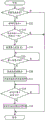
Fig. 3 is a flowchart of the 2 nd control in the case where the 1 st angle and the 2 nd angle executed by the control unit of fig. 1 are equal.
Fig. 4 is a flowchart of the 2 nd control in the case where the 1 st angle and the 2 nd angle executed by the control unit of fig. 1 are not equal.
Fig. 5 is a timing chart showing an example of the 2 nd control in the 1 st shift.
Fig. 6 is a timing chart showing an example of the 2 nd control in the 2 nd shift.
Fig. 7 is a flowchart of the 3 rd control executed by the control unit of embodiment 2.
Fig. 8 is a flowchart of the 4 th control executed by the control unit of embodiment 3.
Fig. 9 is a flowchart of the 5 th control of the 1 st modification.
Fig. 10 is a flowchart of the 6 th control of the 2 nd modification.
Detailed Description
(embodiment 1)
A bicycle equipped with the bicycle control device and the bicycle control system according to embodiment 1 will be described with reference to fig. 1.
The bicycle 10 includes a drive mechanism 12 and a bicycle control system 20.
The drive mechanism 12 includes a crank 12A and a pedal 12D. The crank 12A includes a crank axle 12B and a crank arm 12C. The drive mechanism 12 transmits the manual driving force applied to the pedals 12D to the rear wheels (not shown). The drive mechanism 12 is configured to transmit rotation of the crank 12A to the rear wheel via a chain, a belt, or a shaft (all of which are not shown). The drive mechanism 12 includes a front rotary body 12E coupled to the crankshaft 12B via a one-way clutch (not shown). The one-way clutch is configured to rotate the front rotor 12E forward when the crank 12A rotates forward, and to not rotate the front rotor 12E backward when the crank 12A rotates backward. The front rotator 12E includes a sprocket, a pulley, or a bevel gear (all of which are not shown). The front rotary body 12E may be coupled to the crankshaft 12B without a one-way clutch.
The bicycle control system 20 includes a bicycle control device 40, a transmission 22, a motor 24 and an operating portion 26. In one example, the bicycle control system 20 further includes an actuator 28 of the transmission 22, a drive circuit 30 of the motor 24, a battery pack 32, a torque sensor 34, a rotation angle sensor 36, and a shift state detecting device 38.
The transmission 22 and the actuator 28 constitute a transmission S. The transmission 22 changes the gear ratio r of the bicycle 10 in steps. In one example, the transmission 22 changes the speed of rotation input to the crankshaft 12B and transmits the changed speed to the rear wheels. In this case, the transmission 22 includes an internal transmission. The built-in transmission is provided around the crankshaft 12B or at the hub of the axle of the rear wheel. The built-in transmission may be provided in a power transmission path between the crank 12A and the front rotary body 12E. In another example, the transmission 22 changes the speed of the rotation input to the crankshaft 12B by switching the chain between a plurality of front sprockets or a plurality of rear sprockets, and transmits the changed speed to the rear wheel. In this case, the transmission 22 includes an externally mounted transmission (derailleur). The exterior transmission includes at least one of a front exterior transmission for changing a chain between a plurality of front sprockets (not shown) and a rear exterior transmission for changing a chain between a plurality of rear sprockets (not shown). The actuator 28 comprises an electric motor. The transmission 22 performs a shifting operation by driving the actuator 28, and changes the gear ratio r of the bicycle 10 in a stepwise manner. When the transmission 22 is an internal transmission, the shift operation includes an operation of changing a connection state of gears of a planetary gear mechanism constituting the inside of the transmission 22. When the transmission 22 is an externally mounted transmission, the shifting operation includes switching of the chain between the sprockets. The internal transmission may include a cvt (continuously Variable transmission) mechanism. In one example, the CVT mechanism is constituted by a planetary mechanism including an input body, an output body, and a transmission body, and the transmission body is rotated to continuously change the speed ratio r. The transmission S may include a structure other than the transmission 22 and the actuator 28.
The motor 24 and the drive circuit 30 constitute an auxiliary device a. The drive circuit 30 controls the electric power supplied from the battery pack 32 to the motor 24. The motor 24 assists in propelling the bicycle 10. The motor 24 comprises an electric motor. The motor 24 is provided to transmit the rotation to a transmission path of the human-powered driving force from the pedals 12D to the rear wheels or to the front wheels (not shown). The motor 24 is provided on the frame (not shown), the rear wheel, or the front wheel of the bicycle 10. In one example, the motor 24 is coupled to a power transmission path from the crankshaft 12B to the front rotor 12E. Preferably, a one-way clutch (not shown) is provided in the power transmission path between the motor 24 and the crank axle 12B so that the motor 24 is not rotated by the rotational force of the crank when the crank axle 12B is rotated in the forward direction of the bicycle 10. The auxiliary device a may include a structure other than the motor 24 and the drive circuit 30, and may include, for example, a speed reducer that outputs the rotation of the motor 24 by reducing the speed.
The operating portion 26 is operable by a rider. The operating portion 26 is mounted to a handlebar (not shown) of the bicycle 10. The operating portion 26 can communicate with the control portion 42 of the bicycle control device 40. The operation section 26 may be connected to the control section 42 by wired or wireless communication. The operation unit 26 can communicate with the control unit 42 via pcl (power Line communication), for example. The operating portion 26 transmits an output signal to the control portion 42 by the rider operating the operating portion 26. The output signals include an upshift signal to increase the gear ratio r of the bicycle 10 or a downshift signal to decrease the gear ratio r of the bicycle 10. The operation unit 26 includes, for example, an operation member, a sensor for detecting the operation of the operation member, and a circuit for communicating with the control unit 42 in accordance with an output signal of the sensor.
The operation unit 26 may be configured to output an output signal corresponding to a shift across a plurality of gears. In one example, when the operation unit 26 continuously performs the operation for increasing the speed ratio r for the 1 st predetermined time TX1 or more, the operation unit 26 transmits the output signal including the upshift signal to the control unit 42 a plurality of times. The number of times of transmission of the output signal may be increased as the operation time for increasing the speed ratio r input to the operation unit 26 is longer. When the operation unit 26 continuously performs the operation for reducing the speed ratio r for the 1 st predetermined time TX1 or more, the operation unit 26 transmits the output signal including the downshift signal to the control unit 42 a plurality of times. The number of times of transmission of the output signal may be increased as the operation time for reducing the gear ratio r input to the operation unit 26 is longer. The operation unit 26 can also transmit an output signal to the control unit 42 according to the time at which the operation unit 26 is operated within the 1 st predetermined time TX 1. In this case, the control unit 42 updates the required speed ratio rA in accordance with the number of shifts of the speed ratio r in order to change the output signal in accordance with the time at which the operation unit 26 is operated.
In another example, when the operation unit 26 performs the operation for increasing the speed ratio r a plurality of times within the 2 nd predetermined time TX2, the operation unit 26 transmits an output signal including an upshift signal to the control unit 42 every time the operation unit performs the operation. When the operation unit 26 performs the operation for reducing the speed ratio r a plurality of times within the 2 nd predetermined time TX2, the operation unit 26 transmits an output signal including the downshift signal to the control unit 42 every time it performs the operation. The control unit 42 executes the 1 st control for changing the required transmission ratio rA each time it receives the output signal. The operation unit 26 can also transmit an output signal corresponding to the number of times the operation unit 26 is operated within the 2 nd predetermined time TX2 to the control unit 42. In this case, the control unit 42 updates the required speed ratio rA in accordance with the number of shifts of the speed ratio r in order to change the output signal in accordance with the number of times the operation unit 26 is operated.
The output signal of the operation unit 26 may include a request for changing the speed ratio r over a plurality of gears. For example, the operation unit 26 is provided with a switch for changing the speed ratio r over a plurality of gears. The control unit 42 may set a shift request for changing the speed ratio r over a plurality of shift ranges in accordance with the content of the signal, the control state of the bicycle 10, or the like when the output signal of the operating unit 26 is received.
The battery pack 32 includes 1 or more battery cells. The battery unit includes a rechargeable battery. The battery pack 32 is mounted on the bicycle 10, and supplies electric power to other electrical components (e.g., the motor 24, the actuator 28, and the bicycle control device 40) electrically connected to the battery pack 32 by wires.
The torque sensor 34 outputs a signal corresponding to the manual driving force T. The torque sensor 34 detects a manual driving force T applied to the crank shaft 12B. The torque sensor 34 may be provided between the crank shaft 12B and the front rotary body 12E, may be provided on the crank shaft 12B or the front rotary body 12E, and may be provided on the crank arm 12C or the pedal 12D. The torque sensor 34 can be implemented by, for example, a strain sensor, a magnetic strain sensor, an optical sensor, a pressure sensor, or the like, and any sensor can be used as long as it outputs a signal corresponding to the manual driving force T applied to the crank arm 12C or the pedal 12D.
The rotation angle sensor 36 detects the rotation angle CA of the crank. The rotation angle sensor 36 is attached to a frame (not shown) of the bicycle 10 or a housing (not shown) of the auxiliary device a. The rotation angle sensor 36 includes a1 st element 36A that detects the magnetic field of the 1 st magnet M1 and a2 nd element 36B that outputs a signal corresponding to the positional relationship with the 2 nd magnet M2. The 1 st magnet M1 is provided on the crank axle 12B or the crank arm 12C, and is coaxially disposed on the crank axle 12B. The 1 st magnet M1 is a ring-shaped magnet, and a plurality of magnetic poles are alternately arranged in parallel in the circumferential direction. The 1 st element 36A detects the angle of rotation of the crank 12A relative to the frame. The 1 st element 36A outputs a signal of 1 cycle at an angle obtained by dividing 360 degrees by the number of magnetic poles of the same polarity when the crank 12A rotates 1 turn. The minimum value of the rotation angle of the crank 12A detectable by the rotation angle sensor 36 is 180 degrees or less, preferably 15 degrees, and more preferably 6 degrees. The 2 nd magnet M2 is provided on the crank axle 12B or the crank arm 12C. The 2 nd element 36B detects a reference angle of the crank 12A with respect to the frame (e.g., top dead center or bottom dead center of the crank 12A). The 2 nd element 36B outputs a signal of 1 cycle for 1 turn of the crankshaft 12B.
The rotation angle sensor 36 may be configured to include a magnetic sensor that outputs a signal according to the strength of the magnetic field, instead of the 1 st element 36A and the 2 nd element 36B. In this case, instead of the 1 st magnet M1 and the 2 nd magnet M2, a ring-shaped magnet whose magnetic field strength varies in the circumferential direction is provided on the crank shaft 12B coaxially with the crank shaft 12B. By using the magnetic sensor that outputs a signal according to the strength of the magnetic field, the rotational speed N of the crank and the rotational angle of the crank 12A can be detected by 1 sensor, and the structure and assembly can be simplified. The rotation angle sensor 36 is capable of detecting the rotation angle CA of the crank and also detecting the rotation speed N of the crank. The rotational speed N of the crank may also be detected using any one of the output of the 1 st element 36A, the output of the 2 nd element 36B, and the output of the magnetic sensor.
The shift state detecting device 38 detects the operating state of the transmission 22. In one example, the shift state detecting device 38 detects the position of a moving portion (not shown) of the transmission 22 that moves as the speed ratio r changes. In another example, the gear shift state detecting device 38 detects the gear ratio r according to the rotation speed of the rear wheel with respect to the rotation speed N of the crank.
The bicycle control device 40 includes a control unit 42. In one example, the bicycle control device 40 preferably further includes a storage unit 44.
The control unit 42 includes a calculation processing device that executes a predetermined control program. The operation Processing device includes, for example, a CPU (Central Processing Unit) or an MPU (micro Processing Unit). The control unit 42 may include 1 or more microcomputers. The storage unit 44 stores various control programs and information for various control processes. The storage unit 44 includes, for example, a nonvolatile memory and a volatile memory. The control section 42 also includes a timer.
The control unit 42 receives an output signal from the operation unit 26 as a shift request. The control unit 42 controls the transmission 22 and the motor 24 in response to a shift request for changing the speed ratio r. Specifically, when receiving an output signal including an upshift signal as a shift request, the control unit 42 executes 1 st control for increasing the speed ratio r (hereinafter referred to as "required speed ratio rA") corresponding to the shift request stored in the storage unit 44. When an output signal including a downshift signal is received as a shift request, the control unit 42 executes the 1 st control for reducing the requested speed ratio rA stored in the storage unit 44.
The 1 st control will be described with reference to fig. 2. The control unit 42 executes the 1 st control at predetermined intervals while the bicycle control device 40 is powered on.
The control unit 42 determines in step S11 whether or not a gear shift request is received. When the gear shift request is received, the control unit 42 updates the requested gear ratio rA stored in the storage unit 44 in step S12, and executes the process of step S11 again after a predetermined period. If the shift request is not received in step S11, the control unit 42 executes the process of step S11 again after a predetermined period.
The control unit 42 executes the 2 nd control for controlling the transmission 22 and the motor 24 in accordance with the required speed ratio rA updated by the 1 st control.
When the speed ratio r is changed over a plurality of gears in accordance with the shift request, the control unit 42 selectively executes one of the 1 st shift and the 2 nd shift. The control unit 42 selectively executes one of the 1 st shift and the 2 nd shift when the operation unit 26 is continuously operated for 1 st predetermined time TX1 or more or the operation unit 26 is operated a plurality of times within the 2 nd predetermined time TX 2. The control unit 42 selectively executes one of the 1 st shift and the 2 nd shift in response to a shift request received until the rotation angle CA of the crank reaches the 1 st angle CA 1.
Specifically, the control unit 42 executes one of the 1 st shift and the 2 nd shift, or neither of them, in accordance with the result of comparison between the required speed ratio rA updated in accordance with the shift request and the speed ratio r detected by the shift state detecting device 38. When the required speed ratio rA and the speed ratio r updated in accordance with the shift request match, the control unit 42 does not execute any of the 1 st shift and the 2 nd shift. The control portion 42 executes the 1 st shift with the difference of only 1 shift between the requested speed ratio rA and the speed ratio r updated according to the shift request. When the required speed ratio rA and the speed ratio r updated in response to the shift request differ by 2 or more steps, the control unit 42 executes at least one of the 1 st shift and the 2 nd shift in accordance with the difference between the required speed ratio rA and the speed ratio r. Further, when the required speed ratio rA is higher than the upper limit of the speed ratio r that can be achieved by the transmission 22, the control unit 42 does not perform the speed change exceeding the upper limit of the speed ratio r. When the required speed ratio rA is lower than the lower limit of the speed ratio r that can be achieved by the transmission 22, the control unit 42 does not shift beyond the lower limit of the speed ratio r. When the control unit 42 can control a plurality of the transmission 22, the upper limit and the lower limit of the speed ratio r represent the upper limit and the lower limit of the speed ratio of the bicycle 10 that can be realized by each transmission 22. In the 1 st control shown in fig. 2, the control unit 42 may set the required speed ratio rA to a speed ratio r that does not exceed the upper limit and the lower limit in step S12.
The control unit 42 executes one of the 1 st shift and the 2 nd shift in accordance with the 2 nd time T2 required to operate the transmission 22 to the required transmission ratio rA. The control unit 42 executes the 1 st shift when the 1 st timing T1 is equal to or longer than the 2 nd timing T2, and executes the 2 nd shift when the 1 st timing T1 is shorter than the 2 nd timing T2. The 2 nd time T2 differs accordingly from the difference between the requested speed ratio rA and the speed ratio r. In one example, the shift time required to increase by 1 shift position for each speed ratio r and the shift time required to decrease by 1 shift position for each speed ratio r are stored in the storage unit 44. The control unit 42 calculates the 2 nd time T2 by adding the shift time stored in the storage unit 44 to the current speed ratio r and the required speed ratio rA. In addition, at time 1T 1, if the gear shift is 1 shift position, the time for which the gear shift is possible is set for each gear ratio r. The shift time may be the same time or different times for each gear ratio r. The shift time may be set in the control unit 42 according to the characteristics and performance of the transmission 22. For example, the control unit 42 may be connected to an external device such as a personal computer by wireless or wired connection to set the shift time.
The control unit 42 restricts the output of the motor 24 and operates the transmission 22 until the required speed ratio rA is reached in the 1 st shift.
The control unit 42 receives the shift request, and when the rotation angle CA of the crank of the bicycle 10 reaches the 1 st angle CA1, restricts the output of the motor 24 and starts the operation of the transmission 22. The controller 42 limits the output of the motor 24 from when the rotation angle CA of the crank reaches the 1 st angle CA1 until the 1 st time T1 elapses. When the 1 st time T1 elapses, the control unit 42 relaxes the limitation on the output of the motor 24. Preferably, when the 1 st time T1 has elapsed, the control unit 42 ends the limitation of the output of the motor 24 and controls the motor 24 at the assist ratio immediately before the limitation of the output of the motor 24 is started.
The 1 st angle CA1 is included in a range from the 1 st rotation angle CX1, corresponding to one of the top dead center and the bottom dead center, of the crank 12C of the crank 12A to 45 degrees on the upstream side in the 1 st direction in which the crank 12A is rotated for propelling the bicycle 10 than the 1 st rotation angle CX 1. The 1 st direction is the rotational direction of the crank 12A with the bicycle 10 forward. When the rotation angle CA of the crank when the one crank arm 12C of the crank 12A is at the top dead center is 0 degrees and the rotation angle CA of the crank when the one crank arm 12C of the crank 12A is at the bottom dead center is 180 degrees, the 1 st rotation angle CX1 is one of 0 degrees and 180 degrees. In this case, the 1 st angle CA1 is included in one of the range from-45 degrees (215 degrees) to 0 degrees and the range from 135 degrees to 180 degrees. When the 1 st rotation angle CX1 is set to 0 degree, the 1 st angle CA1 is included in the range from-45 degrees (215 degrees) to 0 degree. When the 1 st rotation angle CX1 is set to 180 degrees, the 1 st angle CA1 is included in the range from 135 degrees to 180 degrees. The control unit 42 can also select which of the 0 degree and 180 degree 1 st rotation angle CX1 is set. For example, when the rotation angle CA of the crank when the shift request is received is in the range from 135 degrees to 215 degrees, the control unit 42 sets the 1 st rotation angle CX1 to 360 degrees (0). In this case, the 1 st angle CA1 is included in the range from 215 degrees to 360(0) degrees of the next rotation period. When the rotation angle CA of the crank when the shift request is received is in the range from 215 degrees to 135 degrees in the next rotation cycle, the control unit 42 sets the 1 st rotation angle CX1 to 180 degrees. In this case, the 1 st angle CA1 is included in the range from 135 degrees to 180 degrees of the next rotation cycle.
The control unit 42 restricts the output of the motor 24 and operates the transmission 22 during the 2 nd shift until the speed ratio r reaches the intermediate speed ratio rA to the required speed ratio rA, temporarily relaxes the restriction on the output of the motor 24, and then restricts the output of the motor 24 again and operates the transmission 22. The control unit 42 limits the output of the motor 24 and starts the operation of the transmission 22 when the rotation angle CA of the crank of the bicycle 10 reaches the 2 nd angle CA2 after the limitation of the output of the motor 24 is temporarily relaxed during the 2 nd shift. The controller 42 limits the output of the motor 24 from when the rotation angle CA of the crank reaches the 2 nd angle CA2 to when the 1 st time T1 elapses. When the 1 st time T1 elapses, the control unit 42 relaxes the limitation on the output of the motor 24. Preferably, when the 1 st time T1 has elapsed, the control unit 42 ends the limitation of the output of the motor 24 and controls the motor 24 at the assist ratio immediately before the limitation of the output of the motor 24 is started.
In one example, the 2 nd angle CA2 is equal to the 1 st angle CA 1. The 2 nd angle CA2 is included in a range from the 2 nd rotation angle CX2 corresponding to one of the top dead center and the bottom dead center of the crank arm 12C of the crank 12A to 45 degrees on the upstream side in the 1 st direction from the 2 nd rotation angle CX 2. In this case, when the 1 st rotation angle CX1 is 0 degrees, the 2 nd rotation angle CX2 is 0 degrees, and the 2 nd angle CA2 is included in the range from-45 degrees (215 degrees) to 0 degrees. When the 1 st rotation angle CX1 is 180 degrees, the 2 nd rotation angle CX2 is 180 degrees, and the 2 nd angle CA2 is included in the range from 135 degrees to 180 degrees.
In other examples, the 2 nd angle CA2 is different from the 1 st angle CA 1. The 2 nd angle CA2 is located on the upstream side or the downstream side in the 1 st direction than the 1 st angle CA 1. In one example, the 2 nd angle CA2 is on the downstream side of the 180 th angle CA 1. The 2 nd angle CA2 is included in a range from the 2 nd rotation angle CX2 corresponding to one crank arm 12C of the crank 12A and the other of the top dead center and the bottom dead center to 45 degrees on the upstream side in the 1 st direction from the 2 nd rotation angle CX 2. In this case, if the 1 st rotation angle CX1 is 0 degrees, the 2 nd rotation angle CX2 is 180 degrees, and the 2 nd angle CA2 is included in the range from 135 degrees to 180 degrees. When the 1 st rotation angle CX1 is 180 degrees, the 2 nd rotation angle CX2 is 0 degrees, and the 2 nd angle CA2 is included in the range from-45 degrees (215 degrees) to 0 degrees.
The 2 nd control will be described with reference to fig. 3. The control unit 42 executes the 2 nd control at predetermined intervals while the bicycle control device 40 is powered on. Here, a case where the 1 st angle CA1 is equal to the 2 nd angle CA2 will be described. In one example, the 1 st rotation angle CX1 corresponds to one of 0 degrees and 180 degrees, and the 2 nd rotation angle CX2 corresponds to one of 0 degrees and 180 degrees. In this case, the 2 nd control is executed only 1 time during one rotation of the crank 12A.
At step S21, the controller 42 detects the gear ratio r and shifts to step S22. In step S22, the control unit 42 determines whether the required speed ratio rA and the speed ratio r match. Specifically, the control unit 42 compares the required speed ratio rA updated in the 1 st control shown in fig. 2 with the speed ratio r detected by the speed change state detection device 38. When the required speed ratio rA and the speed ratio r match, the control unit 42 ends the process. When the required speed ratio rA and the speed ratio r are different, the control unit 42 proceeds to step S23.
The control unit 42 calculates the 2 nd time T2 in step S23, and sets the required transmission rA as the target transmission ratio rX when the 2 nd time T2 is less than the 1 st time T1. When the 2 nd time T2 is equal to or more than the 1 st time T1, the control unit 42 sets the speed ratio r between the current speed ratio r at which the transmission 22 can change speed and the required speed ratio rA at the 1 st time T1 as the target speed ratio rX. The target speed ratio rX set at the 2 nd time T2 at the 1 st time T1 or more corresponds to the intermediate speed ratio r.
The control section 42 determines in step S24 whether the 1 st angle CA1 is reached. If it is determined that the angle has not reached the 1 st angle CA1, the control unit 42 ends the process and executes the process from step S21 again after a predetermined period. When the required speed ratio rA is changed in the 1 st control until step S22 of the control cycle of the next 2 nd control, the control unit 42 performs the determination of step S22 using the changed required speed ratio rA. Therefore, the control unit 42 executes the processing of step S22 and thereafter in response to the shift request received until the rotation angle CA of the crank reaches the 1 st angle CA 1. When it is determined in step S24 that the angle reaches the 1 st angle CA1, the controller 42 starts limiting the output of the motor 24 in step S25, and proceeds to step S26. In step S26, the control unit 42 executes the shifting operation of the transmission 22 so as to change the speed ratio r to the target speed ratio rX set in step S23. When there is a difference of 2 or more gears between the current speed ratio r and the target speed ratio rX, the control unit 42 continuously operates the transmission 22.
Next, the control unit 42 determines in step S27 whether or not the 1 st time T1 has elapsed. Specifically, the controller 42 determines whether or not the time from reaching the 1 st angle CA1 is equal to or longer than the 1 st time T1. In another example, the controller 42 determines in step S27 whether or not the time after the start of limiting the output of the motor 24 is equal to or longer than the 1 st time T1. The controller 42 repeats the determination of step S27 until the 1 st time T1 elapses. When determining that the 1 st time T1 has elapsed, the control unit 42 alleviates the limitation on the output of the motor 24 in step S28, and ends the process. In one example, the control unit 42 controls the output of the motor 24 and ends the limitation of the output of the motor 24 in step S25 under the same conditions as before the limitation of the output of the motor 24.
When the target speed ratio rX set in step S23 is not the required speed ratio rA and when the required speed ratio rA is not updated or the difference between the current speed ratio r and the required speed ratio rA becomes large until step S22 of the control cycle of the next 2 nd control, the control unit 42 executes the 2 nd control so as to approach the required speed ratio rA in the control cycle of the next 2 nd control. Therefore, when the limitation of the output of the motor 24, which has been relaxed in step S28 of the control cycle of the 2 nd control performed immediately before, is again the 1 st angle CA1, the limitation of the output of the motor 24 is restarted.
Referring to fig. 4, the 2 nd control in the case where the 1 st angle CA1 and the 2 nd angle CA2 are different will be described. The control section 42 performs the processes up to steps S21 to S28 in the same order as the 2 nd control in the case where the 1 st angle CA1 and the 2 nd angle CA2 shown in fig. 3 are equal.
After the restriction on the output of the motor 24 is relaxed in step S28, the control unit 42 proceeds to step S62, and determines whether or not the required speed ratio rA and the speed ratio r match in step S62 by the same processing as in step S22. When the required speed ratio rA and the speed ratio r are different, the control unit 42 proceeds to step S63.
In step S63, the control unit 42 calculates a 4 th time T4 required to operate the transmission 22 to the required speed ratio rA, and sets the required speed ratio rA as the target speed ratio rX when the 4 th time T4 is less than the 3 rd time T3 stored in the storage unit 44 in advance. In one example, time 3T 3 is equal to time 1T 1. When the 4 th time T4 is equal to or more than the 3 rd time T3, the control unit 42 sets the speed ratio r between the current speed ratio r at which the transmission 22 can change speed and the required speed ratio rA at the 3 rd time T3 as the target speed ratio rX. The target speed ratio rX set at the 4 th time T4 at the 3 rd time T3 or more corresponds to the intermediate speed ratio r.
The control section 42 determines in step S64 whether the 2 nd angle CA2 is reached. If it is determined that the angle 2 CA2 has not been reached, the control unit 42 ends the process, and after a predetermined period, executes the process from step S21 in fig. 3 again. When it is determined in step S64 that the angle 2 CA2 has been reached, the controller 42 starts limiting the output of the motor 24 in step S65, and proceeds to step S66. Since the limitation of the output of the motor 24 is relaxed from step S28 to step S64, the limitation of the output of the motor 24 is restarted in step S65. In step S66, the control unit 42 executes the shifting operation of the transmission 22 so as to change the speed ratio r to the target speed ratio rX set in step S63. When there is a difference of 2 or more gears between the current speed ratio r and the target speed ratio rX, the control unit 42 continuously operates the transmission 22.
Next, the control unit 42 determines in step S67 whether or not the 3 rd time T3 has elapsed. Specifically, the controller 42 determines whether or not the time after reaching the 2 nd angle CA2 is equal to or longer than the 3 rd time T3. In another example, the control unit 42 determines in step S67 whether or not the time after the start of limiting the output of the motor 24 is equal to or longer than the 3 rd time T3. The controller 42 repeats the determination of step S67 until the 3 rd time T3 elapses. If it is determined that the 3 rd time T3 has elapsed, the control unit 42 relaxes the limitation on the output of the motor 24 in step S68, and ends the process. In one example, the control unit 42 controls the output of the motor 24 in step S65 using the same conditions as before the output of the motor 24 is limited, and ends the limitation of the output of the motor 24.
An execution mode in the case where the 1 st shift is executed by the 1 st control and the 2 nd control will be described with reference to fig. 5. The two-dot chain line in fig. 5(b) indicates the required speed ratio rA, and the solid line indicates the speed ratio r.
Time t11 represents a time when operation unit 26 is operated and an output signal including an upshift signal is transmitted to control unit 42. The control unit 42 increases the required transmission ratio rA by 1 gear by the 1 st control.
Time t12 represents a time when operation unit 26 is operated and an output signal including an upshift signal is transmitted to control unit 42. The control unit 42 further increases the required speed ratio rA changed at time t11 by 1 st gear by the 1 st control.
The time t13 indicates when the rotation angle CA of the crank reaches the 1 st angle CA 1. The control unit 42 compares the speed ratio r with the required speed ratio rA. Since the 2 nd time T2 required for the speed ratio r to be 2 steps greater is equal to or less than the 1 st time T1, the control unit 42 sets the speed ratio r that is 2 steps greater than the current speed ratio as the target speed ratio rX, and starts the limitation of the output of the motor 24 at time T13. The control unit 42 starts the limitation of the output of the motor 24, controls the transmission 22, and starts the change of the speed ratio r across 2 stages. The transmission 22 is preferably operated after the limitation of the output of the motor 24 is started, but the limitation of the output of the motor 24 and the operation of the transmission 22 may be started simultaneously, or the operation of the transmission 22 may be started immediately before the limitation of the output of the motor 24 is started.
The time T14 represents the time when the 1 st time T1 has elapsed from the time T13. The control unit 42 ends the limitation of the output of the motor 24.
An execution mode in the case where the 2 nd shift is executed by the 1 st control and the 2 nd control will be described with reference to fig. 6. The two-dot chain line in fig. 6(b) indicates the required speed ratio rA, and the solid line indicates the speed ratio r. The alternate long and short dash line in fig. 6(b) shows a change in the speed ratio r when the operation of the transmission 22 is not interrupted at time t25 and the operation of the transmission 22 is continued until the speed ratio r reaches the required speed ratio rA.
Time t21 represents a time when operation unit 26 is operated and an output signal including an upshift signal is transmitted to control unit 42. The control unit 42 increases the required transmission ratio rA by 1 gear by the 1 st control.
Time t22 represents a time when operation unit 26 is operated and an output signal including an upshift signal is transmitted to control unit 42. The control unit 42 further increases the required speed ratio rA changed at time t21 by 1 st gear by the 1 st control.
Time t23 represents a time when operation unit 26 is operated and an output signal including an upshift signal is transmitted to control unit 42. The control unit 42 further increases the required speed ratio rA changed at time t22 by 1 st gear by the 1 st control.
The time t24 indicates the time at which the rotation angle CA of the crank reaches the 1 st angle CA 1. The control unit 42 compares the speed ratio r with the required speed ratio rA. When the 2 nd time T2 required to reach the speed ratio r larger than the current by 3 steps is equal to or longer than the 1 st time T1 but the 2 nd time T2 required to reach the speed ratio r larger than the current by 2 steps is equal to or shorter than the 1 st time T1, the control unit 42 sets the speed ratio r larger than the current by 2 steps as the target speed ratio rX and starts the limitation of the output of the motor 24 at the time T24. The control unit 42 starts the limitation of the output of the motor 24, controls the transmission 22, and starts the change of the speed ratio r across 2 stages. The transmission 22 is preferably operated after the limitation of the output of the motor 24 is started, but the limitation of the output of the motor 24 and the operation of the transmission 22 may be started simultaneously, or the operation of the transmission 22 may be started immediately before the limitation of the output of the motor 24 is started. The gear ratio r in this case, which is 2 gears greater than the current gear, corresponds to the intermediate gear ratio r.
The time T25 represents the time when the 1 st time T1 has elapsed from the time T24. The control unit 42 alleviates the limitation of the output of the motor 24.
The time t26 indicates when the rotation angle CA of the crank reaches the 2 nd angle CA 2. The control unit 42 compares the current speed ratio r with the requested speed ratio rA, calculates the speed ratio r that is 1 gear larger than the current speed ratio rX, and starts limiting the output of the motor 24. The control unit 42 controls the transmission 22 to change the gear ratio r over 1 shift position.
The time T27 represents the time when the 1 st time T1 has elapsed from the time T26. The control unit 42 ends the limitation of the output of the motor 24. When the 1 st angle CA1 and the 2 nd angle CA2 are different, the time T27 indicates the time when the 3 rd time T3 has elapsed from the time T26.
(embodiment 2)
A bicycle control device 40 according to embodiment 2 will be explained with reference to fig. 1 and 7. The same reference numerals as in embodiment 1 are given to the same portions as in embodiment 1, and the description thereof is omitted. In embodiment 2, the 3 rd control is executed instead of the 1 st control and the 2 nd control of embodiment 1.
The control unit 42 receives an output signal from the operation unit 26 as a shift request. The control unit 42 controls the transmission 22 and the motor 24 in response to a shift request for changing the speed ratio r. Specifically, when an output signal including an upshift signal is received as a shift request, the control unit 42 executes the 3 rd control of the requested speed ratio rA to increase the speed ratio r. When an output signal including a downshift signal is received as a shift request, the control unit 42 executes the 3 rd control of the requested speed ratio rA for decreasing the speed ratio r.
The 3 rd control will be described with reference to fig. 7. The control unit 42 executes the 3 rd control at predetermined intervals while the bicycle control device 40 is powered on.
The control unit 42 determines in step S31 whether or not there is a shift request. If there is no speed change request, the process ends, and the determination process of step S31 is executed again for each predetermined cycle. If there is a shift request, the control unit 42 proceeds to step S32.
The controller 42 detects the gear ratio r in step S32 and proceeds to step S33. In step S33, the control unit 42 determines whether the required speed ratio rA and the speed ratio r match. Specifically, the control unit 42 compares the required speed ratio rA included in the output signal from the operation unit 26 with the speed ratio r detected by the speed change state detection device 38. When the required speed ratio rA and the speed ratio r match, the control unit 42 ends the process. When the required speed ratio rA and the speed ratio r are different, the control unit 42 proceeds to step S34.
In step S34, the control unit 42 calculates the 2 nd time T2 required to operate the transmission 22 to the required speed ratio rA, and proceeds to step S35.
The control section 42 determines in step S35 whether the 1 st angle CA1 is reached. If it is determined that the angle is not equal to the 1 st angle CA1, the controller 42 repeats the process of step S35 until the angle reaches the 1 st angle CA 1. When determining that the angle reaches the 1 st angle CA1, the controller 42 starts limiting the output of the motor 24 in step S36, and proceeds to step S37. In step S37, the control unit 42 executes the shifting operation of the transmission 22 until the required speed ratio rA is reached. When the current speed ratio r and the required speed ratio rA differ by 2 or more gears, the control unit 42 continuously operates the transmission 22.
Next, the control unit 42 determines in step S38 whether or not the 2 nd time T2 has elapsed. Specifically, the controller 42 determines whether or not the time after reaching the 1 st angle CA1 is equal to or longer than the 2 nd time T2. In another example, the control unit 42 determines whether or not the time after the start of the limitation of the output of the motor 24 is equal to or longer than the 2 nd time T2. The controller 42 repeats the determination of step S38 until the 2 nd time T2 elapses. When determining that the 2 nd time T2 has elapsed, the control unit 42 ends the limitation of the output of the motor 24 and ends the process in step S39. In one example, the control unit 42 controls the output of the motor 24 and ends the limitation of the output of the motor 24 in step S36 under the same conditions as before the limitation of the output of the motor 24.
(embodiment 3)
A bicycle control device 40 according to embodiment 3 will be explained with reference to fig. 1 and 8. The same reference numerals as in embodiment 2 are given to the same portions as in embodiment 2, and the description thereof is omitted. In embodiment 3, in the 3 rd control of embodiment 2, the 4 th control is executed in which the 1 st angle CA1 is changed in accordance with the shift request.
When the 1 st angle CA1 is reached, the control unit 42 restricts the output of the motor 24 and starts the transmission 22. When the transmission 22 is changed over a plurality of shift positions in response to the shift request, the control unit 42 changes the 1 st angle CA1 to the upstream side in the 1 st direction as compared with the case where the transmission 22 is changed by only 1 shift position in response to the shift request.
The 4 th control will be described with reference to fig. 8. The control unit 42 executes the 4 th control at predetermined intervals while the bicycle control device 40 is powered on.
The control unit 42 determines in step S31 whether or not there is a shift request. If there is no speed change request, the process ends and the determination process of step S31 is executed again for each predetermined cycle. If there is a shift request, the control unit 42 proceeds to step S32.
At step S32, the controller 42 detects the gear ratio r and shifts to step S33. In step S33, the control unit 42 determines whether the required speed ratio rA and the speed ratio r match. Specifically, the control unit 42 compares the required speed ratio rA included in the output signal from the operation unit 26 with the speed ratio r detected by the speed change state detection device 38. When the required speed ratio rA and the speed ratio r match, the control unit 42 ends the process. When the required speed ratio rA and the speed ratio r are different, the control unit 42 proceeds to step S41.
In step S41, the control unit 42 calculates the 2 nd time T2 required for operating the transmission 22 to the required speed ratio rA, sets the 1 st angle CA1 corresponding to the 2 nd time T2, and proceeds to step S35. When the transmission 22 is changed to the speed change ratio r by only 1 shift position in response to the shift request, the control unit 42 sets the initial value of the 1 st angle CA1 stored in the storage unit 44 in advance as the 1 st angle CA 1. When the transmission 22 is changed over a plurality of shift positions in response to the shift request, the controller 42 changes the 1 st angle CA1 to the upstream side in the 1 st direction as the 2 nd time T2 becomes longer. The storage unit 44 may store an association table of the 2 nd time T2 and the 1 st angle CA1 or a function of the 1 st angle CA1 and the 2 nd time T2. The control unit 42 may calculate the 1 st angle CA1 from the 2 nd time T2 by calculation using the association table or the function stored in the storage unit 44.
In step S35, the controller 42 determines whether the angle reaches the 1 st angle CA1 set in step S41. If it is determined that the angle is not equal to the 1 st angle CA1, the controller 42 repeats the process of step S35 until the angle reaches the 1 st angle CA 1. When determining that the angle reaches the 1 st angle CA1, the controller 42 starts limiting the output of the motor 24 in step S36, and proceeds to step S37. In step S37, the control unit 42 executes the shifting operation of the transmission 22 until the required speed ratio rA is reached. When the current speed ratio r and the required speed ratio rA differ by 2 or more gears, the control unit 42 continuously operates the transmission 22.
Next, the control unit 42 determines in step S38 whether or not the 2 nd time T2 has elapsed. Specifically, the controller 42 determines whether or not the time after reaching the 1 st angle CA1 is equal to or longer than the 2 nd time T2. In another example, the control unit 42 determines whether or not the time after the start of the limitation of the output of the motor 24 is equal to or longer than the 2 nd time T2. The controller 42 repeats the determination of step S38 until the 2 nd time T2 elapses. When determining that the 2 nd time T2 has elapsed, the control unit 42 ends the limitation of the output of the motor 24 and ends the process in step S39. In one example, the control unit 42 controls the output of the motor 24 in step S39 using the same conditions as before the output of the motor 24 is limited, and ends the limitation of the output of the motor 24.
(modification example)
The description of the embodiments is illustrative of the embodiments of the bicycle control device and the bicycle control system according to the present invention and is not intended to be limiting. The bicycle control device and the bicycle control system according to the present invention can be obtained by combining at least 2 modifications of the above embodiments, which are not inconsistent with each other, as shown below. In the following modification, the same reference numerals as in the embodiments are given to the portions common to the embodiments, and the description thereof is omitted.
The 2 nd control shown in fig. 3 of embodiment 1 may be changed to the 5 th control shown in fig. 9. In this modification, only the control of the transmission 22 is executed, and the control of the motor 24 is not executed. In the 5 th control shown in fig. 9, a process is performed in which the respective processes of step S25 and step S28 are omitted from the 2 nd control shown in fig. 3. When the 1 st angle CA1 and the 2 nd angle CA2 are different, the respective processes of step S65 and step S68 in fig. 4 are also omitted in the same manner as the respective processes of step S25 and step S28. In this modification, the bicycle control system 20 that does not include the motor 24 can execute the 5 th control of fig. 9.
The 2 nd control shown in fig. 3 of the 1 st embodiment can be changed to the 6 th control shown in fig. 10. In this modification, the controller 42 limits the output of the motor 24 from when the rotational angle CA of the crank becomes the 1 st angle CA1 to when the rotational angle CA of the crank becomes the 3 rd angle CA 3. Specifically, step S51 of fig. 10 is performed instead of step S27 of fig. 1. The controller 42 starts the output restriction of the motor 24 in step S25, starts the gear shift operation of the transmission in step S26, and then determines whether or not the rotation angle CA of the crank is the 3 rd angle CA3 in step S51. In one example, the 3 rd angle CA3 is included in a range from the 1 st rotation angle CX1 corresponding to one of the top dead center and the bottom dead center of the crank 12C to 45 degrees downstream of the 1 st rotation angle CX1 in the 1 st direction in which the crank 12A is rotated to propel the bicycle 10.
The modification shown in fig. 10 can be further modified as described below. In this modification, the controller 42 executes the 1 st shift when the predicted time TA from when the rotation angle CA of the crank becomes the 1 st angle CA1 to when it becomes the 3 rd angle CA3 is equal to or longer than the 2 nd time T2. When the predicted time TA is less than the 2 nd time T2, the control unit 42 executes the 2 nd shift. Specifically, in step S23 of fig. 10, the control unit 42 sets the required speed ratio rA as the target speed ratio rX when the predicted time TA is equal to or longer than the 2 nd time T2. Accordingly, the control unit 42 executes the 1 st shift through the processing of step S24 and subsequent steps. In step S23, when the predicted time TA is less than the 2 nd time T2, the control unit 42 sets the speed ratio r between the current speed ratio r at which the transmission 22 can change speed and the required speed ratio rA within the predicted time TA as the target speed ratio rX. Accordingly, the control unit 42 executes the 2 nd shift by the processing of the 6 th control after step S24 and the next time. The control unit 42 calculates the predicted time TA using the rotational speed N of the crank, which can be acquired by the rotational angle sensor 36.
Embodiment 1 can also be modified as described below. In this modification, the control unit 42 executes one of the 1 st shift and the 2 nd shift depending on the number of shift positions of the speed ratio r up to the required speed ratio rA. Specifically, in step S23 of fig. 3, the control unit 42 sets the required speed ratio rA as the target speed ratio rX when the number of speed ratios r up to the required speed ratio rA is equal to or less than a predetermined number of speed ratios. Accordingly, the control unit 42 executes the 1 st shift through the processing of step S24 and subsequent steps. In step S23, the control unit 42 sets the speed ratio r larger or smaller than the current speed ratio r by a predetermined number of steps as the target speed ratio rX when the speed ratio r to the required speed ratio rA is larger than the predetermined number of steps. Accordingly, the control unit 42 executes the 2 nd shift by the processing of the 2 nd control after step S24 and the next time thereafter. In this case, the speed ratio r larger or smaller than the current speed ratio r by a predetermined number of gears corresponds to the intermediate speed ratio r.
In the 3 rd control shown in fig. 7 of the 2 nd embodiment, only the transmission 22 may be controlled, and the motor 24 may be omitted. In this modification, a process is executed in which the respective processes of step S36 and step S39 are omitted from the 3 rd control. In this modification, the 3 rd control can be executed in the bicycle control system 20 that does not include the motor 24.
In the 4 th control shown in fig. 8 of embodiment 3, only the transmission 22 may be controlled and the motor 24 may be omitted. In this modification, a process is executed in which the respective processes of step S36 and step S39 are omitted from the 4 th control. In the bicycle control system 20 that does not include the motor 24, the 4 th control can be executed.
In the 3 rd control according to embodiment 2 and the 4 th control according to embodiment 3, the rotation angle CA of the crank for which the restriction of the motor 24 is completed can be set instead of the 2 nd time T2. Specifically, the controller 42 sets the range of the rotation angle CA of the crank for restricting the output of the motor 24 in step S34 of fig. 7 of embodiment 2 or step S41 of embodiment 3. The control unit 42 calculates the rotation angle CA of the crank at which the limitation of the output of the motor 24 is ended, in accordance with the 2 nd time T2. The longer the 2 nd time T2 is, the larger the range of the rotation angle CA of the crank in which the limitation of the output of the motor 24 is performed. Therefore, the rotation angle CA of the crank, at which the limitation of the output of the motor 24 is completed, is changed to the downstream side in the 1 st direction as the 2 nd time T2 becomes longer. In step S38, the controller 42 repeats the process of step S38 until the rotation angle CA of the crank at which the limitation of the output of the motor 24 is ended is reached.
In embodiments 1 and 2, the output signal of the operation unit 26 may include a request for changing the speed ratio r over a plurality of gears. In this case, for example, a switch for changing the speed ratio r across a plurality of gears is provided in the operation unit 26. When the output signal of the operating unit 26 is received, the control unit 42 may set a shift request for changing the speed ratio r across a plurality of shift positions according to the content of the signal, the control state of the bicycle 10, or the like.
In step S35 of the 3 rd control or the 4 th control according to embodiments 2 and 3, the control unit 42 may end the process when determining that the angle has not reached the 1 st angle CA1, and after a predetermined period, may perform the determination of step S31 again.
In embodiments 1 and 2, even if the 1 st angle CA1 is not reached, at least one of the limitation of the output of the motor 24 and the shift operation can be started. Specifically, the processing of step S24 of embodiment 1 or step S35 of embodiment 2 may be omitted. In this case, for example, the process may be immediately shifted to step S25 after step S23 is completed, or the process may be shifted to step S25 when the torque detected by the torque sensor 34 is equal to or less than a predetermined value. In the control of fig. 2 of fig. 4 according to embodiment 1, the process of step S64, which is the same as the process of step S24, may be omitted.
The control of each of the above embodiments may be executed in the 2 nd control, the 3 rd control, or the 4 th control in the automatic shifting in which the control unit 42 automatically controls the transmission 22 in accordance with 1 or more sensors mounted on the bicycle 10 to execute the shifting. The 1 or more sensors mounted on the bicycle 10 include at least 1 of a torque sensor, a vehicle speed sensor, and a cadence sensor. The control unit 42 determines whether or not there is a shift request in response to signals from one or more sensors mounted on the bicycle 10 and a control program for automatic shifting stored in the storage unit 44.
(remark 1)
A bicycle control device includes a control unit for controlling a transmission capable of changing a gear ratio of a bicycle in a stepwise manner and a motor for assisting propulsion of the bicycle in accordance with a shift request for changing the gear ratio,
the control part
When the speed ratio is changed over a plurality of gears in response to the speed change request, the output of the motor is limited, the transmission is operated until the speed ratio corresponding to the speed change request is reached, and when a2 nd time required for the speed change motor to operate until the speed ratio corresponding to the speed change request elapses, the limitation of the output of the motor is ended.
(remark 2)
A bicycle control device includes a control unit for controlling a transmission capable of changing a gear ratio of a bicycle in a stepwise manner and a motor for assisting propulsion of the bicycle in accordance with a shift request for changing the gear ratio,
the control part
Receiving the shift request, and when a crank of the bicycle is at a1 st angle on an upstream side in a1 st direction in which the crank is rotated to propel the bicycle from a rotation angle corresponding to a top dead center or a bottom dead center, controlling an output of the motor and starting an operation of the transmission,
when the transmission is changed over a plurality of shift positions in response to the shift request, the time for limiting the output of the motor is longer or the range of the rotation angle of the crank for limiting the output of the motor is wider than the time for changing the transmission by only 1 shift position in response to the shift request.
Description of the reference numerals
10: a bicycle; 12A: a crank; 12C: a crank arm; 20: a bicycle control system; 22: a transmission; 24: a motor; 26: an operation section; 40: a bicycle control device; 42: a control unit.
Claims (21)
1. A bicycle control device includes a control unit for controlling a transmission capable of changing a gear ratio of a bicycle in a stepwise manner and a motor for assisting propulsion of the bicycle in accordance with a shift request for changing the gear ratio,
the control part
Selectively executing one of a1 st shift and a2 nd shift when the speed ratio is changed over a plurality of gears in accordance with the shift request,
in the 1 st shift, the output of the motor is limited and the transmission is operated until the transmission ratio corresponding to the shift request is attained,
in the 2 nd shift, the output of the motor is limited, the transmission is operated until the transmission reaches an intermediate transmission ratio corresponding to the shift request, and after the limitation on the output of the motor is temporarily relaxed, the output of the motor is limited again, and the transmission is operated.
2. The bicycle control device according to claim 1, wherein the control unit receives the shift request, and when a rotation angle of a crank of the bicycle reaches a1 st angle, the control unit restricts an output of the motor and starts an operation of the transmission.
3. The bicycle control device according to claim 2, wherein said 1 st angle is included in the range of: the crank is rotated from a1 st rotation angle at which one crank arm of the crank corresponds to one of a top dead center and a bottom dead center to a 45 degree upstream in a1 st direction of the 1 st rotation angle from the 1 st rotation angle in order to propel the bicycle.
4. The bicycle control device according to any one of claims 1 to 3, wherein the control unit limits the output of the motor and starts the operation of the transmission when the rotation angle of the crank of the bicycle becomes the 2 nd angle after the limitation of the output of the motor is temporarily relaxed in the 2 nd shift.
5. The bicycle control device according to claim 4, wherein said 2 nd angle is included in the range of: the crank is rotated from a2 nd rotation angle at which one crank arm of the crank corresponds to the other of the top dead center and the bottom dead center to 45 degrees on the upstream side in the 1 st direction from the 2 nd rotation angle.
6. The bicycle control device according to claim 2 or 3, wherein the control unit limits the output of the motor and starts the operation of the transmission when the rotation angle of the crank of the bicycle becomes the 2 nd angle after the limitation of the output of the motor is temporarily relaxed during the 2 nd shift,
the 2 nd angle is equal to the 1 st angle.
7. The bicycle control apparatus according to claim 2 or 3, wherein the control unit selectively executes one of the 1 st shift and the 2 nd shift in response to the shift request received until the rotation angle of the crank reaches the 1 st angle.
8. The bicycle control device according to claim 2 or 3, wherein the control unit limits the output of the motor until a1 st time elapses from when the rotation angle of the crank becomes the 1 st angle.
9. The bicycle control device according to claim 2 or 3, wherein the control unit restricts the output of the motor from a time when the rotation angle of the crank reaches the 1 st angle until the rotation angle of the crank reaches the 3 rd angle.
10. The bicycle control apparatus according to any one of claims 1 to 3, wherein the control portion executes one of the 1 st shift and the 2 nd shift in accordance with at least one of a number of shift positions of the speed ratio up to the speed ratio corresponding to the speed change request and a2 nd time required for operating the transmission up to the speed ratio corresponding to the speed change request.
11. The bicycle control apparatus as set forth in claim 8,
the control part
Executing one of the 1 st shift and the 2 nd shift in accordance with a2 nd time required for operating the transmission to a speed ratio corresponding to the shift request,
the 1 st shift is executed when the 1 st timing is equal to or longer than the 2 nd timing, and the 2 nd shift is executed when the 1 st timing is shorter than the 2 nd timing.
12. The bicycle control apparatus as set forth in claim 9,
the control part
Executing one of the 1 st shift and the 2 nd shift in accordance with a2 nd time required for operating the transmission to a speed ratio corresponding to the shift request,
the 1 st shift is executed when the predicted time from when the rotation angle of the crank reaches the 1 st angle to when the rotation angle reaches the 3 rd angle is equal to or longer than the 2 nd time, and the 2 nd shift is executed when the predicted time is shorter than the 2 nd time.
13. A bicycle control device includes a control unit that operates a transmission that changes a gear ratio of a bicycle in a stepwise manner in response to a shift request for changing the gear ratio,
the control part
Selectively executing one of a1 st shift and a2 nd shift when the speed ratio is changed over a plurality of gears in accordance with the shift request,
in the 1 st shift, when the rotation angle of the crank of the bicycle is at the 1 st angle, the transmission is operated until the transmission ratio corresponding to the shift request is reached,
in the 2 nd shift, when the rotation angle of the crank of the bicycle is at the 1 st angle, the transmission is operated until the rotation angle reaches an intermediate speed ratio to the speed ratio corresponding to the shift request, and when the rotation angle of the crank is at the 2 nd angle, the operation of the transmission is restarted so as to change from the intermediate speed ratio to the speed ratio corresponding to the shift request.
14. The bicycle control device according to claim 13, wherein said 1 st angle is included in the range of: the crank is rotated from a1 st rotation angle at which one crank arm of the crank corresponds to one of a top dead center and a bottom dead center to a 45 degree upstream in a1 st direction of the 1 st rotation angle from the 1 st rotation angle in order to propel the bicycle.
15. The bicycle control device according to claim 14, wherein said 2 nd angle is included in the range of: a2 nd rotation angle of the crank arm corresponding to the other of the top dead center and the bottom dead center is up to 45 degrees on the upstream side in the 1 st direction from the 2 nd rotation angle; alternatively, the 2 nd angle is equal to the 1 st angle.
16. The bicycle control apparatus according to claim 14 or 15, wherein the control portion executes one of the 1 st shift and the 2 nd shift in accordance with at least one of the number of shift positions of the speed ratio corresponding to the shift request and a2 nd time required for operating the transmission up to the speed ratio corresponding to the shift request.
17. The bicycle control device according to claim 16, wherein the control unit executes the 1 st shift when a predetermined 1 st time is equal to or longer than the 2 nd time, and executes the 2 nd shift when the 1 st time is shorter than the 2 nd time.
18. The control device for a bicycle according to any one of claims 1 to 3, wherein the control portion receives an output signal from an operating portion operable by a rider as the shift request.
19. The bicycle control device according to claim 18, wherein the control unit selectively executes one of the 1 st shift and the 2 nd shift when the operating unit is continuously operated for 1 st or more predetermined time or when the operating unit is operated a plurality of times within a2 nd predetermined time.
20. A bicycle control system, comprising the bicycle control device of claim 18 or 19;
the above-mentioned speed change gear;
the motor; and
the operation part.
21. A bicycle control device includes a control unit for controlling a transmission capable of changing a gear ratio of a bicycle in a stepwise manner and a motor for assisting propulsion of the bicycle in accordance with a shift request for changing the gear ratio,
the control part
Receiving the shift request, and when a crank of the bicycle is at a1 st angle on an upstream side in a1 st direction in which the crank is rotated to propel the bicycle from a rotation angle corresponding to a top dead center or a bottom dead center, controlling an output of the motor and starting an operation of the transmission,
when the transmission is changed over a plurality of shift positions in response to the shift request, the 1 st angle is changed to the upstream side in the 1 st direction as compared with a case where the transmission is changed to the transmission only by 1 shift position in response to the shift request.
Applications Claiming Priority (2)
| Application Number | Priority Date | Filing Date | Title |
|---|---|---|---|
| JP2016-213623 | 2016-10-31 | ||
| JP2016213623A JP6670734B2 (en) | 2016-10-31 | 2016-10-31 | Bicycle control device and bicycle control system including the same |
Publications (2)
| Publication Number | Publication Date |
|---|---|
| CN108001608A CN108001608A (en) | 2018-05-08 |
| CN108001608B true CN108001608B (en) | 2020-12-22 |
Family
ID=61912173
Family Applications (1)
| Application Number | Title | Priority Date | Filing Date |
|---|---|---|---|
| CN201710957688.6A Active CN108001608B (en) | 2016-10-31 | 2017-10-16 | Bicycle control device and bicycle control system including the same |
Country Status (5)
| Country | Link |
|---|---|
| US (1) | US10562533B2 (en) |
| JP (1) | JP6670734B2 (en) |
| CN (1) | CN108001608B (en) |
| DE (1) | DE102017124175A1 (en) |
| TW (3) | TWI733548B (en) |
Families Citing this family (13)
| Publication number | Priority date | Publication date | Assignee | Title |
|---|---|---|---|---|
| JP6705760B2 (en) | 2017-01-31 | 2020-06-03 | 株式会社シマノ | Bicycle control device and bicycle control method |
| US10654542B2 (en) * | 2018-03-30 | 2020-05-19 | Shimano Inc. | Shifting control apparatus for human powered vehicle |
| JP7131966B2 (en) | 2018-05-30 | 2022-09-06 | 株式会社シマノ | Sensing devices, controllers for man-powered vehicles and components for man-powered vehicles |
| JP7036691B2 (en) | 2018-08-23 | 2022-03-15 | 株式会社シマノ | Shift control system for human-powered vehicles |
| JP7120871B2 (en) * | 2018-10-02 | 2022-08-17 | 株式会社シマノ | Controller and transmission system |
| JP7160617B2 (en) | 2018-10-03 | 2022-10-25 | 株式会社シマノ | Controller and transmission system |
| US10569836B2 (en) * | 2019-03-25 | 2020-02-25 | Hazem Nihad Hamed | Automatic bicycle shifter and chain driver |
| JP2022073186A (en) * | 2020-10-30 | 2022-05-17 | 株式会社シマノ | Control device for human power-driven vehicle |
| DE102020214163A1 (en) * | 2020-11-11 | 2022-05-12 | Robert Bosch Gesellschaft mit beschränkter Haftung | Method for shifting a transmission ratio of a shiftable transmission, control unit and vehicle |
| JP2022104359A (en) * | 2020-12-28 | 2022-07-08 | 株式会社シマノ | Control device for human-powered vehicle |
| NO346194B1 (en) * | 2021-01-14 | 2022-04-11 | Ca Tech Systems As | Pedally propelled vehicle gear system and method for operating such system |
| US11345441B2 (en) * | 2021-07-05 | 2022-05-31 | Hazem Nihad Hamed | Automatic bicycle shifter and torque computation algorithm |
| JP2024039457A (en) * | 2022-09-09 | 2024-03-22 | 株式会社シマノ | Control device for human-powered vehicles |
Citations (7)
| Publication number | Priority date | Publication date | Assignee | Title |
|---|---|---|---|---|
| CN1524764A (en) * | 2003-02-25 | 2004-09-01 | ��ʽ���絺Ұ | Bicycle shift control apparatus with preferential shifting |
| TW201309539A (en) * | 2011-08-24 | 2013-03-01 | J D Components Co Ltd | Automatic transmission bicycle with best gearshift occasion |
| CN102963487A (en) * | 2011-08-29 | 2013-03-13 | 株式会社岛野 | Fahrrad-antriebsvorrichtung |
| CN103569303A (en) * | 2012-07-18 | 2014-02-12 | 久鼎金属实业股份有限公司 | Booster bicycle gear shifting system with pedaling position as judgment basis |
| CN203581294U (en) * | 2013-04-15 | 2014-05-07 | 株式会社岛野 | Control device for bicycle part |
| EP2783969A1 (en) * | 2013-03-29 | 2014-10-01 | Yamaha Hatsudoki Kabushiki Kaisha | Controller for electric bicycle, power unit for electric bicycle, and electric bicycle |
| CN105799851A (en) * | 2015-01-15 | 2016-07-27 | 株式会社岛野 | Control apparatus for bicycle assist device and bicycle assist device |
Family Cites Families (10)
| Publication number | Priority date | Publication date | Assignee | Title |
|---|---|---|---|---|
| JPS5496158A (en) | 1978-01-07 | 1979-07-30 | Dainippon Screen Mfg | Needle selector of automatic weft nitting machine |
| US5599244A (en) * | 1995-08-14 | 1997-02-04 | Ethington; Russell A. | Automatic transmission shifter for velocipedes |
| JP2001010581A (en) | 1999-06-30 | 2001-01-16 | Yamaha Motor Co Ltd | Automatic transmission device of bicycle |
| JP3717076B2 (en) | 2003-03-11 | 2005-11-16 | 株式会社シマノ | Shift control device for motorcycle |
| DE60302782T2 (en) * | 2003-07-24 | 2006-07-13 | Campagnolo S.R.L. | Method for shifting a bicycle transmission with electric auxiliary drive and switching device |
| US7713164B2 (en) * | 2007-06-26 | 2010-05-11 | Ford Global Technologies, Llc | Double step gear shifting in a hybrid electric vehicle |
| JP5211212B2 (en) * | 2011-07-27 | 2013-06-12 | 株式会社シマノ | Bicycle motor control device and bicycle |
| JP5689849B2 (en) * | 2012-05-18 | 2015-03-25 | マイクロスペース株式会社 | Motor drive control device |
| TWI525017B (en) * | 2012-10-25 | 2016-03-11 | A shift system that reduces the speed of the motor when the bicycle is turned | |
| JP5685635B2 (en) | 2013-10-28 | 2015-03-18 | 株式会社シマノ | Bicycle control device |
-
2016
- 2016-10-31 JP JP2016213623A patent/JP6670734B2/en active Active
-
2017
- 2017-10-16 CN CN201710957688.6A patent/CN108001608B/en active Active
- 2017-10-17 DE DE102017124175.2A patent/DE102017124175A1/en active Pending
- 2017-10-20 TW TW109126850A patent/TWI733548B/en active
- 2017-10-20 TW TW106136061A patent/TWI715810B/en active
- 2017-10-20 TW TW109126851A patent/TWI733549B/en active
- 2017-10-26 US US15/794,366 patent/US10562533B2/en active Active
Patent Citations (7)
| Publication number | Priority date | Publication date | Assignee | Title |
|---|---|---|---|---|
| CN1524764A (en) * | 2003-02-25 | 2004-09-01 | ��ʽ���絺Ұ | Bicycle shift control apparatus with preferential shifting |
| TW201309539A (en) * | 2011-08-24 | 2013-03-01 | J D Components Co Ltd | Automatic transmission bicycle with best gearshift occasion |
| CN102963487A (en) * | 2011-08-29 | 2013-03-13 | 株式会社岛野 | Fahrrad-antriebsvorrichtung |
| CN103569303A (en) * | 2012-07-18 | 2014-02-12 | 久鼎金属实业股份有限公司 | Booster bicycle gear shifting system with pedaling position as judgment basis |
| EP2783969A1 (en) * | 2013-03-29 | 2014-10-01 | Yamaha Hatsudoki Kabushiki Kaisha | Controller for electric bicycle, power unit for electric bicycle, and electric bicycle |
| CN203581294U (en) * | 2013-04-15 | 2014-05-07 | 株式会社岛野 | Control device for bicycle part |
| CN105799851A (en) * | 2015-01-15 | 2016-07-27 | 株式会社岛野 | Control apparatus for bicycle assist device and bicycle assist device |
Also Published As
| Publication number | Publication date |
|---|---|
| US10562533B2 (en) | 2020-02-18 |
| DE102017124175A1 (en) | 2018-05-03 |
| CN108001608A (en) | 2018-05-08 |
| TWI715810B (en) | 2021-01-11 |
| JP2018070001A (en) | 2018-05-10 |
| JP6670734B2 (en) | 2020-03-25 |
| TWI733549B (en) | 2021-07-11 |
| TW202043094A (en) | 2020-12-01 |
| TW202041415A (en) | 2020-11-16 |
| US20180118211A1 (en) | 2018-05-03 |
| TWI733548B (en) | 2021-07-11 |
| TW201817639A (en) | 2018-05-16 |
Similar Documents
| Publication | Publication Date | Title |
|---|---|---|
| CN108001608B (en) | Bicycle control device and bicycle control system including the same | |
| US20210031882A1 (en) | Bicycle controller and bicycle control system including bicycle controller | |
| JP6916047B2 (en) | Bicycle control device | |
| CN107298151B (en) | Bicycle control device | |
| US10106223B2 (en) | Bicycle control system | |
| CN107021180B (en) | Bicycle control device and bicycle speed change system | |
| US9546731B2 (en) | Bicycle gear changing control apparatus, electrically assisted system, and bicycle gear changing control method | |
| CN108372900B (en) | Bicycle control device and bicycle control method | |
| JP2019172215A (en) | Control device for man power drive vehicle | |
| JP2021046205A (en) | Bicycle controller | |
| EP2783969B1 (en) | Controller for electric bicycle, power unit for electric bicycle, and electric bicycle | |
| JP7324646B2 (en) | Control device for man-powered vehicles | |
| JP6756887B2 (en) | Bicycle control device and bicycle control system including this | |
| JP6759436B2 (en) | Bicycle control device and bicycle control system including this | |
| JP2021107188A (en) | Electrically-assisted bicycle, driving system thereof, and manufacturing method | |
| US20230382490A1 (en) | Human-powered vehicle control device, human-powered vehicle component, and human-powered vehicle drive unit | |
| JP7160977B2 (en) | Manpowered vehicle controller |
Legal Events
| Date | Code | Title | Description |
|---|---|---|---|
| PB01 | Publication | ||
| PB01 | Publication | ||
| SE01 | Entry into force of request for substantive examination | ||
| SE01 | Entry into force of request for substantive examination | ||
| GR01 | Patent grant | ||
| GR01 | Patent grant |