CN108372900B - Bicycle control device and bicycle control method - Google Patents
Bicycle control device and bicycle control method Download PDFInfo
- Publication number
- CN108372900B CN108372900B CN201810077258.XA CN201810077258A CN108372900B CN 108372900 B CN108372900 B CN 108372900B CN 201810077258 A CN201810077258 A CN 201810077258A CN 108372900 B CN108372900 B CN 108372900B
- Authority
- CN
- China
- Prior art keywords
- bicycle
- transmission
- motor
- shift operation
- output
- Prior art date
- Legal status (The legal status is an assumption and is not a legal conclusion. Google has not performed a legal analysis and makes no representation as to the accuracy of the status listed.)
- Active
Links
Images


Classifications
-
- B—PERFORMING OPERATIONS; TRANSPORTING
- B62—LAND VEHICLES FOR TRAVELLING OTHERWISE THAN ON RAILS
- B62M—RIDER PROPULSION OF WHEELED VEHICLES OR SLEDGES; POWERED PROPULSION OF SLEDGES OR SINGLE-TRACK CYCLES; TRANSMISSIONS SPECIALLY ADAPTED FOR SUCH VEHICLES
- B62M6/00—Rider propulsion of wheeled vehicles with additional source of power, e.g. combustion engine or electric motor
- B62M6/40—Rider propelled cycles with auxiliary electric motor
- B62M6/45—Control or actuating devices therefor
- B62M6/50—Control or actuating devices therefor characterised by detectors or sensors, or arrangement thereof
-
- B—PERFORMING OPERATIONS; TRANSPORTING
- B62—LAND VEHICLES FOR TRAVELLING OTHERWISE THAN ON RAILS
- B62M—RIDER PROPULSION OF WHEELED VEHICLES OR SLEDGES; POWERED PROPULSION OF SLEDGES OR SINGLE-TRACK CYCLES; TRANSMISSIONS SPECIALLY ADAPTED FOR SUCH VEHICLES
- B62M6/00—Rider propulsion of wheeled vehicles with additional source of power, e.g. combustion engine or electric motor
- B62M6/40—Rider propelled cycles with auxiliary electric motor
- B62M6/45—Control or actuating devices therefor
-
- B—PERFORMING OPERATIONS; TRANSPORTING
- B62—LAND VEHICLES FOR TRAVELLING OTHERWISE THAN ON RAILS
- B62J—CYCLE SADDLES OR SEATS; AUXILIARY DEVICES OR ACCESSORIES SPECIALLY ADAPTED TO CYCLES AND NOT OTHERWISE PROVIDED FOR, e.g. ARTICLE CARRIERS OR CYCLE PROTECTORS
- B62J43/00—Arrangements of batteries
- B62J43/10—Arrangements of batteries for propulsion
- B62J43/13—Arrangements of batteries for propulsion on rider-propelled cycles with additional electric propulsion
-
- B—PERFORMING OPERATIONS; TRANSPORTING
- B62—LAND VEHICLES FOR TRAVELLING OTHERWISE THAN ON RAILS
- B62M—RIDER PROPULSION OF WHEELED VEHICLES OR SLEDGES; POWERED PROPULSION OF SLEDGES OR SINGLE-TRACK CYCLES; TRANSMISSIONS SPECIALLY ADAPTED FOR SUCH VEHICLES
- B62M15/00—Transmissions characterised by use of crank shafts and coupling rods
-
- B—PERFORMING OPERATIONS; TRANSPORTING
- B62—LAND VEHICLES FOR TRAVELLING OTHERWISE THAN ON RAILS
- B62M—RIDER PROPULSION OF WHEELED VEHICLES OR SLEDGES; POWERED PROPULSION OF SLEDGES OR SINGLE-TRACK CYCLES; TRANSMISSIONS SPECIALLY ADAPTED FOR SUCH VEHICLES
- B62M25/00—Actuators for gearing speed-change mechanisms specially adapted for cycles
- B62M25/08—Actuators for gearing speed-change mechanisms specially adapted for cycles with electrical or fluid transmitting systems
-
- B—PERFORMING OPERATIONS; TRANSPORTING
- B62—LAND VEHICLES FOR TRAVELLING OTHERWISE THAN ON RAILS
- B62M—RIDER PROPULSION OF WHEELED VEHICLES OR SLEDGES; POWERED PROPULSION OF SLEDGES OR SINGLE-TRACK CYCLES; TRANSMISSIONS SPECIALLY ADAPTED FOR SUCH VEHICLES
- B62M9/00—Transmissions characterised by use of an endless chain, belt, or the like
- B62M9/04—Transmissions characterised by use of an endless chain, belt, or the like of changeable ratio
- B62M9/06—Transmissions characterised by use of an endless chain, belt, or the like of changeable ratio using a single chain, belt, or the like
- B62M9/10—Transmissions characterised by use of an endless chain, belt, or the like of changeable ratio using a single chain, belt, or the like involving different-sized wheels, e.g. rear sprocket chain wheels selectively engaged by the chain, belt, or the like
- B62M9/12—Transmissions characterised by use of an endless chain, belt, or the like of changeable ratio using a single chain, belt, or the like involving different-sized wheels, e.g. rear sprocket chain wheels selectively engaged by the chain, belt, or the like the chain, belt, or the like being laterally shiftable, e.g. using a rear derailleur
-
- B—PERFORMING OPERATIONS; TRANSPORTING
- B62—LAND VEHICLES FOR TRAVELLING OTHERWISE THAN ON RAILS
- B62J—CYCLE SADDLES OR SEATS; AUXILIARY DEVICES OR ACCESSORIES SPECIALLY ADAPTED TO CYCLES AND NOT OTHERWISE PROVIDED FOR, e.g. ARTICLE CARRIERS OR CYCLE PROTECTORS
- B62J45/00—Electrical equipment arrangements specially adapted for use as accessories on cycles, not otherwise provided for
- B62J45/20—Cycle computers as cycle accessories
Abstract
The invention provides a bicycle control device and a bicycle control method, which can properly reduce the output of a motor when a speed changer operates. The bicycle control device includes a control unit that controls a motor that assists propulsion of a bicycle, and the control unit is configured to reduce an output of the motor to a limit value or less when a transmission that changes a gear ratio of the bicycle performs a shifting operation, and is configured to change at least one of the limit value of the output of the motor and a time period during which the output of the motor is reduced when the transmission performs the shifting operation, in accordance with at least one of an operating state of the transmission during the shifting operation and a parameter of the bicycle that changes as a result of the transmission performing the shifting operation.
Description
Technical Field
The present invention relates to a bicycle control device and a bicycle control method.
Background
The bicycle control device disclosed in patent document 1 reduces the output of a motor that assists propulsion of a bicycle when a transmission that changes a gear ratio of the bicycle is operated.
Patent document 1: japanese patent No. 5496158.
Disclosure of Invention
The present invention aims to provide a bicycle control device and a bicycle control method, which can properly reduce the output of a motor when a speed changer operates.
The bicycle control device according to claim 1 of the present invention includes a control unit that controls a motor that assists propulsion of a bicycle, wherein the control unit is configured to reduce an output of the motor to a limit value or less when a transmission that changes a gear ratio of the bicycle performs a shifting operation, and is configured to be capable of changing at least one of the limit value of the output of the motor and a time period during which the output of the motor is reduced when the transmission performs the shifting operation, in accordance with at least one of an operating state of the transmission during the shifting operation and a parameter of the bicycle that changes when the transmission performs the shifting operation.
According to the above aspect 1, the output of the motor can be appropriately reduced when the transmission is operated, as compared to a case where the control is performed uniformly regardless of the operating state of the transmission and the parameter of the bicycle that changes when the transmission performs a shifting operation.
In the bicycle control device according to the 2 nd aspect of the 1 st aspect, the shift operation includes a1 st shift operation and a2 nd shift operation to be executed after the 1 st shift operation, and the control unit causes at least one of the limit value of the output of the motor and a time period for which the output of the motor is to be decreased in a case where the 2 nd shift operation is executed to be different from at least one of the limit value of the output of the motor and a time period for which the output of the motor is to be decreased in a case where the 1 st shift operation is executed, in accordance with at least one of an operating state of the transmission in the 1 st shift operation and a parameter of the bicycle that is changed by the transmission executing the 1 st shift operation.
According to the 2 nd aspect, the output of the motor can be appropriately reduced in the 2 nd shift operation performed after the 1 st shift operation, based on the result of the 1 st shift operation.
In the bicycle control device according to the 3 rd aspect of the 2 nd aspect, when the speed ratio is reduced in the 1 st shifting operation, the 2 nd shifting operation includes all of the shifting operations that are executed after the 1 st shifting operation and that are changed so as to reduce the speed ratio.
According to the 3 rd aspect, the output of the motor can be appropriately reduced in all the 2 nd shift operations executed to reduce the gear ratio after the 1 st shift operation, based on the result of the 1 st shift operation.
In the bicycle control device according to the 4 th aspect from the 2 nd aspect, when the speed ratio is increased in the 1 st shifting operation, the 2 nd shifting operation includes all of the shifting operations that are executed after the 1 st shifting operation and that are changed so as to increase the speed ratio.
According to the above-described aspect 4, the output of the motor can be appropriately reduced in all the 2 nd shift operations executed to increase the gear ratio after the 1 st shift operation, based on the result of the 1 st shift operation.
In the bicycle control device according to the 5 th aspect from the 2 nd aspect, the 2 nd shifting operation includes all of the shifting operations performed after the 1 st shifting operation.
According to the above-described aspect 5, the output of the motor can be appropriately reduced in all the 2 nd shift operations executed after the 1 st shift operation, based on the result of the 1 st shift operation.
In the bicycle control device according to the 6 th aspect from the 2 nd aspect, when the transmission changes the speed ratio from the 1 st speed ratio to the 2 nd speed ratio in the 1 st shifting operation, the 2 nd shifting operation includes all of the shifting operations that are executed after the 1 st shifting operation and in which the transmission changes the speed ratio from the 1 st speed ratio to the 2 nd speed ratio.
According to the 6 th aspect, the output of the motor can be appropriately reduced in the 2 nd shift operation performed after the 1 st shift operation and changed from the 1 st gear ratio to the 2 nd gear ratio, based on the result of the 1 st shift operation when changing from the 1 st gear ratio to the 2 nd gear ratio.
In the 7 th control device for a bicycle according to any one of the 2 nd to 6 th aspects, the control unit may be configured to perform at least one of a decrease in the limit value of the output of the motor and an increase in a time period for which the output of the motor is decreased when the transmission performs the 2 nd shift operation, if the transmission performs the 1 st shift operation and the 1 st shift operation is not completed or the transmission ratio is not changed within a predetermined period.
According to the 7 th aspect, if the 1 st shift operation is not completed or the speed ratio is not changed within a predetermined period, the limit value of the output of the motor is decreased and/or the time for decreasing the output of the motor is increased in the 2 nd shift operation performed after the 1 st shift operation. Therefore, the possibility of a shift failure is reduced in the 2 nd shift operation.
In the bicycle control device according to the 8 th aspect of the 7 th aspect, the control portion may decrease the limit value of the output of the motor in a case where the transmission performs the 2 nd shift operation if the transmission performs the 1 st shift operation without decreasing the output of the motor to a predetermined value and the 1 st shift operation is not completed or the speed ratio is not changed within the predetermined period, as compared to a case where the transmission performs the 1 st shift operation, and may decrease the limit value of the output of the motor in a case where the transmission performs the 2 nd shift operation if the transmission performs the 1 st shift operation and the 1 st shift operation is not completed or the speed ratio is not changed within the predetermined period and the output of the motor is decreased to a predetermined value, the time for decreasing the output of the motor is increased as compared with the case where the transmission performs the 1 st shift operation.
According to the 8 th aspect, when the transmission is difficult to complete the shift operation, the output of the motor is first reduced to a predetermined value, and then the time for reducing the output of the motor is increased. Therefore, it is possible to suppress the period during which the assist of the manual driving force by the motor is not performed from becoming long.
In the bicycle control device according to the 9 th aspect of the 7 th or 8 th aspect, if the transmission performs the 1 st shifting operation, and the number of times the 1 st shifting operation is not completed or the number of times the transmission ratio is not changed reaches the 1 st number of times within the predetermined period, the control unit performs at least one of a decrease in the limit value of the output of the motor and an increase in time for which the output of the motor is decreased when the transmission performs the 2 nd shifting operation, as compared to when the transmission performs the 1 st shifting operation.
According to the above-described 9 th aspect, when it is erroneously detected that the 1 st shift operation is not completed within a predetermined period or when it is erroneously detected that the speed ratio is not changed within a predetermined period, it is suppressed that at least one of the limit value of the output of the motor and the time for which the output of the motor is decreased is changed when the 2 nd shift operation is executed.
In the bicycle control device according to the 10 th aspect from the 2 nd aspect, the control unit may be configured to perform at least one of an increase in the limit value of the output of the motor and a decrease in a time period during which the output of the motor is decreased when the transmission performs the 2 nd shift operation, if the transmission performs the 1 st shift operation and the 1 st shift operation is completed or the transmission ratio is changed within a predetermined period of time, as compared to a case where the transmission performs the 1 st shift operation.
According to the 10 th aspect, if the 1 st shift operation is completed or the speed ratio is changed within a predetermined period, at least one of the increase of the limit value of the output of the motor and the decrease of the time for decreasing the output of the motor is performed in the 2 nd shift operation executed after the 1 st shift operation. Therefore, in the 2 nd shift operation, the period during which the assist force is insufficient or intermittent can be shortened as much as possible.
In the bicycle control device according to claim 11 of any one of the 7 th to 9 th aspects, if the transmission performs the 1 st shift operation, and the 1 st shift operation is completed or the gear ratio is changed within the predetermined period, the control unit increases at least one of the limit value of the output of the motor and the time for which the output of the motor is decreased when the transmission performs the 2 nd shift operation, as compared to when the transmission performs the 1 st shift operation.
According to the 11 th aspect, if the 1 st shift operation is completed or the gear ratio is changed within a predetermined period, at least one of the increase of the limit value of the output of the motor and the decrease of the time for decreasing the output of the motor is performed in the 2 nd shift operation performed after the 1 st shift operation. Therefore, in the 2 nd shift operation, the period during which the assist force is insufficient or intermittent can be shortened as much as possible.
In the bicycle control device according to the 12 th aspect of the 10 th or 11 th aspect, the control unit may be configured such that the transmission performs the 1 st shift operation, the 1 st shift operation is completed or the gear ratio is changed within the predetermined period in a state where a time for which the output of the motor is reduced is longer than a predetermined value, in which case, when the transmission performs the 2 nd shift operation, the time for which the output of the motor is reduced as compared with a case where the transmission performs the 1 st shift operation, and when the transmission performs the 1 st shift operation, the 1 st shift operation is completed or the gear ratio is changed within the predetermined period in a state where the time for which the output of the motor is reduced is equal to or less than the predetermined value, in which case, when the transmission performs the 2 nd shift operation, the limit value of the output of the motor is increased as compared with a case where the transmission performs the 1 st shift operation.
According to the 12 th aspect, when the speed is easily changed, the time for decreasing the output of the motor is first shortened to a predetermined value, and then the limit value of the output of the motor is increased. Therefore, it is possible to suppress the period during which the assist of the manual driving force by the motor is not performed from becoming long.
In the bicycle control device according to claim 13 of any one of the 10 th to 12 th aspects, when the transmission performs the 1 st shift operation, and the number of times the 1 st shift operation is completed or the number of times the speed change ratio is changed reaches the 2 nd number of times within the predetermined period, the control unit increases at least one of the limit value of the output of the motor and the time for which the output of the motor is decreased when the transmission performs the 2 nd shift operation, as compared with a case where the transmission performs the 1 st shift operation.
According to the 13 th aspect, when it is erroneously detected that the 1 st shift operation is completed within a predetermined period, or when it is erroneously detected that the speed ratio is changed within a predetermined period, it is suppressed that at least one of the limit value of the output of the motor and the time for which the output of the motor is decreased is changed when the 2 nd shift operation is executed.
In the bicycle control device according to the 14 th aspect of any one of the 11 th to 13 th aspects, the parameter of the bicycle includes a rotation speed of a crank of the bicycle.
According to the 14 th aspect, whether or not the speed ratio is changed can be appropriately determined based on the rotation speed of the crank of the bicycle.
A bicycle control apparatus according to an aspect of the present invention is a bicycle control apparatus including a control unit configured to control a motor for assisting propulsion of a bicycle, wherein the control unit is configured to decrease an output of the motor when a transmission for changing a gear ratio of the bicycle performs a shifting operation, to end control for decreasing the output of the motor before a predetermined period elapses and the shifting operation is completed or the gear ratio is changed, and to end control for decreasing the output of the motor when the predetermined period elapses and the shifting operation or the change of the gear ratio is not completed.
According to the 15 th aspect, the output of the motor can be appropriately reduced when the transmission is operated, as compared with a case where the output of the motor is always reduced when a predetermined period elapses.
In the bicycle control device according to the 16 th aspect of the 15 th aspect, the predetermined period is set independently corresponding to the gear ratio to be shifted.
According to the 16 th aspect, the output of the motor can be reduced in a time period corresponding to the gear ratio.
In the bicycle control device according to the 17 th aspect of any one of the 7 th to 16 th aspects, the control unit determines whether or not the speed ratio has changed based on a rotation speed of a crank of the bicycle.
According to the 17 th aspect, it is possible to appropriately determine whether or not the speed ratio has changed, based on the rotation speed of the crank of the bicycle.
In the bicycle control device according to the 18 th aspect of the 17 th aspect, the control unit executes control corresponding to determination based on a rotation speed of the crank of the bicycle only when a manual driving force input to the crank of the bicycle is equal to or greater than a predetermined value.
According to the 18 th aspect, the control corresponding to the determination of the rotation speed of the crank by the bicycle can be executed only when the gear ratio is easily and accurately determined.
The control device for a bicycle according to the 19 th aspect of any one of the 1 st to 18 th aspects, wherein the control unit controls an electric actuator that causes the transmission to perform the shifting operation.
According to the 19 th aspect, the transmission can be operated by controlling the electric actuator.
In the bicycle control device according to the 20 th aspect of the 19 th aspect, the control unit may operate the transmission when a rotation angle of a crank of the bicycle is within a predetermined range, the predetermined range including a top dead center or a bottom dead center of the crank of the bicycle.
According to the 20 th aspect, the transmission can be operated in a range including the top dead center or the bottom dead center of the crank where the manual driving force is small.
One aspect of the method of controlling a bicycle according to the 21 st aspect of the present invention is a method of controlling a bicycle in which a motor for assisting propulsion of a bicycle is controlled, wherein when a transmission for changing a gear ratio of the bicycle performs a shifting operation, an output of the motor is reduced to a limit value or less, and at least one of the limit value of the output of the motor and a time period for which the output of the motor is reduced when the transmission performs the shifting operation is changed in accordance with at least one of an operating state of the transmission after the shifting operation and a parameter of the bicycle that changes as a result of the transmission performing the shifting operation.
According to the above-described aspect 21, the output of the motor can be appropriately reduced when the transmission is operated, as compared to a case where the control is performed in a unified manner regardless of the operating state of the transmission and the parameter of the bicycle that changes when the transmission performs a shifting operation.
One aspect of the method of controlling a bicycle according to the 22 nd aspect of the present invention is a method of controlling a motor that assists propulsion of a bicycle, wherein when a transmission that changes a gear ratio of the bicycle performs a shifting operation, an output of the motor is reduced, when the shifting operation is completed or the gear ratio is changed before a predetermined period elapses, control for reducing the output of the motor is terminated before the predetermined period elapses, and when the predetermined period elapses and the shifting operation or the change of the gear ratio is not yet completed, control for reducing the output of the motor is terminated.
According to the 22 nd aspect, the output of the motor can be appropriately reduced when the transmission is operated, as compared with the case where the output of the motor is always reduced when a predetermined period elapses.
According to the bicycle control device and the bicycle control method, the output of the motor can be appropriately reduced when the transmission is operated.
Drawings
Fig. 1 is a block diagram showing an electrical configuration of a bicycle including a bicycle control device according to embodiment 1.
Fig. 2 is a1 st flowchart showing a process executed by the control unit of fig. 1.
Fig. 3 is a flow chart 2 showing a process executed by the control unit of fig. 1.
Fig. 4 is a 3 rd flowchart showing a process executed by the control unit of fig. 1.
Fig. 5 is a 4 th flowchart showing a process executed by the control unit of fig. 1.
Fig. 6 is a 5 th flowchart showing a process executed by the control unit of the bicycle control device according to embodiment 2.
Detailed Description
(embodiment 1)
A bicycle to which the bicycle control device and the bicycle control system of embodiment 1 are attached will be explained with reference to fig. 1.
The bicycle 10 includes a drive mechanism 12 and a bicycle control system 20.
The drive mechanism 12 includes a crank 12A and a pedal 12D. The crank 12A includes a crank axle 12B and a crank arm 12C. The drive mechanism 12 transmits a manual driving force applied to the pedals 12D to a rear wheel (not shown). The drive mechanism 12 is configured to transmit the rotation of the crank 12A to the rear wheel via, for example, a chain, a belt, or a shaft (none of which is shown). The drive mechanism 12 includes a front rotor 12E coupled to the crankshaft 12B via a one-way clutch (not shown). The one-way clutch is configured to rotate the front rotor 12E forward when the crank 12A rotates forward, and to not rotate the front rotor 12E backward when the crank 12A rotates backward. The front rotary body 12E includes a sprocket, a pulley, or a bevel gear (none of which is shown). The front rotor 12E may be coupled to the crankshaft 12B without a one-way clutch.
The bicycle control system 20 includes a bicycle control device 50, a transmission 22 and a motor 24. In one example, the bicycle control system 20 further includes an operating portion 26, an electric actuator 28, a drive circuit 30 for the motor 24, a battery 32, a torque sensor 34, a crank rotation sensor 36, a vehicle speed sensor 38, and a shift state detecting device 40.
The transmission 22 and the electric actuator 28 constitute a transmission S. The transmission 22 changes the gear ratio r of the bicycle 10. The electric actuator 28 causes the transmission 22 to perform a shifting operation. The transmission 22 is capable of changing the speed ratio r of the bicycle 10 in stages. In one example, the transmission 22 transmits the rotation input to the crankshaft 12B to the rear wheel after changing the speed. In this case, the transmission 22 includes an internal transmission. The built-in transmission is provided around the crankshaft 12B or at the hub of the axle of the rear wheel. The internal transmission may be provided in a power transmission path between the crank 12A and the front rotor 12E. In another example, the transmission 22 changes the speed of rotation of the input crankshaft 12B and transmits the changed speed to the rear wheel by newly engaging a chain between a plurality of front sprockets or between a plurality of rear sprockets. In this case, the transmission 22 includes an externally mounted transmission (transmission). The exterior transmission includes at least one of a front exterior transmission in which a chain is newly engaged between a plurality of front sprockets (not shown) and a rear exterior transmission in which a chain is newly engaged between a plurality of rear sprockets (not shown). The electric actuator 28 includes an electric motor. The transmission 22 is driven by the electric actuator 28 to perform a shifting operation, thereby changing the speed ratio r of the bicycle 10 in stages. When the transmission 22 is an internal transmission, the shifting operation includes an operation of changing a connection state of gears constituting a planetary gear mechanism inside the transmission 22. When the transmission 22 is an externally mounted transmission, the shifting operation includes an operation of re-attaching the chain between the sprockets. The internal transmission may include a cvt (continuously variable transmission) mechanism. In one example, the CVT mechanism is constituted by a planetary mechanism including an input body, an output body, and a transmission body, and the transmission body is rotated to continuously change the speed ratio r. The transmission S may include a structure other than the transmission 22 and the electric actuator 28.
The motor 24 and the drive circuit 30 constitute an auxiliary device a. The drive circuit 30 controls the electric power supplied from the battery 32 to the motor 24. The motor 24 assists in the propulsion of the bicycle 10. The motor 24 comprises an electric motor. The motor 24 is provided to transmit rotation to a transmission path of a human-powered driving force from the pedals 12D to the rear wheels or to the front wheels (not shown). The motor 24 is provided on a frame (not shown), a rear wheel, or a front wheel of the bicycle 10. In one example, the motor 24 is coupled to a power transmission path from the crankshaft 12B to the front rotary body 12E. Preferably, a one-way clutch (not shown) is provided in a power transmission path between the motor 24 and the crank axle 12B such that the motor 24 is not rotated by the rotational force of the crank when the crank axle 12B is rotated in the forward direction of the bicycle 10. The auxiliary device a may include a structure other than the motor 24 and the drive circuit 30, and may include, for example, a speed reducer that outputs the rotation of the motor 24 after reducing the speed.
The operation unit 26 can be operated by the rider. The operating portion 26 is mounted to a handlebar (not shown) of the bicycle 10. The operating portion 26 can communicate with the control portion 52 of the bicycle control device 50. The operation unit 26 and the control unit 52 can be connected by wired or wireless communication. The operation unit 26 can communicate with the control unit 52, for example, by means of plc (power Line communication). The operation unit 26 is operated by the rider, and the operation unit 26 transmits an output signal to the control unit 52. The output signals include signals for altering the shift stages. The output signals include an upshift signal to increase the gear ratio r of the bicycle 10 or a downshift signal to decrease the gear ratio r of the bicycle 10. The operation unit 26 includes, for example, an operation member, a sensor for detecting the operation of the operation member, and an electric circuit (none of which is shown) for communicating with the control unit 52 in accordance with an output signal of the sensor.
The battery 32 includes one or more battery cells. The battery unit includes a rechargeable battery. The battery 32 is mounted to the bicycle 10 and supplies electric power to other electrical components (e.g., the motor 24, the electric actuator 28, and the bicycle control device 50) that are electrically connected to the battery 32 by wires.
The torque sensor 34 outputs a signal corresponding to the manual driving force TA. The torque sensor 34 detects a manual driving force TA given to the crankshaft 12B. The torque sensor 34 may be provided between the crank shaft 12B and the front rotating body 12E, may be provided on the crank shaft 12B or the front rotating body 12E, or may be provided on the crank arm 12C or the pedal 12D. The torque sensor 34 can be realized by using, for example, a strain sensor, a magnetostrictive sensor, an optical sensor, a pressure sensor, or the like, and any sensor may be used as long as it outputs a signal corresponding to the manual driving force TA applied to the crank arm 12C or the pedal 12D.
The crank rotation sensor 36 detects a rotation angle CA of the crank. The crank rotation sensor 36 is attached to a frame (not shown) of the bicycle 10 or a housing (not shown) of the auxiliary device a. The crank rotation sensor 36 includes a1 st element 36A that detects the magnetic field of the 1 st magnet M1, and a2 nd element 36B that outputs a signal corresponding to the positional relationship with the 2 nd magnet M2. The 1 st magnet M1 is provided on the crank axle 12B or the crank arm 12C, and is disposed coaxially with the crank axle 12B. The 1 st magnet M1 is a ring-shaped magnet, and a plurality of magnetic poles are alternately arranged in the circumferential direction. The 1 st element 36A detects the angle of rotation of the crank 12A relative to the frame. The 1 st element 36A outputs a signal having an angle obtained by dividing 360 degrees by the number of magnetic poles of the same polarity as 1 cycle when the crank 12A makes 1 rotation. The minimum value of the rotation angle of the crank 12A detectable by the crank rotation sensor 36 is 180 degrees or less, preferably 15 degrees, and more preferably 6 degrees. The 2 nd magnet M2 is provided on the crank axle 12B or the crank arm 12C. The 2 nd element 36B detects a reference angle of the crank 12A with respect to the frame (e.g., top dead center or bottom dead center of the crank 12A). The 2 nd element 36B outputs a signal having 1 rotation of the crankshaft 12B as 1 cycle.
The crank rotation sensor 36 may be configured to include a magnetic sensor that outputs a signal corresponding to the intensity of the magnetic field instead of the 1 st element 36A and the 2 nd element 36B. In this case, instead of the 1 st magnet M1 and the 2 nd magnet M2, a ring-shaped magnet whose magnetic field strength varies in the circumferential direction is provided on the crank shaft 12B coaxially with the crank shaft 12B. By using the magnetic sensor that outputs a signal corresponding to the intensity of the magnetic field, the rotational speed N of the crank and the rotational angle of the crank 12A can be detected by one sensor, and the structure and assembly can be simplified. The crank rotation sensor 36 can detect the rotation speed N of the crank in addition to the rotation angle CA of the crank. The rotation speed N of the crank can be detected using any one of the output of the 1 st element 36A, the output of the 2 nd element 36B, and the output of the magnetic sensor.
The vehicle speed sensor 38 detects the rotation speed V of the wheels. The vehicle speed sensor 38 is electrically connected to the control unit 52 by wire or wirelessly. The vehicle speed sensor 38 is mounted to a chain stay (not shown) of the frame. The vehicle speed sensor 38 outputs a signal to the control unit 52, the signal corresponding to a change in the relative position between a magnet (not shown) attached to the rear wheel and the vehicle speed sensor 38. The vehicle speed sensor 38 preferably includes a magnetic wire constituting a wire switch, or a hall element.
The shift state detection device 40 detects the operating state of the transmission 22. In one example, the shift state detection device 40 detects a position of a moving portion (not shown) of the transmission 22 or a position of an operating portion (not shown) of the electric actuator 28 that moves as the speed ratio r changes. The electric actuator 28 may be configured to include a speed reducer, and the operating unit for detecting the speed change state by the speed change state detecting device 40 may be included in a part of the speed reducer.
The bicycle control device 50 includes a control unit 52. In one example, the bicycle control device 50 preferably further includes a memory portion 54.
The control unit 52 includes an arithmetic processing device that executes a predetermined control program. The arithmetic Processing device includes, for example, a CPU (Central Processing Unit) or an MPU (micro Processing Unit). The control section 52 may include one or more microcomputers. The control section 52 further includes a timer. The storage unit 54 stores various control programs and information used for various control processes. The storage unit 54 includes, for example, a nonvolatile memory and a volatile memory.
The control unit 52 controls the electric actuator 28. The control unit 52 operates the transmission 22 when the rotation angle CA of the crank 12A is within a predetermined range. The prescribed range includes the top dead center or the bottom dead center of the crank 12A. The shift actions include a1 st shift action and a2 nd shift action executed after the 1 st shift action. The 2 nd shifting action includes all shifting actions performed after the 1 st shifting action. The prescribed range is preferably selected as an angle range of + 45 degrees from the top dead center to-45 degrees from the top dead center, more preferably as an angle range of + 20 degrees from the top dead center to-20 degrees from the top dead center, in the case where the top dead center of the crank 12A is included. The predetermined range is preferably selected to be an angle range of + 45 degrees from the bottom dead center to-45 degrees from the bottom dead center, and more preferably to be an angle range of + 20 degrees from the bottom dead center to-20 degrees from the bottom dead center, in the case where the bottom dead center of the crank 12A is included.
The control unit 52 controls the motor 24. The control unit 52 controls the motor output TM according to the manual driving force TA. The control unit 52 decreases the motor output TM when the transmission 22 performs a shifting operation. The control unit 52 reduces the motor output TM to the limit value DTM or less when the transmission 22 performs a shifting operation. The control unit 52 determines whether or not to change the control content of the next and subsequent shift operation (2 nd shift operation) based on the result of one or a plurality of shift operations (1 st shift operation). The changed control content includes at least one of a limit value DTM of the motor output TM when the shift operation is executed and a1 st time SA at which the motor output TM is decreased. The storage unit 54 stores information on the limit value DTM of the motor output TM when the shifting operation is executed, and information on the 1 st time SA. The storage unit 54 further stores information on the reference value TMA of the motor output TM. The storage unit 54 stores the limit value DTM as the reference value TMA and stores a predetermined time as the 1 st time SA at the time of shipment of the bicycle control device 50, at the time of initialization of settings, and the like. In this state, when the control unit 52 executes the shifting operation, the control unit 52 controls the motor 24 such that the motor output TM becomes the reference value TMA for a predetermined time period. The reference value TMA may be set according to the manual driving force TA. For example, when the manual driving force TA is less than the driving force TA1, the reference value TMA is set to the 1 st reference value TMA1, and when the manual driving force is equal to or greater than the driving force TA1, the reference value TMA is set to the 2 nd reference value TMA 2. The 1 st reference value TMA1 is smaller than the 2 nd reference value TMA 2.
The control unit 52 is capable of changing at least one of the limit value DTM and the 1 st time SA in accordance with at least one of an operating state of the transmission 22 during the shifting operation and a parameter of the bicycle 10 that changes as the transmission 22 performs the shifting operation. The control unit 52 varies at least one of the limit value DTM and the 1 st time SA when the 2 nd shift operation is performed from at least one of the limit value DTM and the 1 st time SA when the 1 st shift operation is performed, based on at least one of the operating state of the transmission 22 during the 1 st shift operation and a parameter of the bicycle 10 that changes as the transmission 22 performs the shift operation. The parameters of the bicycle 10 include the rotational speed N of the crank. The control unit 52 determines whether the change of the gear ratio r has been properly performed or not, based on at least one of the operating state of the transmission 22 detected based on the output of the gear shift state detection device 40 and the estimated crank rotation speed NA calculated based on the crank rotation speed N and information on the gear ratio r (reference gear ratio Tr) corresponding to each gear shift stage. The storage unit 54 stores at least one of information on the state of the transmission 22 corresponding to each shift stage and information on the speed ratio r (reference speed ratio Tr) corresponding to each shift stage. The control unit 52 can determine that the shift operation is completed when the operating state of the transmission 22 detected based on the output of the shift state detection device 40 matches the operating state of the transmission 22 corresponding to the target shift stage. The control unit 52 can determine that the shifting operation is completed and the gear ratio r has been changed when the crank rotation speed N matches the estimated crank rotation speed N calculated from the crank rotation speed N before the shifting acquired in step S23 and the gear ratio r corresponding to the target shifting stage. The control unit 52 can change at least one of the limit value DTM and the 1 st time SA based on the result of the determination as to whether or not the change of the gear ratio r is appropriately performed.
The control unit 52 performs at least one of a decrease in the limit value DTM and an increase in the 1 st time SA when the transmission 22 performs the 2 nd shift operation, compared to when the transmission 22 performs the 1 st shift operation, if the transmission 22 performs the 1 st shift operation, and the 1 st shift operation is not completed or the speed ratio r is not changed within a predetermined period SX. In one example, the predetermined period SX may be the following period: from the time when the 1 st shift operation is started or the time when the restriction of the motor output TM is started to the time when the crank 12A rotates to a predetermined angle. The predetermined angle is selected to be 180 degrees or less, for example, 90 degrees or less. The predetermined angle is selected to be 20 degrees or more, preferably 30 degrees or more.
The control unit 52 reduces the limit value DTM when the transmission 22 performs the 2 nd shift operation, as compared with the case where the transmission 22 performs the 1 st shift operation, if the 1 st shift operation is not completed or the speed ratio r is not changed within the predetermined period SX in a state where the transmission 22 performs the 1 st shift operation and the motor output TM is not reduced to the predetermined value TMX. If the 1 st shift operation is not completed or the speed ratio r is not changed within a predetermined period SX in a state where the transmission 22 performs the 1 st shift operation and the motor output TM is reduced to the predetermined value TMX, the 1 st time SA is increased when the transmission 22 performs the 2 nd shift operation as compared with a case where the transmission 22 performs the 1 st shift operation. The control unit 52 controls the limiting value DTM to be lowered in stages until the motor output TM is lowered to the predetermined value TMX if the 1 st shift operation is executed and the 1 st shift operation is not completed or the speed ratio r is not changed within a predetermined period SX. The control unit 52 starts increasing the 1 st time SA when the limit value DTM decreases until the motor output TM decreases to the predetermined value TMX. The predetermined value TMX is selected to be "0", for example.
When the transmission 22 performs the 1 st shift operation, and the number of times that the 1 st shift operation is not completed or the speed ratio r is not changed reaches the 1 st time within the predetermined period SX, the control unit 52 performs at least one of a decrease in the limit value DTM and an increase in the 1 st time SA when the transmission 22 performs the 2 nd shift operation, as compared with the case where the transmission 22 performs the 1 st shift operation.
The control unit 52 performs at least one of an increase in the limit value DTM and a decrease in the 1 st time SA when the transmission 22 performs the 2 nd shift operation, as compared to a case where the transmission 22 performs the 1 st shift operation, if the transmission 22 performs the 1 st shift operation, and the 1 st shift operation is completed or the speed ratio r changes within a predetermined period SX.
The control unit 52 controls the transmission 22 to perform the 1 st shift operation, and reduces the 1 st time SA when the 1 st shift operation is performed in comparison with a case where the transmission 22 performs the 1 st shift operation when the 1 st shift operation is completed or the speed ratio r is changed within a predetermined period SX in a state where the 1 st time SA is longer than the predetermined value SY. The control unit 52 increases the limit value DTM when the transmission 22 performs the 2 nd shift operation as compared with the case where the transmission 22 performs the 1 st shift operation when the 1 st shift operation is completed or the transmission ratio r is changed within a predetermined period SX in a state where the 1 st time SA is equal to or less than the predetermined value SY when the transmission 22 performs the 1 st shift operation. The control unit 52 executes the 1 st shift operation and, when the 1 st shift operation is completed or the speed ratio r is changed within a predetermined period SX, reduces the 1 st time SA in stages in a state where the 1 st time SA is longer than the predetermined value SY. When the 1 st time SA reaches the predetermined value SY, the control unit 52 starts to increase the limit value DTM of the motor output TM.
The control unit 52 performs at least one of an increase in the limit value DTM and a decrease in the 1 st time SA when the transmission 22 performs the 2 nd shift operation, as compared with a case where the transmission 22 performs the 1 st shift operation, if the transmission 22 performs the 1 st shift operation and the number of times the speed ratio r has changed reaches the 2 nd time SX within a predetermined period SX.
The control unit 52 executes control corresponding to the determination based on the crank rotation speed N only when the manual driving force TA input to the crank 12A is equal to or greater than the predetermined value TAX. When it is determined only that the shifting operation is completed based on the output of the shifting state detecting device 40, at least one of the motor output TM and the 1 st time SA at the time of executing the 2 nd shift may be changed even when the manual driving force TA is less than the predetermined value TAX.
The control unit 52 receives the output signal from the operation unit 26 as a shift request. The control unit 52 controls the transmission 22 and the motor 24 in accordance with the shift request. The storage unit 54 stores information on the target shift stage that is changed in accordance with the shift request. When the information on the target shift stage is updated, the control unit 52 controls the transmission 22 so that the shift stage corresponding to the updated information is achieved. Specifically, when the output signal including the upshift signal is received as the shift request, the control unit 52 executes the 1 st process of changing the information on the target shift stage stored in the storage unit 54 to the information corresponding to the shift stage in which the gear ratio r becomes larger than the current gear ratio. When the output signal including the downshift signal is received as a shift request, the control portion 52 executes the 1 st process of changing the information on the target shift stage stored in the storage portion 54 to the information corresponding to the shift stage at which the gear ratio r becomes smaller than the current one. The control portion 52 executes the 2 nd process of controlling the transmission 22 and the motor 24 based on the information on the target shift stage updated by the 1 st process.
The 1 st process is explained with reference to fig. 2. The control unit 52 executes the 1 st process at predetermined intervals during the power-on period of the bicycle control device 50.
In step S11, the control unit 52 determines whether or not the shift request is received. When the shift request is received, the control unit 52 updates the information on the target shift stage stored in the storage unit 54 in step S12, and executes the process of step S11 again after a predetermined period. If the shift request is not received in step S11, the control unit 52 executes the process of step S11 again after a predetermined cycle.
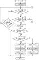
The 2 nd process is explained with reference to fig. 3. The control unit 52 executes the process 2 at predetermined intervals during the power-on period of the bicycle control device 50.
The control unit 52 detects the current shift stage in step S21, and proceeds to step S22. The current shift stage may be detected by the shift state detection device 40, or may be detected by the gear ratio r calculated based on the rotational speed N of the crank and the rotational speed V of the wheel. The control unit 52 determines in step S22 whether or not the target shift stage matches the current shift stage. Specifically, the control unit 52 compares the target shift stage updated in the 1 st process shown in fig. 2 with the shift stage corresponding to the operating state of the transmission 22 detected by the shift state detection device 40. When the target shift stage matches the current shift stage, the control unit 52 ends the process. If the target shift stage is different from the current shift stage, the control unit 52 proceeds to step S23.
In step S23, the controller 52 acquires the current crank rotation speed N, and proceeds to step S24. In step S24, the control unit 52 determines whether the rotation angle CA of the crank has reached the 1 st angle CA 1. The 1 st angle CA1 corresponds to the end of the crank 12A on the upstream side in the positive rotational direction in a predetermined range. The control unit 52 repeats the determination of step S24 until the 1 st angle CA1 is reached. If it is determined in step S24 that the angle reaches the 1 st angle CA1, the control unit 52 starts limiting the motor output TM in step S25, and proceeds to step S26. In step S25, the control unit 52 controls the motor 24 such that the motor output TM becomes the limit value DTM stored in the storage unit 54. In step S26, the control unit 52 starts the shifting operation of the transmission 22 so that the speed ratio r is changed to the target shift stage stored in the storage unit 54.
Next, the control unit 52 determines whether or not the 1 st time SA has elapsed in step S27. Specifically, the control unit 52 determines in step S27 whether or not the time after the start of the restriction of the motor output TM is equal to or longer than the 1 st time SA. The control unit 52 repeats the determination of step S27 until the 1 st time SA elapses. When determining that the 1 st time SA has elapsed, the control unit 52 ends the limitation of the motor output TM in step S28, executes a sub-flow of the learning process on the limit value DTM of the motor output TM and the 1 st time SA in step S29, and ends the present process.
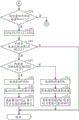
The learning process will be described with reference to fig. 4 and 5.
As shown in fig. 4, the controller 52 calculates the estimated rotational speed NA of the crank 12A in step S31, and then proceeds to step S32. The estimated rotation speed NA is calculated by multiplying the rotation speed N of the crank acquired in step S23 by the gear ratio r corresponding to the target shift stage updated in step S12. In step S32, the control unit 52 determines whether or not the manual driving force TA is equal to or greater than a predetermined value TAX.
When the manual driving force TA is less than the predetermined value TAX, the control unit 52 determines in step S33 whether or not the rotation amount DC of the crank 12A is equal to or greater than the predetermined amount DCA and whether or not the 2 nd time SB has elapsed. For example, when the time after the restriction of the motor output TM is ended in step S28 of fig. 3 is equal to or longer than the 2 nd time SB, it is determined that the 2 nd time SB has elapsed. The 2 nd time SB corresponds to, for example, a time sufficient for the rotation amount DC of the crank 12A to become equal to or more than the predetermined amount DCA when the bicycle 10 travels at the predetermined vehicle speed. When the rotation amount DC of the crank 12A is less than the predetermined amount DCA, the control unit 52 executes the determination process of step S32 again. When the rotation amount DC of the crank 12A is equal to or greater than the predetermined amount DCA, the control unit 52 ends the present process. The rotation amount DC of the crank 12A is, for example, the amount of change in the rotation angle CA of the crank after the restriction of the motor output TM is ended in step S28 of fig. 3. If the rider intentionally decreases the rotational speed N of the crank or stops pedaling, the human driving force TA tends to become less than the predetermined value TAX. When the manual driving force TA is less than the predetermined value TAX and the rotation amount DC of the crank 12A is equal to or greater than the predetermined amount DCA, the crank 12A rotates sufficiently after the execution of the shifting operation, but the manual driving force TA does not rise sufficiently, and therefore, it is determined that the determination of whether the shifting is appropriately performed is not correctly performed, and the processing is terminated. When the manual driving force TA is less than the predetermined value TAX, the rotation amount DC of the crank 12A is less than the predetermined amount DCA, and the 2 nd time SB has elapsed, it is determined whether or not the shift is properly performed, and the process is ended. If the rider intentionally decreases the crank rotation speed N, the rotation speed V of the wheel tends to be equal to or greater than the value obtained by multiplying the rotation speed N of the crank 12A by the gear ratio r, and therefore it becomes difficult to determine whether or not the gear shift is properly performed.
When it is determined in step S32 that the human power driving force TA is equal to or greater than the predetermined value TAX, the control unit 52 can determine that the gear shift is appropriately performed in step S35 by comparing the estimated rotational speed NA calculated in step S31 with the rotational speed N of the crank in step S34 and, when the estimated rotational speed NA matches the rotational speed N of the crank. If the state of the transmission 22 detected by the shift state detection device 40 at step S34 is a state corresponding to the target shift stage, the shift may be appropriately performed, and the process may proceed to step S35. At step S35, control unit 52 stores success determination information indicating that the gear shift is properly performed in storage unit 54, and proceeds to step S36.
In step S36, the control unit 52 determines whether or not the number of times the gear shift is appropriately performed is equal to or greater than the 2 nd number of times from the success determination information stored in the storage unit 54. In the present embodiment, the number of times the gear shift is appropriately performed is described as the appropriate gear shift number. When the appropriate number of shifts is less than the 2 nd number, the control unit 52 ends the process. When the appropriate number of gear shifts is equal to or greater than the 2 nd number, the control unit 52 determines whether or not the 1 st time SA is equal to or less than the predetermined value SY in step S37. When the 1 st time SA is equal to or less than the predetermined value SY, the control unit 52 proceeds to step S38.
In step S38, the control unit 52 calculates a limit value DTM of the motor output TM. Specifically, control unit 52 adds a predetermined value to current limit value DTM. Next, the control unit 52 executes the limiting process of the limit value DTM in step S39. Specifically, when the limit value DTM calculated in step S38 is equal to or greater than the predetermined value DTX1, the control unit 52 limits the limit value DTM to the predetermined value DTX 1. By limiting limit value DTM to be equal to or less than predetermined value DTX1, it is possible to suppress the shifting from being performed in a state where motor output TM is large. Next, in step S40, the control unit 52 updates the limit value DTM calculated in step S38 to a new limit value DTM, or in the case where the limiting process is performed in step S39, updates the predetermined value DTX1 to a new limit value DTM, initializes the appropriate number of gear shifts, and ends the process.
If it is determined in step S37 that the 1 st time SA is longer than the predetermined value SY, the control unit 52 proceeds to step S41 to calculate the 1 st time SA. Specifically, the control unit 52 subtracts a predetermined value from the current 1 st time SA. Next, the control unit 52 executes the limiting process for the 1 st time SA in step S42. Specifically, when the 1 st time SA calculated in step S41 is equal to or less than the predetermined value SY, the control unit 52 limits the 1 st time SA to the predetermined value SY. Next, in step S43, the control unit 52 updates the 1 st time SA calculated in step S41 to a new 1 st time SA, or updates the predetermined value SY to a new 1 st time SA when the limiting process is performed in step S42, initializes information on the appropriate number of gear shifts, and ends the process.
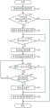
When it is estimated in step S34 that the rotation speed NA does not match the crank rotation speed N, the controller 52 proceeds to step S44 of fig. 5, and determines in step S44 whether or not the rotation amount DC of the crank 12A is equal to or greater than a predetermined amount DCA. When the rotation amount DC of the crank 12A is less than the predetermined amount DCA, the control unit 52 executes the determination process of step S32 in fig. 4 again. When the rotation amount DC of the crank 12A is equal to or greater than the predetermined amount DCA, the control unit 52 proceeds to step S45.
If it is determined in step S34 that the estimated rotation speed NA does not match the crank rotation speed N and it is determined in step S44 that the rotation amount DC of the crank 12A is equal to or greater than the predetermined amount DCA, the controller 52 can determine that the gear shift is not properly performed, and therefore, the process proceeds to step S45. If the state of the transmission 22 detected by the shift state detection device 40 is not in accordance with the target shift stage in step S34, the shift may be executed as a failure, and the process may proceed to step S45. At step S45, control unit 52 stores failure determination information indicating that the gear shift has not been properly performed in storage unit 54, and proceeds to step S46.
In step S46, the control unit 52 determines whether or not the number of times the gear shift is not properly performed is equal to or greater than the 1 st time, based on the failure determination information stored in the storage unit 54. In the present embodiment, the number of times that the gear shift is not properly performed is described as the number of times that the gear shift is not properly performed. When the inappropriate number of times of shifting is less than the 1 st number of times, the control unit 52 ends the process. When the inappropriate number of times of shifting is equal to or greater than the 1 st number of times, the control unit 52 determines in step S47 whether or not the limit value DTM is equal to or less than a predetermined value DTX 2. When limit value DTM is equal to or less than predetermined value DTX2, control unit 52 proceeds to step S48. The predetermined value DTX2 is selected to be "0", for example.
The control unit 52 calculates the 1 st time SA in step S48. Specifically, the control unit 52 adds a predetermined value to the current 1 st time SA. Next, the control unit 52 executes the limiting process for the 1 st time SA in step S49. Specifically, when the 1 st time SA calculated in step S48 is equal to or greater than the upper limit value SC, the control unit 52 limits the 1 st time SA to the upper limit value SC. Next, in step S50, the control unit 52 updates the 1 st time SA calculated in step S48 to the new 1 st time SA, or in step S49, if the limiting process is performed, updates the upper limit value SC to the new 1 st time SA, initializes information on the number of inappropriate gear shifts, and ends the process.
When the control unit 52 determines in step S47 that the limit value DTM is greater than the predetermined value DTX2, the control unit calculates in step S51 the limit value DTM of the motor output TM. Specifically, control unit 52 subtracts a predetermined value from current limit value DTM. Next, the control unit 52 executes the limiting process of the limit value DTM in step S52. Specifically, when the limit value DTM calculated in step S51 is equal to or less than the predetermined value DTX2, the control unit 52 limits the limit value DTM to the predetermined value DTX 2. When limit value DTM is set to "0", motor output TM is "0" at time 1 SA. Next, in step S53, the control unit 52 updates the limit value DTM calculated in step S51 to a new limit value DTM, or in the case where the limiting process is performed in step S53, updates the predetermined value DTX2 to a new limit value DTM, initializes information on the number of inappropriate gear shifts, and ends the process.
(embodiment 2)
A bicycle control device 50 according to embodiment 2 will be explained with reference to fig. 1 and 6. In embodiment 2, the same reference numerals as those in embodiment 1 are given to the same portions as those in embodiment 1. In embodiment 2, the content of the 1 st process and the configuration are the same as those of embodiment 1 except for the 2 nd process, and therefore, the description of the same portions will be omitted and only different portions will be described.
The control unit 52 lowers the output of the motor 24 when the transmission 22 performs the shifting operation, and ends the control of lowering the output of the motor 24 before the predetermined period SZ elapses, the shifting operation is completed, or the speed ratio r changes, when the predetermined period SZ elapses. When the predetermined period SZ has elapsed and the speed change operation or the change of the speed ratio r has not been completed, the control unit 52 ends the control of decreasing the output of the motor 24. The predetermined period SZ is set independently in accordance with the gear ratio to be changed. The predetermined period SZ is stored in the storage unit 54. The predetermined period SZ may be measured by a timer or may be measured based on the rotation angle CA of the crank.
The 2 nd process is explained with reference to fig. 6. The control unit 52 executes the process 2 at predetermined intervals during the power-on period of the bicycle control device 50.
The control unit 52 detects the current shift stage in step S21, and proceeds to step S22. The control unit 52 determines in step S22 whether or not the target shift stage matches the current shift stage. When the target shift stage matches the current shift stage, the control unit 52 ends the process. If the target shift stage is different from the current shift stage, the control unit 52 proceeds to step S23.
In step S23, the controller 52 acquires the current crank rotation speed N, and proceeds to step S24. In step S24, the control unit 52 determines whether the rotation angle CA of the crank has reached the 1 st angle CA 1. The controller 52 repeats the determination of step S24 until the 1 st angle CA1 is reached. If it is determined in step S24 that the angle reaches the 1 st angle CA1, the control unit 52 starts limiting the motor output TM in step S25, and proceeds to step S26. In step S26, the control unit 52 controls the motor 24 such that the motor output TM becomes the limit value DTM stored in the storage unit 54. In step S26, the control unit 52 starts the shifting operation of the transmission 22 so that the speed ratio r is changed to the target shift stage set in step S12.
Next, the control unit 52 proceeds to step S61 to determine whether or not an appropriate gear shift is performed. The control unit 52 can determine that an appropriate shift has been performed when the operating state of the transmission 22 detected based on the output of the shift state detection device 40 matches the operating state of the transmission 22 corresponding to the target shift stage. The control unit 52 can determine that the appropriate shift is performed when the crank rotation speed N matches the estimated crank rotation speed N calculated from the crank rotation speed N before the shift acquired in step S23 and the gear ratio r corresponding to the target shift stage. When determining that the appropriate gear shift has not been performed, the control unit 52 proceeds to step S62 to determine whether or not a predetermined period SZ has elapsed. For example, when the elapsed time from the start of the gear shift operation of the transmission 22 in step S26 is equal to or longer than the predetermined period SZ, the control unit 52 determines that the predetermined period SZ has elapsed. When the predetermined period SZ has not elapsed, the control unit 52 performs the determination of step S61 again. When it is determined in step S62 that the predetermined period SZ has elapsed, the control unit 52 ends the gear shift operation in step S63 and ends the limitation of the motor output TM in step S28. In this case, when the predetermined period SZ has elapsed without the completion of the gear shift, the gear shift operation is interrupted. The predetermined period SZ may be a period from the time when the 1 st shift operation is started or the time when the motor output TM is started to be limited to the time when the crank 12A rotates to a predetermined angle. The predetermined angle is selected to be 180 degrees or less, for example, 90 degrees or less. The predetermined angle is selected to be 20 degrees or more, preferably 30 degrees or more.
If it is determined in step S61 that the appropriate gear shift has been performed, the control unit 52 ends the restriction of the motor output TM in step S28. In this case, the limitation of the motor output TM is ended before the predetermined period SZ.
(modification example)
The above description of the embodiments is an example of the manner in which the bicycle control device according to the present invention can be obtained, and is not intended to limit the manner. The bicycle control device according to the present invention can be obtained by combining the following modifications of the above embodiments and at least 2 modifications that are not mutually inconsistent. In the following modifications, the same reference numerals as in the embodiments are given to the same portions as those of the embodiments, and the description thereof is omitted.
The bicycle control device 50 according to modification 1 may omit the steps S44 to S53 from the learning process shown in fig. 4 and 5 of embodiment 1. In this case, if the determination at step S34 is negative, the control unit 52 ends the process.
The bicycle control device 50 according to modification 2 may omit steps S35 to S43 from the learning process shown in fig. 4 and 5 of embodiment 1. In this case, if the determination is affirmative in step S34, the control unit 52 ends the process.
In the bicycle control device 50 according to modification 3, in steps S34 and S61 of the respective embodiments and modifications, when the speed ratio r corresponding to the target shift stage stored in the storage unit 54 matches the ratio of the rotational speed V of the wheel to the current rotational speed N of the crank, the control unit 52 can determine that the shift is appropriately performed and move to the next step. The control unit 52 can change at least one of the limit value DTM and the 1 st time SA based on the determination result of whether or not the change of the speed ratio r is appropriately performed. In this case, step S31 may be omitted in embodiment 1 and the modifications including step S31.
In the bicycle control device 50 according to modification 4, the information on the target shift stage may be replaced with the information on the target speed ratio r in each of the embodiment and the modifications. The control unit 52 detects the current gear ratio r in step S21, and moves to step S22. The current gear ratio r is calculated based on the rotational speed N of the crank and the rotational speed V of the wheel. The control unit 52 determines in step S22 whether or not the target speed ratio r matches the current speed ratio r. Specifically, the control unit 52 compares the information about the speed ratio r corresponding to the target shift stage updated in the 1 st process shown in fig. 2 with the speed ratio r calculated from the ratio of the rotational speed V of the wheels to the rotational speed N of the crank. In step S22, the control unit 52 ends the process when the target speed ratio r matches the current speed ratio r. If the target speed ratio r is different from the current speed ratio r in step S22, the control unit 52 proceeds to step S23. In step S26, the control unit 52 starts the shifting operation of the transmission 22 so that the speed ratio r is changed to the target speed ratio r set in step S12.
In the bicycle control device 50 according to modification 5, when the speed ratio r is reduced in the 1 st shift operation according to embodiment 1 and modifications 1 to 4, the 2 nd shift operation may include all shift operations that are executed after the 1 st shift operation and are changed so that the speed ratio r is reduced. In addition, when the speed ratio r is increased in the 1 st shift operation, the 2 nd shift operation may include all shift operations that are executed after the 1 st shift operation and are changed so as to increase the speed ratio r. In this case, the following contents are stored in the storage unit 54, with the following distinction: the number of times the gear shift is appropriately performed when the gear ratio r is made large, the number of times the gear shift is not appropriately performed when the gear ratio r is made large, the 1 st time SA when the gear ratio r is made large, the limit value DTM when the gear ratio r is made large, the number of times the gear shift is appropriately performed when the gear ratio r is made small, the number of times the gear shift is not appropriately performed when the gear ratio r is made small, the 1 st time SA when the gear ratio r is made small, and the limit value DTM when the gear ratio r is made small.
In the bicycle control device 50 according to the 6 th modification example, in the 1 st shift operation according to the 1 st embodiment and the 1 st to 4 th modifications examples, when the transmission 22 changes the speed ratio r from the 1 st speed ratio r1 to the 2 nd speed ratio r2, the 2 nd shift operation includes all shift operations that are executed after the 1 st shift operation and in which the transmission 22 changes the speed ratio r from the 1 st speed ratio r1 to the 2 nd speed ratio r 2. In this case, the following combinations are distinguished and stored in the storage unit 54: the combination of the number of times the gear ratio r is changed properly, the number of times the gear ratio r is not changed properly, the 1 st time SA, and the limit value DTM, and the gear ratio r before and after the change.
The bicycle control device 50 according to modification 7 may omit the processing of steps S35 and S36 in the learning process according to embodiment 1 and the learning process according to the modifications that do not include modification 2. In this case, if the determination at step S34 in fig. 4 is affirmative, the controller 52 proceeds to step S37. In this case, when it is determined that the shift is performed once, at least one of the limit value DTM and the 1 st time SA in the next and subsequent shift operations is changed.
In the learning process of embodiment 1 and the learning process of each modification example not including modification example 1, the processes of step S45 and step S46 may be omitted. In this case, if the determination at step S46 in fig. 5 is affirmative, the controller 52 proceeds to step S47. In this case, when it is determined that the first shift is not properly performed, at least one of the limit value DTM and the 1 st time SA in the next and subsequent shift operations is changed.
In the learning process of embodiment 1 and the learning process of each modification not including modification 2, steps S37 and S41 to S43 in fig. 4 may be omitted and time 1 SA may not be changed. In this case, if the determination in step S36 is affirmative, the controller 52 proceeds to step S38. In the learning process of embodiment 1 and the learning process of each modification example not including modification example 2, steps S37 to S40 may be omitted and limit value DTM may not be changed. In this case, if the determination in step S36 is affirmative, the controller 52 proceeds to step S41.
In the learning process of embodiment 1 and the learning process of each modification example not including modification example 1, steps S47 and S51 to S53 in fig. 5 may be omitted, and the limit value DTM may not be changed. In this case, if the determination in step S46 is affirmative, the controller 52 proceeds to step S48. In the learning process of embodiment 1 and the learning process of each modification example not including modification example 1, steps S47 to S50 may be omitted and time 1 SA may not be changed. In this case, if the determination in step S46 is affirmative, the controller 52 proceeds to step S51.
In the learning process of embodiment 1 and the learning processes of the modifications including steps S38 to S40 and steps S41 to S43, both of limit value DTM and 1 st time SA may be changed when the gear shift is appropriately performed. If the determination is affirmative in step S36 of fig. 4, or if the determination is affirmative in step S34 in the modification in which steps S35 and S36 are omitted, the control unit 52 omits the determination processing in step S37 and executes the processing in steps S38 to S40 and steps S41 to S43.
In the learning process of embodiment 1 and the learning processes of the modifications including steps S48 to S50 and steps S51 to S53, both of limit value DTM and 1 st time SA may be changed when the gear shift is not appropriately performed. If the determination is affirmative in step S46 of fig. 5, or if the determination is affirmative in step S44 in the modification in which steps S45 and S46 are omitted, the control unit 52 omits the determination processing in step S47 and executes the processing in steps S48 to S50 and steps S51 to S53.
In the process 2 of each embodiment, the gear shift operation of the transmission 22 may be started before the restriction of the motor output TM is started. Further, the restriction of the motor output TM and the start of the gear shift operation of the transmission 22 may be performed simultaneously.
In the process 2 of each embodiment, the process of step S24 may be omitted. In this case, if it is determined in step S22 that the target shift stage does not match the current shift stage, the control unit 52 may immediately start the restriction of the motor output TM and the shift operation of the transmission 22.
The process 2 may be executed in an automatic shift in which the control unit 52 automatically controls the transmission 22 to shift gears in response to one or more sensors mounted to the bicycle 10. The one or more sensors mounted to the bicycle 10 include at least one of a torque sensor, a vehicle speed sensor, and a cadence sensor. The control unit 52 determines whether or not there is a shift request in response to signals from one or more sensors mounted on the bicycle 10 and a control program for automatic shifting stored in the storage unit 54.
The transmission 22 may be manually shifted. In this case, the operation unit 26 and the transmission 22 are connected by a cable. The control unit 52 sets a gear shift request in accordance with an output of the detection unit for detecting an operation of the operation unit 26, and controls the motor 24.
Description of the reference numerals
10 … bicycle, 12A … crank, 22 … speed changer, 24 … motor, 50 … bicycle control device, 52 … control part.
Claims (22)
1. A bicycle control device is characterized by comprising a control unit for controlling a motor for assisting the propulsion of a bicycle,
the control unit may decrease the output of the motor to a limit value or less when a transmission that changes a gear ratio of the bicycle performs a shifting operation, and may change at least one of the limit value of the output of the motor and a time period for which the output of the motor decreases when the transmission performs the shifting operation, in accordance with at least one of an operating state of the transmission during the shifting operation and a parameter of the bicycle that changes when the transmission performs the shifting operation.
2. The bicycle control apparatus of claim 1,
the shifting actions include a1 st shifting action, a2 nd shifting action executed after the 1 st shifting action,
the control unit varies at least one of the limit value of the output of the motor and the time for which the output of the motor is reduced when the 2 nd shift operation is performed, in accordance with at least one of the operating state of the transmission in the 1 st shift operation and the parameter of the bicycle that changes when the transmission performs the 1 st shift operation, from at least one of the limit value of the output of the motor and the time for which the output of the motor is reduced when the 1 st shift operation is performed.
3. The bicycle control apparatus of claim 2,
in the case where the speed ratio is reduced in the 1 st shift operation, the 2 nd shift operation includes all of the shift operations that are executed after the 1 st shift operation and are changed so as to reduce the speed ratio.
4. The bicycle control apparatus of claim 2,
in the case where the speed ratio is increased in the 1 st shifting operation, the 2 nd shifting operation includes all of the shifting operations that are executed after the 1 st shifting operation and are changed so as to increase the speed ratio.
5. The bicycle control apparatus of claim 2,
the 2 nd shift operation includes all of the shift operations performed after the 1 st shift operation.
6. The bicycle control apparatus of claim 2,
in the case where the transmission changes the speed ratio from the 1 st speed ratio to the 2 nd speed ratio in the 1 st shift operation,
the 2 nd shift operation includes all of the shift operations that are executed after the 1 st shift operation and in which the transmission changes the speed ratio from the 1 st speed ratio to the 2 nd speed ratio.
7. The bicycle control apparatus of claim 2,
the control unit may be configured to, if the transmission performs the 1 st shift operation, and the 1 st shift operation is not completed or the speed ratio is not changed within a predetermined period, perform at least one of a decrease in the limit value of the output of the motor and an increase in time for which the output of the motor decreases when the transmission performs the 2 nd shift operation, as compared to when the transmission performs the 1 st shift operation.
8. The bicycle control apparatus of claim 7,
the control unit may decrease the limit value of the output of the motor when the transmission performs the 2 nd shift operation as compared with a case where the transmission performs the 1 st shift operation if the transmission performs the 1 st shift operation in a state where the output of the motor is not decreased to a predetermined value and the 1 st shift operation is not completed or the transmission ratio is not changed within the predetermined period,
if the transmission performs the 1 st shift operation and the 1 st shift operation is not completed or the transmission ratio is not changed within the predetermined period in a state where the output of the motor is reduced to a predetermined value, a time period for reducing the output of the motor is increased when the transmission performs the 2 nd shift operation as compared with a case where the transmission performs the 1 st shift operation.
9. The bicycle control apparatus of claim 7,
the control unit may be configured to, if the transmission performs the 1 st shift operation, perform at least one of a decrease in the limit value of the output of the motor and an increase in time for decreasing the output of the motor when the transmission performs the 2 nd shift operation, as compared to a case where the transmission performs the 1 st shift operation, if the number of times the 1 st shift operation is not completed or the number of times the transmission ratio is not changed reaches the 1 st time within the predetermined period.
10. The bicycle control apparatus of claim 2,
the control unit may be configured to, if the transmission performs the 1 st shift operation, complete the 1 st shift operation or change the speed ratio within a predetermined period, perform at least one of an increase in the limit value of the output of the motor and a decrease in the time for which the output of the motor decreases when the transmission performs the 2 nd shift operation, as compared to when the transmission performs the 1 st shift operation.
11. The bicycle control apparatus of claim 7,
the control unit may be configured to, if the transmission performs the 1 st shift operation, complete the 1 st shift operation or change the speed ratio within the predetermined period, perform at least one of an increase in the limit value of the output of the motor and a decrease in the time for which the output of the motor decreases when the transmission performs the 2 nd shift operation, as compared to when the transmission performs the 1 st shift operation.
12. The bicycle control apparatus of claim 10,
the control unit may be configured such that the transmission performs the 1 st shift operation, and the 1 st shift operation is completed or the transmission ratio is changed within the predetermined period in a state where a time for decreasing the output of the motor is longer than a predetermined value, and in the case where the transmission performs the 2 nd shift operation, the time for decreasing the output of the motor is reduced as compared with a case where the transmission performs the 1 st shift operation,
in the case where the 1 st shift operation is performed by the transmission, the 1 st shift operation is completed or the transmission ratio is changed within the predetermined period in a state where a time for which the output of the motor is reduced is equal to or less than a predetermined value, and in the case where the limit value of the output of the motor is increased when the transmission performs the 2 nd shift operation as compared with a case where the transmission performs the 1 st shift operation.
13. The bicycle control apparatus of claim 10,
the control unit may be configured to, when the transmission performs the 1 st shift operation, increase at least one of the limit value of the output of the motor and the time for decreasing the output of the motor when the transmission performs the 2 nd shift operation when the number of times the 1 st shift operation is completed or the number of times the transmission ratio is changed reaches the 2 nd time within the predetermined period, as compared with a case where the transmission performs the 1 st shift operation.
14. The bicycle control apparatus of claim 1, wherein the bicycle parameter comprises a rotational speed of a crank of the bicycle.
15. A bicycle control device, characterized in that,
the bicycle control device is provided with a control part for controlling a motor for assisting the propulsion of a bicycle,
the control unit reduces the output of the motor when a transmission that changes a gear ratio of the bicycle performs a shifting operation, ends the control to reduce the output of the motor before a predetermined period elapses and the shifting operation is completed or the gear ratio is changed, and ends the control to reduce the output of the motor when the predetermined period elapses and the shifting operation or the change of the gear ratio is not completed.
16. The bicycle control apparatus of claim 15,
the predetermined period is set independently corresponding to the speed ratio to be changed.
17. The bicycle control apparatus according to any one of claims 7-16,
the control unit determines whether or not the gear ratio has changed based on a rotational speed of a crank of the bicycle and a rotational speed of a wheel of the bicycle.
18. The bicycle control apparatus of claim 17,
the control unit executes control corresponding to determination based on the rotation speed of the crank of the bicycle only when the manual driving force input to the crank of the bicycle is equal to or greater than a predetermined value.
19. The bicycle control apparatus according to any one of claims 1-15,
the control unit controls an electric actuator that causes the transmission to perform the shifting operation.
20. The bicycle control apparatus of claim 19,
the control unit operates the transmission when a rotation angle of a crank of the bicycle is within a predetermined range,
the predetermined range includes a top dead center or a bottom dead center of a crank of the bicycle.
21. A method of controlling a bicycle, the method of controlling a bicycle that controls a motor for assisting propulsion of the bicycle, the method of controlling the bicycle characterized by,
when a transmission that changes a gear ratio of the bicycle performs a shifting operation, an output of the motor is reduced to a limit value or less, and at least one of the limit value of the output of the motor and a time period during which the output of the motor is reduced when the transmission performs the shifting operation is changed in accordance with at least one of an operating state of the transmission after the shifting operation and a parameter of the bicycle that changes as a result of the transmission performing the shifting operation.
22. A method of controlling a bicycle, the method of controlling a bicycle that controls a motor for assisting propulsion of the bicycle, the method of controlling the bicycle characterized by,
the control unit is configured to reduce the output of the motor when a gear shifting operation is performed by a transmission that changes a gear ratio of the bicycle, to end the control to reduce the output of the motor before a predetermined period elapses, when the gear shifting operation is completed or the gear ratio is changed before the predetermined period elapses, and to end the control to reduce the output of the motor when the predetermined period elapses and the gear shifting operation or the change of the gear ratio is not completed.
Applications Claiming Priority (2)
| Application Number | Priority Date | Filing Date | Title |
|---|---|---|---|
| JP2017015273A JP6705760B2 (en) | 2017-01-31 | 2017-01-31 | Bicycle control device and bicycle control method |
| JP2017-015273 | 2017-01-31 |
Publications (2)
| Publication Number | Publication Date |
|---|---|
| CN108372900A CN108372900A (en) | 2018-08-07 |
| CN108372900B true CN108372900B (en) | 2020-05-05 |
Family
ID=62843121
Family Applications (1)
| Application Number | Title | Priority Date | Filing Date |
|---|---|---|---|
| CN201810077258.XA Active CN108372900B (en) | 2017-01-31 | 2018-01-26 | Bicycle control device and bicycle control method |
Country Status (5)
| Country | Link |
|---|---|
| US (2) | US11059537B2 (en) |
| JP (1) | JP6705760B2 (en) |
| CN (1) | CN108372900B (en) |
| DE (1) | DE102018100918A1 (en) |
| TW (1) | TWI724268B (en) |
Families Citing this family (8)
| Publication number | Priority date | Publication date | Assignee | Title |
|---|---|---|---|---|
| JP7048388B2 (en) * | 2018-03-29 | 2022-04-05 | 株式会社シマノ | Control device for human-powered vehicles |
| JP7156908B2 (en) * | 2018-10-31 | 2022-10-19 | 株式会社シマノ | Controller and detector |
| US10875604B2 (en) * | 2019-03-07 | 2020-12-29 | Shimano Inc. | Shifting system for human-powered vehicle |
| JP7324694B2 (en) * | 2019-11-25 | 2023-08-10 | 株式会社シマノ | Discrimination device for human-powered vehicle and control device for human-powered vehicle |
| IT201900024595A1 (en) * | 2019-12-18 | 2021-06-18 | Rosario Aliperti | BICYCLE WITH AUTOMATIC TRANSMISSION EXCLUSIVELY HUMAN PROPULSION |
| DE102020132627A1 (en) * | 2019-12-18 | 2021-06-24 | Shimano Inc. | CONTROL DEVICE FOR A MUSCLE POWERED VEHICLE AND POWER TRANSFER SYSTEM |
| NL2025379B1 (en) * | 2020-04-20 | 2021-12-13 | Jonan Midas Carlier Ties | SHIFT AND CYCLE |
| DE202022002874U1 (en) | 2022-09-23 | 2023-10-18 | Porsche Ebike Performance Gmbh | Device for changing gears on a bicycle |
Family Cites Families (26)
| Publication number | Priority date | Publication date | Assignee | Title |
|---|---|---|---|---|
| JPS5496158A (en) | 1978-01-07 | 1979-07-30 | Dainippon Screen Mfg | Needle selector of automatic weft nitting machine |
| US6047230A (en) * | 1997-02-27 | 2000-04-04 | Spencer; Marc D. | Automatic bicycle transmission |
| JP3717076B2 (en) * | 2003-03-11 | 2005-11-16 | 株式会社シマノ | Shift control device for motorcycle |
| JP3680277B2 (en) * | 2003-10-10 | 2005-08-10 | トヨタ自動車株式会社 | Control device for hybrid vehicle |
| JP2005313748A (en) * | 2004-04-28 | 2005-11-10 | Shimano Inc | Speed-change controller for cycles |
| DE202009018521U1 (en) * | 2008-12-11 | 2012-01-18 | Robert Bosch Gmbh | Hybrid drive for an electric bicycle |
| CN201849627U (en) * | 2010-03-31 | 2011-06-01 | 重庆港鑫机械制造有限公司 | Electric bicycle |
| JP5247863B2 (en) * | 2011-08-29 | 2013-07-24 | 株式会社シマノ | Bicycle control device |
| JP5566975B2 (en) * | 2011-08-29 | 2014-08-06 | 株式会社シマノ | Bicycle control device |
| JP5237421B2 (en) * | 2011-08-29 | 2013-07-17 | 株式会社シマノ | Bicycle control device |
| JP5276735B1 (en) * | 2012-04-06 | 2013-08-28 | 株式会社シマノ | Bicycle control device |
| TW201402399A (en) * | 2012-07-10 | 2014-01-16 | J D Components Co Ltd | Power assisting bicycle gearshift system with pedaling position as judgment basis |
| JP6218172B2 (en) * | 2012-12-17 | 2017-10-25 | ヤマハ発動機株式会社 | Drive unit and battery-assisted bicycle |
| US9243692B2 (en) * | 2013-02-19 | 2016-01-26 | Sram, Llc | Electric bicycle transmission |
| DE102013220541B4 (en) * | 2013-10-11 | 2015-05-21 | Continental Automotive Gmbh | A method for detecting a shift of a gearbox of a bicycle and method for controlling the power of an auxiliary drive of a bicycle |
| JP5575968B1 (en) * | 2013-10-29 | 2014-08-20 | 株式会社シマノ | Bicycle control device |
| US10155567B2 (en) * | 2014-10-07 | 2018-12-18 | Shimano Inc. | Bicycle shifting control apparatus |
| JP6321558B2 (en) | 2015-01-15 | 2018-05-09 | 株式会社シマノ | Bicycle assist device control device and bicycle assist device |
| JP6321557B2 (en) | 2015-01-15 | 2018-05-09 | 株式会社シマノ | Bicycle assist device control device and bicycle assist device |
| CN106143772B (en) * | 2015-03-26 | 2019-04-09 | 久鼎金属实业股份有限公司 | Cooperate the bicycle continuous variable speed speed ratio control method of planetary gear set |
| US9573654B2 (en) * | 2015-04-28 | 2017-02-21 | Shimano Inc. | Bicycle controller |
| DE102016209570B3 (en) * | 2016-06-01 | 2017-08-24 | Robert Bosch Gmbh | Control method and control unit for adjusting a speed of the pushing aid of an electric bicycle |
| TWM530282U (en) * | 2016-07-15 | 2016-10-11 | Paltorc Inc | Smart crank and man power driving device with auxiliary power thereof |
| IT201600080244A1 (en) * | 2016-07-29 | 2018-01-29 | Campagnolo Srl | Method of controlling an engine of a derailleur of an electronic bicycle gearshift and component adapted to perform this method |
| DE102016218374B3 (en) * | 2016-09-23 | 2018-02-22 | Robert Bosch Gmbh | Control method and devices for pushing aid for an electric bicycle |
| JP6670734B2 (en) * | 2016-10-31 | 2020-03-25 | 株式会社シマノ | Bicycle control device and bicycle control system including the same |
-
2017
- 2017-01-31 JP JP2017015273A patent/JP6705760B2/en active Active
-
2018
- 2018-01-17 TW TW107101639A patent/TWI724268B/en active
- 2018-01-17 DE DE102018100918.6A patent/DE102018100918A1/en active Pending
- 2018-01-18 US US15/874,670 patent/US11059537B2/en active Active
- 2018-01-26 CN CN201810077258.XA patent/CN108372900B/en active Active
-
2021
- 2021-06-10 US US17/344,200 patent/US11807337B2/en active Active
Also Published As
| Publication number | Publication date |
|---|---|
| US20210300499A1 (en) | 2021-09-30 |
| US11059537B2 (en) | 2021-07-13 |
| CN108372900A (en) | 2018-08-07 |
| JP2018122666A (en) | 2018-08-09 |
| US11807337B2 (en) | 2023-11-07 |
| DE102018100918A1 (en) | 2018-08-02 |
| TW201829247A (en) | 2018-08-16 |
| US20180215432A1 (en) | 2018-08-02 |
| JP6705760B2 (en) | 2020-06-03 |
| TWI724268B (en) | 2021-04-11 |
Similar Documents
| Publication | Publication Date | Title |
|---|---|---|
| CN108372900B (en) | Bicycle control device and bicycle control method | |
| TWI744395B (en) | Bicycle control device and bicycle control system containing the device | |
| CN108001608B (en) | Bicycle control device and bicycle control system including the same | |
| TWI735785B (en) | Bicycle control device | |
| CN103359251B (en) | Bicycle control apparatus and bicycle control method | |
| TWI823965B (en) | Variable speed control system for human-driven vehicles | |
| TW201313547A (en) | Bicycle drive apparatus | |
| JP2019172226A (en) | Control device for man power drive vehicle | |
| CN114435526A (en) | Control device for human-powered vehicle | |
| JP2023087060A (en) | Control device for human-powered vehicle | |
| JP6916131B2 (en) | Control device | |
| JP7324646B2 (en) | Control device for man-powered vehicles | |
| TW202220896A (en) | Human-powered vehicle control device | |
| JP2021107227A (en) | Control device for bicycle | |
| CN114684311A (en) | Control device for human-powered vehicle | |
| JP7369531B2 (en) | Control device for human-powered vehicles | |
| JP6756887B2 (en) | Bicycle control device and bicycle control system including this | |
| JP6759436B2 (en) | Bicycle control device and bicycle control system including this | |
| TWI831960B (en) | Control device for human driven vehicles | |
| JP2022188706A (en) | Control device for man-powered vehicle | |
| JP2022188704A (en) | Control device for man-powered vehicle | |
| JP2021062834A (en) | Control device for man-powered drive vehicle | |
| JP2019206251A (en) | Control device for man-power drive vehicle and drive device for man-power drive vehicle |
Legal Events
| Date | Code | Title | Description |
|---|---|---|---|
| PB01 | Publication | ||
| PB01 | Publication | ||
| SE01 | Entry into force of request for substantive examination | ||
| SE01 | Entry into force of request for substantive examination | ||
| GR01 | Patent grant | ||
| GR01 | Patent grant |