CN107911050B - Compensation method for detecting position of permanent magnet synchronous motor rotor by high-frequency injection method - Google Patents
Compensation method for detecting position of permanent magnet synchronous motor rotor by high-frequency injection method Download PDFInfo
- Publication number
- CN107911050B CN107911050B CN201711195542.9A CN201711195542A CN107911050B CN 107911050 B CN107911050 B CN 107911050B CN 201711195542 A CN201711195542 A CN 201711195542A CN 107911050 B CN107911050 B CN 107911050B
- Authority
- CN
- China
- Prior art keywords
- theta
- rotor position
- permanent magnet
- synchronous motor
- magnet synchronous
- Prior art date
- Legal status (The legal status is an assumption and is not a legal conclusion. Google has not performed a legal analysis and makes no representation as to the accuracy of the status listed.)
- Active
Links
- 238000000034 method Methods 0.000 title claims abstract description 77
- 238000002347 injection Methods 0.000 title claims abstract description 70
- 239000007924 injection Substances 0.000 title claims abstract description 70
- 230000001360 synchronised effect Effects 0.000 title claims abstract description 60
- 238000001514 detection method Methods 0.000 claims abstract description 35
- 238000010586 diagram Methods 0.000 claims description 10
- 238000002474 experimental method Methods 0.000 claims description 9
- 230000003068 static effect Effects 0.000 abstract description 5
- 230000000694 effects Effects 0.000 description 7
- 230000000052 comparative effect Effects 0.000 description 4
- 238000005516 engineering process Methods 0.000 description 4
- 238000004364 calculation method Methods 0.000 description 2
- 238000004458 analytical method Methods 0.000 description 1
- 230000010355 oscillation Effects 0.000 description 1
- 238000012827 research and development Methods 0.000 description 1
- 239000000243 solution Substances 0.000 description 1
- 238000011895 specific detection Methods 0.000 description 1
- 238000012360 testing method Methods 0.000 description 1
Images


Classifications
-
- H—ELECTRICITY
- H02—GENERATION; CONVERSION OR DISTRIBUTION OF ELECTRIC POWER
- H02P—CONTROL OR REGULATION OF ELECTRIC MOTORS, ELECTRIC GENERATORS OR DYNAMO-ELECTRIC CONVERTERS; CONTROLLING TRANSFORMERS, REACTORS OR CHOKE COILS
- H02P6/00—Arrangements for controlling synchronous motors or other dynamo-electric motors using electronic commutation dependent on the rotor position; Electronic commutators therefor
- H02P6/14—Electronic commutators
- H02P6/16—Circuit arrangements for detecting position
- H02P6/18—Circuit arrangements for detecting position without separate position detecting elements
- H02P6/183—Circuit arrangements for detecting position without separate position detecting elements using an injected high frequency signal
-
- H—ELECTRICITY
- H02—GENERATION; CONVERSION OR DISTRIBUTION OF ELECTRIC POWER
- H02P—CONTROL OR REGULATION OF ELECTRIC MOTORS, ELECTRIC GENERATORS OR DYNAMO-ELECTRIC CONVERTERS; CONTROLLING TRANSFORMERS, REACTORS OR CHOKE COILS
- H02P2203/00—Indexing scheme relating to controlling arrangements characterised by the means for detecting the position of the rotor
- H02P2203/11—Determination or estimation of the rotor position or other motor parameters based on the analysis of high-frequency signals
-
- H—ELECTRICITY
- H02—GENERATION; CONVERSION OR DISTRIBUTION OF ELECTRIC POWER
- H02P—CONTROL OR REGULATION OF ELECTRIC MOTORS, ELECTRIC GENERATORS OR DYNAMO-ELECTRIC CONVERTERS; CONTROLLING TRANSFORMERS, REACTORS OR CHOKE COILS
- H02P2207/00—Indexing scheme relating to controlling arrangements characterised by the type of motor
- H02P2207/05—Synchronous machines, e.g. with permanent magnets or DC excitation
Landscapes
- Engineering & Computer Science (AREA)
- Power Engineering (AREA)
- Control Of Motors That Do Not Use Commutators (AREA)
Abstract
The invention discloses a compensation method for detecting the position of a permanent magnet synchronous motor rotor by a high-frequency injection method, which comprises the following steps: s10), before detection, the linear interpolation table θ is determined in advancecmp=f(θ0) The linear interpolation table thetacmp=f(θ0) The characteristic is the inherent characteristic of the second harmonic of the permanent magnet synchronous motor; s20), during detection, according to the linear interpolation table thetacmp=f(θ0) For the theta0Performing dynamic open loop compensation to eliminate second harmonic generated during high frequency injection detection, wherein theta iscmpCompensating the angle for rotor position, said theta0Estimating an angle for the rotor position; the invention can obviously reduce the problem of second harmonic in the high-frequency injection method, effectively improve the precision of detecting the position of the permanent magnet synchronous motor rotor by adopting the high-frequency injection method, and obviously improve the static and dynamic operation performance of the whole high-frequency injection method detection system.
Description
Technical Field
The invention relates to the field of detection of the position of a rotor controlled by a permanent magnet synchronous motor, in particular to a compensation method for detecting the position of the rotor of the permanent magnet synchronous motor by a high-frequency injection method.
Background
The permanent magnet synchronous motor has the advantages of high efficiency, small volume, low noise and the like, so the permanent magnet synchronous motor is widely applied to the fields of household appliances, electric automobiles and the like. Compared with the traditional technology, the sensorless control technology of the permanent magnet synchronous motor omits a position sensor, reduces the hardware cost and improves the system reliability.
In a plurality of sensorless detection technologies, a high-frequency injection method utilizes the salient pole characteristic of a permanent magnet synchronous motor to effectively detect the position of a rotor, has the characteristics of independence on the back electromotive force of the motor, insensitivity to motor parameters and strong robustness, is particularly suitable for being applied to the occasions of low-speed operation of the motor, and becomes a sensorless rotor position detection technology commonly used by the permanent magnet synchronous motor.
In the prior art, a filter is generally adopted to solve the above-mentioned harmonic problem, however, the application of the filter not only increases the hardware cost of the detection system, but also the filter brings about a new detection delay problem due to its own working principle, and also leads to the reduction of the accuracy of the rotor position estimation angle.
Disclosure of Invention
In view of the above, the present invention is directed to provide a compensation method for detecting a rotor position of a permanent magnet synchronous motor by a high-frequency injection method, which can significantly reduce the second harmonic problem in the high-frequency injection method, effectively improve the precision of detecting the rotor position of the permanent magnet synchronous motor by the high-frequency injection method, and significantly improve the static and dynamic operation performance of the whole high-frequency injection method detection system.
Before the technical scheme of the invention is obtained, the applicant surprisingly discovers that the problem of generation of second harmonic waves caused by the secondary salient pole effect, parameter asymmetry and other factors of the permanent magnet synchronous motor belongs to the inherent characteristics of the body of the permanent magnet synchronous motor and basically keeps unchanged in the running process of the permanent magnet synchronous motor after carrying out a large amount of research and development analysis and test detection. Under this surprising discovery, the applicant tried to predetermine the inherent characteristics of the second harmonic of the pmsm before detecting its rotor position by the high frequency injection method, which are expressed as the rotor position estimation angle θ0Angle theta of compensation with rotor positioncmpThen, in the normal operation detection process of the permanent magnet synchronous motor, the estimated rotor position angle theta obtained by the detection of the high-frequency injection method is calculated according to the predetermined corresponding relation0By performing the dynamic open loop compensation, it is found that the second harmonic problem of the permanent magnet synchronous motor can be avoided or reduced very obviously, and the obvious outstanding effect which can not be expected by the technical personnel in the field is achieved.
The technical scheme adopted by the invention is as follows:
a compensation method for detecting the position of a permanent magnet synchronous motor rotor by a high-frequency injection method comprises the following steps:
s10), before detection, the linear interpolation table θ is determined in advancecmp=f(θ0) The linear interpolation table thetacmp=f(θ0) The characteristic is the inherent characteristic of the second harmonic of the permanent magnet synchronous motor;
s20), during detection, according to the linear interpolation table thetacmp=f(θ0) For the theta0Performing dynamic open loop compensation to eliminate second harmonic generated during high frequency injection detection, wherein theta iscmpCompensating the angle for rotor position, said theta0An angle is estimated for the rotor position.
Preferably, in the step S10), the linear interpolation table θ is determined by a self-calibration experimentcmp=f(θ0)。
Preferably, the steps of the self-calibration experiment are as follows:
s11), the permanent magnet synchronous motor stably runs at a constant frequency;
s12), obtaining the rotor position estimation angle theta through high-frequency injection detection0Waveform diagram theta of0-t;
S13), estimating the angle theta according to the rotor position0Is generated as an initial fit straight line thetaref0-t;
S14), estimating an angle θ based on the rotor position0Waveform diagram theta of0-t and the initial fitted straight line θref0T, the rotor position estimation angle θ corresponding to the time t will be taken0With the initial fitted linear value thetaref0The minimum difference value of the two-dimensional data is used as a best-fit straight line target, and a best-fit straight line theta is determined through searchingref-t;
S15), and obtaining the rotor position estimation angle theta corresponding to the t moment0And the best fit straight line value thetarefAs the rotor position compensation angle theta at the corresponding momentcmpTo generate a linear interpolation table thetacmp=f(θ0)。
Preferably, in step S20), the dynamic open-loop compensation formula is: theta is equal to theta0-θcmpAnd theta is the rotor position estimation angle after open loop compensation.
Preferably, the injection signal of the high-frequency injection method is a high-frequency pulse oscillation voltage.
Preferably, the injection signal of the high-frequency injection method is a high-frequency pulse current.
Preferably, the injection signal frequency range of the high-frequency injection method is 100-2000 Hz.
Preferably, in the step S11), the constant frequency range is 1-10 Hz.
The invention has the advantages that:
1. the invention firstly discovers that the problem of generating second harmonic generated by the factors such as the secondary salient pole effect, the parameter asymmetry and the like of the permanent magnet synchronous motor belongs to the inherent characteristics of the body of the permanent magnet synchronous motor and basically keeps unchanged in the running process of the permanent magnet synchronous motor, and importantly, the invention predetermines the inherent characteristics of the second harmonic of the permanent magnet synchronous motor on the basis of the discovery, and then estimates the rotor position estimation angle theta detected by a high-frequency injection method according to the predetermined inherent characteristics of the second harmonic when the rotor position of the permanent magnet synchronous motor is detected by the high-frequency injection method0The open-loop compensation method is simple and reliable, can obviously avoid or reduce the problem of secondary harmonic wave of the permanent magnet synchronous motor, and does not influence the detection of the rotor position estimation angle theta by a high-frequency injection method0The detection and estimation of the method can not bring new delay problems caused by a filter in the prior art, obviously and effectively improve the precision of detecting the position of the permanent magnet synchronous motor rotor by adopting a high-frequency injection method, and obviously improve the static and dynamic operation performance of the whole high-frequency injection method detection system;
2. based on the point 1, the invention also particularly provides a method for determining the linear interpolation table theta by adopting a self-calibration experimentcmp=f(θ0) The inherent characteristics of the second harmonic wave are determined, the steps of the self-calibration experiment are simple and effective, no complex compensation algorithm exists, the engineering is easy to realize, the investment of hardware facilities is not required to be increased, and the method is suitable for large-scale popularization and application.
Drawings
FIG. 1 is a block diagram of a compensation method for detecting the rotor position of a permanent magnet synchronous motor by a high frequency injection method according to an embodiment of the present invention;
FIG. 2 is a block diagram of the steps of the self-calibration experiment in step S10) of FIG. 1;
FIG. 3 is the search of FIG. 2 via step S14) to determine optimal plansResultant line thetaref-a schematic diagram of t;
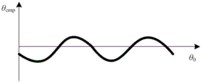
FIG. 4 is the linear interpolation table θ generated in step S15) in FIG. 2cmp=f(θ0);
FIG. 5 is a rotor position estimation angle θ obtained by detecting a PMSM by high frequency injection without second harmonic compensation0Actual angle theta with rotor position0Comparative figure of';
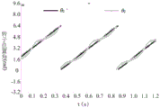
fig. 6 is a comparison diagram of an estimated rotor position angle θ and an actual rotor position angle θ' obtained by detecting a permanent magnet synchronous motor by a high-frequency injection method of second harmonic compensation according to an embodiment of the present invention after open loop compensation.
Detailed Description
The embodiment of the invention discloses a compensation method for detecting the position of a permanent magnet synchronous motor rotor by a high-frequency injection method, which comprises the following steps: s10), before detection, the linear interpolation table θ is determined in advancecmp=f(θ0) The linear interpolation table thetacmp=f(θ0) The characteristic is the inherent characteristic of the second harmonic of the permanent magnet synchronous motor; s20), during detection, according to the linear interpolation table thetacmp=f(θ0) To theta0Performing dynamic open loop compensation to eliminate the second harmonic generated during high frequency injection detection, wherein thetacmpCompensating the angle, theta, for rotor position0An angle is estimated for the rotor position.
The embodiment of the invention firstly discovers that the problem of generating the second harmonic wave generated by the factors such as the sub-salient pole effect and the parameter asymmetry of the permanent magnet synchronous motor belongs to the inherent characteristics of the body of the permanent magnet synchronous motor and basically keeps unchanged in the running process of the permanent magnet synchronous motor, and importantly, the embodiment of the invention predetermines the inherent characteristics of the second harmonic wave of the permanent magnet synchronous motor on the basis of the discovery, and then estimates the angle theta of the rotor position detected by a high-frequency injection method according to the predetermined inherent characteristics of the second harmonic wave when the rotor position of the permanent magnet synchronous motor is detected by the high-frequency injection method0The open-loop compensation is carried out in a simple and reliable manner, the problem of secondary harmonic wave existing in the permanent magnet synchronous motor can be obviously avoided or reduced, and the high-frequency injection method is not influencedDetecting rotor position estimation angle theta0The detection and estimation of the method can not bring new delay problems caused by a filter in the prior art, obviously and effectively improve the precision of detecting the position of the permanent magnet synchronous motor rotor by adopting a high-frequency injection method, and obviously improve the static and dynamic operation performance of the whole high-frequency injection method detection system.
In order to more clearly illustrate the embodiments of the present invention or the technical solutions in the prior art, the drawings used in the description of the embodiments or the prior art will be briefly described below, it is obvious that the drawings in the following description are only some embodiments described in the present invention, and for those skilled in the art, other drawings can be obtained according to the drawings without creative efforts.
Referring to fig. 1, a 500W/8-pole embedded permanent magnet synchronous motor platform adopts a compensation method for detecting the position of a rotor of an embedded permanent magnet synchronous motor by a high-frequency injection method, and comprises the following steps:
s10), before detection, the linear interpolation table θ is determined in advancecmp=f(θ0) The linear interpolation table thetacmp=f(θ0) The characteristic is the inherent characteristic of the second harmonic of the permanent magnet synchronous motor; preferably, in step S10), the linear interpolation table θ is determined by a self-calibration experimentcmp=f(θ0) (ii) a Preferably, referring further to fig. 2, the steps of the self-calibration experiment are as follows:
s11), the permanent magnet synchronous motor stably operates at a constant frequency, preferably, the constant frequency range is 1-10Hz, specifically, in the present embodiment, the constant frequency is 4 Hz;
s12), obtaining the rotor position estimation angle theta through high-frequency injection detection0Waveform diagram theta of0-t;
S13), estimating the angle θ from the rotor position0Is generated as an initial fit straight line thetaref0-t;
S14), please refer to fig. 3, estimate the angle θ based on the rotor position0Waveform diagram theta of0-t and the initial fitted straight line θref0T, will take the corresponding revolution at time tSub-position estimation angle theta0With the initial fitted linear value thetaref0Is used as a best-fit straight line target, and a best-fit straight line theta is determined by searching in a search arrow manner as shown in fig. 3ref-t;
S15), and obtaining the rotor position estimation angle theta corresponding to the t moment0And the best fit straight line value thetarefAs the rotor position compensation angle theta at the corresponding momentcmpTo generate a linear interpolation table thetacmp=f(θ0) Generating a linear interpolation table thetacmp=f(θ0) Please refer to fig. 4.
S20), when the permanent magnet synchronous motor is detected to normally run, the frequency of the permanent magnet synchronous motor is 2Hz, and the linear interpolation table theta is used for detecting the frequency of the permanent magnet synchronous motorcmp=f(θ0) To theta0Performing dynamic open loop compensation to eliminate the second harmonic generated during high frequency injection detection, wherein thetacmpCompensating the angle, theta, for rotor position0Estimating an angle for the rotor position; preferably, in this embodiment, the dynamic open loop compensation formula is: theta is equal to theta0-θcmpAnd theta is the rotor position estimation angle after open loop compensation.
Preferably, in this embodiment, the injection signal of the high-frequency injection method is a high-frequency pulsating voltage, and of course, in other embodiments of the present invention, the injection signal of the high-frequency injection method may also be a high-frequency pulsating current.
Preferably, in the present embodiment, the frequency range of the high-frequency pulse vibration voltage is 100-2000 Hz; specifically, in this embodiment, the frequency of the high-frequency pulsating voltage is 300Hz, and the high-frequency pulsating voltage is 15V.
It should be noted that, in the embodiment of the present invention, any one of the prior art may be adopted in the technical scheme of estimating the position angle of the rotor of the permanent magnet synchronous motor by using the high-frequency injection method; specifically, in the present embodiment, the calculation method for estimating the rotor position angle of the permanent magnet synchronous motor by the high-frequency injection method employs: in estimating rotor positionInjecting a high-frequency pulse vibration voltage signal with a certain amplitude at the position; next, detecting and estimating the amplitude of the high-frequency current component at the orthogonal axis of the rotor position angle, and taking the amplitude as the estimation error of the rotor position angle; finally, the rotor position angle is estimated by the PI regulator according to the estimation error of the rotor position angle, so as to obtain the rotor position estimation angle theta in the embodiment of the invention0(ii) a Obviously, in other embodiments of the present invention, a person skilled in the art may specifically implement the high-frequency injection method to estimate the rotor position angle of the permanent magnet synchronous motor by using other calculation method steps without creative efforts, and these embodiments may also achieve the significant technical effect in eliminating the second harmonic as in the above-mentioned embodiments of the present invention, and the present invention is not illustrated.
In order to verify the technical effect, the embodiment of the invention also provides a comparison embodiment for detecting the position of the rotor of the embedded permanent magnet synchronous motor by directly adopting a high-frequency injection method without carrying out secondary harmonic compensation, and the specific detection technical scheme is the same as that of the embodiment of the invention. After comparative implementation, the following results are found: compared with the technical scheme of the high-frequency injection method detection comparative example which does not adopt the second harmonic compensation, the technical scheme of the high-frequency injection method detection embodiment adopting the second harmonic compensation has the obvious technical effects that:
please refer to the rotor position estimation angle θ obtained by detecting the permanent magnet synchronous motor by the high frequency injection method without the second harmonic compensation obtained in the comparative example shown in fig. 50Actual angle theta with rotor position0' comparison of the values, as can be seen from FIG. 5, the rotor position estimation angle θ0Having a significant second harmonic component which is substantially at an actual angle theta to the rotor position0' maximum error of up to about 20 °; referring to fig. 6, a comparison graph of the rotor position estimated angle θ obtained after the open loop compensation and the rotor position actual angle θ 'obtained after the permanent magnet synchronous motor is detected by the high frequency injection method of the second harmonic compensation according to the embodiment of the present invention is shown, it can be seen from fig. 6 that the second harmonic of the rotor position estimated angle θ obtained after the open loop compensation is greatly reduced after the second harmonic compensation according to the present invention, and the error between the second harmonic and the rotor position actual angle θ' is controlled within 3 °, so that the present invention can be seen that the present invention has the advantages thatThe implementation scheme can obviously reduce the problem of second harmonic in the high-frequency injection method, effectively improves the precision of detecting the position of the rotor of the permanent magnet synchronous motor by adopting the high-frequency injection method, and obviously improves the static and dynamic operation performance of the whole high-frequency injection method detection system; the open loop compensation method of the embodiment of the invention is simple and reliable, and does not influence the high-frequency injection method to detect the rotor position estimation angle theta0And thus does not introduce new delay problems as the filters of the prior art.
Actual rotor position angle theta in comparative example of the present invention0'and the actual rotor position angle θ' in the embodiment of the present invention are detected by using a photoelectric encoder in the prior art.
It will be evident to those skilled in the art that the invention is not limited to the details of the foregoing illustrative embodiments, and that the present invention may be embodied in other specific forms without departing from the spirit or essential attributes thereof. The present embodiments are therefore to be considered in all respects as illustrative and not restrictive, the scope of the invention being indicated by the appended claims rather than by the foregoing description, and all changes which come within the meaning and range of equivalency of the claims are therefore intended to be embraced therein. Any reference sign in a claim should not be construed as limiting the claim concerned.
Furthermore, it should be understood that although the present description refers to embodiments, not every embodiment may contain only a single embodiment, and such description is for clarity only, and those skilled in the art should integrate the description, and the embodiments may be combined as appropriate to form other embodiments understood by those skilled in the art.
Claims (5)
1. A compensation method for detecting the position of a permanent magnet synchronous motor rotor by a high-frequency injection method is characterized by comprising the following steps:
s10), before detection, the linear interpolation table θ is determined in advancecmp=f(θ0) The linear interpolation table thetacmp=f(θ0) The characteristic is the inherent characteristic of the second harmonic of the permanent magnet synchronous motor;
s20), during detection, according to the linear interpolation table thetacmp=f(θ0) For the theta0Performing dynamic open loop compensation to eliminate second harmonic generated during high frequency injection detection, wherein theta iscmpCompensating the angle for rotor position, said theta0Estimating an angle for the rotor position;
in the step S10), the linear interpolation table theta is determined through self-calibration experimentscmp=f(θ0) (ii) a The steps of the self-calibration experiment are as follows:
s11), the permanent magnet synchronous motor stably runs at a constant frequency;
s12), obtaining the rotor position estimation angle theta through high-frequency injection detection0Waveform diagram theta of0-t;
S13), estimating the angle theta according to the rotor position0Is generated as an initial fit straight line thetaref0-t;
S14), estimating an angle θ based on the rotor position0Waveform diagram theta of0-t and the initial fitted straight line θref0T, the rotor position estimation angle θ corresponding to the time t will be taken0With the initial fitted linear value thetaref0The minimum difference value of the two-dimensional data is used as a best-fit straight line target, and a best-fit straight line theta is determined through searchingref-t;
S15), and obtaining the rotor position estimation angle theta corresponding to the t moment0And the best fit straight line value thetarefAs the rotor position compensation angle theta at the corresponding momentcmpTo generate a linear interpolation table thetacmp=f(θ0);
In step S20), the dynamic open loop compensation formula is: theta is equal to theta0-θcmpWherein, in the step (A),
and theta is the rotor position estimation angle after open loop compensation.
2. The compensation method for detecting the rotor position of the permanent magnet synchronous motor by the high-frequency injection method according to claim 1, wherein the injection signal of the high-frequency injection method is a high-frequency pulse vibration voltage.
3. The compensation method for detecting the rotor position of the permanent magnet synchronous motor by the high-frequency injection method according to claim 1, wherein the injection signal of the high-frequency injection method is a high-frequency pulse current.
4. The compensation method for detecting the rotor position of the PMSM according to claim 1, wherein the injection signal frequency range of the high frequency injection method is 100-2000 Hz.
5. The compensation method for detecting the rotor position of the permanent magnet synchronous motor by the high frequency injection method according to claim 1, wherein in the step S11), the constant frequency range is 1-10 Hz.
Priority Applications (1)
| Application Number | Priority Date | Filing Date | Title |
|---|---|---|---|
| CN201711195542.9A CN107911050B (en) | 2017-11-24 | 2017-11-24 | Compensation method for detecting position of permanent magnet synchronous motor rotor by high-frequency injection method |
Applications Claiming Priority (1)
| Application Number | Priority Date | Filing Date | Title |
|---|---|---|---|
| CN201711195542.9A CN107911050B (en) | 2017-11-24 | 2017-11-24 | Compensation method for detecting position of permanent magnet synchronous motor rotor by high-frequency injection method |
Publications (2)
| Publication Number | Publication Date |
|---|---|
| CN107911050A CN107911050A (en) | 2018-04-13 |
| CN107911050B true CN107911050B (en) | 2020-03-24 |
Family
ID=61848403
Family Applications (1)
| Application Number | Title | Priority Date | Filing Date |
|---|---|---|---|
| CN201711195542.9A Active CN107911050B (en) | 2017-11-24 | 2017-11-24 | Compensation method for detecting position of permanent magnet synchronous motor rotor by high-frequency injection method |
Country Status (1)
| Country | Link |
|---|---|
| CN (1) | CN107911050B (en) |
Families Citing this family (3)
| Publication number | Priority date | Publication date | Assignee | Title |
|---|---|---|---|---|
| CN113261178B (en) * | 2018-12-24 | 2024-10-01 | 鲲腾泰克(成都)科技有限公司 | Multiphase Motor/Generator Systems Using Harmonic Injection |
| CN109861611B (en) * | 2019-02-22 | 2021-04-06 | 中国第一汽车股份有限公司 | Error compensation system and method for position sensor of permanent magnet synchronous motor |
| CN117220549B (en) * | 2023-11-09 | 2024-01-26 | 徐州飞达电子科技有限公司 | A permanent magnet motor position detection method based on high-frequency injection |
Family Cites Families (6)
| Publication number | Priority date | Publication date | Assignee | Title |
|---|---|---|---|---|
| CN101505130B (en) * | 2009-03-17 | 2011-05-04 | 国电南端科技股份有限公司 | Rotor position estimation and correction method for permanent magnet synchronous generator |
| CN103840725B (en) * | 2012-11-26 | 2016-05-18 | 台达电子工业股份有限公司 | Device and method for measuring rotor position deviation of permanent magnet synchronous motor |
| CN104716884B (en) * | 2013-12-12 | 2017-10-31 | 西门子公司 | Device and method for the rotor-position of correcting motor |
| CN104660140A (en) * | 2015-01-16 | 2015-05-27 | 南京航空航天大学 | Permanent magnet synchronous motor initial position detection method based on high-frequency current signal injection |
| CN106655942B (en) * | 2017-03-01 | 2019-08-02 | 合肥工业大学 | Permanent magnet synchronous motor method for controlling position-less sensor |
| CN107241042B (en) * | 2017-06-12 | 2020-07-10 | 南京航空航天大学 | Signal extraction system and strategy of pulsed high-frequency signal injection method based on parallel EPLL |
-
2017
- 2017-11-24 CN CN201711195542.9A patent/CN107911050B/en active Active
Also Published As
| Publication number | Publication date |
|---|---|
| CN107911050A (en) | 2018-04-13 |
Similar Documents
| Publication | Publication Date | Title |
|---|---|---|
| CN105450127B (en) | Permanent magnet synchronous motor rotor position detection method based on high frequency electrocardiography | |
| CN102843091B (en) | A kind of determination methods of permanent-magnetic synchronous motor rotor initial position | |
| CN104158462B (en) | Method for detecting initial position of permanent magnet synchronous motor without position sensor | |
| CN109981001B (en) | A low noise permanent magnet synchronous motor rotor initial position detection method | |
| CN104660140A (en) | Permanent magnet synchronous motor initial position detection method based on high-frequency current signal injection | |
| CN109067283A (en) | A kind of permanent-magnetic synchronous motor rotor initial position identification system and method | |
| CN107911050B (en) | Compensation method for detecting position of permanent magnet synchronous motor rotor by high-frequency injection method | |
| CN105245151B (en) | The detection method of durface mounted permanent magnet synchronous motor rotor position | |
| CN103532465A (en) | Permanent magnet synchronous motor inductance identification algorithm based on incremental model reference adaptive system | |
| CN106655952A (en) | Current envelope curve method for detecting initial position of rotor of permanent magnet synchronous motor | |
| CN103701395B (en) | A kind of rotor initial position method of estimation based on positive and negative sequence harmonic injection | |
| CN104022710A (en) | Method of detecting initial position of surface-mounted permanent magnet synchronous motor rotor | |
| CN107947649B (en) | Motor rotor position correction method, device and equipment and storage medium | |
| CN103986394A (en) | Method for detecting initial position of surface mount type permanent magnet synchronous motor rotor | |
| CN110880897A (en) | Motor control method and device and driving device | |
| CN107872174B (en) | Compensation method for detecting position of permanent magnet synchronous motor rotor by high-frequency injection method | |
| CN112436762A (en) | Method for detecting initial position of rotor of permanent magnet synchronous motor | |
| CN113904604B (en) | Direct demodulation calculation method for three-stage synchronous motor rotor position estimation | |
| CN113691169B (en) | Motor rotor position detection method, device and motor controller | |
| CN112787559B (en) | Method for detecting initial position of permanent magnet motor rotor | |
| CN111817636A (en) | A Position Estimation Method for Permanent Magnet Synchronous Motors Based on High Frequency Sinusoidal Voltage Injection with Continuously Varying Frequency | |
| Ji et al. | Sensorless control for PMSM with novel back EMF observer based on quasi-PR controller | |
| CN110868112A (en) | Method and device for detecting initial position of motor rotor based on K-approach optimization estimation | |
| CN107769655B (en) | Method and device for estimating rotating speed of permanent magnet synchronous motor, computing equipment and storage medium | |
| CN118573063A (en) | Permanent magnet synchronous motor sensorless control method based on novel phase-locked loop |
Legal Events
| Date | Code | Title | Description |
|---|---|---|---|
| PB01 | Publication | ||
| PB01 | Publication | ||
| SE01 | Entry into force of request for substantive examination | ||
| SE01 | Entry into force of request for substantive examination | ||
| GR01 | Patent grant | ||
| GR01 | Patent grant |