CN1078752C - Cylindrical battery - Google Patents
Cylindrical battery Download PDFInfo
- Publication number
- CN1078752C CN1078752C CN96106236A CN96106236A CN1078752C CN 1078752 C CN1078752 C CN 1078752C CN 96106236 A CN96106236 A CN 96106236A CN 96106236 A CN96106236 A CN 96106236A CN 1078752 C CN1078752 C CN 1078752C
- Authority
- CN
- China
- Prior art keywords
- electrode
- substrate
- porosity layer
- interarea
- cylindrical battery
- Prior art date
- Legal status (The legal status is an assumption and is not a legal conclusion. Google has not performed a legal analysis and makes no representation as to the accuracy of the status listed.)
- Expired - Fee Related
Links
Images


Classifications
-
- H—ELECTRICITY
- H01—ELECTRIC ELEMENTS
- H01M—PROCESSES OR MEANS, e.g. BATTERIES, FOR THE DIRECT CONVERSION OF CHEMICAL ENERGY INTO ELECTRICAL ENERGY
- H01M4/00—Electrodes
- H01M4/02—Electrodes composed of, or comprising, active material
- H01M4/04—Processes of manufacture in general
- H01M4/0402—Methods of deposition of the material
- H01M4/0419—Methods of deposition of the material involving spraying
-
- H—ELECTRICITY
- H01—ELECTRIC ELEMENTS
- H01M—PROCESSES OR MEANS, e.g. BATTERIES, FOR THE DIRECT CONVERSION OF CHEMICAL ENERGY INTO ELECTRICAL ENERGY
- H01M10/00—Secondary cells; Manufacture thereof
- H01M10/24—Alkaline accumulators
- H01M10/28—Construction or manufacture
- H01M10/286—Cells or batteries with wound or folded electrodes
-
- H—ELECTRICITY
- H01—ELECTRIC ELEMENTS
- H01M—PROCESSES OR MEANS, e.g. BATTERIES, FOR THE DIRECT CONVERSION OF CHEMICAL ENERGY INTO ELECTRICAL ENERGY
- H01M10/00—Secondary cells; Manufacture thereof
- H01M10/34—Gastight accumulators
- H01M10/345—Gastight metal hydride accumulators
-
- H—ELECTRICITY
- H01—ELECTRIC ELEMENTS
- H01M—PROCESSES OR MEANS, e.g. BATTERIES, FOR THE DIRECT CONVERSION OF CHEMICAL ENERGY INTO ELECTRICAL ENERGY
- H01M4/00—Electrodes
- H01M4/02—Electrodes composed of, or comprising, active material
-
- H—ELECTRICITY
- H01—ELECTRIC ELEMENTS
- H01M—PROCESSES OR MEANS, e.g. BATTERIES, FOR THE DIRECT CONVERSION OF CHEMICAL ENERGY INTO ELECTRICAL ENERGY
- H01M4/00—Electrodes
- H01M4/02—Electrodes composed of, or comprising, active material
- H01M4/04—Processes of manufacture in general
-
- H—ELECTRICITY
- H01—ELECTRIC ELEMENTS
- H01M—PROCESSES OR MEANS, e.g. BATTERIES, FOR THE DIRECT CONVERSION OF CHEMICAL ENERGY INTO ELECTRICAL ENERGY
- H01M4/00—Electrodes
- H01M4/02—Electrodes composed of, or comprising, active material
- H01M4/04—Processes of manufacture in general
- H01M4/0402—Methods of deposition of the material
- H01M4/0404—Methods of deposition of the material by coating on electrode collectors
-
- H—ELECTRICITY
- H01—ELECTRIC ELEMENTS
- H01M—PROCESSES OR MEANS, e.g. BATTERIES, FOR THE DIRECT CONVERSION OF CHEMICAL ENERGY INTO ELECTRICAL ENERGY
- H01M4/00—Electrodes
- H01M4/02—Electrodes composed of, or comprising, active material
- H01M4/04—Processes of manufacture in general
- H01M4/043—Processes of manufacture in general involving compressing or compaction
-
- H—ELECTRICITY
- H01—ELECTRIC ELEMENTS
- H01M—PROCESSES OR MEANS, e.g. BATTERIES, FOR THE DIRECT CONVERSION OF CHEMICAL ENERGY INTO ELECTRICAL ENERGY
- H01M4/00—Electrodes
- H01M4/02—Electrodes composed of, or comprising, active material
- H01M4/24—Electrodes for alkaline accumulators
- H01M4/242—Hydrogen storage electrodes
-
- H—ELECTRICITY
- H01—ELECTRIC ELEMENTS
- H01M—PROCESSES OR MEANS, e.g. BATTERIES, FOR THE DIRECT CONVERSION OF CHEMICAL ENERGY INTO ELECTRICAL ENERGY
- H01M4/00—Electrodes
- H01M4/02—Electrodes composed of, or comprising, active material
- H01M4/24—Electrodes for alkaline accumulators
- H01M4/26—Processes of manufacture
-
- H—ELECTRICITY
- H01—ELECTRIC ELEMENTS
- H01M—PROCESSES OR MEANS, e.g. BATTERIES, FOR THE DIRECT CONVERSION OF CHEMICAL ENERGY INTO ELECTRICAL ENERGY
- H01M4/00—Electrodes
- H01M4/02—Electrodes composed of, or comprising, active material
- H01M4/64—Carriers or collectors
- H01M4/70—Carriers or collectors characterised by shape or form
- H01M4/80—Porous plates, e.g. sintered carriers
-
- H—ELECTRICITY
- H01—ELECTRIC ELEMENTS
- H01M—PROCESSES OR MEANS, e.g. BATTERIES, FOR THE DIRECT CONVERSION OF CHEMICAL ENERGY INTO ELECTRICAL ENERGY
- H01M6/00—Primary cells; Manufacture thereof
- H01M6/04—Cells with aqueous electrolyte
- H01M6/06—Dry cells, i.e. cells wherein the electrolyte is rendered non-fluid
- H01M6/10—Dry cells, i.e. cells wherein the electrolyte is rendered non-fluid with wound or folded electrodes
-
- H—ELECTRICITY
- H01—ELECTRIC ELEMENTS
- H01M—PROCESSES OR MEANS, e.g. BATTERIES, FOR THE DIRECT CONVERSION OF CHEMICAL ENERGY INTO ELECTRICAL ENERGY
- H01M4/00—Electrodes
- H01M4/02—Electrodes composed of, or comprising, active material
- H01M4/64—Carriers or collectors
- H01M4/70—Carriers or collectors characterised by shape or form
- H01M4/80—Porous plates, e.g. sintered carriers
- H01M4/808—Foamed, spongy materials
-
- Y—GENERAL TAGGING OF NEW TECHNOLOGICAL DEVELOPMENTS; GENERAL TAGGING OF CROSS-SECTIONAL TECHNOLOGIES SPANNING OVER SEVERAL SECTIONS OF THE IPC; TECHNICAL SUBJECTS COVERED BY FORMER USPC CROSS-REFERENCE ART COLLECTIONS [XRACs] AND DIGESTS
- Y02—TECHNOLOGIES OR APPLICATIONS FOR MITIGATION OR ADAPTATION AGAINST CLIMATE CHANGE
- Y02E—REDUCTION OF GREENHOUSE GAS [GHG] EMISSIONS, RELATED TO ENERGY GENERATION, TRANSMISSION OR DISTRIBUTION
- Y02E60/00—Enabling technologies; Technologies with a potential or indirect contribution to GHG emissions mitigation
- Y02E60/10—Energy storage using batteries
-
- Y—GENERAL TAGGING OF NEW TECHNOLOGICAL DEVELOPMENTS; GENERAL TAGGING OF CROSS-SECTIONAL TECHNOLOGIES SPANNING OVER SEVERAL SECTIONS OF THE IPC; TECHNICAL SUBJECTS COVERED BY FORMER USPC CROSS-REFERENCE ART COLLECTIONS [XRACs] AND DIGESTS
- Y02—TECHNOLOGIES OR APPLICATIONS FOR MITIGATION OR ADAPTATION AGAINST CLIMATE CHANGE
- Y02P—CLIMATE CHANGE MITIGATION TECHNOLOGIES IN THE PRODUCTION OR PROCESSING OF GOODS
- Y02P70/00—Climate change mitigation technologies in the production process for final industrial or consumer products
- Y02P70/50—Manufacturing or production processes characterised by the final manufactured product
Abstract
A cylindrical battery having a high utilization rate and a high discharge capacity rate is disclosed. It has an electrode group configured by rolling up two sheet electrodes of opposite polarity in spiral fashion interposing a separator therebetween, wherein one of the electrodes is provided with a porous metal substrate having a higher porosity layer and a lower porosity layer which has a considerably smaller thickness than that of the higher porosity layer, and an active material filled substantially in the spaces of the higher porosity layer of the porous metal substrate.
Description
The present invention relates to a kind of cylindrical battery, improvement with the battery lead plate that relates to alkaline battery with electrode assemblie of rolling by spiral form.
The electrode rough segmentation of battery is a three major types: paste type electrode, around junction electrode and bag type electrode.Recently, as a kind of new method of the nickel electrode of making alkaline battery, the method for making the paste type electrode has entered practical stage and frequent the use.This method comprises a pasty mixture of mainly being made up of active material powder (below, be referred to as " paste ") is filled into to have in the space three-dimensional communication space, that form in the porous substrate such as the non-woven fabric of foam metal or nickel fiber.
(being these spaces and the ratio in the shared zone of entire substrate) up to 95% because the porosity of this porous metals substrate, and the maximum gauge in these spaces is hundreds of μ m, thus might be in these spaces direct filling active material powder.Thereby available simple technology is processed into electrode with these metal substrate.
When these spaces that the high porosity that utilizes this substrate is inserted active material substrate were held the ground active material on the surface at substrate in other words and made the high capacity density electrode, a kind of like this porous metals substrate was of great use.Therefore but the active material conductivity is in general all very poor, will use additive such as cobalt compound to improve the utilance ratio of theoretical capacity (the actual discharge capacity with) and discharge capacity characteristics.
No matter above-mentioned traditional cobalt compound additive starts from the point of view of practical utility, still expectation can improve electrode, make it have higher capacity, moreover various additive also is among the research at present for the time being.
Main purpose of the present invention is to provide a kind of cylindrical battery of high power capacity by improving electrode, and this electrode has used the porous metals substrate with three-dimensional communication space.
Be provided with an electrode group by this battery of a kind of cylindrical battery that obtains of the present invention, this electrode group constitutes by roll two opposite polarity electrodes by spiral form, and inserts a spacer between two plate electrodes, and wherein at least one electrode comprises:
(a) a slice has the porous metals substrate in three-dimensional communication space, be used for when rolling the electrode group, comprising the active material that limits by first interarea and second interarea inwardly faced, substrate wherein have a higher porosity layer that is connected to first interarea and one be connected to second interarea than the low porosity layer, be significantly less than the thickness of higher porosity layer than the thickness of low porosity layer, and
(b) be filled in active material in the space of higher porosity layer.
The present invention also provides a kind of cylindrical battery with an electrode group, and this electrode group constitutes by rolling two opposite polarity electric structures by spiral form as mentioned above, and just second interarea of one of them electrode outwardly.
The present invention further also provides a kind of cylindrical battery that comprises an electrode group, this electrode group constitutes by rolling electrode, wherein on two interareas of an electrode, be provided with a plurality of groove or cutting wire casings that are parallel to the axis of the electrode group that son rolls, and second interarea wherein or outwardly inwardly.
In a preferred embodiment of the invention, an electrode be the nickel electrode that comprises the active material nickel hydroxide, another electrode is a negative electrode, this negative electrode comprise one such as the porous metals sheet the porous substrate and by a kind of active material mixture of this porous substrate supporting, this mixture mainly is made of hydrogen-bearing alloy powder.
In above-mentioned cylindrical battery, preferably without the face of one of active material coated electrode.
Though in appending claims, specifically proposed novel feature of the present invention, from detailed description, will be better understood and know from experience of the present invention in conjunction with arrangement and particular content and other purpose of the present invention and feature below in conjunction with accompanying drawing.
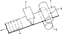
Fig. 1 is the method for electrode is made in expression by the present invention a perspective illustration;
Fig. 2 is the schematic diagram that the method for traditional electrode example is made in expression;
Fig. 3 is the perspective view that expression is cut open from the part of the state of cylindrical battery example extraction electrode of the present invention;
Fig. 4 is the profile of expression by the electrode group of rolling by spiral form of an example of the present invention;
Fig. 5 is the profile of expression by the electrode group of rolling by spiral form of another example of the present invention;
Fig. 6 is the another kind of method of electrode is made in expression by the present invention a perspective illustration;
Fig. 7 is the profile by the spiral-shaped electrode group rolled of expression by another enforcement of the present invention;
Fig. 8 is another method of electrode is made in expression by the present invention a perspective illustration;
Fig. 9 is the profile of expression by the battery pack of rolling by spiral form of another example of the present invention.
As discussed previously, the present invention relates to a kind of cylindrical battery, one of them electrode comprises a porous metals substrate, this substrate has a higher porosity layer and one than the low porosity layer, thickness than the Thickness Ratio higher porosity layer of low porosity layer is much smaller, and all is filled on the active material based base in the space of higher porosity layer of porous metals substrate.
In above-mentioned electrode, preferably basically do not fill active material than the low porosity layer, particularly do not cover with active material with the second interarea that links to each other than the low porosity layer. For for the low porosity layer, therefore the ratio that metal occupies in layer has larger electrical conductivity than the low porosity layer greater than this ratio in the higher porosity layer. Owing to effectively improved the electrical conductivity of electrode than the existence of low porosity layer, so improved utilization rate and the discharge capacity of battery.
In addition, when by rolling that electrode slice consists of the electrode group rolled by spiralization so that the low porosity layer of electrode inwardly (namely, center towards the electrode group) time, can make an electrode very little with distance between another electrode (periphery of its ragged edge contacts with battery case). Thereby utilization rate and the discharge capacity ratio of active principle have been improved.
When filling on the higher porosity layer of active material (namely when rolling electrode, be tending towards outside a side on) perpendicular to curl direction (axis direction that is parallel to the electrode group of having rolled) when a plurality of groove is provided, the bending of electrode slice is easy to, thereby electrode is rolled by spiral form be easy to. As a result, the zone of electrode reaction is obviously strengthened, thereby improved utilization rate and discharge capacity ratio.
On the contrary, if by rolling that electrode slice consists of the electrode group rolled by spiral form so that the low porosity layer of an electrode outwardly, in other words, the low porosity layer is towards the periphery of electrode group, then also the electrical conductivity of electrode be can improve because of the existence than the low porosity layer, and utilization rate and discharge capacity ratio improved.
When rolling low porosity layer that an electrode makes it outwardly or perpendicular to curl direction a plurality of groove is set inwardly and on than this side of low porosity layer, to make electrode slice crooked easily, and be easy to roll the electrode group by cylindrical shape, the section of electrode group is similar to real circle. As a result, the efficient of electrode reaction has improved, and has improved active utilization rate and discharge capacity ratio.
Below, with reference to preferred embodiment the present invention is described particularly.
Example 1
Prepare paste by the following stated: 10 parts of (by weight) particle diameters are about in the nickel hydroxide of the nickel metal powder of 2-3 μ m and cobalt oxide powder that 5 parts of (by weight) particle diameters the are about 2-3 μ m pulverulence that to be added to 100 parts of (by weight) average particulate diameters be 10 μ m, to be added to as the water of dispersive medium in the mixture of gained then, making the ratio of water in whole paste is 20% by weight, and then stirs the mixture that added water.
Fig. 1 schematically expresses a kind of method of making electrode by the present invention, in Fig. 1, a nozzle 3 is set, make it face a face of strip foaming nickel porous substrate 1, the width of this substrate 1 is that 100mm, thickness are that 2.5mm, porosity are 98%, average pore size is 200 μ m, and this is corresponding to the size in the three-dimensional communication space of this substrate.And, make the paste of making by the above mode insert the three-dimensional communication space of nickel porous substrate 1 by nozzle 3 ejections, also to carry the nickel porous substrate simultaneously along the longitudinal direction of substrate.In Fig. 1, the roller of nickel porous substrate is carried in label 5 and 6 representatives.
At filling process, keep the tip of nozzle 3 and the distance between the porous metals substrate 1 is 0.1mm, and will tie up the quantity of skill by the paste of nozzle 3 ejections, is the speed of 30-33 Grams Per Second.When filling paste in the space of nickel porous substrate, the transporting velocity that regulate the nickel porous substrate makes paste penetrate these spaces from a face of porous metals substrate but must not arrive at another face of porous metals substrate 1.Specifically, regulate filling process according to the transporting velocity at the bottom of the nickel porous village and make gap that paste can pass at most corresponding to about 80% of porous metals substrate thickness, but must not arrive at the porous metals substrate thickness all the other 20%.Found that preferred porous metals substrate transfer speed is 7 meters/minute.
Though in Fig. 1, done omission for the sake of brevity, but on another face of porous metals substrate 1, still to provide support the belt of porous metals substrate and roller, so that keep the folder end and the distance between the porous metals substrate 1 of nozzle 3 constant, though on the porous metals substrate because the effect of the paste of ejection also can keep this distance constant when having added a pressure.
Then, to having filled the porous metals substrate pressurization of paste, make its thickness be reduced to 1.0mm.By pressure process, make paste fill up the three-dimensional communication space of porous metals substrates basically fully.Not in the face of on the side of nozzle, these spaces flattenings of porous metals substrate are diminished, and reduced the porosity of porous metals substrates.As a result, increased metal structure shared ratio in substrate.Paste can not be protruded from the surface of this side, paste itself can not be exposed from this surface.
Then the above-mentioned porous metals substrate 1 of having filled paste is cut into the wide 35mm shown in the some tangent line among Fig. 1, the rectangular pieces of long 87mm.At a precalculated position point of the rectangular pieces 4 of the cutting leading-in conductor of burn-oning, thereby produce an electrode slice " a ".The quantitative range of effective material of filling in electrode slice " a " is the 9-10 gram.
Roll electrode " a ", the spacer of a known polypropylene non-woven fabric and the metal hydride negative electrode of a known hydrogen bearing alloy (comprising cerium alloy and nickel) that produces in a manner described as positive electrode by spiral form, spacer wherein is inserted between positive and negative two electrodes, thereby assembles out an electrode group.When assembling electrode group, roll two electrodes and spacer, make electrode " a " do not fill active material that face in, and a part of negative electrode will occupy the periphery on outermost limit.Then the electrode group that assembles is inserted in the columniform battery case.The alkaline electrolyte of predetermined quantity (2 milliliters) is injected the shell that surrounds the electrode group, and the openend of sealed disc can, thereby the specification of preparing as shown in Figure 3 is the columniform Ni-metal hydride accumulator A of 4/5A.
Fig. 3 expresses the state of battery A, has wherein cut away the part of battery case 10, and in order to describe electrode slice 7,9 and spacer 8 has been taken out from shell 10.Fig. 4 is the view of an amplification in the cross section of expression electrode group.
In these figure,, the disk 15 of an insulation is arranged at the inner bottom part of shell 10 being assembled in the battery case of making by nickel-clad steel plate 10 by the electrode of rolling positive electrode 7, spacer 8 and negative electrode 9 formations by spiral form.Though for avoiding the figure complexity to omit in the drawings, but the leading-in conductor of negative electrode 9 will be spoted weld on the shell 10.Flatten the surrounding edge of joint filling shell aperture end with sealed disc 11 and dead ring 12 by airtight and the close mode of liquid, thus the openend of can.A safety valve is set, this safety valve action when cell internal pressure surpasses a predetermined value on sealed disc 11.This safety valve is made of the lid 14 that is located at a steam vent (not shown) on the sealed disc 11, the rubber valve member 13 that seals this steam vent and this rubber valve member 13 of clamping.The leading-in conductor point of positive electrode 7 is welded on the sealing disk 11.
In this electrode group, positive electrode 7 is inwardly with that side that links to each other than low porosity layer 7a porous metals substrate 1, and in other words, low crack rate layer is towards the center of electrode group.
In order to compare, constitute a kind of battery B, wherein follow above-described step substantially, only be to use the nickel electrode " b " that produces by traditional paste injection method, wherein used two nozzles 3,3 of the both sides that are located at the porous substrate in moving as shown in Figure 2 to come to fill active material, and substrate has been cut into the back of identical size with electrode " a " in precalculated position point wire-lead of burn-oning to nickel foam porous substrate 1.
Also to constitute a kind of battery C, wherein follow the step identical substantially with battery A, just the curling mode of electrode group is different, positive electrode 7 and that side that links to each other than low porosity layer 7a porous metals substrate 1 are outwardly, in other words, than the outer periphery of low porosity layer, as shown in Figure 5 towards the electrode group.
Investigate the mean value of utilance of battery A, the B, the C that respectively are 100 by measuring the discharge capacity of battery when 0.2 coulomb of discharge.Also to measure they in the discharge capacity under 1 coulomb of discharging condition so that investigate the mean value of discharge capacity than (that is the ratio of the discharge capacity under the discharge capacity under 1 coulomb of discharging condition and 0.2 coulomb of discharging condition).Measurement result always is inserted in the following table 1.
Table 1
| The positive electrode utilance | The discharge capacity ratio | |
| Battery A | 98.5% | 94.0% |
| Battery B | 93.5% | 91.0% |
| Battery C | 99.9% | 95.5% |
High-visible as table 1, B compares with the reference examples battery, and recognizing by battery A of the present invention and C has excellent positive electrode utilance and discharge capacity ratio.
With regard to battery A, when rolling positive electrode 7, to arrange positive electrode 7 by spiral form, make do not fill active material than low porosity layer 7a inwardly.Therefore, an opposite side (having filled effective material) of positive electrode 7 is in the face of negative electrode 9, and the part of negative electrode 9 is located on the periphery on outermost limit of this electrode group and with battery case and contacts.Positive electrode 7 is improved with the reactivity of relative negative electrode 9, and and then has increased conductivity by the porous metals substrate than low porosity layer 7a.As a result, B compares with battery, has improved utilance and the discharge capacity ratio of battery A, and the positive electrode of battery B is that the connectivity gap on two faces is filled active material.
In battery C, (wherein roll electrode by spiral form outwardly than low porosity layer 7a), by means of the conductivity of also having improved electrode by the conducting surface that produces than low porosity layer 7a by what make the porous metals substrate.As a result, B compares with battery, and utilance and discharge capacity are than all having improved.
Example 2
Abide by substantially and make nickel electrode with example 1 identical paste prescription with example 1 similar step and employing.By at the roller 6a that is located at the band fin on the face of substrate (upside) and be located at carry the village between the return idler 5 on another face of substrate (downside) at the bottom of, and with two rollers from both sides extrusions substrate 1, thereby produce a plurality of grooves 2 at the face (upside) of strip foaming nickel porous substrate along the length direction of substrate.Then according to making paste can spray to a face (upside) of porous metals substrate 1, thereby make paste insert these spaces of substrate 1 by nozzle 3 with example 1 identical mode.Except above-mentioned additional step as shown in Figure 6, the mode that produces electrode is identical with example 1.This electrode is referred to as electrode " d " by the present invention.
Roll electrode " d ", the spacer of a non-programming fabric of known polypropylene and the metal hydride negative electrode of a known hydrogen bearing alloy (comprising cerium alloy and nickel) of the purposes positive electrode that produces in a manner described by spiral form, spacer wherein is inserted between positive and negative two electrodes, and " d " arranges to positive electrode, make have groove 2 a side outwardly, as shown in Figure 7, thus assemble out an electrode group.Then, with this electrode group by constituting a cylindrical battery (battery D) with example 1 similar mode.
In order to compare, also used above-mentioned battery B in this embodiment.Measuring respectively is 100 battery B and positive electrode utilance and the discharge capacity ratio of battery D.In following table 2, summed up the result of these measurements.
Table 2
| The positive electrode utilance | The discharge capacity ratio | |
| Battery B | 93.5% | 91.0% |
| Battery D | 96.5% | 93.0% |
High-visible as table 2, B compares with the reference examples battery, has improved utilance and discharge capacity ratio by battery D of the present invention.
The improvement in performance of battery D is owing to the structure of its electrode group, promptly when rolling positive electrode, negative electrode and spacer, make not by spiral form fill active positive electrode the side inwardly, and, make groove 2 towards outer periphery along being provided with groove 2 perpendicular to the electrode curl direction.By means of having increased porous metals substrate conductivity and having increased the inner surface of the real area of electrode reaction, the conductivity of the positive electrode of this structure is improved.
Example 3
Abide by substantially and make another nickel electrode with example 1 identical paste prescription with example 1 similar step and employing.By being located at the roller 5a that has fin on the face of substrate (downside) and being located at transport substrates between the return idler 6 on another face (upside) of substrate, and with two rollers from both sides at the bottom of squeezing the village 1, thereby produce a plurality of grooves 2 at the length direction of a face (downside) upper edge of strip foaming nickel porous substrate substrate.According to the mode identical, paste can be sprayed on the face (upside) of porous substrate 1 by nozzle 3, thereby make paste insert these spaces of substrate 1 then with example 1.Except above-mentioned additional step as shown in Figure 8, the mode that produces electrode is all identical with example 1.This electrode is referred to as electrode " e " by the present invention.
Roll in a manner described the metal hydride negative electrode of the electrode " e " that produces, known spacer and a known hydrogen bearing alloy (comprising cerium alloy and nickel) as positive electrode by spiral form, spacer wherein is inserted between positive and negative two electrodes, and positive electrode " e " arranged, make have groove 2 a side outwardly, as shown in Figure 9, thus assemble out an electrode group.Then, according to example 1 similar mode, constitute cylindrical battery (battery E) with this electrode group.For the battery E and the reference examples battery B that respectively are 100, measure the utilance and the discharge capacity ratio of positive electrode.In following table 3, summed up the result of these measurements.
Table 3
| The positive electrode utilance | The discharge capacity ratio | |
| Battery B | 93.5% | 91.0% |
| Battery E | 97.0% | 93.5% |
High-visible as table 3, B compares with the reference examples battery, has improved utilance and discharge capacity ratio by battery E of the present invention.
The improvement of battery E performance is owing to the structure of its electrode group, the not filling active material side that makes positive electrode when promptly rolling positive electrode, negative electrode and spacer by spiral form outwardly, and along being provided with groove 2 perpendicular to the electrode curl direction.In the electrode group that assembles, owing to produced the crack regularly along groove 2, so the cross section of cylindrical electrode group might become the real circle of expectation.By means of the conductivity that has increased the porous metals substrates and increased this outer surface with the efficient of negative reaction, the conductivity of the positive electrode of this structure is improved.
In above example, describe to be only limited to and use foamed nickel as the porous metals substrate.It goes without saying that,,, also can obtain and similar some technical advantages of foam-like nickel this moment as long as this, substrate had the three-dimensional communication space if adopt the non-woven fabric of the nickel fiber do not have frame structure and the sintered sheets of nickel by powder to prepare electrode.
As discussed previously, if use, just may provide cylindrical cell with high usage and high discharge capacity ratio by electrode of the present invention.
Though described the present invention with the foregoing description at present, not it should be understood that and should be construed to such disclosing restrictive.Concerning those skilled in the art, after having read above-mentioned disclosure, can make various replacements and improvement very easily undoubtedly.Therefore our expectation, appending claims should be interpreted into and cover all replacement and improvement that fall in design of the present invention and the scope.
Claims (10)
1. cylindrical battery that is provided with an electrode group, this electrode group constitutes by rolling two opposite polarity electrodes by spiral form and inserting a spacer betwixt, and wherein at least one described electrode comprises:
(a) a slice has the porous metals substrate in three-dimensional communication space, be used to comprise when rolling the active material that second interarea inwardly limits by first interarea and electrode group, wherein said substrate have the higher porosity layer that is connected to described first interarea and be connected to described second interarea than the low porosity layer, more much smaller than the thickness of low porosity layer than the thickness of higher porosity layer; And
(b) be filled in active material in described these spaces of described higher porosity layer.
2. cylindrical battery that is provided with an electrode group, this electrode group constitutes every the degree sheet by rolling two opposite polarity electrodes by spiral form and inserting one betwixt, and wherein at least one described electrode comprises:
(a) a slice has the porous metals substrate in three-dimensional communication space, be used to comprise when rolling effective material that second interarea outwardly limits by first interarea and electrode group, wherein said substrate have the higher porosity layer that is connected to described first interarea and be connected to described second interarea than the low porosity layer, more much smaller than the thickness of low porosity layer than the thickness of higher porosity layer; And
(b) be filled in the active material in described these spaces of described higher porosity layer.
3. cylindrical battery as claimed in claim 1 is characterized in that, is provided with a plurality of groove or cutting wire casings that are parallel to the axis that curls on described second interarea of a described electrode.
4. cylindrical battery as claimed in claim 2 is characterized in that, is provided with a plurality of groove or cutting wire casings that are parallel to the axis that curls on described second interarea of a described electrode.
5. cylindrical battery as claimed in claim 1 is characterized in that, is provided with a plurality of groove or cutting wire casings that are parallel to the axis that curls on described first interarea of a described electrode.
6. cylindrical battery as claimed in claim 2 is characterized in that, is provided with a plurality of groove or cutting wire casings that are parallel to the axis that curls on described first interarea of a described electrode.
7. cylindrical battery as claimed in claim 1 is characterized in that, the porous metals substrate of a described electrode is a foam-like nickel, and described active material is a nickel hydroxide.
8. cylindrical battery as claimed in claim 2 is characterized in that, the porous metals substrate of a described electrode is a foam-like nickel, and described active material is a nickel hydroxide.
9. cylindrical battery as claimed in claim 7 is characterized in that, wherein another electrode comprises a porous substrate and by the hydrogen-bearing alloy powder of described porous substrate supporting.
10. cylindrical battery as claimed in claim 8 is characterized in that, wherein another electrode comprises a porous substrate and by the hydrogen-bearing alloy powder of described porous substrate supporting.
Applications Claiming Priority (4)
| Application Number | Priority Date | Filing Date | Title |
|---|---|---|---|
| JP11044295 | 1995-05-09 | ||
| JP110442/95 | 1995-05-09 | ||
| JP7263758A JP2973894B2 (en) | 1995-05-09 | 1995-10-12 | Cylindrical battery |
| JP263758/95 | 1995-10-12 |
Publications (2)
| Publication Number | Publication Date |
|---|---|
| CN1138218A CN1138218A (en) | 1996-12-18 |
| CN1078752C true CN1078752C (en) | 2002-01-30 |
Family
ID=26450071
Family Applications (1)
| Application Number | Title | Priority Date | Filing Date |
|---|---|---|---|
| CN96106236A Expired - Fee Related CN1078752C (en) | 1995-05-09 | 1996-05-09 | Cylindrical battery |
Country Status (5)
| Country | Link |
|---|---|
| US (1) | US5637416A (en) |
| EP (1) | EP0742601B1 (en) |
| JP (1) | JP2973894B2 (en) |
| CN (1) | CN1078752C (en) |
| DE (1) | DE69608849T2 (en) |
Families Citing this family (24)
| Publication number | Priority date | Publication date | Assignee | Title |
|---|---|---|---|---|
| US5849430A (en) * | 1995-05-31 | 1998-12-15 | Samsung Display Devices Co., Ltd. | Structure of an electrode of a secondary battery |
| US5981108A (en) * | 1995-10-09 | 1999-11-09 | Matsushita Electric Industrial Co, Ltd. | Electrodes for battery and method of fabricating the same |
| KR100189808B1 (en) * | 1996-06-10 | 1999-06-01 | 손욱 | Wound electrode plate |
| KR100210502B1 (en) * | 1996-06-19 | 1999-07-15 | 손욱 | Separator for spiral electrode |
| JP3412437B2 (en) * | 1997-02-10 | 2003-06-03 | 松下電器産業株式会社 | Alkaline storage battery |
| US6287719B1 (en) * | 1998-06-15 | 2001-09-11 | Eveready Battery Company, Inc. | Battery including a non-aqueous multi-cell spiral-wound electrode assembly |
| JP2000285956A (en) * | 1999-03-30 | 2000-10-13 | Sanyo Electric Co Ltd | Cylindrical alkaline battery |
| JP4292436B2 (en) * | 1999-05-26 | 2009-07-08 | 住友電気工業株式会社 | Metal porous body, method for producing the same and battery current collector using the same |
| JP2000357519A (en) * | 1999-06-15 | 2000-12-26 | Katayama Tokushu Kogyo Kk | Porous metal body, battery electrode plate made of the body, and battery having the electrode plate |
| KR100305350B1 (en) * | 1999-07-01 | 2001-11-01 | 이계안 | assembling machine for negative electrode plate of Ni-MH battery and assembling process therefor |
| US6800398B1 (en) | 1999-07-21 | 2004-10-05 | Matsushita Electric Industrial Co., Ltd. | Alkaline storage battery pole plate and production method for alkaline storage battery pole plate and alkaline storage battery |
| US6479188B1 (en) | 1999-10-13 | 2002-11-12 | The Gillette Company | Cathode tube and method of making the same |
| JP4772185B2 (en) * | 2000-12-12 | 2011-09-14 | パナソニック株式会社 | Positive electrode plate for alkaline storage battery, method for producing the same, and alkaline storage battery using the same |
| JP4179943B2 (en) * | 2003-08-04 | 2008-11-12 | 三洋電機株式会社 | Cylindrical alkaline storage battery |
| US7846574B2 (en) | 2004-08-27 | 2010-12-07 | Panosonic Corporation | Positive electrode plate for alkaline storage battery and method for producing the same |
| US10418647B2 (en) | 2015-04-15 | 2019-09-17 | Lockheed Martin Energy, Llc | Mitigation of parasitic reactions within flow batteries |
| KR20180042852A (en) | 2015-08-19 | 2018-04-26 | 록히드 마틴 에너지, 엘엘씨 | Method of reducing solids in a flow battery |
| US10381674B2 (en) | 2016-04-07 | 2019-08-13 | Lockheed Martin Energy, Llc | High-throughput manufacturing processes for making electrochemical unit cells and electrochemical unit cells produced using the same |
| US10147957B2 (en) | 2016-04-07 | 2018-12-04 | Lockheed Martin Energy, Llc | Electrochemical cells having designed flow fields and methods for producing the same |
| US10109879B2 (en) | 2016-05-27 | 2018-10-23 | Lockheed Martin Energy, Llc | Flow batteries having an electrode with a density gradient and methods for production and use thereof |
| US10403911B2 (en) | 2016-10-07 | 2019-09-03 | Lockheed Martin Energy, Llc | Flow batteries having an interfacially bonded bipolar plate-electrode assembly and methods for production and use thereof |
| US10573899B2 (en) | 2016-10-18 | 2020-02-25 | Lockheed Martin Energy, Llc | Flow batteries having an electrode with differing hydrophilicity on opposing faces and methods for production and use thereof |
| US10581104B2 (en) | 2017-03-24 | 2020-03-03 | Lockheed Martin Energy, Llc | Flow batteries having a pressure-balanced electrochemical cell stack and associated methods |
| CN109244371B (en) * | 2018-10-16 | 2024-02-27 | 深圳吉阳智能科技有限公司 | Battery pole piece thermal compounding equipment |
Citations (2)
| Publication number | Priority date | Publication date | Assignee | Title |
|---|---|---|---|---|
| JPS60133655A (en) * | 1983-12-21 | 1985-07-16 | Matsushita Electric Ind Co Ltd | Positive plate for cylindrical sealed type nickel-cadmium storage battery |
| JPS62139256A (en) * | 1985-12-11 | 1987-06-22 | Matsushita Electric Ind Co Ltd | Sealed nickel-cadmium storage battery |
Family Cites Families (11)
| Publication number | Priority date | Publication date | Assignee | Title |
|---|---|---|---|---|
| US3314821A (en) * | 1964-02-28 | 1967-04-18 | Sylvania Electric Prod | Storage battery electrode of sintered metal particles |
| FR2087324A5 (en) * | 1970-05-14 | 1971-12-31 | Wonder | |
| JPS55108182A (en) * | 1979-02-14 | 1980-08-19 | Furukawa Battery Co Ltd:The | Alkali storage battery |
| US4251603A (en) * | 1980-02-13 | 1981-02-17 | Matsushita Electric Industrial Co., Ltd. | Battery electrode |
| JPS58161251A (en) * | 1982-03-19 | 1983-09-24 | Japan Storage Battery Co Ltd | Manufacture of spiral positive plate for alkali cell |
| JPS59207560A (en) * | 1983-05-11 | 1984-11-24 | Matsushita Electric Ind Co Ltd | Manufacture of electrode for battery |
| JPH0752647B2 (en) * | 1986-09-26 | 1995-06-05 | 松下電器産業株式会社 | Battery electrode and method for manufacturing the same |
| JP2762782B2 (en) * | 1991-08-02 | 1998-06-04 | 松下電器産業株式会社 | Sealed battery |
| US5487961A (en) * | 1992-04-24 | 1996-01-30 | Eveready Battery Company, Inc. | Sintered metal electrode |
| EP0674810B1 (en) * | 1992-11-20 | 2001-05-16 | National-Standard Company | Battery electrode substrates and methods of making the same |
| JP2639620B2 (en) * | 1993-10-13 | 1997-08-13 | 古河電池株式会社 | Manufacturing method of hydrogen storage alloy electrode |
-
1995
- 1995-10-12 JP JP7263758A patent/JP2973894B2/en not_active Expired - Fee Related
-
1996
- 1996-03-19 US US08/618,644 patent/US5637416A/en not_active Expired - Fee Related
- 1996-04-18 EP EP96302727A patent/EP0742601B1/en not_active Expired - Lifetime
- 1996-04-18 DE DE69608849T patent/DE69608849T2/en not_active Expired - Fee Related
- 1996-05-09 CN CN96106236A patent/CN1078752C/en not_active Expired - Fee Related
Patent Citations (2)
| Publication number | Priority date | Publication date | Assignee | Title |
|---|---|---|---|---|
| JPS60133655A (en) * | 1983-12-21 | 1985-07-16 | Matsushita Electric Ind Co Ltd | Positive plate for cylindrical sealed type nickel-cadmium storage battery |
| JPS62139256A (en) * | 1985-12-11 | 1987-06-22 | Matsushita Electric Ind Co Ltd | Sealed nickel-cadmium storage battery |
Also Published As
| Publication number | Publication date |
|---|---|
| EP0742601A1 (en) | 1996-11-13 |
| JP2973894B2 (en) | 1999-11-08 |
| CN1138218A (en) | 1996-12-18 |
| DE69608849T2 (en) | 2001-02-01 |
| DE69608849D1 (en) | 2000-07-20 |
| EP0742601B1 (en) | 2000-06-14 |
| US5637416A (en) | 1997-06-10 |
| JPH0927342A (en) | 1997-01-28 |
Similar Documents
| Publication | Publication Date | Title |
|---|---|---|
| CN1078752C (en) | Cylindrical battery | |
| CN1244965C (en) | Non-sintered thin electrode for battery, battery using said electrode and its manufacture method | |
| US9793537B2 (en) | Three dimensional co-extruded battery electrodes | |
| CN1192445C (en) | Electrode and battery | |
| EP2559084B1 (en) | Battery, battery plate assembly, and method of assembly | |
| EP2273580A2 (en) | Bi-polar rechargeable electrochemical battery | |
| US20100304191A1 (en) | Energy storage devices having cells electrically coupled in series and in parallel | |
| CN1168164C (en) | Method of mfg. electrode of battery | |
| US11824204B2 (en) | Battery and battery plate assembly with absorbent separator | |
| CN1080463C (en) | Electrodes for battery and method for fabricating the same | |
| KR20020053807A (en) | Rechargeable nickel-zinc cells | |
| CN1426609A (en) | Cell tube and method of manufacturing cell tube | |
| JP4711250B2 (en) | Nickel electrode for secondary battery and its manufacturing method | |
| JP2002198055A (en) | Paste-like thin electrode for battery, its manufacturing method and secondary battery | |
| CN108767192A (en) | Based lithium-ion battery positive plate and lithium ion battery | |
| CN1217437C (en) | Electrode plate of alkaline storage battery, and alkaline storage battery using same | |
| CN1222061C (en) | Rectangle alkaline accumdulator | |
| CN113793972A (en) | Battery and preparation method thereof | |
| CN2469560Y (en) | Alkaline accumulator | |
| CN201142347Y (en) | High capacity nickel-hydrogen cell | |
| CN219832699U (en) | High-capacity battery pole piece structure | |
| JP3928039B2 (en) | Active material filling method of nickel electrode for secondary battery | |
| CN220065740U (en) | Sodium battery silicon-containing thick pole piece | |
| CN1409419A (en) | Alkaline accumulator and its producing method | |
| EP0742600A1 (en) | Electrodes for battery and method for fabricating the same |
Legal Events
| Date | Code | Title | Description |
|---|---|---|---|
| C10 | Entry into substantive examination | ||
| SE01 | Entry into force of request for substantive examination | ||
| C06 | Publication | ||
| PB01 | Publication | ||
| C14 | Grant of patent or utility model | ||
| GR01 | Patent grant | ||
| C19 | Lapse of patent right due to non-payment of the annual fee | ||
| CF01 | Termination of patent right due to non-payment of annual fee |