CN1078555C - Regenerating control device for bicycle with auxiliary power - Google Patents
Regenerating control device for bicycle with auxiliary power Download PDFInfo
- Publication number
- CN1078555C CN1078555C CN97103389A CN97103389A CN1078555C CN 1078555 C CN1078555 C CN 1078555C CN 97103389 A CN97103389 A CN 97103389A CN 97103389 A CN97103389 A CN 97103389A CN 1078555 C CN1078555 C CN 1078555C
- Authority
- CN
- China
- Prior art keywords
- power
- power recovery
- mentioned
- motor
- pedaling
- Prior art date
- Legal status (The legal status is an assumption and is not a legal conclusion. Google has not performed a legal analysis and makes no representation as to the accuracy of the status listed.)
- Expired - Fee Related
Links
Images


Classifications
-
- B—PERFORMING OPERATIONS; TRANSPORTING
- B62—LAND VEHICLES FOR TRAVELLING OTHERWISE THAN ON RAILS
- B62M—RIDER PROPULSION OF WHEELED VEHICLES OR SLEDGES; POWERED PROPULSION OF SLEDGES OR SINGLE-TRACK CYCLES; TRANSMISSIONS SPECIALLY ADAPTED FOR SUCH VEHICLES
- B62M6/00—Rider propulsion of wheeled vehicles with additional source of power, e.g. combustion engine or electric motor
- B62M6/40—Rider propelled cycles with auxiliary electric motor
- B62M6/45—Control or actuating devices therefor
-
- B—PERFORMING OPERATIONS; TRANSPORTING
- B60—VEHICLES IN GENERAL
- B60L—PROPULSION OF ELECTRICALLY-PROPELLED VEHICLES; SUPPLYING ELECTRIC POWER FOR AUXILIARY EQUIPMENT OF ELECTRICALLY-PROPELLED VEHICLES; ELECTRODYNAMIC BRAKE SYSTEMS FOR VEHICLES IN GENERAL; MAGNETIC SUSPENSION OR LEVITATION FOR VEHICLES; MONITORING OPERATING VARIABLES OF ELECTRICALLY-PROPELLED VEHICLES; ELECTRIC SAFETY DEVICES FOR ELECTRICALLY-PROPELLED VEHICLES
- B60L15/00—Methods, circuits, or devices for controlling the traction-motor speed of electrically-propelled vehicles
- B60L15/20—Methods, circuits, or devices for controlling the traction-motor speed of electrically-propelled vehicles for control of the vehicle or its driving motor to achieve a desired performance, e.g. speed, torque, programmed variation of speed
- B60L15/2009—Methods, circuits, or devices for controlling the traction-motor speed of electrically-propelled vehicles for control of the vehicle or its driving motor to achieve a desired performance, e.g. speed, torque, programmed variation of speed for braking
-
- B—PERFORMING OPERATIONS; TRANSPORTING
- B60—VEHICLES IN GENERAL
- B60L—PROPULSION OF ELECTRICALLY-PROPELLED VEHICLES; SUPPLYING ELECTRIC POWER FOR AUXILIARY EQUIPMENT OF ELECTRICALLY-PROPELLED VEHICLES; ELECTRODYNAMIC BRAKE SYSTEMS FOR VEHICLES IN GENERAL; MAGNETIC SUSPENSION OR LEVITATION FOR VEHICLES; MONITORING OPERATING VARIABLES OF ELECTRICALLY-PROPELLED VEHICLES; ELECTRIC SAFETY DEVICES FOR ELECTRICALLY-PROPELLED VEHICLES
- B60L50/00—Electric propulsion with power supplied within the vehicle
- B60L50/20—Electric propulsion with power supplied within the vehicle using propulsion power generated by humans or animals
-
- B—PERFORMING OPERATIONS; TRANSPORTING
- B60—VEHICLES IN GENERAL
- B60L—PROPULSION OF ELECTRICALLY-PROPELLED VEHICLES; SUPPLYING ELECTRIC POWER FOR AUXILIARY EQUIPMENT OF ELECTRICALLY-PROPELLED VEHICLES; ELECTRODYNAMIC BRAKE SYSTEMS FOR VEHICLES IN GENERAL; MAGNETIC SUSPENSION OR LEVITATION FOR VEHICLES; MONITORING OPERATING VARIABLES OF ELECTRICALLY-PROPELLED VEHICLES; ELECTRIC SAFETY DEVICES FOR ELECTRICALLY-PROPELLED VEHICLES
- B60L50/00—Electric propulsion with power supplied within the vehicle
- B60L50/50—Electric propulsion with power supplied within the vehicle using propulsion power supplied by batteries or fuel cells
- B60L50/52—Electric propulsion with power supplied within the vehicle using propulsion power supplied by batteries or fuel cells characterised by DC-motors
-
- B—PERFORMING OPERATIONS; TRANSPORTING
- B60—VEHICLES IN GENERAL
- B60L—PROPULSION OF ELECTRICALLY-PROPELLED VEHICLES; SUPPLYING ELECTRIC POWER FOR AUXILIARY EQUIPMENT OF ELECTRICALLY-PROPELLED VEHICLES; ELECTRODYNAMIC BRAKE SYSTEMS FOR VEHICLES IN GENERAL; MAGNETIC SUSPENSION OR LEVITATION FOR VEHICLES; MONITORING OPERATING VARIABLES OF ELECTRICALLY-PROPELLED VEHICLES; ELECTRIC SAFETY DEVICES FOR ELECTRICALLY-PROPELLED VEHICLES
- B60L50/00—Electric propulsion with power supplied within the vehicle
- B60L50/50—Electric propulsion with power supplied within the vehicle using propulsion power supplied by batteries or fuel cells
- B60L50/60—Electric propulsion with power supplied within the vehicle using propulsion power supplied by batteries or fuel cells using power supplied by batteries
- B60L50/66—Arrangements of batteries
-
- B—PERFORMING OPERATIONS; TRANSPORTING
- B60—VEHICLES IN GENERAL
- B60L—PROPULSION OF ELECTRICALLY-PROPELLED VEHICLES; SUPPLYING ELECTRIC POWER FOR AUXILIARY EQUIPMENT OF ELECTRICALLY-PROPELLED VEHICLES; ELECTRODYNAMIC BRAKE SYSTEMS FOR VEHICLES IN GENERAL; MAGNETIC SUSPENSION OR LEVITATION FOR VEHICLES; MONITORING OPERATING VARIABLES OF ELECTRICALLY-PROPELLED VEHICLES; ELECTRIC SAFETY DEVICES FOR ELECTRICALLY-PROPELLED VEHICLES
- B60L7/00—Electrodynamic brake systems for vehicles in general
- B60L7/10—Dynamic electric regenerative braking
- B60L7/12—Dynamic electric regenerative braking for vehicles propelled by dc motors
-
- B—PERFORMING OPERATIONS; TRANSPORTING
- B62—LAND VEHICLES FOR TRAVELLING OTHERWISE THAN ON RAILS
- B62M—RIDER PROPULSION OF WHEELED VEHICLES OR SLEDGES; POWERED PROPULSION OF SLEDGES OR SINGLE-TRACK CYCLES; TRANSMISSIONS SPECIALLY ADAPTED FOR SUCH VEHICLES
- B62M6/00—Rider propulsion of wheeled vehicles with additional source of power, e.g. combustion engine or electric motor
- B62M6/40—Rider propelled cycles with auxiliary electric motor
- B62M6/55—Rider propelled cycles with auxiliary electric motor power-driven at crank shafts parts
-
- B—PERFORMING OPERATIONS; TRANSPORTING
- B60—VEHICLES IN GENERAL
- B60L—PROPULSION OF ELECTRICALLY-PROPELLED VEHICLES; SUPPLYING ELECTRIC POWER FOR AUXILIARY EQUIPMENT OF ELECTRICALLY-PROPELLED VEHICLES; ELECTRODYNAMIC BRAKE SYSTEMS FOR VEHICLES IN GENERAL; MAGNETIC SUSPENSION OR LEVITATION FOR VEHICLES; MONITORING OPERATING VARIABLES OF ELECTRICALLY-PROPELLED VEHICLES; ELECTRIC SAFETY DEVICES FOR ELECTRICALLY-PROPELLED VEHICLES
- B60L2200/00—Type of vehicles
- B60L2200/12—Bikes
-
- B—PERFORMING OPERATIONS; TRANSPORTING
- B60—VEHICLES IN GENERAL
- B60L—PROPULSION OF ELECTRICALLY-PROPELLED VEHICLES; SUPPLYING ELECTRIC POWER FOR AUXILIARY EQUIPMENT OF ELECTRICALLY-PROPELLED VEHICLES; ELECTRODYNAMIC BRAKE SYSTEMS FOR VEHICLES IN GENERAL; MAGNETIC SUSPENSION OR LEVITATION FOR VEHICLES; MONITORING OPERATING VARIABLES OF ELECTRICALLY-PROPELLED VEHICLES; ELECTRIC SAFETY DEVICES FOR ELECTRICALLY-PROPELLED VEHICLES
- B60L2240/00—Control parameters of input or output; Target parameters
- B60L2240/10—Vehicle control parameters
- B60L2240/12—Speed
-
- B—PERFORMING OPERATIONS; TRANSPORTING
- B60—VEHICLES IN GENERAL
- B60L—PROPULSION OF ELECTRICALLY-PROPELLED VEHICLES; SUPPLYING ELECTRIC POWER FOR AUXILIARY EQUIPMENT OF ELECTRICALLY-PROPELLED VEHICLES; ELECTRODYNAMIC BRAKE SYSTEMS FOR VEHICLES IN GENERAL; MAGNETIC SUSPENSION OR LEVITATION FOR VEHICLES; MONITORING OPERATING VARIABLES OF ELECTRICALLY-PROPELLED VEHICLES; ELECTRIC SAFETY DEVICES FOR ELECTRICALLY-PROPELLED VEHICLES
- B60L2240/00—Control parameters of input or output; Target parameters
- B60L2240/40—Drive Train control parameters
- B60L2240/42—Drive Train control parameters related to electric machines
- B60L2240/421—Speed
-
- B—PERFORMING OPERATIONS; TRANSPORTING
- B60—VEHICLES IN GENERAL
- B60L—PROPULSION OF ELECTRICALLY-PROPELLED VEHICLES; SUPPLYING ELECTRIC POWER FOR AUXILIARY EQUIPMENT OF ELECTRICALLY-PROPELLED VEHICLES; ELECTRODYNAMIC BRAKE SYSTEMS FOR VEHICLES IN GENERAL; MAGNETIC SUSPENSION OR LEVITATION FOR VEHICLES; MONITORING OPERATING VARIABLES OF ELECTRICALLY-PROPELLED VEHICLES; ELECTRIC SAFETY DEVICES FOR ELECTRICALLY-PROPELLED VEHICLES
- B60L2240/00—Control parameters of input or output; Target parameters
- B60L2240/40—Drive Train control parameters
- B60L2240/42—Drive Train control parameters related to electric machines
- B60L2240/423—Torque
-
- Y—GENERAL TAGGING OF NEW TECHNOLOGICAL DEVELOPMENTS; GENERAL TAGGING OF CROSS-SECTIONAL TECHNOLOGIES SPANNING OVER SEVERAL SECTIONS OF THE IPC; TECHNICAL SUBJECTS COVERED BY FORMER USPC CROSS-REFERENCE ART COLLECTIONS [XRACs] AND DIGESTS
- Y02—TECHNOLOGIES OR APPLICATIONS FOR MITIGATION OR ADAPTATION AGAINST CLIMATE CHANGE
- Y02T—CLIMATE CHANGE MITIGATION TECHNOLOGIES RELATED TO TRANSPORTATION
- Y02T10/00—Road transport of goods or passengers
- Y02T10/60—Other road transportation technologies with climate change mitigation effect
- Y02T10/64—Electric machine technologies in electromobility
-
- Y—GENERAL TAGGING OF NEW TECHNOLOGICAL DEVELOPMENTS; GENERAL TAGGING OF CROSS-SECTIONAL TECHNOLOGIES SPANNING OVER SEVERAL SECTIONS OF THE IPC; TECHNICAL SUBJECTS COVERED BY FORMER USPC CROSS-REFERENCE ART COLLECTIONS [XRACs] AND DIGESTS
- Y02—TECHNOLOGIES OR APPLICATIONS FOR MITIGATION OR ADAPTATION AGAINST CLIMATE CHANGE
- Y02T—CLIMATE CHANGE MITIGATION TECHNOLOGIES RELATED TO TRANSPORTATION
- Y02T10/00—Road transport of goods or passengers
- Y02T10/60—Other road transportation technologies with climate change mitigation effect
- Y02T10/70—Energy storage systems for electromobility, e.g. batteries
-
- Y—GENERAL TAGGING OF NEW TECHNOLOGICAL DEVELOPMENTS; GENERAL TAGGING OF CROSS-SECTIONAL TECHNOLOGIES SPANNING OVER SEVERAL SECTIONS OF THE IPC; TECHNICAL SUBJECTS COVERED BY FORMER USPC CROSS-REFERENCE ART COLLECTIONS [XRACs] AND DIGESTS
- Y02—TECHNOLOGIES OR APPLICATIONS FOR MITIGATION OR ADAPTATION AGAINST CLIMATE CHANGE
- Y02T—CLIMATE CHANGE MITIGATION TECHNOLOGIES RELATED TO TRANSPORTATION
- Y02T10/00—Road transport of goods or passengers
- Y02T10/60—Other road transportation technologies with climate change mitigation effect
- Y02T10/72—Electric energy management in electromobility
Abstract
The present invention is to provide a regeneration control device for a bicycle with an auxiliary motor which can control a motor in a state of regeneration to charge a battery and to keep comfortable running when pressing force is too small for a bicycle speed. In a bicycle with an auxiliary motor having a drive control means for drive-controlling a motor so as to generate assisting force corresponding to pressing force on a pedal, the bicycle with an auxiliary motor is provided with a bicycle speed detection means for detecting the speed of the bicycle, a pressing force detection means for detecting pressing force on the pedal, and a regeneration control device which judges the necessity of regeneration based on a bicycle speed detected by the bicycle speed detection means and pressing force detected by the pressing force detection means and then changes the motor to a state of regeneration.
Description
The present invention relates to the bicycle with auxiliary power, it is with the power of power-assisted cyclist's Pedalling of motor.
So far, propose, wherein mention the scheme that produces the control of braking of braking force by motor, open disclosed example flat 4-100790 number as the Japanese patent gazette spy about the existing all schemes of the bicycle of band auxiliary power.
In this example, putting down in writing: " under situations such as descending road surface, making it have a kind of Jake brake effect ", " detect the braking that has applied by braking sensor, produce braking force " by motor.
, produce braking force though this example records by motor, not mentioning the state that makes motor produce braking force is the occasion that motor is worked as electrical generator, and consequent power recovery is arrived battery.
But the control motor power reclaims to be considered easily.
In above-mentioned example, making motor produce braking force is when braking sensor detects brake activation, and therefore before brake activation, the braking force that does not exist motor to produce is so also just can not reclaim electric power.
Because glancing impact, Pedalling not normally, thereby motor does not produce braking force as electrical generator when Pedalling, is not in the power recovery state yet.
Having under the bicycle occasion of auxiliary power, because the power-assisted of motor manpower, thereby compare with common bicycle pedal pedal can be lightly, and still, the power of pedaling of comparing Pedalling with the speed of a motor vehicle becomes too little may being caused by the descending road surface.
The power of pedaling of comparing Pedalling with the speed of a motor vehicle is too little to hinder agreeable travelling on the contrary, and particularly, if be in acceleration mode, then speed increases gradually, and the result must brake speed is reduced, thereby the agreeable travelling that is hard to keep.
Under above-mentioned occasion with preceding example, owing to do not add braking during Pedalling, thus the braking force that produces by motor not, thereby when appearing at Pedalling, pedal the situation that power too diminishes with respect to speed, this can hinder agreeable travelling.
The present invention makes in order to overcome the problems referred to above, its objective is the power recovery control setup that a kind of bicycle with auxiliary power is provided, it is to compare with the speed of a motor vehicle under the too small occasion of the power of pedaling of pedal, motor is controlled to the power recovery state, battery is charged, and can keep agreeable travelling.
In order to achieve the above object, the bicycle power recovery control setup that has auxiliary drive of the present invention's first scheme, it is provided with the motor that produces the auxiliary force that adapts with the power of pedaling on the pedal that is applied to and this motor is carried out the driving control device of drive controlling, and it also is provided with: the vehicle speed detector device that detects the speed of a motor vehicle of this bicycle; Detection is applied to the force checking device of pedaling of the power of pedaling on the pedal; According to above-mentioned the vehicle speed detector device speed of a motor vehicle that detects and the power of pedaling of pedaling the force checking device detection, determine the power recovery decision content of the power of pedaling and the control circuit of being stored corresponding to the speed of a motor vehicle in advance, pedal detected actual the pedaling under the little occasion of the above-mentioned power recovery decision content of force rate of force checking device above-mentioned under a certain speed of a motor vehicle, convert said motor to the power recovery state.
Because the power recovery control setup is judged the essentiality that reclaims electric power according to the speed of a motor vehicle and the power of pedaling, thereby pedal power and become to be judged as when too small and need to reclaim electric power comparing pedal with the speed of a motor vehicle, and convert motor to the power recovery state, make motor become the power recovery state thus and as electrical generator, give battery the power recovery that takes place, can suppress the power consumption of battery, and can work the braking force as electrical generator of motor to this bicycle, thereby can keep agreeable travelling.
Set this power recovery decision content if cooperate agreeable motoring condition, then pedal power and be varied down to and be lower than the power recovery decision content when following when compare pedal with the speed of a motor vehicle, just can convert motor to the power recovery state, can charge battery, and approaching agreeable the travelling by the braking force effect.
The power recovery control setup of the bicycle of the band auxiliary power of alternative plan of the present invention, on the basis of above-mentioned first scheme, above-mentioned power recovery control setup be with under the drive controlling that forms by above-mentioned driving control device, corresponding to the speed of a motor vehicle obtain the needed power of pedaling of travelling on flat road surface in advance, it as the power recovery decision content and stored, pedal actual the pedaling under the little occasion of the above-mentioned power recovery decision content of force rate that force checking device detects above-mentioned under a certain speed of a motor vehicle, convert said motor to the power recovery state.
Because the power recovery control setup is under the drive controlling that is formed by above-mentioned driving control device, obtain the needed power of pedaling on flat road surface of travelling accordingly in advance with the speed of a motor vehicle, it is stored as the power recovery decision content, thereby, when the speed of a motor vehicle of actual detected is compared with the power recovery decision content of pedaling power and storage, if actual to pedal force rate power recovery decision content little, just can be judged to be essential power recovery, make motor become the power recovery state, battery is charged, and can regardless of the state in downhill path how on flat road surface, keep agreeable travelling with travel agreeablely the samely.
The power recovery control setup of the bicycle of the band auxiliary power of third party's case of the present invention, on the basis of above-mentioned alternative plan, the speed of a motor vehicle that above-mentioned power recovery control setup detects according to above-mentioned vehicle speed detector device changes the computing acceleration/accel, the pedaling under the little occasion of force rate power recovery decision content of above-mentioned reality, only above-mentioned acceleration/accel be on the occasion of the time, said motor is converted to the power recovery state.
Because acceleration/accel is zero or negative value, promptly is in when keeping certain speed or deceleration regime, even compare pedal pedals power and diminishes with the speed of a motor vehicle, before upsetting the certain speed state, power recovery need not be carried out, also the further aggravation of slowing down need not be made by power recovery, thereby under this occasion, do not make motor become the power recovery state.
The power recovery control setup of the bicycle of the band auxiliary power of the cubic case of the present invention, on the basis of above-mentioned third party's case, above-mentioned power recovery control setup is that to pedal the actual power of pedaling that force checking device detects be under zero the occasion above-mentioned, above-mentioned acceleration/accel be on the occasion of the time, said motor is converted to the power recovery state.
Because not during Pedalling, only otherwise, just need not make the motor power recovery and make it play brake action, thereby under this occasion, not make motor convert the power recovery state at acceleration mode.
Fig. 1 is the unitary side view of bicycle of the band auxiliary power of one embodiment of the invention,
Fig. 2 is the enlarged side view of main portion shown in Figure 1,
Fig. 3 is the cross sectional drawing that the III-III line along Fig. 2 blocks,
Fig. 4 is the control system schematic block diagram as the Direct Current Motor of auxiliary power,
Fig. 5 is expressed as to make bicycle with the travel diagram of curves of needed input of certain speed of a motor vehicle,
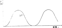
Fig. 6 is that the expression pedal is pedaled the diagram of curves that power changes,
Fig. 7 is the figure that represents power recovery judgement figure with coordinate.
Below, with reference to Fig. 1~Fig. 7 one embodiment of the present of invention are described.
Each component parts of auxiliary power unit 1 is configured in the confined space that the lid 3 by the auxiliary power unit on the auxiliary power unit casing 2 in left side and right side surrounds, and this auxiliary power unit 1 is installed with frame O with being integral.
Can freely dismantle at the two ends of axis 4, integratedly pedal-rod 5 is installed, the front end of this pedal-rod 5 freely to rotate pivot suspension pedal 6, the left side of axis 4 can be inlaid on the ball-bearing casing 7 of auxiliary power unit casing 2 freely to rotate.
Barrel-contoured hollow torque transmission member 8 can be entrenched on the periphery of axis 4 by needle bearing 9 freely to rotate, and it is adjacent with ball-bearing casing 7, between axis 4 and hollow torque transmission member 8, adorning as the Ratcheting one-way clutch 10 of pedaling the power free-wheel clutch, the right side of hollow torque transmission member 8 can be rabbeted on the lid 3 of auxiliary power unit freely to rotate by ball-bearing casing 11, from the lid 3 of this auxiliary power unit on the right side of right-hand outstanding hollow torque-transfer members 8, rabbeting driving chain wheel 12 by spline, acorn nut 13 is integral the ground screw thread and is combined on the right part of hollow torque transmission member 8.
Even the speed of revolutions of axis 4 is lower than the speed of revolutions of hollow torque transmission member 8, also can make 8 idle running of hollow torque transmission member by Ratcheting one-way clutch 10, axis 4 and pedal 6 can keep halted state.
Reducing gear 16 by ball-bearing casing 22,23 freely to rotate pivot suspension on the lid 3 of auxiliary power unit casing 2 and auxiliary power unit, the swing bearing 21 of Direct Current Motor 20 by ball-bearing casing 24,25 freely to rotate pivot suspension on the lid 3 of the casing 20a of Direct Current Motor 20 and auxiliary power unit.
Owing to be such structure, thereby on the contrary, the revolution of rear wheel 35 can pass to Direct Current Motor 20 by chain 34, driving chain wheel 12, hollow torque transmission member 8, driven gear 15, reducing gear 16, the driven pulley 17 that has tooth, toothed contactless belt 19, the driving pulley 18 that has a tooth, can make Direct Current Motor 20 revolutions forcibly with external force, thereby the electric power that is taken place is reclaimed in the effect of energy starter/generator.
And, on the outer peripheral face of the hollow torque transmission member 8 between Ratcheting one-way clutch 10 and the driven gear 15, the strip 26 of the amorphous magnetic alloy system of reeling with being integral, on the inner peripheral surface of the auxiliary power unit casing 2 of these strip 26 foreign sides, set torque magnetic test coil 27, constituting magnetostrictive torque sensor 28 thus.
Torque magnetic test coil 27 on the hollow torque sensor 8, the torque differences of its left and right sides input torque produces shear deformation on above-mentioned strip 26, detected the variation of the magneto-conductivity of the strip 26 that above-mentioned distortion forms by torque magnetic test coil 27.
On hollow torque transmission member 8, because the input of the boosting power of Direct Current Motor 20 is arranged on the right side of torque magnetic test coil 27 (outgoing side), the Ratcheting one-way clutch 10 that passes on left at torque magnetic test coil 27 is imported the power of pedaling that is applied on the pedal 6, thereby magnetostrictive torque sensor 28 can only detect the power of pedaling of the boosting power part that exceeds Direct Current Motor 20.
On the other hand, shaft speed transducer 29 in the foreign side of Ratcheting one-way clutch 10 is being provided with, and along driven gear 15 car speed sensor 30 are set.
Because the revolution of rear wheel 35 is reflected in the revolution of driven gear 15 by chain 34, driving chain wheel 12, hollow transmission of torque part 8, thereby the speed of a motor vehicle 15 that be provided with along driven gear, that car speed sensor 30 that detect the speed of revolutions of driven gear 15 can detect bicycle O.
Have in the auxiliary power unit 1 of said structure, the control of Direct Current Motor 20 is made by electronic control package ECU40, and Fig. 4 represents the summary situation of this control system.
Have on the ECU40 from above-mentioned magnetostrictive torque sensor 28, the input of shaft speed transducer 29, car speed sensor 30 outputs, control signal is outputed to actuator 41, drive Direct Current Motors 20 by actuator 41.
The electric power of battery 45 is supplied with Direct Current Motor 20 by actuator 41, and main switch 46 is installed on this power supply circuit.
On the other hand, between main switch 46 and actuator 41 the power recovery loop is being set, power recovery switch 47, booster circuit 48, counter-current prevent that the diode 49 of usefulness from series setting.
On the other hand, under certain motoring condition, stop, on the contrary Direct Current Motor 20 come work as driving engine to Direct Current Motor 20 supply capabilities, power recovery switch 47 is connected after, with the electric power that produced by power recovery circuit, it is recovered in battery 45.
The electric power that Direct Current Motor 20 produces is raise by the voltage of booster circuit 48 with it, forms than returning to battery 45 behind the high voltage of the regulation output voltage of battery 45.
Below, the control of this power recovery of explanation.
Fig. 5 represents to make bicycle with the 2 kind descending road traveling necessary inputs different at upward slope road surface, flat road surface, angle of inclination that a certain angle of inclination is arranged of certain speed of a motor vehicle.Representing among the figure:
Because this input value is the value symmetrical with resistance to motion, so it is and square the increasing pro rata of the speed of a motor vehicle.
On the upward slope road surface, even the speed of a motor vehicle is 0km/h, in order to keep 0km/h, also essential input force.
On the descending road surface, under a certain vehicle speed condition, be input as 0; Be lower than under the situation of this speed of a motor vehicle, adding negative input, promptly adding the input of direction of retreat in order to keep this speed of a motor vehicle, necessity.
Under the occasion of the bicycle 0 that has this auxiliary power, the input that makes bicycle running is to be made by the power of manpower and Direct Current Motor 20.
Here, manpower is meant the power of rider's Pedalling 6, owing to be alternately Pedalling 6 of left and right sides pin, thereby the variation of pedaling power F as shown in Figure 6, presents waveform, and 1 cycle was equivalent to axis 4 changes 1 circle.
Maxim Δ F among the power of the pedaling F of this variation is used in the control of Direct Current Motor 20.
This is pedaled power Δ F and is detected by above-mentioned magnetostrictive torque sensor 28, and when carrying out power recovery control, the signal of the power of pedaling Δ F that ECU 40 inputs are detected by this magnetostrictive torque sensor 28 and the vehicle velocity V that detected by car speed sensor 30 is also handled.
ECU 40 is except handling the above-mentioned power of pedaling Δ F and vehicle velocity V, and also from the rate of change dV/dt of vehicle velocity V computing vehicle velocity V of input one by one, i.e. computing acceleration alpha is judged so that power recovery to be provided.
Fig. 7 judges that figure is expressed as the figure of coordinate to power recovery, and transverse axis is represented vehicle velocity V, and longitudinal axis table increases pedals power Δ F.
In Fig. 7, be that power recovery is judged line L, speed of a motor vehicle to upper right side bevelled line
0Being the power recovery lower limit speed of a motor vehicle, is at the pedal power Δ F littler than this power recovery judgement line L, than speed of a motor vehicle at motoring condition
0Under the occasion of the big speed of a motor vehicle, promptly under the occasion that draws on hatching that part of, carry out the power recovery control of Direct Current Motor 20.
Power recovery judgement line L is actually to be used for asking pedals the variation of power Δ F with respect to vehicle velocity V, and the above-mentioned speed of a motor vehicle is to make the bicycle O of the band auxiliary power of present embodiment be in aux. controls, the speed when it is travelled that is formed by Direct Current Motor 20 on flat road surface.
When being in this power recovery and judging the vehicle velocity V on line L and pedal the concerning of power Δ F, fast suitable the travelling that big activation is realized ideal becomes such state ground to control the boosting power of Direct Current Motor 20 on flat road surface.
Therefore, no matter track is to go up a slope or descending,, can irrespectively carry out agreeable travelling with the angle of inclination as long as motoring condition is to judge line L along this power recovery.
Therefore, when a certain descending road traveling, compare pedal pedals under the occasion that power diminishes with the speed of a motor vehicle, promptly pedal power Δ F than judging the little occasion of line L, line motor 20 is converted to the power recovery state and make it produce the effect of the braking force that forms by power recovery, if the identical power of pedaling Δ F is arranged, vehicle velocity V is descended, and judge line L near power recovery.
In the present embodiment, in fact whether power recovery also will be seen acceleration alpha.
Pre-determine this power recovery and judge line L, be stored in 40 li of ECU, ECU40 judges line L contrast to the vehicle velocity V of the power of the pedaling Δ F of the magnetostrictive torque sensor 28 of input one by one output and car speed sensor 30 outputs and power recovery in motion, and whether differentiation is in scope that must power recovery (Fig. 7 beat hatching part).
Promptly, be in the below that power recovery is judged line L even pedal power Δ F, in acceleration alpha is 0 or during negative value, keep certain speed or deceleration regime exactly, when this state,, upset certain speed or the play of slowing down is swashed owing to need not make 20 one-tenth power recovery states of Direct Current Motor, thereby do not carry out power recovery, only when acceleration mode, carry out power recovery.
Pedal power Δ F be in power recovery judge line L below, acceleration alpha on the occasion of the time, because compare pedal to pedal power little and be in the speedup state with the speed of a motor vehicle, on this occasion down, by converting Direct Current Motor 20 to the power recovery state, braking force is had an effect, speedup is made driving stability with suppressing, thus can be near agreeable travelling, and can be the power recovery that produces to battery 45 and charge.
Recited above is to have the power of pedaling to have the power recovery condition of situation (Δ F>0), under the occasion of not pedaling power (Δ F=0), when promptly not having Pedalling 6, only judges whether to carry out power recovery with acceleration alpha.
That is, acceleration alpha be on the occasion of the time (α>0), form the power recovery state, acceleration alpha is 0 or during negative value (α≤0), forms the not coasting state of power recovery state.
Owing to pedal power Δ F=0, acceleration alpha>0th, travel in descending ground-surface situation, be in the state that the speed of a motor vehicle increases gradually, in this case, make 20 one-tenth power recovery states of Direct Current Motor, add braking, control brake operation as far as possible, can form agreeable motoring condition with manual mode.
At this moment, can also be by power recovery and to battery charge.
In addition, pedal the situation of power Δ F=0, acceleration alpha≤0, normally on flat road surface or the very little up occasion of sailing in descending road surface of the gradient, at this moment need not be braked, do not made 20 one-tenth power recovery states of Direct Current Motor, make the rotating shaft 21 of Direct Current Motor 20 form free state, become not bearing load ground coasting state.
Above-mentioned power recovery condition is comprehensive, when pedaling power (Δ F>0), speed of a motor vehicle α with pedal power Δ F and be in and judge line L and vehicle velocity V with power recovery among Fig. 7
0In the cross-hatching part for the boundary, and degree of will speed up α>0 is as the power recovery condition; When not pedaling power (Δ F=0), degree of will speed up α>0 is as the power recovery condition.
Also power recovery can be judged the setting up and down of the position of line L from Fig. 7 with passing.
If power recovery is judged that line L passes upward, then apply the braking that the power recovery by Direct Current Motor forms easily, can obtain the travel sensation heavier than above-mentioned state, but the charging to battery 45 is then more, in contrast, pass downwards, then difficult brake activation can obtain the travel sensation lighter than above-mentioned state.
Because power recovery control setup of the present invention is according to the speed of a motor vehicle and pedals the essentiality that power is judged power recovery, thereby pedal power and become undue hour and be judged as and need power recovery comparing pedal with the speed of a motor vehicle, by motor being converted to the power recovery state, make motor become the power recovery state, give battery the power recovery that motor produces as electrical generator, can suppress the electricity consumption of battery, and the braking force that motor is produced as electrical generator acts on the bicycle, can keep agreeable travelling.
Reclaim decision content if set this, then diminish and be lower than when reclaiming decision content comparing treadle effort with the speed of a motor vehicle, can convert motor to the recovery state, can charge battery in conjunction with agreeable motoring condition, and by the braking force effect near agreeable travelling.
Recovery control device is stored the recovery decision content in advance, and (this recovery decision content is under the drive controlling of above-mentioned driving control device, obtain and the corresponding power of pedaling required when flat road surface is travelled of the speed of a motor vehicle), actual detected to the speed of a motor vehicle and pedal power with the storage in the recovery decision content compare after, if actual to pedal force rate power recovery decision content little, then can differentiate for being necessary power recovery, make motor become the power recovery state, battery is charged, and the same agreeable travelling on flat road surface that can irrespectively be held in the state in downhill path and travel.
Pedaling under the little occasion of the above-mentioned power recovery decision content of force rate of reality, have only acceleration/accel be on the occasion of the time just motor is converted to the power recovery state, when acceleration/accel is zero or negative value, promptly when keeping certain speed or being in deceleration, even compare pedal pedals power and diminishes with the speed of a motor vehicle, also power recovery not before the certain speed state is upset, do not make deceleration because of power recovery further before aggravation, thereby can keep agreeable motoring condition.
Be under zero the situation in the power of pedaling of reality, acceleration/accel on the occasion of the time by motor being converted to the power recovery state, not during Pedalling, only otherwise be in acceleration mode, motor power is reclaimed, and does not make it play brake action, can keep agreeable travelling thus.
Claims (4)
1. power recovery control setup with the bicycle of auxiliary power, it is provided with to produce with the motor that is applied to the corresponding auxiliary force of the power of pedaling on the pedal with to this motor carries out the driving control device of drive controlling, it is characterized in that: be provided with
Detect the vehicle speed detector device of the speed of a motor vehicle of this bicycle;
Detection is applied to the force checking device of pedaling of the power of pedaling on the pedal;
Determine the power recovery decision content of the power of pedaling and the control circuit of being stored corresponding to the speed of a motor vehicle in advance;
According to above-mentioned the vehicle speed detector device speed of a motor vehicle that detects and the power of pedaling of pedaling the force checking device detection, pedal detected actual the pedaling under the little occasion of the above-mentioned power recovery decision content of force rate of force checking device above-mentioned under a certain speed of a motor vehicle, convert said motor to the power recovery state.
2. the power recovery control setup of band motive-force-assisted bicycle as claimed in claim 1, it is characterized in that: above-mentioned power recovery control setup under the drive controlling that forms by above-mentioned driving control device, corresponding to the speed of a motor vehicle obtain the needed power of pedaling of travelling on flat road surface in advance, it as above-mentioned power recovery decision content and stored, above-mentioned actual the pedaling under the little occasion of the above-mentioned power recovery of the force rate value of declaring of pedaling the force checking device detection under a certain speed of a motor vehicle converts said motor to the power recovery state.
3. the power recovery control setup of the bicycle of band auxiliary power as claimed in claim 2, it is characterized in that: above-mentioned power recovery control setup is according to the detected speed of a motor vehicle variation of above-mentioned vehicle speed detector device computing acceleration/accel, above-mentioned actual pedaling under the little occasion of the above-mentioned power recovery decision content of force rate, only above-mentioned acceleration/accel be on the occasion of the time, said motor is converted to the power recovery state.
4. the power recovery control setup of the bicycle of band auxiliary power as claimed in claim 3, it is characterized in that: to pedal the actual power of pedaling that force checking device detects be under zero the occasion above-mentioned, above-mentioned acceleration/accel be on the occasion of the time, above-mentioned power recovery control setup converts said motor to the power recovery state.
Applications Claiming Priority (2)
| Application Number | Priority Date | Filing Date | Title |
|---|---|---|---|
| JP103646/96 | 1996-03-29 | ||
| JP10364696A JP3642364B2 (en) | 1996-03-29 | 1996-03-29 | Bicycle regeneration control device with auxiliary power |
Publications (2)
| Publication Number | Publication Date |
|---|---|
| CN1164495A CN1164495A (en) | 1997-11-12 |
| CN1078555C true CN1078555C (en) | 2002-01-30 |
Family
ID=14359547
Family Applications (1)
| Application Number | Title | Priority Date | Filing Date |
|---|---|---|---|
| CN97103389A Expired - Fee Related CN1078555C (en) | 1996-03-29 | 1997-03-27 | Regenerating control device for bicycle with auxiliary power |
Country Status (6)
| Country | Link |
|---|---|
| EP (1) | EP0798204B1 (en) |
| JP (1) | JP3642364B2 (en) |
| CN (1) | CN1078555C (en) |
| DE (1) | DE69701586T2 (en) |
| ES (1) | ES2145528T3 (en) |
| TW (1) | TW419428B (en) |
Cited By (1)
| Publication number | Priority date | Publication date | Assignee | Title |
|---|---|---|---|---|
| CN106043581A (en) * | 2012-12-17 | 2016-10-26 | 雅马哈发动机株式会社 | Driving unit and electric assist bicycle |
Families Citing this family (46)
| Publication number | Priority date | Publication date | Assignee | Title |
|---|---|---|---|---|
| CN2315041Y (en) * | 1997-11-14 | 1999-04-21 | 清华大学 | Intelligent electric tricycle |
| US6152250A (en) * | 1998-07-07 | 2000-11-28 | Shu-Hsien; Li | Power driving control system of electrically-assisted bicycle |
| JP2000118477A (en) * | 1998-10-12 | 2000-04-25 | Sony Corp | Bicycle with assistance function |
| JP4608764B2 (en) * | 2000-11-17 | 2011-01-12 | パナソニック株式会社 | Control method for vehicle with auxiliary power unit |
| ATE377554T1 (en) | 2001-02-28 | 2007-11-15 | Honda Motor Co Ltd | CONTROL DEVICE FOR BICYCLE WITH AUXILIARY MOTOR |
| NL1018948C2 (en) * | 2001-09-13 | 2003-03-20 | Sparta B V | Bicycle with auxiliary drive. |
| JP3882993B2 (en) * | 2001-11-02 | 2007-02-21 | 本田技研工業株式会社 | Regenerative control device for electric vehicle |
| JP2003231491A (en) | 2002-02-08 | 2003-08-19 | Sunstar Eng Inc | Power-assisted bicycle providing aerobic exercise |
| JP2005014869A (en) * | 2003-06-24 | 2005-01-20 | Meiden Eco Drive Kk | Method for controlling assist motor of power-assisted bicycle |
| JP2006015887A (en) * | 2004-07-02 | 2006-01-19 | Sanyo Electric Co Ltd | Motor-assisted bicycle |
| EP1799538A4 (en) * | 2004-09-14 | 2010-10-06 | Systemes D En Et Propulsion Ep | Energy management system for motor-assisted user-propelled vehicles |
| JP2008044414A (en) * | 2006-08-11 | 2008-02-28 | Sanyo Electric Co Ltd | Electrically assisted bicycle |
| ES1070498Y (en) * | 2009-06-30 | 2009-12-02 | Siempre En Bici S L | MOTOR SHAFT MECHANISM, FOR ALL TYPES OF PEDAL AND MOTOR DRIVEN VEHICLES |
| WO2011019743A1 (en) * | 2009-08-10 | 2011-02-17 | Michael Krieger | Motorized bicycle with trainer mode |
| JP5537994B2 (en) * | 2010-03-01 | 2014-07-02 | 三洋電機株式会社 | Electric assist bicycle |
| DE102010009649B4 (en) * | 2010-03-02 | 2017-01-05 | Karlheinz Nicolai | Bicycle with electric auxiliary drive |
| JP5174855B2 (en) * | 2010-06-11 | 2013-04-03 | 株式会社シマノ | Electric motor control system for bicycles |
| JP4906982B1 (en) * | 2010-07-27 | 2012-03-28 | パナソニック株式会社 | Electric bicycle |
| JP5649374B2 (en) | 2010-08-30 | 2015-01-07 | 本田技研工業株式会社 | Bicycle with auxiliary power unit |
| JP2012051446A (en) * | 2010-08-31 | 2012-03-15 | Honda Motor Co Ltd | Bicycle with auxiliary power unit |
| JP5564390B2 (en) * | 2010-09-30 | 2014-07-30 | 本田技研工業株式会社 | Control device for battery-assisted bicycle |
| JP5564391B2 (en) * | 2010-09-30 | 2014-07-30 | 本田技研工業株式会社 | Control device for battery-assisted bicycle |
| JP5479291B2 (en) * | 2010-09-30 | 2014-04-23 | 本田技研工業株式会社 | Control device for battery-assisted bicycle |
| JP5564389B2 (en) * | 2010-09-30 | 2014-07-30 | 本田技研工業株式会社 | Control device for battery-assisted bicycle |
| JP5211181B2 (en) * | 2011-01-14 | 2013-06-12 | 三洋電機株式会社 | Electric assist bicycle |
| IT1404164B1 (en) * | 2011-02-03 | 2013-11-15 | Milano Politecnico | ELECTRICALLY ASSISTED RIDING BICYCLE |
| JP2012214151A (en) * | 2011-03-31 | 2012-11-08 | Honda Motor Co Ltd | Assistive power control apparatus for motor-assisted bicycle |
| JP5373946B1 (en) * | 2012-08-17 | 2013-12-18 | 株式会社シマノ | Bicycle drive unit |
| CN103072493A (en) * | 2011-10-26 | 2013-05-01 | 华创车电技术中心股份有限公司 | Downhill constant-speed electric power back-charging system |
| JP5470358B2 (en) * | 2011-11-29 | 2014-04-16 | 本田技研工業株式会社 | Magnetostrictive torque sensor, electrically assisted bicycle and electric power steering apparatus equipped with this magnetostrictive torque sensor |
| JP2013209077A (en) * | 2012-02-27 | 2013-10-10 | Honda Motor Co Ltd | Power-assisted bicycle |
| JP5919060B2 (en) * | 2012-03-30 | 2016-05-18 | 本田技研工業株式会社 | Bicycle with auxiliary power |
| EP2868562A4 (en) * | 2012-06-28 | 2016-03-02 | Murata Manufacturing Co | Control device of auxiliary-powered movement device, and auxiliary-powered movement device comprising said control device |
| CN104010936B (en) * | 2012-12-17 | 2016-08-24 | 雅马哈发动机株式会社 | Driver element and electric assisted bicycle |
| US9896153B2 (en) | 2013-06-14 | 2018-02-20 | Microspace Corporation | Motor driving control apparatus |
| JP5887386B2 (en) * | 2014-08-01 | 2016-03-16 | ヤマハ発動機株式会社 | Electric bicycle drive device |
| US9771124B2 (en) * | 2015-02-25 | 2017-09-26 | Ford Global Technologies, Llc | Wheel rim-mounted regeneration coil-magnet system |
| US9676443B2 (en) | 2015-03-02 | 2017-06-13 | Ford Global Technologies, Llc | Removable powerpack and seat for a bicycle |
| DE102015203896A1 (en) * | 2015-03-05 | 2016-09-08 | Robert Bosch Gmbh | Drive for a pedal-driven vehicle |
| US9845133B2 (en) | 2015-04-16 | 2017-12-19 | Ford Global Technologies, Llc | Electric bike motor using sensed air speed |
| JP6381573B2 (en) * | 2015-11-09 | 2018-08-29 | 太陽誘電株式会社 | Electric motor regeneration control device, electric motor regeneration drive device, and electric auxiliary vehicle |
| TWI613121B (en) * | 2016-11-11 | 2018-02-01 | 達方電子股份有限公司 | Crank drive apparatus for power assisted bicycle |
| CN109050641B (en) * | 2018-07-16 | 2021-05-07 | 诸葛小莲 | Power cable winding and unwinding vehicle |
| DE102020201212B4 (en) * | 2020-01-31 | 2021-10-07 | Gerd Scheying | Device for energy recovery in two-wheelers with a mid-engine drive unit and method for operating the same |
| CN114212178B (en) * | 2022-02-22 | 2022-05-13 | 品上佳自行车(深圳)有限公司 | Power device of new energy electric bicycle |
| CN115214835B (en) * | 2022-06-29 | 2023-08-01 | 广东高标电子科技有限公司 | Starting control method of electric power-assisted vehicle and electric power-assisted vehicle |
Citations (4)
| Publication number | Priority date | Publication date | Assignee | Title |
|---|---|---|---|---|
| US4111274A (en) * | 1975-08-11 | 1978-09-05 | M. Dale King | Electrically-powered tricycle |
| DE4229261C1 (en) * | 1992-09-02 | 1994-03-31 | August Mutter | Electric generator for bicycle or individual wheel with rotor at rotatable wheel - equipped with permanent magnets and stator formed by coil system for receiving induced voltage is fixed on wheel spindle and generator can be used as servo motor |
| JPH07149280A (en) * | 1993-11-26 | 1995-06-13 | Koyo Seiko Co Ltd | Bicycle having electric motor |
| CN1127199A (en) * | 1994-09-29 | 1996-07-24 | 精工爱普生株式会社 | Travelling control apparatus for electric automobiles |
Family Cites Families (2)
| Publication number | Priority date | Publication date | Assignee | Title |
|---|---|---|---|---|
| JP3086475B2 (en) * | 1990-08-16 | 2000-09-11 | ヤマハ発動機株式会社 | Manual drive with electric motor |
| JPH06321170A (en) * | 1993-05-15 | 1994-11-22 | Toyo Bussan Kk | Electric motor device also used as generator, and bicycle or tricycle with electric motor device also used as generator |
-
1996
- 1996-03-29 JP JP10364696A patent/JP3642364B2/en not_active Expired - Fee Related
-
1997
- 1997-02-04 TW TW086101307A patent/TW419428B/en not_active IP Right Cessation
- 1997-03-18 EP EP97104635A patent/EP0798204B1/en not_active Expired - Lifetime
- 1997-03-18 DE DE69701586T patent/DE69701586T2/en not_active Expired - Fee Related
- 1997-03-18 ES ES97104635T patent/ES2145528T3/en not_active Expired - Lifetime
- 1997-03-27 CN CN97103389A patent/CN1078555C/en not_active Expired - Fee Related
Patent Citations (4)
| Publication number | Priority date | Publication date | Assignee | Title |
|---|---|---|---|---|
| US4111274A (en) * | 1975-08-11 | 1978-09-05 | M. Dale King | Electrically-powered tricycle |
| DE4229261C1 (en) * | 1992-09-02 | 1994-03-31 | August Mutter | Electric generator for bicycle or individual wheel with rotor at rotatable wheel - equipped with permanent magnets and stator formed by coil system for receiving induced voltage is fixed on wheel spindle and generator can be used as servo motor |
| JPH07149280A (en) * | 1993-11-26 | 1995-06-13 | Koyo Seiko Co Ltd | Bicycle having electric motor |
| CN1127199A (en) * | 1994-09-29 | 1996-07-24 | 精工爱普生株式会社 | Travelling control apparatus for electric automobiles |
Cited By (2)
| Publication number | Priority date | Publication date | Assignee | Title |
|---|---|---|---|---|
| CN106043581A (en) * | 2012-12-17 | 2016-10-26 | 雅马哈发动机株式会社 | Driving unit and electric assist bicycle |
| CN106043581B (en) * | 2012-12-17 | 2019-01-01 | 雅马哈发动机株式会社 | Driving unit and electrically assisted bicycle |
Also Published As
| Publication number | Publication date |
|---|---|
| ES2145528T3 (en) | 2000-07-01 |
| EP0798204B1 (en) | 2000-04-05 |
| CN1164495A (en) | 1997-11-12 |
| JPH09267790A (en) | 1997-10-14 |
| TW419428B (en) | 2001-01-21 |
| EP0798204A1 (en) | 1997-10-01 |
| JP3642364B2 (en) | 2005-04-27 |
| DE69701586D1 (en) | 2000-05-11 |
| DE69701586T2 (en) | 2000-08-03 |
Similar Documents
| Publication | Publication Date | Title |
|---|---|---|
| CN1078555C (en) | Regenerating control device for bicycle with auxiliary power | |
| US20230062161A1 (en) | Electric bicycle | |
| CN100349770C (en) | Drive control apparatus and method for vehicles | |
| JP3720316B2 (en) | Electric vehicle drive system | |
| CN1241783C (en) | Electric bicycle | |
| CN1154597C (en) | Electric bicycle | |
| CN101041354A (en) | Vehicle control unit and vehicle | |
| CN1162549A (en) | Assist power control device for power-assisted vehicle | |
| CN100335355C (en) | Motor-driven bicycle | |
| CN1316352A (en) | Running speed control device for light electrically-propelled vehicle and light electrically-propelled vehicle | |
| CN101037090A (en) | Vehicle brake device and method for braking vehicles | |
| CN1927609A (en) | Motor driving system with speed adaptation capability and controlling method thereof | |
| CN1157245A (en) | Electrically assisted vehicle | |
| CN1205954A (en) | Auxiliary propulsion-unit control device for use in electric auxiliary bike | |
| CN103370220A (en) | Control apparatus for vehicle | |
| KR101542103B1 (en) | Driving control method of electric motorcycles | |
| CN1675084A (en) | Vehicle using automatic inertia traveling apparatus | |
| CN101157374A (en) | Mixed dynamical motorcycle | |
| JP5537994B2 (en) | Electric assist bicycle | |
| CN106523167A (en) | Vehicle, system, and method of calculating an engine torque request value | |
| CN1159187C (en) | Auxiliary power driven vehicle | |
| JP3138014B2 (en) | Motor control device for electric motorcycle | |
| WO2023281846A1 (en) | Motor control device for electrically assisted vehicle, and electrically assisted vehicle | |
| JP7195288B2 (en) | Motor drive control device and electrically assisted vehicle | |
| CN2254059Y (en) | Electrically driven stepless speed variation bicycle |
Legal Events
| Date | Code | Title | Description |
|---|---|---|---|
| C10 | Entry into substantive examination | ||
| SE01 | Entry into force of request for substantive examination | ||
| C06 | Publication | ||
| PB01 | Publication | ||
| C14 | Grant of patent or utility model | ||
| GR01 | Patent grant | ||
| C19 | Lapse of patent right due to non-payment of the annual fee | ||
| CF01 | Termination of patent right due to non-payment of annual fee |