CN107819339B - Charge mode creating device, charge control device, charge mode creating method, and power storage system - Google Patents
Charge mode creating device, charge control device, charge mode creating method, and power storage system Download PDFInfo
- Publication number
- CN107819339B CN107819339B CN201710111890.7A CN201710111890A CN107819339B CN 107819339 B CN107819339 B CN 107819339B CN 201710111890 A CN201710111890 A CN 201710111890A CN 107819339 B CN107819339 B CN 107819339B
- Authority
- CN
- China
- Prior art keywords
- battery
- charging
- charge
- value
- upper limit
- Prior art date
- Legal status (The legal status is an assumption and is not a legal conclusion. Google has not performed a legal analysis and makes no representation as to the accuracy of the status listed.)
- Active
Links
Images


Classifications
-
- H—ELECTRICITY
- H02—GENERATION; CONVERSION OR DISTRIBUTION OF ELECTRIC POWER
- H02J—CIRCUIT ARRANGEMENTS OR SYSTEMS FOR SUPPLYING OR DISTRIBUTING ELECTRIC POWER; SYSTEMS FOR STORING ELECTRIC ENERGY
- H02J7/00—Circuit arrangements for charging or depolarising batteries or for supplying loads from batteries
- H02J7/007—Regulation of charging or discharging current or voltage
-
- H—ELECTRICITY
- H02—GENERATION; CONVERSION OR DISTRIBUTION OF ELECTRIC POWER
- H02J—CIRCUIT ARRANGEMENTS OR SYSTEMS FOR SUPPLYING OR DISTRIBUTING ELECTRIC POWER; SYSTEMS FOR STORING ELECTRIC ENERGY
- H02J7/00—Circuit arrangements for charging or depolarising batteries or for supplying loads from batteries
- H02J7/00032—Circuit arrangements for charging or depolarising batteries or for supplying loads from batteries characterised by data exchange
- H02J7/00038—Circuit arrangements for charging or depolarising batteries or for supplying loads from batteries characterised by data exchange using passive battery identification means, e.g. resistors or capacitors
- H02J7/00041—Circuit arrangements for charging or depolarising batteries or for supplying loads from batteries characterised by data exchange using passive battery identification means, e.g. resistors or capacitors in response to measured battery parameters, e.g. voltage, current or temperature profile
-
- H—ELECTRICITY
- H02—GENERATION; CONVERSION OR DISTRIBUTION OF ELECTRIC POWER
- H02J—CIRCUIT ARRANGEMENTS OR SYSTEMS FOR SUPPLYING OR DISTRIBUTING ELECTRIC POWER; SYSTEMS FOR STORING ELECTRIC ENERGY
- H02J7/00—Circuit arrangements for charging or depolarising batteries or for supplying loads from batteries
- H02J7/00047—Circuit arrangements for charging or depolarising batteries or for supplying loads from batteries with provisions for charging different types of batteries
-
- H—ELECTRICITY
- H01—ELECTRIC ELEMENTS
- H01M—PROCESSES OR MEANS, e.g. BATTERIES, FOR THE DIRECT CONVERSION OF CHEMICAL ENERGY INTO ELECTRICAL ENERGY
- H01M10/00—Secondary cells; Manufacture thereof
- H01M10/42—Methods or arrangements for servicing or maintenance of secondary cells or secondary half-cells
- H01M10/425—Structural combination with electronic components, e.g. electronic circuits integrated to the outside of the casing
-
- H—ELECTRICITY
- H01—ELECTRIC ELEMENTS
- H01M—PROCESSES OR MEANS, e.g. BATTERIES, FOR THE DIRECT CONVERSION OF CHEMICAL ENERGY INTO ELECTRICAL ENERGY
- H01M10/00—Secondary cells; Manufacture thereof
- H01M10/42—Methods or arrangements for servicing or maintenance of secondary cells or secondary half-cells
- H01M10/44—Methods for charging or discharging
- H01M10/446—Initial charging measures
-
- H—ELECTRICITY
- H01—ELECTRIC ELEMENTS
- H01M—PROCESSES OR MEANS, e.g. BATTERIES, FOR THE DIRECT CONVERSION OF CHEMICAL ENERGY INTO ELECTRICAL ENERGY
- H01M10/00—Secondary cells; Manufacture thereof
- H01M10/42—Methods or arrangements for servicing or maintenance of secondary cells or secondary half-cells
- H01M10/46—Accumulators structurally combined with charging apparatus
-
- H—ELECTRICITY
- H01—ELECTRIC ELEMENTS
- H01M—PROCESSES OR MEANS, e.g. BATTERIES, FOR THE DIRECT CONVERSION OF CHEMICAL ENERGY INTO ELECTRICAL ENERGY
- H01M10/00—Secondary cells; Manufacture thereof
- H01M10/42—Methods or arrangements for servicing or maintenance of secondary cells or secondary half-cells
- H01M10/425—Structural combination with electronic components, e.g. electronic circuits integrated to the outside of the casing
- H01M2010/4271—Battery management systems including electronic circuits, e.g. control of current or voltage to keep battery in healthy state, cell balancing
-
- H—ELECTRICITY
- H01—ELECTRIC ELEMENTS
- H01M—PROCESSES OR MEANS, e.g. BATTERIES, FOR THE DIRECT CONVERSION OF CHEMICAL ENERGY INTO ELECTRICAL ENERGY
- H01M10/00—Secondary cells; Manufacture thereof
- H01M10/42—Methods or arrangements for servicing or maintenance of secondary cells or secondary half-cells
- H01M10/425—Structural combination with electronic components, e.g. electronic circuits integrated to the outside of the casing
- H01M2010/4278—Systems for data transfer from batteries, e.g. transfer of battery parameters to a controller, data transferred between battery controller and main controller
-
- H—ELECTRICITY
- H01—ELECTRIC ELEMENTS
- H01M—PROCESSES OR MEANS, e.g. BATTERIES, FOR THE DIRECT CONVERSION OF CHEMICAL ENERGY INTO ELECTRICAL ENERGY
- H01M2220/00—Batteries for particular applications
- H01M2220/20—Batteries in motive systems, e.g. vehicle, ship, plane
-
- H—ELECTRICITY
- H01—ELECTRIC ELEMENTS
- H01M—PROCESSES OR MEANS, e.g. BATTERIES, FOR THE DIRECT CONVERSION OF CHEMICAL ENERGY INTO ELECTRICAL ENERGY
- H01M2220/00—Batteries for particular applications
- H01M2220/30—Batteries in portable systems, e.g. mobile phone, laptop
-
- Y—GENERAL TAGGING OF NEW TECHNOLOGICAL DEVELOPMENTS; GENERAL TAGGING OF CROSS-SECTIONAL TECHNOLOGIES SPANNING OVER SEVERAL SECTIONS OF THE IPC; TECHNICAL SUBJECTS COVERED BY FORMER USPC CROSS-REFERENCE ART COLLECTIONS [XRACs] AND DIGESTS
- Y02—TECHNOLOGIES OR APPLICATIONS FOR MITIGATION OR ADAPTATION AGAINST CLIMATE CHANGE
- Y02E—REDUCTION OF GREENHOUSE GAS [GHG] EMISSIONS, RELATED TO ENERGY GENERATION, TRANSMISSION OR DISTRIBUTION
- Y02E60/00—Enabling technologies; Technologies with a potential or indirect contribution to GHG emissions mitigation
- Y02E60/10—Energy storage using batteries
Abstract
The invention relates to a charging mode creating device, a charging control device, a charging mode creating method, and an electric power storage system. The value of the current for charging the secondary battery is calculated while considering the deterioration of the secondary battery, based on the voltage and the current of the secondary battery. The charge control device of the embodiment controls the charging of the secondary battery to be charged based on a charge pattern calculated from a degradation model or a degradation map of the secondary battery and internal state parameters of the secondary battery to be charged. The charging mode is updated based on the change of the internal state parameter.
Description
This application is based on Japanese patent application 2016-. This application incorporates by reference the entirety of this application.
Technical Field
Embodiments of the present invention relate to a charging mode creation device, a charging control device, a charging mode creation method, and an electric storage system.
Background
With the miniaturization of information-related devices, communication devices, and the like, lithium ion secondary batteries having high energy density and capable of achieving reduction in size and weight have become widespread as power sources for these devices. In addition, secondary batteries are also attracting attention in the fields of Electric Vehicles (EV) and natural energy power generation. Along with this, the desire for rapid charging to shorten the charging time of the secondary battery is also increasing.
As a charging method of the secondary battery, a charging method based on a constant current or a constant electric power is performed. In this charging method, for example, the secondary battery is charged with a constant current before the secondary battery reaches a set constant voltage, and the value of the current is controlled so as to maintain the set constant voltage after the secondary battery reaches the set constant voltage.
In the case of performing the rapid charging by the above charging method, it is conceivable to set the constant current value to be high during the period in which the charging is performed at the constant current (constant current charging interval). However, if the current value is high, the battery performance of the secondary battery, such as the battery capacity and the internal resistance, is significantly degraded. Further, since the deterioration of the battery is accelerated, there is also a problem that the life of the battery is shortened.
In order to prevent the life of the battery from being shortened, a method of adjusting the value of the constant current based on the characteristics of the secondary battery is known. For example, the following methods are known: the constant current charging interval is divided into a plurality of intervals based on the internal resistance of the electrode of the secondary battery, and the value of the constant current is adjusted in each interval. However, since the characteristics of the electrodes such as internal resistance change with use, if the battery characteristics are not accurately grasped, not only the efficiency of rapid charging is reduced, but also the deterioration of the battery may be accelerated. Further, a high-difficulty process for measuring the internal resistance is required, which causes a problem of an increase in the process load and an increase in the size of the apparatus. Alternatively, in order to perform measurement using an external device, the secondary battery is troublesome to detach.
Disclosure of Invention
The charge control device of an embodiment controls the charging of the secondary battery to be charged based on a charge pattern calculated based on a degradation model or a degradation map of the secondary battery and an internal state parameter of the secondary battery to be charged, wherein the charge pattern is updated based on a change in the internal state parameter.
According to the charge control device configured as described above, the value of the current for charging the secondary battery can be calculated while considering the deterioration of the secondary battery based on the voltage and the current of the secondary battery.
Drawings
Fig. 1 is a block diagram showing an example of a schematic configuration of a power storage system including a charge control device according to a first embodiment.
Fig. 2 is a diagram showing an example of a flowchart of a schematic process of the charge control device.
Fig. 3 is a diagram showing an example of data on current and voltage during charging.
Fig. 4 is a diagram showing an example of a flowchart of the processing of the internal state parameter calculation unit.
Fig. 5 is a diagram showing an example of a flowchart showing a flow of processing of the battery characteristic calculating unit.
Fig. 6 is a diagram showing an example of a graph (charge amount-OCV curve) showing a relationship between a charge amount and an open circuit voltage.
Fig. 7 is a diagram showing an example of a graph (SOC-OCV curve) showing a relationship between SOC and open circuit voltage.
Fig. 8 is a diagram showing an example of the relationship between the SOC and the reaction resistance Rct at each temperature.
Fig. 9 is a diagram illustrating each resistance component.
Fig. 10 is a diagram illustrating a degradation model.
Fig. 11 is a diagram illustrating a degradation map.
Fig. 12 is a diagram illustrating calculation of the upper limit value of the charging current.
Fig. 13 is a diagram illustrating calculation of the charge mode.
Fig. 14 is a diagram showing an example of a flowchart of the charge mode calculation process.
Fig. 15 is a diagram showing an example of a flowchart of the charging mode update process.
Fig. 16 is a block diagram showing an example of a schematic configuration of the power storage system according to the second embodiment.
Fig. 17 is a diagram showing an example of a flowchart of the degradation information acquisition process.
Fig. 18 is a block diagram showing an example of the hardware configuration of the embodiment.
Description of the symbols
1 accumulator
2 charging control device
21 charge/discharge control part
22 measuring part
23 SOC estimation unit
24 storage section
25 battery characteristic estimating unit
251 charge/discharge history recording unit
252 internal state parameter calculating section
253 battery characteristic calculating part
26 internal resistance correction unit
27 charging mode creating part
271 deterioration information storage unit
272 deterioration information acquisition unit (reference data acquisition unit)
273 upper limit data calculating part
274 charging mode calculating part
3 external database
4 degradation information providing server
5 communication network
6 computer device
61 processor
62 main storage device
63 auxiliary storage device
64 network interface
65 device interface
66 bus
7 external storage medium
Detailed Description
Hereinafter, embodiments will be described with reference to the drawings.
(first embodiment)
Fig. 1 is a block diagram showing an example of a schematic configuration of a power storage system including a charge control device according to a first embodiment. The present power storage system includes a battery 1 (first battery) and a charge control device 2. The Charge control device 2 includes a Charge/discharge control unit 21, a measurement unit 22, an SOC (State of Charge) estimation unit 23, a storage unit 24, a battery characteristic estimation unit 25, an internal resistance correction unit 26, and a Charge mode creation unit 27. The battery characteristic estimating unit 25 includes a charge/discharge history recording unit 251, an internal state parameter calculating unit 252, and a battery characteristic calculating unit 253. The charge pattern creation unit 27 includes a degradation information storage unit 271, a degradation information acquisition unit (reference data acquisition unit) 272, an upper limit data calculation unit 273, and a charge pattern calculation unit 274.
The charge control device 2 may be implemented as a single battery 1 by implementing the charge control device 2 by a CPU circuit or the like and attaching the charge control device to the battery 1.
The battery 1 is a battery to be charged by the charge control device 2. The battery 1 may be a unit cell (single cell), or may include one or more battery packs. Each battery pack may include one or more battery modules. Each battery module may include a plurality of unit cells. The number of battery modules included in each battery pack may be the same or different. The number of unit cells included in each battery module may be the same or different.
The unit cell may be a secondary battery that can be charged and discharged. Here, the description will be given assuming a lithium-ion secondary battery.
In the following description, the expression "storage battery" includes a battery pack, a battery module, and a unit cell, unless otherwise specified.
The battery 1 may be a battery of a device equipped with a battery, such as a mobile phone, a notebook computer, an electric bicycle, an electric vehicle, or an unmanned aerial vehicle. Further, for example, a stationary battery may be provided for each building such as a personal residence, a building, and a factory. The battery may be a battery that is linked to the power generation system or a battery that is interconnected to the system.
The charge control device 2 controls charging and discharging of the battery 1. Further, the state of the connected battery 1 is also estimated. Specifically, the storage battery 1 is charged and discharged, and the internal state parameters and the battery characteristics, which are information on the state of the storage battery 1, are estimated based on data of voltage and current measured during the charging and discharging. The internal state parameters and the battery characteristics will be described later.
Although there is a method of predicting the state of the battery 1 based on the frequency of use or the number of uses, the state of the battery varies depending on the use environment, the load, and the like even if the frequency of use or the number of uses is the same. Therefore, in order to predict the state of the storage battery 1 with high accuracy, the charge control device 2 predicts the state or performance of the storage battery 1 from the measurement values of the tests such as charging and discharging.
Further, the charge control device 2 creates a charge pattern corresponding to the state of the storage battery 1. The charge mode is assumed to be a value indicating a current flowing to the battery 1 to charge the battery 1. That is, the charge mode indicates a restriction condition when the battery 1 is charged. The current flowing for charging is referred to as a charging current. Then, the charge control device 2 charges the storage battery 1 based on the calculated charge pattern.
As a result of the battery 1 being used, the state changes. Due to this change in state, the performance of the battery 1 deteriorates. When the battery 1 after deterioration is charged in accordance with the charging mode before deterioration of the battery 1, not only the charging efficiency is lowered but also deterioration of the battery 1 may be accelerated. Therefore, it is necessary to calculate a charge pattern suitable for the battery 1 to be charged, while grasping the state of the battery 1 to be charged. By performing charging according to an appropriate charging method, the charging speed can be increased without promoting deterioration of the battery 1. In addition, the life of the battery 1 can be prevented from being reduced. In addition, under such charging conditions as to accelerate the deterioration of the battery 1, for example, in charging by a large current or charging at a high temperature, the risk of safety such as ignition is increased. The charge pattern calculated in the present embodiment can satisfy the condition of suppressing the rate of deterioration of the battery 1, and can inevitably ensure the safety during charging.
The charge control device 2 uses degradation information (reference data) to perform the calculation process of the charge mode. The deterioration information will be described later. The operation of the charge control device 2 will be described in detail later.
The system configuration described above is an example, and is not limited to the above configuration. For example, although the charge control device 2 includes the storage unit 24 and the degradation information storage unit 271 in fig. 1, the storage unit 24 and the degradation information storage unit 271 may be integrated into one storage unit. The charge control device 2 may be connected to another device or the like, and the charge control device 2 may output the charge mode to the other device. The output methods are not particularly equal. Or a document, mail, image. The internal resistance correction unit 26 may be included in the battery characteristic estimation unit 25.
Each component of the charge control device 2 may be present outside the charge control device 2 as long as it can receive information necessary for processing from the charge control device 2 by communication or an electric signal and transmit the processing result to the charge control device 2. For example, the charging mode creating unit 27 may be a device that exists outside the charging control device 2 as long as it can receive the battery characteristics and the like from the charging control device 2 by communication or an electric signal and transmit the charging mode to the charging control device 2.
Fig. 2 is a diagram showing an example of a flowchart of a schematic process of the charge control device. Fig. 2(a) is a process for grasping the state of the battery 1. This processing is performed to grasp the state of the battery 1 that has changed due to deterioration or the like, and is assumed to be performed every time a certain period of time has elapsed. Fig. 2(B) is a process for calculating the charging pattern. This processing is assumed to be performed after the processing of fig. 2(a) when the charge mode of the battery 1 is first created or when it is determined that the state of the battery 1 has changed and the charge mode is created again. Further, the timing may be other than the above-described timing.
A process for grasping the state of the battery 1 will be described. The charge control device 2 instructs the battery 1 to charge (or discharge) under a predetermined condition (S101). The charge control device 2 acquires the charge (discharge) result from the battery 1 (S102), and analyzes the charge result (S103). The analysis of the charging result means that the internal state parameters and the battery characteristics (cell characteristics) of each unit battery are calculated based on the charging result. Specifically, the internal state parameters are estimated based on data of current and voltage measured at the time of charging or discharging. Furthermore, the estimation of the battery characteristics is performed based on the internal state parameters.
The internal state parameter indicates the state of the unit battery. The internal state parameters are assumed to include positive electrode capacity (mass of positive electrode), negative electrode capacity (mass of negative electrode), SOC deviation, and internal resistance. The SOC deviation means a difference between the initial charge amount of the positive electrode and the initial charge amount of the negative electrode.
The battery characteristics can be calculated from the internal state parameters, and represent characteristics such as the voltage of the battery 1. The battery characteristics are assumed to include a battery capacity, an Open Circuit Voltage (OCV), an OCV curve, and the like. In addition, the internal resistance may be included in the battery characteristics. The OCV curve means a graph (function) representing a relationship between a certain index relating to the battery and the open circuit voltage. The battery capacity is a range in which the range of the positive electrode capacity overlaps with the range of the negative electrode capacity. When the SOC is 100%, the potential difference between the positive electrode and the negative electrode becomes the end-of-charge voltage of the battery, and when the SOC is 0%, the potential difference between the positive electrode and the negative electrode becomes the end-of-discharge voltage of the battery. As such, the battery capacity can be calculated based on the charge amount.
The process for calculating the charging pattern will be explained. The charge control device 2 acquires the degradation information from the degradation information storage unit 271 (S201). Then, a charge pattern is calculated based on the calculated internal state parameter or the deterioration information on the battery characteristics (cell characteristics), and the specified value of the deterioration rate (S202). Details will be described later. The charge control device 2 charges the battery 1 in accordance with the calculated charge pattern (S203). Thereby, charging is performed by a charging method suitable for the battery 1.
Next, the constituent elements included in the charge control device 2 will be explained.
The charge/discharge control unit 21 instructs the battery 1 to charge and discharge under predetermined conditions. The battery 1 is charged and discharged for measuring internal state parameters. The charge and discharge need to be performed before the change in the state of the storage battery 1 becomes non-negligible due to the progress of the deterioration of the unit cells. Therefore, the charging and discharging are performed for a certain period or at a certain timing that is appropriately determined in consideration of the change in the battery characteristics. The charge/discharge control unit 21 may be configured to give an instruction to charge/discharge when receiving an instruction from a user, another system, or the like via an input unit not shown.
The charge/discharge control unit 21 charges the battery 1 based on the charge pattern created by the charge pattern creation unit 27. The charging control device 2 may charge the storage battery 1 until the charging mode is created, and the charging according to the charging mode may be performed by a device other than the charging control device 2.
The measurement unit 22 measures information about the battery 1. The information measured is: the voltage between the positive electrode terminal and the negative electrode terminal of the unit cell, the current flowing through the unit cell, the temperature of the unit cell, and the like. The measurement data of the measurement unit 22 includes data such as voltage, current, and temperature of the battery 1 measured at the time of charging or discharging the battery 1.
The SOC estimating unit 23 estimates the SOC (state of charge) of the battery 1 at the current time based on the measurement data of the measuring unit 22. The SOC may be estimated using an SOC-OCV curve calculated by the battery characteristic estimating unit 25 based on the current state of the battery 1.
The storage unit 24 stores data used for processing by the battery characteristic estimating unit 25. For example, a function or the like indicating a relationship between the amount of charge and the potential of the positive electrode or the negative electrode of the unit battery is stored. Other data may also be stored.
The battery characteristic estimating unit 25 calculates the internal state parameters and the battery characteristics of the battery 1 at the present time based on the measurement data of the measuring unit 22. In the case where the battery characteristics are not required, the battery characteristics may not be calculated. As described above, the battery characteristics include the battery capacity, the internal resistance, the Open Circuit Voltage (OCV), and the OCV curve. The OCV curve (function) may be a function representing a relationship between an Open Circuit Voltage (OCV) of the secondary battery and a state of charge or an amount of charge charged in the secondary battery, for example. An SOC-OCV table indicating the relationship between SOC and OCV may be used. The charge amount-OCV table may be a relationship between the charge amount and the OCV. The OCV curve to be calculated may be of a predetermined type.
Various battery characteristic measurement methods can be used for calculating the battery characteristics. Specifically, there are a charge/discharge test in which a battery capacity is measured by actually flowing a current, a current suspension method in which an internal resistance value is mainly measured, and electrochemical measurements such as ac impedance measurement. Further, these may be combined to perform measurement. Further, a method of analyzing the charge/discharge curve to easily estimate the battery characteristics may be used.
The internal configuration of the battery characteristic estimating unit 25 will be described.
The charge/discharge history recording unit 251 records data (history) such as voltage, current, and temperature measured by the measuring unit 22 during charging or discharging of the storage battery 1. This recording is repeated at regular time intervals from the start of charging of the battery 1 to the end of charging of the battery 1. The time interval may be set arbitrarily according to the processing using the record. For example, setting to an interval of 0.1 second to 1 second is conceivable. The recorded time may be an absolute time or a relative time from the start of charging. Note that, when the process of the charge/discharge history recording unit 251 is repeated at regular time intervals, the recording of the time may be omitted.
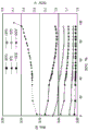
Fig. 3 is a diagram showing an example of data on current and voltage during charging. The data shown in fig. 3 is an example of constant-current constant-voltage charging that is generally used as a method of charging a secondary battery. The broken line in fig. 3 indicates the current history, and the solid line indicates the voltage history.
In the processing of the internal state parameter calculation unit 252 described later, for example, the charging history of the entire constant-current constant-voltage charging or the charging history of only the constant-current charging section (between t0 and t1 in fig. 3) may be used. The charging is not necessarily started from the SOC of 0%, and may be started from the SOC of 20% or the like.
The internal state parameter calculation unit 252 calculates internal state parameters, that is, the amount of active material constituting the positive electrode or negative electrode of the unit cell, the initial charge amount, and the internal resistance of the unit cell, based on the history recorded by the charge/discharge history recording unit 251.
The internal state parameter calculation unit 252 calculates a function of the battery voltage based on the active material amount and the internal resistance. The battery voltage is calculated based on the current data and the voltage data at the time of charging or discharging the battery, and the function. Then, the amount of active material and the internal resistance that reduce the difference between the calculated battery voltage and the measured voltage are determined by regression calculation. In addition, the positive electrode may be composed of a plurality of active materials, but in the present embodiment, a secondary battery in which the positive electrode and the negative electrode are composed of 1 active material will be described as an example.
When a secondary battery in which the positive electrode and the negative electrode are each composed of 1 active material is charged, the voltage (terminal voltage) Vt at time t can be represented by the following equation.
[ formula 1 ]

ItCurrent value q at time ttThe charge amount of the battery at time t is shown. f. ofcIs a function representing the relationship between the amount of charge and the potential of the positive electrode, faIs a function representing the relationship between the amount of charge and the potential of the negative electrode. q. q.so cDenotes the initial charge amount of the positive electrode, McIndicating the mass of the positive electrode. q. q.so aDenotes an initial charge amount of the negative electrode, MaIndicating the mass of the negative electrode. R is the internal resistance.
Current value ItThe current data recorded by the charge/discharge history recording unit 251 is used. By applying a current value ItCalculating the charge amount q by performing time integrationt. Function fcAnd function faIs recorded in the memory as function informationAnd a portion 24.
Initial charge q of other positive electrodeo cMass M of positive electrodecInitial charge amount q of negative electrodeo aMass M of the negative electrodeaAnd 5 values (parameter group) of the internal resistance R are estimated by regression calculation. The active material mass of each pole may be calculated by considering a predetermined ratio of the mass of each pole.
Fig. 4 is a diagram showing an example of a flowchart of the processing of the internal state parameter calculation unit 252. The process of the internal state parameter calculation unit 252 is started after the charging of the battery 1 is completed.
The internal state parameter calculation unit 252 performs initialization, sets an initial value for the parameter set, and sets the number of iterations of regression calculation to 0 (S301). The initial value may be a value calculated when the previous active material amount calculation process was performed, or may be a value obtained by assuming.
The internal state parameter calculation unit 252 calculates a residual E represented by the following equation (S302).
[ formula 2 ]

Vbat_tRepresenting the terminal voltage at time t, tendIndicating the end of charge time
The internal state parameter calculation unit 252 calculates the update step (step size) of the parameter group (S303). The update step size of the parameter set can be calculated using, for example, the Gauss-Newton method, Levenberg-marquardt method, or the like.
The internal state parameter calculation unit 252 determines whether or not the update step size is smaller than a predetermined size (S304). When the update step size is smaller than the predetermined size (no in S304), the internal state parameter calculation unit 252 determines that the calculation is converged and outputs the current parameter group (S307). When the update step size is equal to or larger than a predetermined threshold value (yes in S304), it is checked whether or not the number of repetitions calculated by the regression exceeds a predetermined value (S305).
When the number of iterations calculated by the regression exceeds a predetermined value (yes in S305), the current parameter set is output (S307). When the number of iterations calculated by the regression is equal to or less than the predetermined number (no in S305), the parameter group and the update step calculated in S303 are added, and the number of iterations calculated by the regression is increased by one (S306). Then, the process returns to the calculation of the residual error again (S302). The above is a flowchart showing the flow of the processing of the internal state parameter calculation unit 252.
In the present embodiment, the charge history is used as an input to the internal state parameter calculation unit 252, but the active material amount can be calculated similarly even if the discharge history is used. In the case of using the discharge history, the same flow and parameters as those used in the case of calculating the active material amount using the charge history can be used as the flow and parameters of the processing of the internal state parameter calculation unit 252.
The battery characteristic calculation unit 253 calculates an open circuit voltage, which is a battery characteristic of the battery 1. The battery characteristic calculation unit 253 uses the initial charge q of the positive electrode calculated by the internal state parameter calculation unit 252o cMass M of positive electrodecInitial charge amount q of negative electrodeo aMass M of the negative electrodeaThe relationship between the amount of charge of the battery and the open circuit voltage is calculated.
Fig. 5 is a diagram showing an example of a flowchart showing the flow of the processing of the battery characteristic calculating unit 253. The flowchart starts after the processing of the internal state parameter calculation unit 252 is finished. In this flowchart, the amount of charge q is setnAccording to a certain value Δ qnIncrease or decrease, when the open circuit voltage is found to be lower than the lower limit value to the charge amount q of the lower limit value or moren0When q is greater than qn0As an initial value, let qnEach increment Δ qnUntil the open circuit voltage exceeds the upper limit value, the amount of charge and the open circuit voltage at that time are recorded at each increment. Thus, the relationship between the amount of charge and the open circuit voltage in the range from the lower limit value to the upper limit value of the open circuit voltage can be calculated. Amount of charge qn0The difference from the charged amount qn when the open circuit voltage is the upper limit value becomes the battery capacity.
The battery characteristic calculation unit 253 sets the charge amount qnIs detected (S401). q. q.snThe initial value of (a) may be 0 or a value smaller than 0 by several percent of the rated capacity of the battery 1. Specifically, if the rated capacity of the battery 1 is 1000mAh, it is set to a range of about-50 mAh to 0 mAh.
The battery characteristic calculation unit 253 calculates the open-circuit voltage (S402). The following equation can be used to calculate the open circuit voltage.
[ formula 3 ]

Next, the battery characteristic calculation unit 253 compares the calculated open circuit voltage with a predetermined battery lower limit voltage (S403). The battery lower limit voltage is a value determined by a combination of the positive electrode active material and the negative electrode active material used in the battery 1. Specifically, the voltage of the positive electrode active material and the voltage of the negative electrode active material are determined in appropriate ranges from the viewpoints of safety, life, resistance, and the like, and the lower limit and the upper limit of the range of use of the battery are determined from the combination of these.
When the open circuit voltage is not lower than a predetermined lower limit voltage (no in S403), the amount of charge q is determinednMinus Δ qn(S404), the open circuit voltage is calculated again (S402). When the open circuit voltage is lower than the predetermined lower limit voltage (yes in S403), the battery characteristic calculation unit 253 adds the charge amount qnPlus Δ qn(S405). By these, the amount of charge qnThe lower limit value is approached. Δ q ofnAny value can be set. For example, it is conceivable to set the rated capacity of the battery 1 to about 1/1000 to 1/100. Specifically, if the rated capacity of the battery 1 is 1000mAh, it is considered to be set in a range of about 1mAh to 10 mAh.
The battery characteristic calculating section 253 uses additionThe later charge qn+ΔqnThe open circuit voltage is calculated (S406). Then, the battery characteristic calculation unit 253 compares the calculated open circuit voltage with the lower limit voltage (S407). When the open circuit voltage is lower than the lower limit voltage (no in S407), the process returns to S405, and the amount of charge q is reduced againnPlus Δ qn(S405). When the open circuit voltage is equal to or higher than the lower limit voltage (yes in S407), the open circuit voltage is changed from lower than the lower limit value to equal to or higher than the lower limit value, and therefore the charge amount q at that time is changednIs set to qn0And the amount of charge q is calculatedn0Is recorded together with the open circuit voltage En (S408). The amount of charge q may be setn0The value of (d) is represented as 0 as a reference value. In this case, the slave charge amount q is recorded at the time of the following recordingnIs subtracted by qn0The value obtained after (c).
The battery characteristic calculation unit 253 calculates the amount of charge qnPlus Δ qn(S409) to calculate an open circuit voltage (S410) and record the slave charge amount qnSubtracting qn0The obtained value and the calculated open circuit voltage En (S411).
The battery characteristic calculation unit 253 compares the calculated open circuit voltage with a predetermined upper limit voltage of the storage battery (S412). The upper limit voltage of the battery is a value determined by the combination of the positive electrode active material and the negative electrode active material used in the battery 1. When the open circuit voltage is lower than the predetermined upper limit voltage (no in S412), the process returns to the charge amount qnPlus Δ qnThe process (S409). When the open circuit voltage is equal to or higher than the predetermined upper limit voltage (yes in S412), the process is ended. The above is a flowchart showing the flow of the processing of the battery characteristic calculating unit 253.
Fig. 6 is a diagram showing an example of a graph (charge amount-OCV curve) showing a relationship between a charge amount and an open circuit voltage. Fig. 6(a) is a charge amount-OCV curve in the current state obtained by the battery characteristic calculation unit 253. Fig. 6(B) is a graph in which the vertical axis of the graph shown in fig. 6(a) is set from the lower limit voltage to the upper limit voltage.
Fig. 7 is a diagram showing an example of a graph (SOC-OCV curve) showing a relationship between SOC and open circuit voltage. The point of difference from fig. 6 is that the horizontal axis is not the charge amount but the SOC. Fig. 7 is a graph (solid line) obtained by converting the graph shown in fig. 6(B) into an SOC-OCV curve, and is superimposed on an SOC-OCV curve (broken line) of the battery in the initial state. The broken line in fig. 7 indicates the open circuit voltage of the battery in the initial state, and the solid line indicates the open circuit voltage of the battery after a change (current state) due to deterioration of the battery or the like. The SOC represents a ratio of the amount of charge currently charged to the full charge capacity, and is represented by a value between 0 and 1 or 0 and 100%.
The conversion from the charged amount to the SOC may be performed using the battery capacity and the charged amount calculated from the charged amount-OCV curve. In the description herein, when simply referred to as a state of charge, the SOC includes not only the SOC but also the amount of charge and the like.
The changed curve is such that the length of the curve becomes shorter as the capacity decreases, but as can be seen from fig. 7, not only the length of the curve but also the shape itself changes. For example, when the state of charge (SOC) is estimated based on the open circuit voltage, when the measured open circuit voltage is a, the correct state of charge (current state of charge) is B1. However, when the open circuit voltage curve is considered to be not deformed, that is, when the open circuit voltage is obtained from the SOC-OCV curve in the initial state, the state of charge of the voltage a is obtained as B2, and the estimation accuracy of the state of charge is lowered. Therefore, as in the first embodiment, the SOC-OCV curve in the current state is used, whereby the state of charge can be measured with high accuracy.
The SOC-OCV curve calculated by the battery characteristic estimating unit 25 may be acquired by the SOC estimating unit 23, and the SOC estimating unit 23 may estimate the SOC of the battery 1 based on the SOC-OCV curve.
Therefore, according to the first embodiment, without performing special charging and discharging, etc., the relationship between the charged amount and the open circuit voltage (charged amount-OCV curve or SOC-OCV curve) that changes with use can be accurately grasped, and the state of charge can be estimated with high accuracy.
Note that, although the case where the positive electrode and the negative electrode of the secondary battery are each composed of 1 active material has been described here, the present invention can be similarly applied to a secondary battery in which either the positive electrode or the negative electrode of the secondary battery is composed of a plurality of active materials. In the case where another storage unit that stores the amount of active material of the battery 1 is prepared in advance, the battery characteristic calculation unit 253 can calculate a graph showing the relationship between the charge amount and the open circuit voltage of the secondary battery within a predetermined voltage range of the battery, using the amount of active material stored in the other storage unit.
The battery characteristic calculation unit 253 may calculate other battery characteristics. For example, the voltage, the electric power, or the amount of electric power of the battery 1 may be calculated using the calculated open circuit voltage or the like. The calculation method may be performed using the following calculation formula. C in the following calculation formula represents a predetermined constant.
(Voltage)
Voltage-open circuit voltage-c x internal resistance x current
(electric power)
Electric power-current x open circuit voltage-c x internal resistance x (current)2
(amount of electric Power)
Capacity of battery x average voltage
The internal resistance may be the estimated value calculated by the internal state parameter calculation unit 252, or may be the estimated value corrected by the internal resistance correction unit 26, which will be described later. The battery characteristic calculating unit 253 may recalculate the battery characteristic once calculated, using the estimated value corrected by the internal resistance correcting unit 26. The estimation value calculated by the internal resistance correction unit 26 can improve the accuracy. The current may be obtained from the measurement data of the measurement unit 22. The battery characteristic calculating unit 253 may receive a value of a formula, a constant, or the like necessary for calculation via the storage unit 24 or the like.
The internal resistance correction unit 26 corrects the internal resistance of the current temperature T of the storage battery 1 based on the internal resistance R calculated by the battery characteristic estimation unit 25 and the temperature T measured by the measurement unit 22. The corrected internal resistance Rcr is set. When the internal resistance is not corrected, the internal resistance correction unit 26 may not be provided.
The temperature correction of the internal resistance by the internal resistance correction unit 26 will be described. The temperature correction of the internal resistance means, for example, providing a means for correcting the influence of temperature on the battery performance diagnosis method, and expanding the temperature range in which the battery performance diagnosis can be favorably applied. As described in the processing of the battery characteristic estimating unit 25, the battery performance diagnosing method estimates the battery capacity, the internal resistance, and the degree of deterioration of each active material of the positive and negative electrodes, based on the charge/discharge curve, with reference to the charge amount-OCV data of each active material.
The principles and methods thereof are explained. The lithium ion secondary battery has a positive electrode and a negative electrode facing each other, and an electrolyte containing a Li salt between the positive electrode and the negative electrode. In addition, active materials are applied to the positive electrode and the negative electrode on the current collecting foil. The collector foils are connected to positive and negative terminals mounted outside the battery, respectively. During charge and discharge of the battery, Li ions move between the positive electrode active material and the negative electrode active material via the electrolyte, and electrons flow from the active material to the external terminal.
Each active material has an amount of Li and a potential that can be reversibly inserted or removed. The amount of energy that can be stored in the battery within a certain range of charge and discharge voltage is determined by the amounts of the positive electrode active material and the negative electrode active material in the battery and the combination thereof.
Further, at the time of charge and discharge, there are generated: li ion conduction, charge transfer resistance when Li ions in the electrolyte intrude into the active material, resistance due to a coating formed at the interface between the electrolyte and the active material, and resistance when electrons flow through the active material and the current collecting foil. The internal resistance of the battery is the sum of the movement of Li ions, the movement of electrons, the charge transfer resistance, the resistance of the coating, the diffusion resistance in the positive electrode and the negative electrode, and the like.
In general, in a battery control system inside a lithium ion secondary battery, from the viewpoint of safety, the voltage of each unit battery, the temperature inside the battery pack, and the like are measured. If the battery characteristics can be calculated based on these measurement data, the calculation cost and time can be reduced.
However, it is very difficult to analyze the behavior of the battery in actual use in which the charging and discharging conditions are finely and randomly varied. This is because a complex composite phenomenon such as time-dependent resistance, diffusion resistance, and relaxation process is not easy to calculate and model. On the other hand, if only a simple behavior such as charging of an electric vehicle performed under a certain condition is targeted, analysis can be performed by a simplified model.
Therefore, in the battery performance estimation method according to the present embodiment, based on a curve (curve) of "potential-charge amount" obtained from data (charge-discharge curve) of charge or discharge under a certain condition for Li insertion/desorption reaction of each active material, the value of the variable is determined by fitting calculation using the amount of each active material and the rise (overvoltage) of the battery voltage due to the internal resistance associated with the application of the charge current as variables. This can estimate a decrease in capacity (decrease in the respective active materials) and an increase in internal resistance.
However, in the actual usage state of the storage battery, the temperature condition varies depending on the external environment, the state of the storage battery during charging, and the like. When the temperature of the battery changes, the battery performance also changes. In particular, the internal resistance increases more than the decrease in temperature. Fig. 8 is a diagram showing an example of the relationship between the SOC and the reaction resistance Rct at each temperature. The reaction resistance Rct is one of the components of the internal resistance. As shown in fig. 8, it is understood that the reaction resistance greatly varies depending on the temperature. Therefore, even if the analysis results of the measurement data with different temperatures are compared, the fluctuation of the analysis results due to the temperature has a great influence, and it is difficult to evaluate the increase of the internal resistance due to the deterioration.
Therefore, when the battery characteristics are estimated based on the measurement data of the storage battery in actual use, the accuracy of the battery characteristics can be improved by correcting the internal resistance temperature.
The internal resistance of the battery is composed of a plurality of types of resistance components. The temperature dependence of each resistance component and the increasing speed due to deterioration are different. Therefore, the proportion of the resistance changes due to the progress of the deterioration, and the temperature dependence of the entire internal resistance also changes. In view of this, the internal resistance temperature correction in the battery performance estimation method according to the present embodiment is performed by dividing the internal resistance into 3 components of the reaction resistance Rct, the diffusion resistance Rd, and the ohmic resistance Rohm, correcting the internal resistance to a value corresponding to the reference temperature T0 according to the respective inherent temperature dependencies, and then summing the corrected internal resistance values.
Specifically, the correction from the battery temperature at the time of measurement to the reference temperature is performed by the following equation. In the following formula, Rgas represents a gas constant. T0 represents the reference temperature, and T represents the battery temperature at the time of measurement. R1 represents a constant. Ea. Eb and Ec are constants that determine the temperature dependence of the respective resistance components.
(reaction resistance)
Rct(T0)=Rct(T)×Exp(-Ea/(Rgas·T))/Exp(-Ea/(Rgas·T0))
(diffusion resistance)
Rd(T0)=Rd(T)×Exp(-Eb/(Rgas·T))/Exp(-Eb/(Rgas·T0))
(ohmic resistance)
Rohm(T0)=(Rohm(T)-R1)×Exp(-Ec/(Rgas·T))/Exp(-Ec/(Rgas·T0))+R1
Fig. 9 is a diagram for explaining the resistance components. The ohmic resistance includes an ion conduction resistance of the electrolyte and an electron conduction resistance within the battery. The electron conduction resistance, which has relatively small temperature dependence, is set to be constant. The reaction resistance includes a charge transfer resistance and a resistance of the surface film. The diffusion resistance includes resistance associated with lithium ion diffusion inside the active material and inside the electrode.
Ec of the ohmic resistance represents activation energy associated with movement of Li ions in the electrolyte. Ea of the reaction resistance represents energy when Li ions solvated in the electrolyte are desolvated on the surface of the active material. The Eb of the diffusion resistance is considered as an activation energy accompanying the movement between Li ion sites inside the active material. Therefore, it can be considered that these values are constant and do not change during the deterioration.
The values of Ea, Eb, and Ec can be calculated by measuring ac impedance of the unit cell, measuring current pulse, and the like. The values of Ea, Eb, and Ec relating to the battery to be analyzed are calculated in advance from the measured values and stored in the storage unit 24. Then, the reference may be made at the time of temperature correction calculation of the internal resistance.
Next, a method of calculating the internal resistance by dividing it into 3 components based on the estimation of the battery characteristics of the charge/discharge curve will be described.
In the deterioration process of the battery, 3 components of the internal resistance each rise, but the rate of increase due to deterioration differs depending on each component. Therefore, by limiting the range of the battery life to be evaluated, there is a possibility that the assumption of no degradation is satisfied. For example, in a battery for an electric vehicle, when the lower limit of the evaluation is assumed to be about 90 to 70% of the remaining capacity, some of the resistance components may be approximated to a constant value during the life of the battery, although the evaluation is influenced by the use conditions, the configuration of the battery, and the like.
(first method)
The first method of calculating 3 components from the calculated internal resistance value of the battery is a method of considering the ohmic resistance component and the diffusion resistance component as constant values and considering the residual as a reaction resistance. In this method, it is assumed that the ohmic resistance component and the diffusion resistance component do not increase due to degradation, and only a temperature change depending on the cell temperature is considered. In the analysis of the charge/discharge curve, the ohmic resistance component and the diffusion resistance component at a certain temperature T are subtracted from the internal resistance value estimated for the temperature T, and the remaining value is regarded as the reaction resistance component. Then, the components are temperature-corrected to the reference temperature T0 and summed up, and the internal resistance value at the reference temperature T0 is calculated. The first method is suitable for the following cases: in the case of a slow usage method in which the battery current ratio is small, the temperature is near room temperature or lower in the range of SOC where the positive and negative active materials are stable.
(second method)
The second method is as follows: the ohmic resistance component and the diffused resistance component are estimated from a function relating to the relationship between the 2 resistance components and the accumulated time or the accumulated power amount, respectively, and the residual is used as the reaction resistance. In this method, it is assumed that the deterioration of the ohmic resistance component and the diffusion resistance component is related to time or a charge/discharge cycle amount, and the ohmic resistance component and the diffusion resistance component are calculated. In the analysis of the charge/discharge curve, the calculated ohmic resistance component and diffusion resistance component are subtracted from the internal resistance value estimated for a certain temperature T, and the remaining value is regarded as the reaction resistance component. Then, the components are temperature-corrected to the reference temperature T0 and then summed up, and the internal resistance value at the reference temperature T0 is calculated. The second method is suitable for the following cases: the deterioration of the ohmic resistance component and the diffusion resistance component is relatively small, but it is certainly progressed.
The usage of the accumulated time or the accumulated amount of power may be determined according to the usage environment or the like. For example, when the deterioration of the battery progresses due to the generation of gas during storage or the like, it is preferable to estimate the amount of deterioration based on the accumulated time. On the other hand, when deterioration of the battery due to repetition of cycles of processes such as charging and discharging is significant, such as a change in volume of the active material, it is preferable to estimate the amount of deterioration based on the accumulated electric power.
Further, data of the accumulated time or the accumulated power amount is held in advance. The accumulated amount of electric power may also be replaced by the amount of operation of the apparatus, for example, the travel distance if a vehicle.
(third method)
The third method is as follows: the reaction resistance component and the diffusion resistance component are estimated from the data of the diffusion resistance and the charge amount of each living material held in advance or the data of the reaction resistance and the charge amount, and the residual is regarded as the ohmic resistance component. In the third method, unlike the first and second methods, the following method is used: in the analysis of the charge/discharge curve, the values of the reaction resistance and the diffusion resistance are estimated by performing regression calculation with reference to a reaction resistance-charge amount curve, a diffusion resistance-charge amount curve, or an internal resistance-charge amount curve of the battery of the active material. The resistance component of the active material has a dependency on the charge amount, that is, SOC, and the composition of the internal resistance is estimated from the tendency of the internal resistance-charge amount of the battery by utilizing the fact that the tendency of the dependency does not change even if the dependency is deteriorated.
The reaction resistance-charge amount curve and the diffusion resistance-charge amount curve of the active material need to be measured in advance. Further, the mode of change due to deterioration also differs depending on the configuration of the battery, and therefore, it is necessary to measure in advance. For example, the following forms can be considered: when a resistive surface coating is formed, the internal resistance is uniformly increased by a certain value every time, and when the active material is decreased, the internal resistance is uniformly increased by n times.
The third method is applicable to the case where: the reaction resistance-charge amount significantly changes, and as a result, the dependency of the charge amount appears clearly as the reaction resistance of the battery.
(fourth method)
The fourth method is as follows: a method of estimating a reaction resistance component, an ohmic resistance component, and a diffusion resistance component by performing regression calculation using previously held diffusion resistance-charge amount, reaction resistance-charge amount, and ohmic resistance-charge amount data of each living material. In the third method, only the diffusion resistance-charge amount and the reaction resistance-charge amount are used, but in the fourth method, ohmic resistance-charge amount data is also used. When the dependence of the ohmic resistance on the charge amount of the active material is characterized, it is effective, for example, when the electron conductivity of the active material is largely changed by charge and discharge.
The battery characteristic calculation unit 253 may calculate, as the battery characteristic, an amount of power that can be actually output, using the corrected internal resistance. The amount of electric power that can be actually output can be calculated based on the charge amount-OCV curve, the dischargeable electric amount, and the corrected internal resistance.
The charging pattern creating unit 27 calculates the charging pattern based on the internal state parameter estimated by the battery characteristic estimating unit 25, the estimated value of the battery characteristic, and the specified value of the degradation rate. The value of the charging current in the charging mode is calculated so that the degradation rate due to charging becomes a specified value or less.
The deterioration rate indicates the rate at which the deterioration of the secondary battery progresses. The specified value of the degradation rate may be stored in advance in the degradation information storage unit 271, or may be received from a user or the like via an input unit not shown.
The deterioration information storage unit 271 stores information (data) about deterioration of the secondary battery, which is required when the charge control device 2 calculates the charge mode of the storage battery 1. Hereinafter, this information is referred to as degradation information. The degradation information can be referred to as reference data such as a graph or a function referred to when calculating the charging pattern. In addition, the degradation information includes at least a degradation model or a degradation map for the sake of easy distinction from the battery 1.
The degradation information storage unit 271 may store information other than the degradation information. For example, the restriction conditions used for the processing by the charging pattern creating unit 27 may be stored. The charging pattern produced may also be stored. The deterioration information storage unit 271 may be the same as the storage unit 24.
First, a degradation model will be explained. Fig. 10 is a diagram illustrating a degradation model. Fig. 10 shows an example of a degradation rate calculation table, which is a table for calculating a degradation rate. The deterioration rate calculation table is a table showing a relationship between a parameter relating to the secondary battery and the deterioration rate. Hereinafter, the parameters relating to the secondary battery are referred to as reference parameters.
The deterioration model is a model indicating how the deterioration of the secondary battery progresses, and is, for example, the entire deterioration rate calculation table. The deterioration rate calculation table is a table calculated based on the results of the inspection performed on the secondary battery. In the present embodiment, it is assumed that the degradation rate calculation table is calculated in advance and stored in the degradation information storage unit 271.
The deterioration rate calculation table is derived from the inspection results of a plurality of secondary batteries satisfying a certain precondition. The preconditions are not particularly limited, and various preconditions are assumed to exist. For example, it is assumed that the amount of active material in the positive electrode of the unit cell is within a predetermined range. Then, a plurality of secondary batteries satisfying the precondition are inspected, and a deterioration rate calculation table is calculated based on the inspection result. In this case, the internal state parameter can be estimated from the inspection result, and the positive electrode degradation model and the negative electrode degradation model can be obtained from the change in the amount of the positive electrode active material and the change in the amount of the negative electrode active material. When the amount of the active material of the positive electrode of the battery 1 is within the predetermined range, that is, when the battery 1 satisfies the precondition, the deterioration rate of the battery 1 can be predicted by calculating the map based on the deterioration rate calculated based on the precondition. The method of creating the degradation rate calculation table is not particularly limited, and may be determined arbitrarily.
In addition, for example, matters related to the environment during storage or use of the secondary battery may be used as preconditions. As the precondition related to the environment, consideration may be given to such things as temperature and humidity. Further, for example, matters related to the use history of the secondary battery may be used as preconditions. As preconditions related to the use history, the number of times of charging or discharging, total time of use, and the like may be considered.
The cause of the deterioration of the secondary battery is assumed to be reactivity with the electrolyte solution, breakage due to expansion and contraction of the active material, and the like, but it is not easy to identify the cause of the deterioration of the secondary battery. The deterioration state of the secondary battery also varies depending on the storage state, the use history, and the like of the secondary battery. Therefore, deterioration rate calculation tables under various preconditions and reference parameters are calculated in advance, and a deterioration rate calculation table that matches the state of the battery 1 is used. That is, the deterioration rate calculation table calculated based on the inspection result of the secondary battery in a state of being about the same as the state of the storage battery 1 is used. This makes it possible to predict the deterioration rate of the battery 1 with high accuracy.
Since a plurality of types of inspections are performed, there are also a plurality of types of reference parameters. For example, reference parameters indicating the state of the secondary battery, such as the SOC, C-rate (charge/discharge current value), and potential of the active material of the positive electrode or the negative electrode, may be considered. Further, the reference parameter may be any of environmental issues such as temperature and humidity, and issues related to the use history of the secondary battery. The precondition may be a reference parameter that is a constant.
Fig. 10a is a (SOC-deterioration rate) graph showing a relationship between the SOC of the secondary battery and the deterioration rate of the positive electrode satisfying a certain precondition. The horizontal axis represents SOC, and the vertical axis represents relative degradation rate of the positive electrode. The relative deterioration rate indicates a relative value when the value at which the deterioration rate is the lowest is set to 1. Hereinafter, the deterioration rate indicates a relative value when not particularly determined. Fig. 10(a) shows that the degradation rate of the positive electrode is low when the SOC of the secondary battery satisfying a certain precondition is from 20% to 60%, and is high when the SOC is lower than 20% and exceeds 60%.
Fig. 10(B) is a graph showing a relationship between the SOC of the secondary battery and the degradation rate of the negative electrode satisfying a certain precondition. Unlike the graph of fig. 10(a), the degradation rate of the negative electrode is low even in the range where the SOC is lower than 20%. Thus, even if the reference parameters are the same, the degradation rates of the positive electrode and the negative electrode are not necessarily the same.
Fig. 10(C) is a graph showing the relationship between the temperature and the degradation rate of the secondary battery. The temperature dependence of the degradation rate during use, storage, and the like is shown. Fig. 10(D) is a graph showing the relationship between the C-rate and the deterioration rate of the secondary battery. Indicating the dependence of the degradation rate on the C-rate.
Instead of the degradation rate calculation table, a function for calculating the degradation rate may be used. For example, an approximation function of the graph may be calculated using the degradation rate.
Next, the degradation map will be described. Fig. 11 is a diagram illustrating a degradation map. The degradation map is a multidimensional graph composed of a plurality of elements, and is an aggregate of degradation rate calculation graphs of the degradation model. For example, the degradation map is obtained by quantitatively mapping the degradation rate with respect to the temperature, the SOC, and the charge current value. The degradation map also exists for each of the positive electrode and the negative electrode, as in the degradation model. The degradation map of the secondary battery can be created from the positive electrode degradation map and the negative electrode degradation map.
Fig. 11(a) is a three-dimensional graph showing the relationship among 3 reference parameters, namely, temperature, C-rate, and degradation rate, when the SOC has a certain value. The degradation map of fig. 11(a) exists according to the value of SOC. The cross-sectional graph (two-dimensional graph) of fig. 11 a in the plane perpendicular to the axis of temperature is a degradation rate calculation graph assuming SOC and temperature as the preconditions and C-rate as the reference parameter. The cross-sectional diagram of fig. 11(a) in the plane perpendicular to the C-Rate axis is a degradation Rate calculation diagram assuming SOC and C-Rate as the preconditions and temperature as the reference parameter. Thus, the precondition is 1 type of the reference parameter.
Fig. 11(B) is a three-dimensional graph showing the relationship among the 3 reference parameters of SOC, temperature, and upper limit value of charging current for the secondary battery. The upper limit of the charging current is referred to as a current upper limit (first upper limit). In the case where the temperature and the allowable degradation speed are specified, the value of C-rate of each value of SOC is calculated using fig. 11(a) of each value of SOC, thereby generating fig. 11 (B).
For example, the map of fig. 11(a) is a map when the SOC is 40%. Then, as preconditions, it is specified that the temperature is-10 ℃ and the allowable degradation rate is 20 or less. As can be seen from FIG. 11(A), the maximum value of C-rate is 4C. The 1C-rate is equal to a current value for discharging (charging) electricity of the secondary battery charged (discharged) to the battery capacity limit in 1 time. When the battery capacity of the secondary battery is 2500mAh, the maximum value of C-rate is 4C, and therefore the upper limit of current is 10A. Then, a curve was drawn along the point where SOC was 40%, temperature was-10 ℃ and the upper limit of current was 10A, and the curve was as shown in FIG. 11 (B).
In fig. 11(a) and 11(B), the reference parameters are different between the C-rate and the SOC, and therefore, the conversion between the C-rate and the SOC is performed, but the reference parameters may be the same in fig. 11(a) and 11 (B). For convenience of explanation, the 2 degradation maps of fig. 11(a) and 11(B) are used for explanation, but the degradation maps of fig. 11(a) and 11(B) may be combined.
As described above, the degradation model and the degradation map include data indicating the relationship between the degradation rate of the secondary battery, one or more reference parameters such as the SOC and the C-rate, and the current upper limit value.
The charging mode creating unit 27 may create the degradation map based on the degradation model, or may create the degradation model based on the degradation map.
The degradation information acquiring unit 272 acquires an estimate value relating to at least one of the internal state parameter and the battery characteristic from the battery characteristic estimating unit 25. Then, based on the obtained estimated value, the deterioration information (first reference data) corresponding to the storage battery 1 is obtained from the deterioration information storage unit 271. Further, the degradation information (second reference data) corresponding to the positive electrode may be acquired based on the estimated value of the positive electrode, and the degradation information (third reference data) corresponding to the negative electrode may be acquired based on the estimated value of the negative electrode. For example, the degradation information may be acquired based on the initial charge amount of the positive electrode or the negative electrode calculated as the internal state parameter. For example, the degradation information may be acquired based on the quality of the positive electrode or the negative electrode calculated as the internal state parameter. For example, the degradation information may be acquired based on an open circuit voltage calculated as the battery characteristic.
When the estimated value of the battery 1 satisfies the precondition for the secondary battery when the degradation information is created in advance, it can be said that the degradation information corresponds to the battery 1. For example, when the degradation information is created based on a plurality of secondary batteries satisfying the precondition that the active material amount of the positive electrode is within a predetermined range, the degradation information can be said to correspond to the battery 1 when the estimated value of the active material amount of the positive electrode of the battery 1 is within the predetermined range. The degradation information corresponding to the battery 1 can be said to be degradation information suitable for creating a charge mode of the battery 1.
The degradation information acquisition unit 272 may acquire degradation information based on a plurality of estimation values. In the case where the degradation information corresponding to a plurality of estimation values is used, the accuracy of the current upper limit value is considered to be improved more than the case where the degradation information corresponding to one estimation value is used.
The upper limit value data calculation unit 273 calculates the current upper limit value of the battery 1 in consideration of the progress of deterioration, based on the deterioration information regarded as corresponding to the battery 1 and the value of the designated deterioration rate. Here, a current upper limit value for making the degradation speed equal to or less than a predetermined value is calculated.
Fig. 12 is a diagram for explaining calculation of the upper limit value of the charging current. Fig. 12(a) is a graph showing a relationship between the SOC of the battery 1 and the current upper limit value of the positive electrode of the battery 1 in consideration of the progress of degradation. Fig. 12(B) is a graph showing a relationship between the SOC of the battery 1 and the current upper limit value of the negative electrode of the battery 1 in consideration of the progress of degradation. In this manner, the upper limit value data calculation unit 273 calculates data such as a graph or a function indicating the relationship between the reference parameter and the current upper limit value. The relation data is written as upper limit data.
As shown in fig. 12(a) and (B), the upper limit data calculation unit 273 may calculate upper limit data indicating the relationship between the reference parameter and the charging current at the current upper limit value of each of the positive electrode and the negative electrode. For example, fig. 11(B) is a degradation map of the positive electrode of the secondary battery, and assumes a case where the temperature is-10 ℃. Under this assumption, the graph at-10 ℃ in FIG. 11(B) becomes FIG. 12 (A).
Fig. 12(C) is a diagram showing the current upper limit value of the battery 1. As can be seen by comparing fig. 12(a) and 12(B), the upper limit value of the current for each pole may be different between the positive electrode and the negative electrode in consideration of the progress of degradation. In this case, the current upper limit value (first upper limit value) is determined based on the positive current upper limit value (second upper limit value) and the negative current upper limit value (third upper limit value). When the upper limit value of the current of one electrode is high and the upper limit value of the current of the other electrode is low, the rate of deterioration of the other electrode increases when the upper limit value of the current is high. Therefore, the current upper limit value is preferably dependent on the smaller of the positive current upper limit value and the negative current upper limit value. This makes it possible to calculate a charge pattern in consideration of the deterioration of each of the positive electrode and the negative electrode.
For example, in fig. 12, the current upper limit value of the positive electrode is smaller than the current upper limit value of the negative electrode in the SOC range from 0 to 20%. Thus, the upper current limit value of the battery 1 matches the upper current limit value of the positive electrode in the SOC range from 0 to 20%. Further, in the SOC range from 70 to 100%, the current upper limit value of the positive electrode is larger than the current upper limit value of the negative electrode. Thus, the upper current limit value of the battery 1 matches the upper current limit value of the negative electrode in the SOC range from 70 to 100%. In fig. 12(C), the current upper limit value is made to coincide with the smaller one of the positive current upper limit value and the negative current upper limit value, but the current upper limit value may be smaller than the smaller one of the positive current upper limit value and the negative current upper limit value.
Fig. 12(D) shows upper limit data of the voltage used as a reference parameter. When charging is performed, the voltage of the battery 1 rises. In fig. 12(D), the range of the voltage from around 3V to 3.3V corresponds to the range of SOC from 0 to 20%. The voltage ranges from around 3.3V to around 3.8V, corresponding to a range of SOC from 20 to 60%. The voltage ranges from around 3.8V to around 4.2V, corresponding to a range of SOC from 60 to 100%. The conversion from SOC to voltage may be performed using the SOC-OCV curve calculated by the battery characteristic estimating unit 25 and the above-described calculation formula of voltage. In this manner, various reference parameters can be used for the parameters relating to the upper limit data.
In the example of fig. 12, the calculation of the upper limit data on the voltage of the battery 1 based on the upper limit data on the SOC is described. That is, it is assumed that fig. 12(D) is generated from fig. 12 (C). However, the upper limit data on the voltage of the battery 1 may be calculated by converting the upper limit data on the SOC of the positive electrode into the upper limit data on the voltage of the positive electrode, converting the upper limit data on the SOC of the negative electrode into the upper limit data on the voltage of the negative electrode, and integrating the upper limit data on the voltage of the positive electrode and the upper limit data on the voltage of the negative electrode.
In addition, the current upper limit value may be further reduced in consideration of a predetermined charge restriction condition. The charge restriction conditions include, for example, an input standard of the battery 1 and an output standard of the charge control device 2.
In this way, the upper limit value data calculation unit 273 calculates the upper limit value of the charging current for setting the degradation rate to a predetermined value or less, and calculates the upper limit value data indicating the relationship between the calculated upper limit value and a certain reference parameter.
The charging pattern calculation unit 274 calculates the charging pattern based on the upper limit data calculated by the upper limit data calculation unit 273. The charge pattern is data indicating a relationship between a reference parameter and a value (current value) of the charge current while the battery 1 is being charged. Fig. 13 is a diagram for explaining calculation of the charging mode. The bar graph of fig. 13 represents the relationship between the reference parameter and the value of the charging current. The set of bar graphs in fig. 13 can be said to be a charging pattern. As shown in fig. 13, the current value is determined so as not to exceed the current upper limit value.
Here, since the charging mode of the constant-current charging section is assumed, the current value is constant in a plurality of sections within the charging period. The current value may be determined arbitrarily as long as it is equal to or less than the upper limit value. The lowest value of the current upper limit values of the plurality of sections may be set as the value of the charging current of the section. The calculation method of the current value may be different for each of the plurality of sections. In addition, if there is no constant current condition, the current may not be set to be constant. For example, the current value in the charge mode may be a value that is a few percent smaller than the current upper limit value.
In fig. 13, a plurality of intervals in the charging period are determined each time the upper limit value of the upper limit value data is changed. That is, the calculated charge pattern is divided into a plurality of sections having different upper limit values of the degradation rate, and the value of the charge current is determined in the section. Therefore, if the value of the charging current is made larger within the allowable range, the battery 1 can be charged at a high speed while suppressing deterioration. Further, even if a complicated inspection for grasping the internal state of the battery 1 is not performed, the internal state of the battery 1 can be grasped based on the measurement data of the voltage and the current of the battery 1, and the possibility that the current value in the charge mode is within the allowable range of the degradation rate is increased.
Although the current value in the charge mode is assumed to be constant in each section, the current value in the charge mode may be set to a range in which an upper limit value and a lower limit value are determined. For example, a range of several percent above and below the once-calculated current upper limit value may be designated as the current value of the charge mode. Thus, the charge/discharge control unit 21 can adjust the current value within this range in consideration of the state of the battery 1 measured by the measurement unit 22 during charging.
As shown in fig. 13(B), a charging pattern based on the voltage value can be created based on the upper limit data based on the voltage value. If a charging mode using a voltage or the like that can be easily measured at the time of charging as a reference parameter can be calculated as shown in fig. 13(B), charging can be performed in conjunction with the measurement result of the voltage by the measurement unit 22.
Further, if the charging mode based on the voltage value can be calculated, even if the internal state parameter cannot be measured, the electronic device that measures the voltage of the battery can perform charging according to the charging mode. This eliminates the need for a function of directly measuring the internal state parameter, and can reduce the cost associated with the manufacture of the electronic device.
In addition, when calculating the charge pattern, the charge pattern satisfying the predetermined charge restriction condition may be created in consideration of the condition. For example, when the battery 1 is charged in accordance with the charge pattern calculated once, there is a possibility that the charging is not completed within a predetermined time. In such a case, the charging mode may be changed depending on which of the deterioration progresses and the charging time is given priority. When the charging time is prioritized, for example, a charging pattern may be calculated in which a current exceeding the current upper limit value flows in a certain section. The section in which the current exceeding the current upper limit value flows may be determined by comparing the sum of the degradation rates of the charging modes.
Fig. 14 is a diagram showing an example of a flowchart of the charge mode calculation process. The charge pattern calculation process is preferably performed after the battery characteristic estimating unit 25 or the internal resistance correcting unit 26 calculates the battery characteristics and the like of the storage battery 1 and before the storage battery 1 is charged.
The degradation information acquiring unit 272 acquires degradation information corresponding to the storage battery 1 from the degradation information storage unit 271 based on the estimated values of the internal state parameters or the battery characteristics acquired from the battery characteristic estimating unit 25 or the internal resistance correcting unit 26 (S501).
In the case where the degradation information storage unit 271 is implemented by a database or the like, if the battery characteristics or the like are recorded as attributes in association with the degradation information, the degradation information can be extracted based on the estimated values of the battery characteristics or the like by using a management function such as an RDBMS. The estimated value and the value of the battery characteristic or the like corresponding to the degradation information may be extracted as long as the estimated value and the value are within a predetermined allowable range, even if the estimated value and the value do not completely match each other.
The upper limit value data calculation unit 273 calculates upper limit value data indicating the relationship between the reference parameter and the current upper limit value for the positive electrode and the negative electrode based on the degradation information acquired by the degradation information acquisition unit 272 (S502). The upper limit data calculation unit 273 integrates the upper limit data of the positive electrode and the negative electrode to calculate the upper limit data of the battery 1 (S503). The charge pattern calculation unit 274 calculates the charge pattern based on the upper limit data of the storage battery 1 calculated by the upper limit data calculation unit 273 (S504). The above is a flowchart of the charging mode calculation processing. The calculated charge pattern may be transmitted to the degradation information storage unit 271, the storage unit 24, or the charge/discharge control unit 21.
When it is determined that the state of the battery 1 has changed, the charge pattern calculated once may be created again. The determination of the change in the state of the storage battery 1 may be performed by the battery characteristic estimating unit 25 or the charge pattern creating unit 27. Alternatively, the state of the storage battery 1 may be output via an output unit not shown, and a user of the storage battery 1, a manager of the charge control device 2, and the like who sees the output may instruct updating of the charge mode via an input unit not shown.
Whether or not the state of the battery 1 has changed may be determined in advance as a reference value for updating, and determination may be made based on the reference value. For example, it may be determined that the state of the battery 1 has changed when the battery capacity is lower than the reference value, when the internal resistance ratio reference value is increased, or when the amount of change in the internal state parameter is larger than the reference value. The reference value may be arbitrarily determined.
Fig. 15 is a diagram showing an example of a flowchart of the charging mode update process. Here, it is assumed that the charging mode creating unit 27 determines the update. The degradation information acquiring unit 272 acquires the estimated values of the battery characteristics and the like from the battery characteristic estimating unit 25 or the internal resistance correcting unit 26, and acquires the update conditions corresponding to the acquired battery characteristics and the like from the degradation information storage unit 271 (S601). It is assumed that the update condition is stored in advance in the degradation information storage unit 271. Then, the degradation information acquisition unit 272 confirms whether the acquired battery characteristics or the like satisfy the update condition (S602).
If the battery characteristics or the like do not satisfy the update condition (no in S603), the update process ends. When the battery characteristics or the like satisfy the update condition (yes in S603), the charge mode creation process is started (S604).
In the case where there are a plurality of estimated values, the degradation information acquisition unit 272 may determine that the update is to be performed when at least one of the battery characteristics and the like satisfies the update condition. Alternatively, the determination may be made to perform the update when a predetermined number or more, or all of the battery characteristics, or the like, satisfy the update condition. The determination as to whether or not the estimated value satisfies the update condition is not limited to the determination performed by the degradation information acquisition unit 272.
In the above description, it is assumed that the update of the charge mode is performed when the estimated values of the battery characteristics and the like of the battery characteristic estimating unit 25 and the like satisfy the update condition. However, due to a problem such as a load of the charge control device 2, the estimation process of the battery characteristic or the like may not be frequently performed. In such a case, the charge mode calculation unit 274 may determine whether or not the update condition is satisfied based on a predicted value such as the battery characteristic. This prevents the charging mode from being unable to be updated even if the interval between inspections of the battery 1 is increased. The predicted value of the battery characteristic or the like may be calculated by the charging pattern calculating portion 274 based on the degradation information. Alternatively, the calculation may be performed based on a predetermined prediction expression without using the degradation information.
As described above, according to the first embodiment, the internal state parameter and the battery characteristics of the storage battery 1 can be estimated based on the voltage and the current of the secondary battery. Then, based on the internal state parameter or the transition value of the battery characteristic, a charging pattern can be created in which the degradation rate due to charging is equal to or less than a predetermined value. By performing charging based on this charging mode, it is possible to suppress deterioration of the battery 1 within an allowable range even if the battery 1 is charged at high speed.
(second embodiment)
In the first embodiment, the degradation information acquisition unit 272 acquires degradation information corresponding to the storage battery 1 from the degradation information stored in the degradation information storage unit 271. However, since the state of the battery 1 varies in many ways, if all the degradation information is stored in the degradation information storage unit 271, the capacity of the degradation information storage unit 271 increases greatly. In addition, there may be a case where the degradation information corresponding to the battery 1 is not stored in the degradation information storage unit 271. Therefore, in the second embodiment, the deterioration information is acquired and updated from the outside. This can reduce the amount of degradation information stored in the degradation information storage unit 271, and can reduce the size of the charge mode creating unit 27 and the manufacturing cost of the charge mode creating unit 27. In addition, the number of types of the corresponding storage battery 1 can be increased.
Fig. 16 is a block diagram showing an example of a schematic configuration of the power storage system according to the second embodiment. The second embodiment differs from the first embodiment in that the degradation information acquisition unit 272 is connected to the outside. The same contents as those of the first embodiment will not be described.
The degradation information acquisition unit 272 can be connected to a device or the like that provides degradation information by wired or wireless communication or an electric signal, and can transmit and receive data. The device for providing the degradation information is not particularly limited, and may be the external database 3 storing the degradation information, or the degradation information providing server 4 generating and providing the degradation information. Hereinafter, a device that provides degradation information, etc. will be referred to as a degradation information providing device. The degradation information acquisition unit 272 may be connected to the degradation information providing apparatus via the communication network 5. Alternatively, the device interface may be connected to the external database 3 directly or indirectly.
The timing at which the degradation information acquisition unit 272 acquires degradation information is assumed to be performed when there is no degradation information corresponding to the battery 1, but is not particularly limited. For example, the degradation information providing device may generate new degradation information, or may periodically generate the new degradation information. When the required degradation information is not present in the degradation information storage unit 271, the degradation information corresponding to the criteria, battery characteristics, internal state parameters, and the like of the storage battery 1 is acquired. Further, the deterioration information may be acquired from the deterioration information providing apparatus without specifying a condition or the like. In addition, unnecessary degradation information of the obtained degradation information may not be stored in the degradation information storage unit 271.
The degradation information storage unit 271 may delete the degradation information stored therein. For example, in order to save capacity, deterioration information satisfying a predetermined deletion condition, such as deterioration information that is used a small number of times or deterioration information that exceeds a lifetime, may not be stored in the deterioration information storage unit 271.
The degradation information acquiring unit 272 may acquire information other than the degradation information. Further, the system may be connected to a device other than the degradation information providing device. For example, information related to future use of the storage battery 1 may be acquired from a server or the like that manages the storage battery 1. For example, information such as the future use environment of the battery 1, output specification criteria, and restriction conditions may be acquired. Then, after the battery characteristic estimating unit 25 estimates the battery characteristics, internal state parameters, life, and the like of the storage battery 1 in the future use environment, the calculation process of the charge mode may be performed based on the estimated values.
The degradation information acquiring unit 272 may transmit information to an external device or the like. For example, the charging pattern calculated by the charging pattern calculation unit 274, and the degradation information or estimation value used for calculating the charging pattern are transmitted to an external device or the like, and the charging pattern is output by the external device or the like.
Fig. 17 is a diagram showing an example of a flowchart of the degradation information acquisition process. This flowchart shows a flow in the case where the deterioration information is acquired before the charge mode is created.
The degradation information acquisition unit 272 acquires estimated values of the battery characteristics and the like of the storage battery 1 from the battery characteristic estimation unit 25 or the internal resistance correction unit 26 (S701). The charge mode calculation unit 274 checks whether or not the deterioration information corresponding to the storage battery 1 is stored in the deterioration information storage unit 271 based on the acquired estimation value (S702).
If the degradation information corresponding to the battery 1 is not stored in the degradation information storage unit 271 (yes in S703), the flow ends. When the degradation information corresponding to the storage battery 1 is stored in the degradation information storage unit 271 (no in S703), the degradation information acquisition unit 272 makes an inquiry to the degradation information providing apparatus (S704). The fetched speculative value is included in the query.
The degradation information providing device transmits degradation information necessary for calculation of the charging mode based on the received estimated value of the battery characteristic and the like (S705). Then, the degradation information acquisition unit 272 acquires the transmitted degradation information, and proceeds to the charge mode creation process (S706). The charging mode creation process is performed as described above. This is a flow of the degradation information acquisition process.
As described above, according to the second embodiment, even if the deterioration information required for calculating the charge mode is not stored in the deterioration information storage unit 271, the required deterioration information can be acquired based on the battery characteristics of the storage battery 1 and the like. This can reduce the amount of degradation information stored in the degradation information storage unit 271, and can reduce the size of the charge mode creating unit 27 or reduce the manufacturing cost of the charge mode creating unit 27. In addition, the number of types of the corresponding storage battery 1 can be increased.
The respective processes of the above-described embodiments can be realized by software (program). Therefore, the charge control device 2 according to the above-described embodiment can be realized by using a general-purpose computer device as basic hardware and causing a processor mounted on the computer device to execute a program, for example.
Fig. 18 is a block diagram showing an example of the hardware configuration of the embodiment. The charge control device 2 may be implemented as a computer device 6 including a processor 61, a main storage device 62, an auxiliary storage device 63, a network interface 64, and a device interface 65, which are connected via a bus 66.
The processor 61 reads the program from the auxiliary storage device 63, and develops and executes the program in the main storage device 62, thereby realizing the functions of the charge/discharge control unit 21, the measurement unit 22, the SOC estimation unit 23, the battery characteristic estimation unit 25, the internal resistance correction unit 26, and the charge mode creation unit 27.
The processor 61 is an electronic circuit including a control device and a calculation device of a computer. The processor 61 can be, for example, a general-purpose processor, a Central Processing Unit (CPU), a microprocessor, a Digital Signal Processor (DSP), a controller, a microcontroller, a state machine, an application specific integrated circuit, a Field Programmable Gate Array (FPGA), a programmable logic circuit (PLD), or a combination thereof.
The charge control device 2 according to the present embodiment may be realized by installing a program executed by each device in the computer device 6 in advance, or may be realized by storing the program in a storage medium such as a CD-ROM or distributing the program via a network and appropriately installing the program in the computer device 6.
The main memory device 62 is a memory device that temporarily stores various data and commands executed by the processor 61, and may be a volatile memory such as a DRAM or a nonvolatile memory such as an MRAM. The auxiliary storage device 63 is a storage device that permanently stores programs, data, and the like, and is, for example, a flash memory or the like.
The network interface 64 is an interface for connecting with a communication network by wireless or wire. When the degradation information acquisition unit 272 communicates with the degradation information providing apparatus, the function of the communication process of the degradation information acquisition unit 272 can be realized by the network interface 64. Here, only one network interface 64 is shown, but a plurality of network interfaces 64 may be mounted.
The device interface 65 is an interface such as a USB connected to the external storage medium 7 that records the output result and the like. When the degradation information providing apparatus is the external storage medium 7, the function of transmitting and receiving data between the degradation information acquiring unit 272 and the external storage medium 7 can be realized by the device interface 65. The external Storage medium 7 may be any recording medium such as an HDD, CD-R, CD-RW, DVD-RAM, DVD-R, SAN (Storage area network), or the like. Further, the battery 1 may be connected via the device interface 65.
The computer device 6 may be configured by dedicated hardware such as a semiconductor integrated circuit on which the processor 61 and the like are mounted. The dedicated hardware may be configured by combination with a storage device such as a RAM or a ROM. The computer device 6 may be provided inside the battery 1.
While several embodiments of the present invention have been described above, these embodiments are presented as examples and are not intended to limit the scope of the invention. These new embodiments can be implemented in other various forms, and various omissions, substitutions, and changes can be made without departing from the spirit of the invention. These embodiments and modifications thereof are included in the scope and gist of the invention, and are included in the invention described in the claims and the equivalent scope thereof.
Embodiments of the present invention include the following.
(technical means 1)
A charge control device controls charging of a secondary battery to be charged based on a charge pattern calculated from a degradation model or a degradation map of the secondary battery and internal state parameters of the secondary battery to be charged, wherein the charge pattern is updated based on a change in the internal state parameters.
(technical means 2)
The charge control device according to claim 1, wherein the internal state parameters include a positive electrode capacity or a positive electrode mass, a negative electrode capacity or a negative electrode mass, an SOC deviation, and an internal resistance.
(technical means 3)
A charging pattern creating device is provided with: a battery characteristic estimating unit configured to estimate an estimated value of an internal state parameter of a first battery, which is a secondary battery, based on data of a voltage and a current of the first battery measured during charging or discharging of the first battery; and a charging mode calculation unit that calculates a charging mode indicating a relationship between a first reference parameter that is one of the reference parameters and a value of the charging current, based on a first reference data that is associated with the first battery and is based on the estimated value, among reference data indicating at least a relationship between a degradation rate of the secondary battery, one or more reference parameters related to the secondary battery, and the charging current, and a specified value of the degradation rate, when it is determined based on the estimated value that the value of the charging current that flows to charge the secondary battery needs to be changed.
(technical means 4)
The charging pattern creation device according to claim 3, further comprising: an upper limit value data calculation unit that calculates, based on the first reference data and the specified value of the degradation rate, first upper limit value data indicating a relationship between a first upper limit value of the charging current and the first reference parameter for making the degradation rate equal to or less than the specified value, and the charging pattern calculation unit calculates the charging pattern based on the first upper limit value data.
(technical means 5)
The charging pattern creation device according to claim 4, wherein the first reference data includes: second reference data indicating a relationship among at least a deterioration rate of a positive electrode of the secondary battery, one or more reference parameters, and a second upper limit value of the charging current in the positive electrode; and third reference data indicating a relationship among at least a deterioration rate of a negative electrode of the secondary battery, one or more reference parameters, and a third upper limit value of the charging current in the negative electrode, wherein the upper limit value data calculation unit calculates: a second upper limit value data indicating a relationship between the first reference parameter and the second upper limit value of the charging current for setting the degradation rate of the positive electrode to the predetermined value or less; and third upper limit data indicating a relationship between the first reference parameter and the third upper limit value for making the degradation rate of the negative electrode equal to or less than the predetermined value, wherein the charge pattern calculation unit calculates the first upper limit data based on the second upper limit data and the third upper limit data.
(technical means 6)
The charging pattern creation device according to claim 5, wherein the first upper limit value is equal to or less than a smaller one of the second upper limit value and the third upper limit value.
(technical means 7)
The charging pattern creation device according to any one of claims 3 to 6, wherein a period in which the charging current flows in the charging pattern is configured by a plurality of intervals in which the value of the charging current is constant.
(technical means 8)
The charging mode creation device according to any one of claims 3 to 7, wherein the first reference parameter is a voltage of the first battery.
(technical means 9)
The charging mode creating apparatus according to any one of claims 3 to 8, wherein the battery characteristic estimating unit estimates an estimated value of a battery characteristic based on the internal state parameter, and determines that the value of the charging current needs to be changed based on the estimated value of the battery characteristic.
(technical means 10)
The charging mode creating apparatus according to claim 9, wherein the battery characteristic estimating unit calculates an initial charge amount and a mass of each of the positive electrode and the negative electrode of the first battery, calculates a battery capacity or an open circuit voltage as the internal state parameter, and calculates the battery characteristic as the estimated value.
(technical means 11)
The charging pattern creation device according to any one of claims 3 to 10, further comprising:
a reference data acquisition unit that acquires the first reference data based on the estimation value.
(technical means 12)
A charge control device is provided with: a charge/discharge control unit that controls charge/discharge of the first battery; a measurement unit that measures a voltage and a current of the first battery when the first battery is charged or discharged; and a charging pattern creation device according to any one of claims 3 to 11.
(technical means 13)
The charge control device according to claim 12, wherein the charge/discharge control unit charges the first battery based on the charge pattern calculated by the charge pattern creation device.
(technical means 14)
A method for manufacturing a charging pattern includes: a battery characteristic estimating step of estimating an estimated value of an internal state parameter of a first battery to be charged, the first battery being a secondary battery, based on data of a voltage and a current of the first battery measured at the time of charging or discharging of the first battery; and a charging mode calculation step of calculating a charging mode indicating a relationship between a first reference parameter that is one of the reference parameters and the value of the charging current, based on first reference data that is associated with the first battery based on the estimated value, and a specified value of the degradation rate, among reference data indicating at least a relationship between the degradation rate of the secondary battery, one or more reference parameters related to the secondary battery, and the charging current, when it is determined that the value of the charging current that flows to charge the secondary battery needs to be changed based on the estimated value.
(technical means 15)
An electricity storage system is provided with: a first battery that is a secondary battery and is an object of charging; and a charge control device that charges the first battery, wherein the charge control device includes: a battery characteristic estimating unit configured to estimate an estimated value of an internal state parameter of the first battery based on data of a voltage and a current of the first battery measured during charging or discharging of the first battery; and a charging mode calculation unit that calculates a charging mode indicating a relationship between a first reference parameter that is one of the reference parameters and a value of the charging current, based on a first reference data that is associated with the first battery and is based on the estimated value, among reference data indicating at least a relationship between a degradation rate of the secondary battery, one or more reference parameters related to the secondary battery, and the charging current, and a specified value of the degradation rate, when it is determined based on the estimated value that the value of the charging current that flows to charge the secondary battery needs to be changed.
Claims (13)
1. A charging pattern creating device for estimating an internal state parameter of a first battery to be charged, and calculating a charging pattern for the first battery based on the estimated value of the internal state parameter,
the charging mode creating device includes:
a battery characteristic estimating unit configured to estimate an estimated value of an internal state parameter of the first battery based on data of a voltage and a current of the first battery measured during charging or discharging of the first battery; and
a charge pattern calculation unit that calculates a charge pattern for the first battery based on first reference data and a specified value for a degradation rate of the first battery,
the first reference data is reference data corresponding to the first battery based on the estimated value among reference data indicating at least a relationship between a deterioration rate of a secondary battery, a charging current of the secondary battery, and one or more reference parameters related to the secondary battery other than the deterioration rate and the charging current of the secondary battery,
the charging mode indicates a value of the charging current corresponding to a value of a first reference parameter, which is one of the reference parameters included in the first reference data.
2. The charging pattern creating apparatus according to claim 1,
further provided with:
an upper limit value data calculation unit that calculates first upper limit value data indicating a relationship between a first upper limit value of the charging current and the first reference parameter for setting the degradation rate to be equal to or less than the specified value, based on the first reference data and the specified value of the degradation rate,
the charge pattern calculation unit calculates the charge pattern based on the first upper limit data.
3. The charging pattern creating apparatus according to claim 2,
the first reference data includes:
second reference data indicating a relationship among at least a deterioration rate of a positive electrode of the secondary battery, one or more reference parameters, and a second upper limit value of the charging current in the positive electrode; and
third reference data indicating at least a relationship between a deterioration rate of a negative electrode of the secondary battery, one or more reference parameters, and a third upper limit value of the charging current in the negative electrode,
the upper limit value data calculation section calculates:
a second upper limit value data indicating a relationship between the first reference parameter and the second upper limit value of the charging current for setting the degradation rate of the positive electrode to the predetermined value or less; and
third upper limit value data indicating a relationship between the first reference parameter and the third upper limit value for setting the degradation rate of the negative electrode to the specified value or less,
the charge pattern calculation unit calculates the first upper limit data based on the second upper limit data and the third upper limit data.
4. The charging pattern creating apparatus according to claim 3,
the first upper limit value is equal to or less than the smaller of the second upper limit value and the third upper limit value.
5. The charging pattern forming apparatus according to any one of claims 1 to 4,
the period in which the charging current flows in the charging mode is configured by a plurality of intervals in which the value of the charging current is constant.
6. The charging pattern forming apparatus according to any one of claims 1 to 4,
the first reference parameter is a voltage of the first battery.
7. The charging pattern forming apparatus according to any one of claims 1 to 4,
the battery characteristic estimating unit estimates an estimated value of the battery characteristic based on the internal state parameter,
based on the estimated value of the battery characteristic, it is determined that the value of the charging current needs to be changed.
8. The charging pattern creating apparatus according to claim 7,
the battery characteristic estimating unit calculates an initial charge amount and a mass of each of the positive electrode and the negative electrode of the first battery, calculates a battery capacity or an open circuit voltage as the internal state parameter, and calculates the battery characteristic as the estimated value.
9. The charging pattern forming apparatus according to any one of claims 1 to 4,
further provided with:
a reference data acquisition unit that acquires the first reference data based on the estimation value.
10. A charge control device is provided with:
a charge/discharge control unit that controls charge/discharge of the first battery;
a measurement unit that measures a voltage and a current of the first battery when the first battery is charged or discharged; and
the charging pattern forming apparatus according to any one of claims 1 to 9.
11. The charge control device according to claim 10,
the charge/discharge control unit charges the first battery based on the charge pattern calculated by the charge pattern creation device.
12. A charging pattern creation method for estimating an internal state parameter of a first battery to be charged, and calculating a charging pattern for the first battery based on the estimated value of the internal state parameter, the charging pattern creation method comprising:
a battery characteristic estimating step of estimating an estimated value of an internal state parameter of the first battery based on data of a voltage and a current of the first battery measured at the time of charging or discharging the first battery; and
a charging pattern calculation step of calculating a charging pattern for the first battery based on first reference data and a specified value for a degradation rate of the first battery,
the first reference data is reference data corresponding to the first battery based on the estimated value among reference data indicating at least a relationship between a deterioration rate of a secondary battery, a charging current of the secondary battery, and one or more reference parameters related to the secondary battery other than the deterioration rate and the charging current of the secondary battery,
the charging mode indicates a value of the charging current corresponding to a value of a first reference parameter, which is one of the reference parameters included in the first reference data.
13. An electricity storage system is provided with: a first battery as an object of charging; and a charge control device for charging the first battery, wherein,
the charge control device includes:
a battery characteristic estimating unit configured to estimate an estimated value of an internal state parameter of the first battery based on data of a voltage and a current of the first battery measured during charging or discharging of the first battery; and
a charge pattern calculation unit that calculates a charge pattern for the first battery based on first reference data and a specified value for a degradation rate of the first battery,
the first reference data is reference data corresponding to the first battery based on the estimated value among reference data indicating at least a relationship between a deterioration rate of a secondary battery, a charging current of the secondary battery, and one or more reference parameters related to the secondary battery other than the deterioration rate and the charging current of the secondary battery,
the charging mode indicates a value of the charging current corresponding to a value of a first reference parameter that is one of the reference parameters included in the first reference data,
the first battery is charged according to the charging mode.
Applications Claiming Priority (2)
| Application Number | Priority Date | Filing Date | Title |
|---|---|---|---|
| JP2016-179878 | 2016-09-14 | ||
| JP2016179878A JP2018046667A (en) | 2016-09-14 | 2016-09-14 | Charging pattern creation device, charging control device, charging pattern creation method, program, and power storage system |
Publications (2)
| Publication Number | Publication Date |
|---|---|
| CN107819339A CN107819339A (en) | 2018-03-20 |
| CN107819339B true CN107819339B (en) | 2021-06-22 |
Family
ID=58266359
Family Applications (1)
| Application Number | Title | Priority Date | Filing Date |
|---|---|---|---|
| CN201710111890.7A Active CN107819339B (en) | 2016-09-14 | 2017-02-28 | Charge mode creating device, charge control device, charge mode creating method, and power storage system |
Country Status (6)
| Country | Link |
|---|---|
| US (1) | US10566815B2 (en) |
| EP (1) | EP3297121B1 (en) |
| JP (1) | JP2018046667A (en) |
| KR (1) | KR101870075B1 (en) |
| CN (1) | CN107819339B (en) |
| TW (1) | TWI670674B (en) |
Families Citing this family (32)
| Publication number | Priority date | Publication date | Assignee | Title |
|---|---|---|---|---|
| JP6776904B2 (en) * | 2017-01-13 | 2020-10-28 | 株式会社デンソー | Battery pack and power system |
| JP6567583B2 (en) * | 2017-03-15 | 2019-08-28 | 株式会社東芝 | Battery safety evaluation device, battery control device, battery safety evaluation method, program, control circuit, and power storage system |
| JP2018173926A (en) * | 2017-03-31 | 2018-11-08 | ブラザー工業株式会社 | Electronic device |
| WO2018179894A1 (en) * | 2017-03-31 | 2018-10-04 | 株式会社村田製作所 | Lithium-ion secondary battery |
| JP6864536B2 (en) | 2017-04-25 | 2021-04-28 | 株式会社東芝 | Rechargeable battery system, charging method, program, and vehicle |
| JP7163571B2 (en) * | 2017-10-03 | 2022-11-01 | 株式会社Gsユアサ | Deterioration amount estimation device, power storage system, deterioration amount estimation method, and computer program |
| US11598817B2 (en) * | 2018-04-17 | 2023-03-07 | Mitsubishi Electric Corporation | Storage cell diagnostic device and storage cell diagnostic method, and storage cell control system |
| JP6490882B1 (en) * | 2018-04-17 | 2019-03-27 | 三菱電機株式会社 | Storage battery diagnosis device, storage battery diagnosis method, and storage battery control system |
| JP7106362B2 (en) * | 2018-06-15 | 2022-07-26 | 大和製罐株式会社 | Storage battery charge/discharge curve estimation device and charge/discharge curve estimation method |
| JP2020532936A (en) * | 2018-08-08 | 2020-11-12 | 株式会社東芝 | Charge control device, charge control method, program, control circuit and power storage system |
| JP6985998B2 (en) * | 2018-09-12 | 2021-12-22 | 株式会社東芝 | Battery state estimation device, battery state estimation method, program, control circuit and power storage system |
| JP6713030B2 (en) * | 2018-10-12 | 2020-06-24 | 本田技研工業株式会社 | Diagnostic system, diagnostic method, and program |
| WO2020090341A1 (en) * | 2018-10-31 | 2020-05-07 | パナソニックIpマネジメント株式会社 | Information processing system, control device, and vehicle power supply system |
| JP7048519B2 (en) * | 2019-01-25 | 2022-04-05 | 本田技研工業株式会社 | Secondary battery status detection system, secondary battery status detection device and secondary battery status detection method |
| JP7120062B2 (en) * | 2019-02-07 | 2022-08-17 | トヨタ自動車株式会社 | BATTERY CHARGE/DISCHARGE CONTROL DEVICE AND BATTERY CHARGE/DISCHARGE CONTROL METHOD |
| US10921383B2 (en) * | 2019-03-07 | 2021-02-16 | Mitsubishi Electric Research Laboratories, Inc. | Battery diagnostic system for estimating capacity degradation of batteries |
| JP6896783B2 (en) * | 2019-03-11 | 2021-06-30 | 株式会社東芝 | Rechargeable battery system, rechargeable battery, and assembled battery system |
| JP2020171120A (en) * | 2019-04-03 | 2020-10-15 | トヨタ自動車株式会社 | Charging method of secondary battery |
| US20220236329A1 (en) * | 2019-06-07 | 2022-07-28 | Vehicle Energy Japan Inc. | Battery control apparatus |
| JP7271328B2 (en) * | 2019-06-13 | 2023-05-11 | 本田技研工業株式会社 | Control device, control method, and program |
| CN110380481A (en) * | 2019-07-25 | 2019-10-25 | 中国电子科技集团公司第四十八研究所 | A kind of unmanned plane method for charging batteries, device, medium and equipment |
| JP7293055B2 (en) | 2019-09-11 | 2023-06-19 | 株式会社東芝 | Charge/discharge control device, battery pack, vehicle, and charge/discharge control method |
| CN112583060B (en) * | 2019-09-29 | 2022-03-04 | 宁德新能源科技有限公司 | Method for cathodic protection in battery cycling, cathodic protection device and storage medium |
| JP7151692B2 (en) * | 2019-11-15 | 2022-10-12 | トヨタ自動車株式会社 | Battery charging method and charging system |
| KR20210074001A (en) | 2019-12-11 | 2021-06-21 | 주식회사 엘지에너지솔루션 | Apparatus of Controlling Operation of Secondary Battery using Relative Deterioration Degree of Electrode and Method thereof |
| JP6862010B1 (en) * | 2019-12-17 | 2021-04-21 | 東洋システム株式会社 | State output system |
| KR20210079085A (en) * | 2019-12-19 | 2021-06-29 | 주식회사 엘지에너지솔루션 | Apparatus, method and computer program for updating current pattern for quick charge |
| WO2021157943A1 (en) * | 2020-02-07 | 2021-08-12 | Samsung Electronics Co., Ltd. | Method and system for improving state of health of rechargeable batteries |
| JP7225153B2 (en) * | 2020-03-13 | 2023-02-20 | 株式会社東芝 | Charge/discharge control method, battery-equipped device, management system, charge/discharge control program, management method, management server, and management program |
| JP7395436B2 (en) * | 2020-07-13 | 2023-12-11 | 株式会社東芝 | Management method, management device, management system and management program |
| JP7387660B2 (en) * | 2021-02-10 | 2023-11-28 | 株式会社東芝 | Battery diagnostic method, battery diagnostic device, battery diagnostic system, battery-equipped equipment, and battery diagnostic program |
| KR20230056416A (en) * | 2021-10-20 | 2023-04-27 | 주식회사 엘지에너지솔루션 | Battery apparatus and battery management system |
Citations (3)
| Publication number | Priority date | Publication date | Assignee | Title |
|---|---|---|---|---|
| CN101267124A (en) * | 2007-03-12 | 2008-09-17 | 索尼株式会社 | Battery pack |
| CN104871398A (en) * | 2012-10-19 | 2015-08-26 | 翠科有限公司 | System and method for providing rechargeable batteries |
| CN105027379A (en) * | 2013-03-04 | 2015-11-04 | 株式会社东芝 | Secondary cell system having plurality of cells, and method for distributing charge/discharge electric power |
Family Cites Families (21)
| Publication number | Priority date | Publication date | Assignee | Title |
|---|---|---|---|---|
| US4092690A (en) | 1977-01-31 | 1978-05-30 | General Electric Company | Protective relay circuit providing a combined distance and overcurrent function |
| JP3692547B2 (en) | 1994-04-22 | 2005-09-07 | ソニー株式会社 | Charging method |
| JP2003109672A (en) | 2001-09-28 | 2003-04-11 | Sony Corp | Method of charging nonaqueous electrolyte battery |
| JP2007323999A (en) * | 2006-06-01 | 2007-12-13 | Fuji Heavy Ind Ltd | Battery control device of automobile |
| CN101809805A (en) | 2008-06-12 | 2010-08-18 | 松下电器产业株式会社 | Charging method and discharging method of lithium ion secondary battery |
| JP5447282B2 (en) * | 2010-08-11 | 2014-03-19 | 新神戸電機株式会社 | Lead-acid battery and lead-acid battery system for natural energy utilization system |
| US9246344B2 (en) | 2011-03-18 | 2016-01-26 | Panasonic Intellectual Property Management Co., Ltd. | Charging method for non-aqueous electrolyte secondary battery, and battery pack |
| US9213070B2 (en) | 2011-05-31 | 2015-12-15 | Kabushiki Kaisha Toshiba | Calculation method, calculation system, and calculation apparatus |
| JP5889548B2 (en) | 2011-05-31 | 2016-03-22 | 株式会社東芝 | Battery deterioration calculation device |
| JP5904039B2 (en) * | 2011-09-20 | 2016-04-13 | 日産自動車株式会社 | Secondary battery control device |
| WO2013046690A1 (en) | 2011-09-30 | 2013-04-04 | パナソニック株式会社 | Lithium ion battery charging method and battery-equipped device |
| JP2013143206A (en) | 2012-01-10 | 2013-07-22 | Panasonic Corp | Battery pack, charge/discharge system, and charge control method of lithium ion secondary battery |
| JP2013210340A (en) * | 2012-03-30 | 2013-10-10 | Panasonic Corp | Charge control device, charge control method and power storage system |
| KR101621123B1 (en) * | 2012-05-15 | 2016-05-13 | 삼성에스디아이 주식회사 | Battery management system |
| JP2013247003A (en) | 2012-05-28 | 2013-12-09 | Sony Corp | Charge control device for secondary battery, charge control method for secondary battery, charged state estimation device for secondary battery, charged state estimation method for secondary battery, deterioration degree estimation device for secondary battery, deterioration degree estimation method for secondary battery, and secondary battery device |
| JP6239241B2 (en) * | 2013-02-04 | 2017-11-29 | 株式会社東芝 | Battery performance estimation method and battery performance estimation apparatus |
| WO2014147753A1 (en) * | 2013-03-19 | 2014-09-25 | 株式会社日立製作所 | Device for detecting internal information about secondary battery |
| WO2015098012A1 (en) * | 2013-12-27 | 2015-07-02 | 三洋電機株式会社 | Control system and vehicle power supply |
| JP6106800B2 (en) * | 2014-02-28 | 2017-04-05 | 株式会社日立製作所 | Storage battery management system and storage battery management method |
| JP6294207B2 (en) * | 2014-10-17 | 2018-03-14 | 株式会社日立製作所 | Secondary battery control method |
| JP6467320B2 (en) * | 2015-09-09 | 2019-02-13 | 日立オートモティブシステムズ株式会社 | Storage battery control device |
-
2016
- 2016-09-14 JP JP2016179878A patent/JP2018046667A/en not_active Abandoned
-
2017
- 2017-02-14 TW TW106104774A patent/TWI670674B/en active
- 2017-02-22 KR KR1020170023459A patent/KR101870075B1/en active IP Right Grant
- 2017-02-27 EP EP17158087.1A patent/EP3297121B1/en active Active
- 2017-02-28 CN CN201710111890.7A patent/CN107819339B/en active Active
- 2017-02-28 US US15/445,480 patent/US10566815B2/en active Active
Patent Citations (3)
| Publication number | Priority date | Publication date | Assignee | Title |
|---|---|---|---|---|
| CN101267124A (en) * | 2007-03-12 | 2008-09-17 | 索尼株式会社 | Battery pack |
| CN104871398A (en) * | 2012-10-19 | 2015-08-26 | 翠科有限公司 | System and method for providing rechargeable batteries |
| CN105027379A (en) * | 2013-03-04 | 2015-11-04 | 株式会社东芝 | Secondary cell system having plurality of cells, and method for distributing charge/discharge electric power |
Also Published As
| Publication number | Publication date |
|---|---|
| EP3297121B1 (en) | 2018-12-05 |
| KR101870075B1 (en) | 2018-07-19 |
| CN107819339A (en) | 2018-03-20 |
| JP2018046667A (en) | 2018-03-22 |
| TW201812683A (en) | 2018-04-01 |
| US20180076633A1 (en) | 2018-03-15 |
| EP3297121A1 (en) | 2018-03-21 |
| KR20180030375A (en) | 2018-03-22 |
| US10566815B2 (en) | 2020-02-18 |
| TWI670674B (en) | 2019-09-01 |
Similar Documents
| Publication | Publication Date | Title |
|---|---|---|
| CN107819339B (en) | Charge mode creating device, charge control device, charge mode creating method, and power storage system | |
| CN108574317B (en) | Charge/discharge control device and power storage system | |
| US10938075B2 (en) | Battery safety evaluation apparatus, battery control apparatus, battery safety evaluation method, non-transitory computer readable medium, control circuit, and power storage | |
| CN108627769B (en) | Battery safety evaluation device and battery safety evaluation method | |
| JP6556649B2 (en) | Storage battery evaluation device, storage battery, storage battery evaluation method, and program | |
| US10644359B2 (en) | Storage battery controlling device, controlling method, non-transitory computer readable medium, power storage system, and power system | |
| JP6798051B2 (en) | Charging pattern creation device, charge control device, charging pattern creation method, program, and power storage system | |
| CN111247709A (en) | Battery state estimation device, battery state estimation method, program, control circuit, and power storage system | |
| EP3940405A1 (en) | Method for estimating state of health of battery | |
| US20200195029A1 (en) | Charge control device, charge control method, non-transitory computer readable medium, control circuit and power storage system | |
| KR101352841B1 (en) | Method and System for Calculating SOC of Battery | |
| KR20230111094A (en) | Apparatus for predicting life of battery and operating method of the same | |
| KR101778348B1 (en) | System capacity measure of secondary battery and method for measuring capacity of secondary battery | |
| KR20220124619A (en) | Method and apparatus for estimating a state of battery | |
| KR20230075033A (en) | Electronic device for estimating battery state and method for operating method thereof |
Legal Events
| Date | Code | Title | Description |
|---|---|---|---|
| PB01 | Publication | ||
| PB01 | Publication | ||
| SE01 | Entry into force of request for substantive examination | ||
| SE01 | Entry into force of request for substantive examination | ||
| GR01 | Patent grant | ||
| GR01 | Patent grant |