Vehicle body centering device of three-dimensional parking equipment
Technical Field
The invention relates to a three-dimensional parking device, in particular to a vehicle body centering device of the three-dimensional parking device.
Background
In the process of rapid urban development, the three-dimensional parking equipment has become the development direction of modern garages due to the advantages of small occupied area, large storage, convenience in parking and the like. Specifically, since the conveyance stroke of each time the vehicle is conveyed by the vehicle lateral movement mechanism is fixed and does not change, and the size of the target parking unit matches the size of the vehicle, so that: if the vehicle before being transported and the vehicle carrying plate are in a centering consistent state, the vehicle can completely fall into the target parking unit after being transported by the vehicle transverse moving mechanism; if the center line of the vehicle before being transported is offset from the center line of the vehicle loading plate, part of the vehicle body of the vehicle after being transported by the vehicle traversing mechanism is offset from the target parking unit.
Existing solutions typically include the following three:
according to the scheme I, the centering task is completed by parking the driver for multiple times. This solution requires the driver to have very high driving level, and centering time consuming is more frequent, leads to the parking inefficiency.
Second, a second set of specialized equipment is typically employed to assist in alignment. The scheme can increase the whole structural arrangement space of the whole three-dimensional parking equipment, and meanwhile, the construction cost is obviously increased.
And thirdly, the part of the vehicle body deviating from the parking unit falls on the extension size by reinforcing the vehicle carrying plate structure and extending the size of the target parking unit. The scheme can lead the vehicle carrying plate to have high operation difficulty on one hand, and can lead the stereo garage to have a huge overall structure on the other hand, so that the scheme does not accord with the concept of small occupied area of stereo parking equipment; meanwhile, the stress of the target parking unit is unbalanced, and the overall stability of the stereo garage is affected.
Disclosure of Invention
The invention aims to overcome the defects of the prior art and provides a vehicle body centering device of three-dimensional parking equipment, which can automatically complete the centering task of a vehicle body and a vehicle carrying plate without additionally increasing the installation space of the device and has the characteristics of high centering speed, high precision and good centering effect.
The technical scheme for solving the technical problems is as follows:
a car body centering device of three-dimensional parking equipment is arranged on a car carrying plate, wherein the car carrying plate consists of a framework main beam and a plurality of supporting pieces which are transversely arranged on the framework main beam and used for supporting wheels; the positive clamping driving mechanism comprises a motor and a power transmission mechanism, wherein the power transmission mechanism is connected with the connecting part of the positive clamping.
In a preferred embodiment of the present invention, the supporting member is formed by a rectangular tube, and openings for accommodating the clamping members are respectively formed on top surfaces of two ends of the rectangular tube, wherein the wheel pushing portion of the clamping members is located above the openings, and the connecting portion of the clamping members is disposed in the openings; the clamping piece driving mechanism and the clamping piece are correspondingly arranged in the rectangular tube. The opening is arranged, so that the clamping piece in motion can be guided and the function of limiting the stroke can be achieved; simultaneously, will press from both sides positive actuating mechanism and set up in the rectangular pipe, can enough make full use of current space, can play the guard action to pressing from both sides positive actuating mechanism simultaneously again.
In a preferred embodiment of the present invention, the clamping member driving mechanism includes two sets of motors and power transmission mechanisms, the two sets of motors and power transmission mechanisms are symmetrically arranged with respect to a transverse center plane of the supporting member, and the motors are arranged in a middle portion of the supporting member. When the clamping device works, the two groups of motors respectively drive the two groups of power transmission mechanisms to act simultaneously, and further drive the clamping pieces to move close to or away from each other. The clamping piece can obtain larger driving force by arranging two groups of motors and transmission mechanisms; in addition, the moving range of the clamping piece is two ends of the supporting piece, so that the motor is arranged in the middle of the supporting piece, and the space can be reasonably utilized.
In a preferred embodiment of the present invention, the motor is a dual-shaft motor, the dual-shaft motor is disposed in the middle of the supporting member, and the two sets of power transmission mechanisms are respectively connected to output shafts at two ends of the dual-shaft motor. The during operation, the biax motor rotates, drives two sets of power transmission mechanism simultaneous movement, and its benefit lies in, and the biax motor can export torque simultaneously in step, and the synchronism is good, can satisfy two requirements that press from both sides positive piece simultaneous synchronization motion.
Preferably, the power transmission mechanism is composed of a ball screw pair, wherein a screw in the ball screw pair is connected with an output shaft of the motor through a speed reducer, and a screw nut in the ball screw pair is connected with a connecting part of the clamping piece through a connecting piece. When the clamping device works, the output shaft of the motor drives the screw rod to rotate, and further drives the screw rod nut, the connecting piece and the clamping piece to do linear motion. The power transmission mechanism composed of the motor and the ball screw pair has the advantages of stable operation, high transmission and positioning accuracy and the like.
In a preferred embodiment of the present invention, the lead screw in the ball screw pair is a stepped integral shaft, wherein the lead screw near one end of the motor is a polished rod portion, the lead screw far away from one end of the motor is a lead screw portion with threads, and the length of the threads on one side of the lead screw portion is greater than the stroke length of the positive clamping member. The advantage of this arrangement is that the tooling costs can be reduced while still providing the polished rod section with greater load carrying and torsion resistance.
Preferably, the opening has a proximal end and a distal end, wherein the proximal end is closer to the support member end than the distal end; the clamp positive piece is rotatably connected with the connecting piece, and a reset torsion spring for promoting the clamp positive piece to rotate towards one side close to the proximal end part is arranged between the clamp positive piece and the connecting piece. Through the arrangement, during operation, after the centering task of the vehicle body is finished by the clamping piece, the clamping piece can be accommodated in the inner cavity of the supporting piece, so that interference on further vehicle transverse movement is avoided. Specifically, the storing operation is as follows: when the clamping piece moves towards the end of the supporting piece, the clamping piece is firstly contacted with the near end part of the opening, the connecting part of the clamping piece continues to move towards the end after the contact, the wheel pushing part rotates around the rotating shaft which is rotatably connected with the connecting piece under the blocking effect of the near end part of the opening, and when the clamping piece rotates by 90 degrees, the clamping piece completely falls into the inner cavity of the supporting piece. When the centering task needs to be carried out on the clamping piece, the action of the clamping piece returning to the vertical state is as follows: under the action of the clamping piece driving mechanism, the clamping piece moves towards the middle of the supporting piece, and in the moving process, the elastic force of the reset torsion spring enables the clamping piece to return to the vertical state.
Preferably, the connecting piece includes screw nut fixed part and presss from both sides positive connecting portion, and this presss from both sides positive connecting portion and includes two inboard splint, is equipped with the fixed axle between two inboard splint, press from both sides positive and reset torsion spring rotate to be connected on the fixed axle.
Preferably, the clamping piece connecting part further comprises a limiting block fixedly connected with the two inner side clamping plates, and the limiting block is provided with a rotation limiting part for limiting the clamping piece in rotation and a clamping piece displacement limiting part for limiting the horizontal end of the clamping piece in movement.
Preferably, the positive clamping piece is composed of I-shaped steel, a wedge-shaped block is welded on the back side of the positive clamping piece, the reset torsion spring is arranged in grooves in two sides of the I-shaped steel, and a central hole of the reset torsion spring and a central hole of the positive clamping piece are located on the same center line. The advantage is located like this to set up, and the hardness of I-steel is high, and sets up the torsional spring in the recess of I-steel, can utilize the space effectively.
The working principle of the invention is as follows:
when the vehicle-mounted device works, if the center lines of the two front wheels or the two rear wheels are positioned on the left side of the center line of the vehicle-mounted plate, namely the two wheels are deviated to the left, the centering devices positioned on the outer sides of the two wheels synchronously move close to each other at the same time under the driving of the clamping piece driving mechanism (because the two clamping pieces which are initially positioned on the supporting piece are symmetrically arranged relative to the center line of the vehicle-mounted plate and synchronously move at the same time, the two clamping pieces constantly keep a symmetrical state relative to the center line of the vehicle-mounted plate), in the moving process, the wheel pushing part of the clamping piece on the left side is firstly contacted with the left wheel, then thrust is applied to the left wheel, the left wheel is pushed to transversely move rightwards, the center lines of the two wheels are continuously close to the center line of the vehicle-mounted plate, and meanwhile; when the right clamping piece contacts with the right wheel, the center lines of the two wheels are overlapped with the center line of the vehicle carrying plate, the clamping piece driving mechanism stops acting, and the wheel clamp is opposite to the center to complete the task;
the working principle of the two clamping positive parts is described above, and specifically, in actual work, the following deviation situations can occur on the vehicle body:
1) when the front wheels and the rear wheels deviate to the same direction, namely the front wheels and the rear wheels deviate to the left side or the right side at the same time, for example, when the front wheels and the rear wheels deviate to the left side at the same time, the left clamping front pieces corresponding to the front wheels and the rear wheels are firstly contacted with the front wheels and the rear wheels on the left side respectively, then the front wheels and the rear wheels are pushed to move towards the center line direction until the right clamping front pieces are firstly contacted with the front wheels and the rear wheels on the left side respectively, and therefore the task that the clamping of the whole vehicle; the same applies when the front wheel and the rear wheel deviate to the right side at the same time.
2) When the deviation of the front wheels and the deviation of the rear wheels are inconsistent, for example, the two front wheels deviate towards the left side, and the two rear wheels deviate towards the right side, the left clamping front piece corresponding to the front wheels contacts with the front wheel on the left side, then the two front wheels are pushed to move towards the center line direction, the right clamping front piece corresponding to the rear wheels contacts with the front wheel on the right side, then the two rear wheels are pushed to move towards the center line direction, until the right clamping front piece contacts with the front wheel on the right side and the clamping front piece on the left side contacts with the rear wheel on the left side, and therefore the task that the clamping of the whole vehicle body is opposite to the center; the same applies when the two front wheels deviate to the right and the two rear wheels deviate to the left.
Compared with the prior art, the invention has the following beneficial effects:
1. the device can automatically complete the centering task of the vehicle body, has good centering effect, and is particularly characterized in that on one hand, the supporting pieces corresponding to the front wheel and the rear wheel can complete the centering task of the vehicle body by only simultaneously performing a positive clamping action, so that the centering speed is high, and the efficiency is high; on the other hand, the centering members are symmetrical around the center line of the vehicle carrying plate all the time, so that the centering task can be completed only by contacting the two centering members with the wheels, the centering operation is simple, and the error rate is low.
2. The device can accomplish the automobile body centering task of different motorcycle types, and application scope is wide.
3. The device is small in size and simple in structure, does not need to change the overall structural arrangement space of the car carrying plate, does not need to increase the size of the parking unit of the stereo garage, and is convenient to install and use and high in practicability.
Drawings
Fig. 1 is a schematic three-dimensional structure diagram of a vehicle carrying board of a vehicle body centering device of a three-dimensional parking apparatus to which the present invention is applied.
Fig. 2 is a schematic view of a three-dimensional structure of the vehicle carrying board shown in fig. 1 without a vehicle passing through the platform.
Fig. 3 is a perspective view illustrating a support member of a vehicle body centering device of fig. 1 to which the sky parking apparatus of the present invention is applied.
Fig. 4 is an enlarged view at I of fig. 3.
Fig. 5 is a front view of fig. 3.
Fig. 6 is a perspective view illustrating a vehicle body centering device of a sky parking facility according to an embodiment of the present invention.
Fig. 7 is a cross-sectional view taken along the plane a-a in fig. 5.
Fig. 8 is an enlarged view at II in fig. 7.
Fig. 9 is an enlarged view at III in fig. 7.
Fig. 10 is a perspective view illustrating a center-clamping assembly in a vehicle body centering apparatus of the sky parking apparatus shown in fig. 6.
Fig. 11 is a front view of fig. 10.
Fig. 12 is a left side view of fig. 10.
Fig. 13 is a top view of fig. 10.
Fig. 14 is a perspective view of the clamping assembly of fig. 10 with one of the outer clamping plates removed.
Fig. 15 is a perspective view of the clamping assembly of fig. 14 with an inner clamping plate removed.
Detailed Description
The present invention will be described in further detail with reference to examples and drawings, but the present invention is not limited thereto.
Example 1
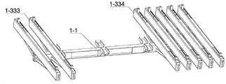
Referring to fig. 1-3, the vehicle body centering device of the three-dimensional parking equipment is arranged on a vehicle carrying board, and the vehicle carrying board is composed of a framework main beam 1-1, a vehicle passing platform 1-2 arranged on the framework main beam 1-1, and a plurality of supporting pieces 1-3 transversely arranged on the framework main beam 1-1 and used for supporting wheels; the framework main beam 1-1 is made of I-steel and has good bending resistance, and an oblique supporting beam 1-4 in rigid connection is arranged between the framework main beam 1-1 and the supporting piece 1-3 and is used for carrying out auxiliary support on the supporting piece 1-3 so as to ensure the stability of the automobile parking framework; the automobile passing platform 1-2 is simple in structure and good in bending resistance, and meets the automobile carrying function; the supporting piece 1-3 is composed of a rectangular pipe, and the end part of the rectangular pipe is provided with a sealing guide end cover 1-31; the rectangular pipes are arranged at intervals according to automobile tires and are connected with the framework main beam 1-1 by a special connecting plate.
Referring to fig. 5 to 9, the vehicle body centering device of the three-dimensional parking apparatus comprises two positive clamping members 3 arranged on each support member 1-3 and a positive clamping member driving mechanism for driving the two positive clamping members 3 to synchronously move towards or reversely move along the length direction of the support member 1-3, wherein the two positive clamping members 3 are symmetrically arranged at two ends of the support member 1-3, and each positive clamping member 3 comprises a connecting part 3-1 and a wheel pushing part 3-2 for pushing a wheel to perform a transverse movement; the positive clamping part driving mechanism comprises a motor 4-1 and a power transmission mechanism, wherein the power transmission mechanism is connected with a connecting part 3-1 of the positive clamping part 3.
Referring to fig. 3 and 4, openings 1-32 for accommodating clamping pieces 3 are respectively arranged on the top surfaces of two ends of the rectangular pipe supporting pieces 1-3, wheel pushing parts 3-2 of the clamping pieces 3 are positioned above the openings 1-32 of the supporting pieces 1-3, and connecting parts 3-1 of the clamping pieces 3 are arranged in the openings 1-32; the positive clamping part driving mechanism is arranged in the rectangular tube corresponding to the positive clamping part 3. The openings 1-32 can guide the clamping piece 3 in motion and play a role in limiting the stroke; simultaneously, will press from both sides positive actuating mechanism and set up in the rectangular pipe, can enough make full use of current space, can play the guard action to pressing from both sides positive actuating mechanism simultaneously again.
Referring to fig. 5-9, the clamping member driving mechanism comprises two sets of motors 4-1 and power transmission mechanisms, the two sets of motors 4-1 and power transmission mechanisms are symmetrically arranged about the transverse center plane of the supporting member 1-3, wherein the motor 4-1 is arranged in the middle of the supporting member 1-3. When the clamp is in work, the two groups of motors 4-1 respectively drive the two groups of power transmission mechanisms to act simultaneously, and further drive the clamp positive piece 3 to move close to or away from each other. The clamping piece 3 can obtain larger driving force by arranging two groups of motors 4-1 and a transmission mechanism; in addition, since the range of movement of the jaw positive member 3 is both ends of the supporting member 1-3, the motor 4-1 is disposed at the center of the supporting member 1-3 to make reasonable use of space.
Referring to fig. 5-9, the power transmission mechanism is composed of a ball screw 4-21 pair, wherein a screw 4-21 in the ball screw 4-21 pair is connected with an output shaft of a motor 4-1 through a reducer, a screw nut 4-22 in the ball screw 4-21 pair is connected with a connecting part 3-1 of a clamping part 3 through a connecting part 5, the external dimension of the motor 4-1 is smaller than the internal dimension of a rectangular pipe of the automobile parking framework, and the external dimension of the reducer is similar to the internal dimension of the rectangular pipe and is loosely matched with the internal dimension of the rectangular pipe. When the clamping device works, the output shaft of the motor 4-1 drives the screw rod 4-21 to rotate, and further drives the screw rod nut 4-22, the connecting piece 5 and the clamping piece 3 to do linear motion. The purpose of the arrangement is that the power transmission mechanism composed of the motor 4-1 and the ball screw 4-21 pair has the advantages of smooth operation, high transmission and positioning accuracy and the like, wherein the screw 4-21 in the ball screw 4-21 pair is a stepped integral shaft, the screw 4-21 close to one end of the motor 4-1 is a polished rod part, the screw 4-21 far away from one end of the motor 4-1 is a screw rod part with threads, and the length of the single-side threads of the screw 4-21 part is greater than the stroke length of the clamping piece 3. The advantage of this arrangement is that the tooling costs can be reduced while still providing the polished rod section with greater load carrying and torsion resistance.
Referring to fig. 4 and 9, the opening 1-32 has a proximal end 1-321 and a distal end 1-322, wherein the proximal end 1-321 is closer to the support member 1-3 than the distal end 1-322; the positive clamping part 3 is rotatably connected with the connecting piece 5, and a reset torsion spring 6 for promoting the positive clamping part 3 to rotate towards one side close to the proximal end part 1-321 is arranged between the positive clamping part 3 and the connecting piece 5. Through the arrangement, during work, after the centering task of the vehicle body is completed by the clamping piece 3, the clamping piece can be stored in the inner cavity of the supporting piece 1-3, so that interference on further vehicle transverse movement is avoided. Specifically, the storing operation is as follows: in the process of moving towards the end of the supporting part 1-3, the clamping positive part 3 is firstly contacted with the proximal end part 1-321 of the opening 1-32, after the contact, the connecting part 3-1 of the clamping positive part 3 continues to move towards the end, the wheel pushing part 3-2 rotates around a rotating shaft which is rotatably connected with the connecting part 5 under the action of the blocking of the proximal end part 1-321 of the opening 1-32, and when the clamping positive part 3 rotates 90 degrees, the clamping positive part 3 completely falls into the inner cavity of the supporting part 1-3. When the centering task needs to be performed on the clamping piece 3, the action of restoring the clamping piece 3 to the vertical state is as follows: under the action of the positive clamping piece driving mechanism, the positive clamping piece 3 moves towards the middle of the supporting pieces 1-3, and in the moving process, the elastic force of the reset torsion spring 6 prompts the positive clamping piece 3 to return to the vertical state.
Referring to fig. 10-15, the connecting member 5 includes a screw nut fixing portion 5-1 and a clamping member connecting portion 5-2, the clamping member connecting portion 5-2 includes two inner clamping plates, a fixing shaft is disposed between the two inner clamping plates, and the clamping member 3 and the reset torsion spring 6 are rotatably connected to the fixing shaft. The front clamping piece 3 is composed of I-shaped steel, a wedge-shaped block is welded on the back side of the front clamping piece 3, the reset torsion spring 6 is arranged in grooves on two sides of the I-shaped steel, and a central hole of the reset torsion spring 6 and a central hole of the front clamping piece 3 are located on the same central line 1-5. The advantage is located like this to set up, and the hardness of I-steel is high, and sets up the torsional spring in the recess of I-steel, can utilize the space effectively.
Referring to fig. 10-15, the clamping member connecting portion 5-2 further includes a limiting block 5-3 fixedly connected to the two inner clamping plates, and the limiting block 5-3 has a rotation limiting portion for limiting the clamping member 3 in rotation and a displacement limiting portion for limiting the horizontal end of the clamping member 3. The connecting piece 5 is provided with an upper guide supporting wheel 7-1 and a lower support guiding wheel 7-2 which are used for guiding and supporting the clamping piece 3 in motion, wherein the upper guide supporting wheel 7-1 is attached to the top surface of the inner wall of the supporting piece 1-3, and the lower guide supporting wheel is attached to the bottom surface of the inner wall of the supporting piece 1-3. The purpose of this setting is that when the positive clamping part 3 exerts thrust on the wheel, it will receive the reaction force of the wheel, the vertical component of the reaction force acts on the lead screw 4-21, which will affect the transmission precision and the service life of the lead screw 4-21, and through the above-mentioned guide supporting wheel, the positive clamping part 3 can be supported during the wheel pushing process, thereby avoiding the influence on the ball screw 4-21 pair, and at the same time, the guide supporting part 1-3 also plays a guiding role during the movement process.
Referring to fig. 10-15, two outer side clamping plates 8 are welded on the outer sides of the two inner side clamping plates, 3 guide supporting part holes are formed in two ends of each outer side clamping plate 8, an upper guide supporting wheel 7-1 and two upper guide supporting wheels 7-1 are respectively arranged on the three guide supporting holes, bearings are installed inside the guide supporting wheels, the distance between the outer surfaces of the outer side clamping plates 8 and the inner side surfaces of the rectangular pipe supporting pieces 1-3 are in loose fit, the length direction (without inverted arc edges) of the guide supporting wheels is larger than the width dimension of the rectangular holes formed in the upper surfaces of the rectangular pipes, and the upper guide supporting wheels 7-1 are limited inside the rectangular pipes.
The working principle of the invention is as follows:
when in work, if the central line 1-5 of the two front wheels or the two rear wheels is positioned at the left side of the central line 1-5 of the vehicle carrying plate, namely, when the two wheels are deviated to the left, the centering devices positioned at the outer sides of the two wheels synchronously move close to each other under the driving of the clamping piece driving mechanism (because the two clamping pieces 3 positioned on the supporting pieces 1-3 at the beginning of the movement are symmetrically arranged relative to the center line of the vehicle carrying plate and synchronously move at the same time, the two clamping pieces 3 are kept in a symmetrical state relative to the center line of the vehicle carrying plate at all times), in the process of movement, the wheel pushing part 3-2 of the left clamping piece 3 is firstly contacted with the left wheel, then, applying thrust to the left wheel to push the left wheel to move transversely rightwards, so that the central lines 1-5 of the two wheels are continuously close to the central line 1-5 of the vehicle carrying plate, and meanwhile, the right clamping piece 3 synchronously moves close to each other; when the right clamping piece 3 is contacted with the right wheel, the central lines 1-5 of the two wheels are superposed with the central line 1-5 of the vehicle carrying plate, the clamping piece driving mechanism stops acting, and the wheel clamp is opposite to the middle task to be completed;
the above is the working principle of the two clamping positive pieces 3, and specifically, in actual work, the following deviation situations can occur on the vehicle body:
1) when the front wheels and the rear wheels are deviated in a consistent direction, namely are deviated to the left side or are deviated to the right side simultaneously, for example, when the front wheels and the rear wheels are deviated to the left side simultaneously, the left clamping front parts 3 corresponding to the front wheels and the rear wheels are firstly contacted with the front wheels and the rear wheels on the left side respectively, and then the front wheels and the rear wheels are pushed to move towards the center line direction until the right clamping front parts 3 are firstly contacted with the front wheels and the rear wheels on the left side respectively, so that the task of clamping the whole vehicle body to be aligned to the center line; the same applies when the front wheel and the rear wheel deviate to the right side at the same time.
2) When the deviation of the front wheels is inconsistent with that of the rear wheels, for example, the two front wheels deviate to the left side, and the two rear wheels deviate to the right side, the left clamping front piece 3 corresponding to the front wheels contacts with the front wheels on the left side first, then the two front wheels are pushed to move towards the center line direction, the right clamping front piece 3 corresponding to the rear wheels contacts with the front wheels on the right side first, then the two rear wheels are pushed to move towards the center line direction until the right clamping front piece 3 contacts with the front wheels on the right side and the clamping front piece 3 on the left side contacts with the rear wheels on the left side, so that the task of clamping the whole vehicle body to be aligned to the center is; the same applies when the two front wheels deviate to the right and the two rear wheels deviate to the left.
Example 2
The present embodiment is different from embodiment 1 in that the motor 4-1 is a dual-shaft motor 4-1 (here, the dual-shaft motor refers to a motor having a rotating shaft, and two ends of the rotating shaft extend out of a motor body to form two output ends), the dual-shaft motor 4-1 is disposed in the middle of the supporting member 1-3, and the two sets of power transmission mechanisms are respectively connected to the output shafts at two ends of the dual-shaft motor 4-1. When the double-shaft motor synchronous transmission device works, the double-shaft motor 4-1 rotates to drive the two groups of power transmission mechanisms to act simultaneously, and the double-shaft motor synchronous transmission device has the advantages that the double-shaft motor 4-1 can synchronously output torque at the same time, has good synchronism, and can meet the requirement of synchronous movement of the two clamping pieces 3 at the same time.
Other embodiments other than the above-described embodiment are the same as embodiment 1.
Example 3:
the difference between this embodiment and embodiment 1 is that the power transmission mechanism is composed of a synchronous belt conveying mechanism, the connecting piece 5 is connected with a pushing block on the synchronous belt conveying mechanism, and during operation, the synchronous wheel rotates to drive the pushing block, the connecting piece 5 and the positive clamping piece 3 to move together.
Other embodiments other than the above-described embodiment are the same as embodiment 1.
The present invention is not limited to the above embodiments, and any other changes, modifications, substitutions, combinations, and simplifications which do not depart from the spirit and principle of the present invention should be construed as equivalents and are included in the scope of the present invention.