CN107708516B - Surface treatment apparatus and method - Google Patents
Surface treatment apparatus and method Download PDFInfo
- Publication number
- CN107708516B CN107708516B CN201680030827.4A CN201680030827A CN107708516B CN 107708516 B CN107708516 B CN 107708516B CN 201680030827 A CN201680030827 A CN 201680030827A CN 107708516 B CN107708516 B CN 107708516B
- Authority
- CN
- China
- Prior art keywords
- steam
- wiping head
- connector
- head
- connector assembly
- Prior art date
- Legal status (The legal status is an assumption and is not a legal conclusion. Google has not performed a legal analysis and makes no representation as to the accuracy of the status listed.)
- Active
Links
Images


Classifications
-
- A—HUMAN NECESSITIES
- A47—FURNITURE; DOMESTIC ARTICLES OR APPLIANCES; COFFEE MILLS; SPICE MILLS; SUCTION CLEANERS IN GENERAL
- A47L—DOMESTIC WASHING OR CLEANING; SUCTION CLEANERS IN GENERAL
- A47L13/00—Implements for cleaning floors, carpets, furniture, walls, or wall coverings
- A47L13/10—Scrubbing; Scouring; Cleaning; Polishing
- A47L13/20—Mops
- A47L13/22—Mops with liquid-feeding devices
- A47L13/225—Steam mops
-
- A—HUMAN NECESSITIES
- A47—FURNITURE; DOMESTIC ARTICLES OR APPLIANCES; COFFEE MILLS; SPICE MILLS; SUCTION CLEANERS IN GENERAL
- A47L—DOMESTIC WASHING OR CLEANING; SUCTION CLEANERS IN GENERAL
- A47L13/00—Implements for cleaning floors, carpets, furniture, walls, or wall coverings
- A47L13/10—Scrubbing; Scouring; Cleaning; Polishing
- A47L13/20—Mops
- A47L13/22—Mops with liquid-feeding devices
-
- A—HUMAN NECESSITIES
- A47—FURNITURE; DOMESTIC ARTICLES OR APPLIANCES; COFFEE MILLS; SPICE MILLS; SUCTION CLEANERS IN GENERAL
- A47L—DOMESTIC WASHING OR CLEANING; SUCTION CLEANERS IN GENERAL
- A47L13/00—Implements for cleaning floors, carpets, furniture, walls, or wall coverings
- A47L13/10—Scrubbing; Scouring; Cleaning; Polishing
- A47L13/20—Mops
- A47L13/24—Frames for mops; Mop heads
- A47L13/254—Plate frames
- A47L13/258—Plate frames of adjustable or foldable type
Landscapes
- Cleaning Implements For Floors, Carpets, Furniture, Walls, And The Like (AREA)
- Cleaning By Liquid Or Steam (AREA)
- Cleaning In General (AREA)
- Treatments Of Macromolecular Shaped Articles (AREA)
- Crushing And Grinding (AREA)
Abstract
Methods and apparatus for surface treatment may include a body, a connector assembly, and a wiping head configured for use in a non-steam and/or steam operation. The connector assembly may be configured to include a universal joint to receive different bodies or different wiping heads. The wiping head may be configured to rotate about a transverse axis relative to the connector assembly. One or both surfaces of the wiping head may be used for cleaning and a diverter valve mechanism may direct the flow of steam from one surface of the wiping head to the other. The apparatus may be configured for general area cleaning in a general area cleaning mode, or for cleaning hard and messy soils in a steam blast mode with or without a scrubbing action. In one embodiment, the apparatus may be configured to include a wiping head that includes a releasable flap.
Description
Cross reference to related patent applications
The present disclosure claims priority from united states provisional patent application entitled "surface treatment apparatus with steam reformer" and application number 62245195, filed 10/22/2015 and priority from united states provisional patent application entitled "surface treatment apparatus with releasable flaps" and application number 62166636, filed 5/26/2015, which are incorporated herein by reference.
Technical Field
The present disclosure relates to a surface treatment apparatus and method.
Background
Surface treating appliances are used in homes, offices, and other locations to treat floors and other surfaces. Various types of surface treating appliances, such as appliances having vibrating and/or rotating brushes, are known for cleaning carpets. In addition, certain types of bowel treating appliances, such as steamless wipers, spray appliances with pad constructions, or steam wipers with steam cleaning heads, may be used to clean and treat floors.
Disclosure of Invention
Methods and apparatus for surface treatment according to aspects of the present invention may be used for a variety of functions, such as no steam or steam cleaning or treatment, no steam or steam cleaning and treatment, and may include a body, a wiping head, and a connector assembly connecting the body and the wiping head, wherein the wiping head may be configured to rotate about a transverse axis of rotation relative to the connector assembly.
In aspects of the invention, methods and apparatus for surface treatment may include a connector assembly that may be configured to allow the body to be swapped with the body for various embodiments to allow for a variety of wiping head and body assemblies to allow for a variety of steam-free or steam cleaning and/or treatment operations.
In embodiments of the present disclosure, when used in a steam cleaning operation, a method and apparatus for surface treatment may include a steam source, a mop head connected to the steam source by a connector assembly. The connector assembly may be configured to include a universal joint or a combination of a universal joint and a connector housing, which may define a steam channel.
In one embodiment, the wiping head may include first and second opposing surfaces, wherein both the first and second opposing surfaces may be configured to output steam, or only either of the first or second opposing surfaces may be configured to output steam. In one embodiment, the wiping head may include a shifting device or mechanism to direct the flow of steam only to the first opposing surface when the second opposing surface faces upward, and to direct the flow of steam only to the second opposing surface when the first opposing surface faces upward.
In one embodiment, the connector assembly may include a connector steam inlet, a connector steam conduit, a steam blast nozzle assembly, and/or a mechanism that may allow steam to be output through the steam blast nozzle assembly (indicating a steam blast mode of operation) or through one of the first or second surfaces of the wiping head (indicating a general area cleaning mode of operation). The general area cleaning mode and the steam wind mode of operation may be determined by the position of the wiping head relative to the connector assembly, wherein the position of the wiping head may be determined by the angle between the wiping head and the connector assembly.
In one embodiment, the wiping head may be a reversible type of wiping head, wherein the wiping head may be rotated 180 ° from a first position to a second position, such that in the first position of the wiping head a first opposing surface of the wiping head may face upward and in the second position of the wiping head a second opposing surface of the wiping head may face upward.
In one embodiment, the wiping head may be rotated 180 ° from one position to another, such that in all positions of the wiping head, only the first or second opposing surfaces may face upward, but not both the first and second opposing surfaces. In such an embodiment, the steam wind mode of operation may be accompanied by a scrubbing action. The scrubbing action may be caused by providing a deployable scrubbing assembly that is engageable with an area to be cleaned when in a steam wind mode of operation and disengageable from the area when in a normal area cleaning mode of operation.
In one embodiment, a mop head of the present disclosure may include a frame, a tab releasably connected to a first side of the frame, and a joint pivotally connected to a second side of the frame, the first and second sides being opposite one another. The first side edge of each flap may be pivotally connected to the first side edge of the frame along spaced apart hinge axes. In one embodiment, the second side of each flap includes at least one projection configured to be received within a cavity defined in the inner surface of the pad. In one embodiment, each flap is configured to be removably attached to the inner surface of the pad.
In another embodiment, a mop head of the present disclosure may include a frame, a tab releasably connected to a first side of the frame, an attachment bar pivotally connected to a second side of the frame, first and second opposite sides, and a joint pivotally connected to the attachment bar. The first side edge of each flap may be pivotally connected to the first side edge of the frame along spaced apart hinge axes. In one embodiment, the second side of each flap includes at least one projection configured to be received within a cavity defined in the inner surface of the pad. In one embodiment, each flap is configured to be removably attached to the inner surface of the pad.
Drawings
1A-E are views of various exemplary components and their assemblies of an exemplary surface treatment apparatus according to the present disclosure;
2A-C are views and schematic diagrams illustrating an exemplary embodiment of a surface treatment apparatus for use in a steam cleaning operation including an exemplary embodiment of a changer device according to the present disclosure;
3A-D are views of an exemplary embodiment of a wiping head of a surface treating appliance for use in a steam cleaning operation, including another exemplary embodiment of a changer according to the present disclosure;
4A-C are views of an exemplary embodiment of a surface treating appliance for use in steam cleaning operations including a pivoting steam port according to the present disclosure;
fig. 5 is a view of an exemplary embodiment of a mop head including a steam port according to the present disclosure.
6A-D are views of various exemplary angular orientations of a wiping head relative to a connector assembly in an exemplary embodiment of a surface treating appliance according to the present disclosure;
fig. 7A-K are views of an exemplary embodiment of a surface treating appliance with or without a changer in the wiping head for use in a steam cleaning operation comprising a general area cleaning mode of operation and a steam wind mode of operation, wherein both the first and second opposing surfaces of the wiping head can be used for cleaning, according to the present disclosure.
Fig. 8A-P are views of an exemplary embodiment of a surface treatment device with or without a scrubbing function for use in a steam cleaning operation including a normal area cleaning mode of operation and a steam wind mode of operation, according to the present invention.
Fig. 9 is a view of an exemplary embodiment of a wiping head according to the present disclosure.
Fig. 10 is a view of an exemplary embodiment of a cleaning pad of the wiping head shown in fig. 9 according to the present disclosure.
11-11D are views of an exemplary embodiment of a tab of the wiping head shown in FIG. 9 for attachment and detachment of the cleaning pad shown in FIG. 10 according to the present disclosure.
12-12H are views and schematic diagrams illustrating an exemplary embodiment of a tab release mechanism of the mop head shown in FIG. 9 according to the present disclosure.
13-13E are views and schematic diagrams illustrating an exemplary embodiment of the tab release mechanism wiper head shown in FIG. 9 according to the present disclosure.
FIG. 14 is a view of the rotating yoke assembly of the wiping head shown in FIG. 9 according to the present disclosure.
15-15G are views and schematic diagrams illustrating one embodiment of a release mechanism.
FIG. 16 illustrates one embodiment of an apparatus including a coupling element and a vane ejector.
Fig. 16A is a schematic diagram illustrating one embodiment of a locking mechanism.
FIG. 17 shows a front view of a surface treatment system having (i) a steam application device equipped with a swivel to provide enhanced maneuverability and (ii) a portable steam source.
Detailed Description
It will be appreciated by those of ordinary skill in the art that the embodiments disclosed herein can be embodied in other specific forms without departing from the spirit or essential characteristics thereof. The presently disclosed embodiments are therefore considered in all respects to be illustrative and not restrictive.
Example embodiments will now be described hereinafter with reference to the accompanying drawings, which form a part hereof and show example embodiments which may be practiced. Such embodiments may be realized by any number of components configured to perform the specified functions and achieve the various results. For example, the present invention may employ various types of surface treatment devices that may perform various functions. Further, the invention may be practiced in conjunction with any number of cleaning or treatment processes. As used in this disclosure and the appended claims, the terms "embodiment," "example embodiment," and "exemplary embodiment" do not necessarily refer to a single embodiment, although they may refer to a single embodiment, and multiple example embodiments may be readily combined and interchanged without departing from the spirit or scope of the example embodiments. In addition, the terminology used herein is for the purpose of describing example embodiments only and is not intended to be limiting. In this regard, as used herein, the term "middle" may include "middle" and "upper," and the terms "a," "an," and "the" may include both singular and plural references. In addition, as used herein, the term "through" may also mean "by" depending on the context. Further, as used herein, the term "and/or" may mean and encompass any and all possible combinations of one or more of the associated listed items.
Various types of devices, such as a non-steam wiper or a steam wiper, may be used to clean and treat surfaces. Many non-steam wipers may include various combinations of handles, shafts, and cleaning heads. Many steam wipers can include various combinations of handles, shafts, water storage tanks, heating elements, and cleaning heads. A variety of cleaning pads are attachable to the cleaning head. The combination of the cleaning pad and cleaning head allows contact with the surface being cleaned or treated by the user.
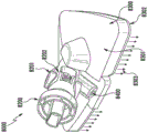
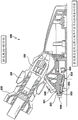
Fig. 1A-E illustrate an exemplary embodiment of a surface treatment system 1000 and its various components that may be used to steam-free or steam clean or treat a surface, such as a wooden or laminate floor. It should be appreciated that the surface treatment system 100 described herein may be used in a variety of operations to perform one or more cleaning or treatment functions. Surface treatment system 1000 may include a body 200, a connector assembly 300, and a scrub head 400 (FIG. 1A). As shown in fig. 1B-1E, the surface treatment system 100 can be assembled to include various combinations of the body 200, the connector assembly 300, and the mop head 400. The body 200 may include structural elements such as a shaft 210, a handle 220, and/or various combinations of a steam source 240 and/or a housing 230 that includes the steam source 240 (fig. 1B).
The connector assembly 300 may include a universal joint 310 (fig. 1C) that may be configured to be releasably and interchangeably connected to the various embodiments of the body 200 disclosed herein. The ability of the universal joint 310 to be releasably and interchangeably connected to multiple bodies 200 allows a wiping head 400 connected to the universal joint 310 to be releasably and interchangeably connected to multiple bodies 200 available in a surface treating system 100, resulting in multiple embodiments that can be assembled by the surface treating system 100 to form a surface treating device/apparatus. Additionally, multiple wiper heads 400 (FIG. 1D) of the same or different types may be configured to include the same universal joint 310 to allow for more combinations of different wiper heads 400 and different bodies 200 assembled from the surface treating system 100.
In one embodiment (fig. 1C), a first end of the universal joint 310 may be releasably and interchangeably connected to the body 200 and a second end of the universal joint 310 may be pivotally connected to the mop head 400. Universal joint 310 may be of any type configured to facilitate multiple combinations of multi-axis rotation (e.g., edge-to-edge, front-to-back, top-to-bottom, movement of wiper head 400 relative to body 200). In the embodiment shown in FIG. 1C, a first end portion of the universal joint 310 is connected to the body 200 and a second end portion of the universal joint 310 is connected to the mop head 400. The first end portion of the universal joint 310 may include an upper connector 320 and the second end portion may include a lower connector 330. The upper connector 320 may include a proximal end 321 for connecting to the body 200 and a distal end 322 for pivotally connecting to the proximal end 331 of the lower connector 330. The connection between the upper connector 320 and the lower connector 330 may allow for front-to-back and side-to-side movement of the body 200 relative to the connector assembly 330. The lower link 330 may further include a distal end 336 having a pair of side pivot arms 337, 338, the pair of side pivot arms 337, 338 extending laterally from the distal end 336. Side pivot arms 337, 338 are pivotally connected to the mop head 400.
As shown in fig. 1D, wiping head 400 may comprise any geometric shaped wiping head, such as wiping head 410 or wiping head 420. The wiping head 410 can include a front wall 411, a rear wall 412, a right side wall 413, and a left side wall 414 that define a frame. The wiping head 420 can include a right sidewall 421, a left sidewall 422, and a base 423 that define a frame. The frame of the wiping head 410 or the wiping head 420 may define a connector receiving opening 430 (e.g., fig. 1D (1)) in the rear wall 412 or a connector receiving opening 44 (e.g., fig. 1D (2)) in the base 423, respectively. Connector receiving opening 430 or 440 may be of any geometry. The mop head 410 may include connector receiving slot bushings 431, 432 within the connector receiving opening 430 for receiving the pivot arms 337, 338 of the lower link 33 of the universal joint 310, thereby allowing a pivotal connection between the universal joint 310 and the mop head 420. Additional structure (not shown) may be provided to secure the pivot arms 337, 338 in place. Similar to wiping head 410, wiping head 420 can include connector receiving slot bushings 441, 442 within connector receiving opening 440 for receiving pivot arms 337, 338 of lower link 330, thereby allowing a pivotal connection between universal joint 310 and wiping head 420. Additional structure (not shown) may be provided to secure the pivot arms 337, 338 in place. The pivotal connection between lower link 330 and wiping head 400 (e.g., wiping heads 410 and 420) allows for multi-axis pivoting, such as flipping, turning, or rotating, of wiping head 400 at a predetermined angle relative to connector assembly 300. Universal joint 310 of connector assembly 300 may also allow for ease of use, as it may facilitate easy attachment and detachment of wiping heads 410 and 420 (fig. 1D) from one or more bodies 200 (fig. 1B), while providing a universal pivoting and steering capability for the user. Additionally, the connector assembly 300 may also allow for cleaning or treatment using both the first and second opposing surfaces of the wiping heads 410, 420.
As shown in the embodiment of fig. 1E, the wiping head 420 may be oriented at an angle relative to the universal joint 310. The longitudinal and transverse axes 45, 46 may define a plurality of axes of rotation of the wiping head 420 relative to the universal joint 310. The wiping head 420 is rotatable about a transverse axis 460 relative to the longitudinal axis 450. The pivotal connection between the mop head 420 and the universal joint 310 may facilitate this movement. For example, the mop head 420 may be rotated 180 ° relative to the universal joint 310 to allow a user to clean or treat using both the first surface and the second surface of the mop head 420.
Embodiments of the surface treatment system 100 can be assembled into a steam wiper 1000 (fig. 2-8) for use in steam cleaning operations. The steam wiper may include devices similar to those described in commonly owned U.S. patent No.8,205,293, U.S. patent No.8,205,293 being incorporated by reference herein in its entirety for all purposes. In such embodiments, the body 200 may include a steam source 240, and steam from the steam source 240 may be directed to the mop head 400 through the connector assembly 300. In such embodiments, the connector assembly 300 may include a connector housing 380 (see fig. 1C) in addition to the universal joint 310. Connector housing 380 may provide a conduit to direct steam from steam source 240. In one embodiment, the connector housing may include a flexible steam hose (not shown) to direct steam from the steam source 240 to the mop head 400. The upper end of the steam hose may be connected to the steam source 240 and the lower end of the steam hose may be connected to the mop head 400.
As shown in fig. 2A, an exemplary embodiment of a steam wiper 1000 may be used to clean or treat a surface, such as a wooden or laminate floor. It should be appreciated that the steam wiper 1000 described herein may also be used as a treatment device that is treated or operated on a surface to perform one or more functions other than cleaning. As shown in fig. 2A, one embodiment of a vapor wiper 1000 can include a body 2000 (not shown), a wiping head 1040, and a connector assembly 1060. The connector assembly 1060 may include any rotational mechanism, such as a universal joint 1060, and the universal joint 1060 may include an upper component 1030 and a lower component 1020. The upper part 1030 of the universal joint 1060 is pivotally connected to the main body 2000 and the lower part 1020 of the universal joint 1060 is pivotally connected to the wiping shaft 1040. Universal joint 1060 may include any suitable connection mechanism to allow multiple degrees of freedom of movement between lower part 1020 of universal connector 1060 and wiping head 1040, and between upper part 1030 of universal connector 1060 and body 2000. The steam wiper may be provided with steam by a steam source, which may be an internal steam source 240 or an external steam source (not shown).
In one embodiment, the wiping head 1040 is configured to pivotally rotate relative to the connector assembly 1060 from a first position 1800, in which the second opposing surface 1140 of the wiping head can face upward (as shown in fig. 2B), to a second position 1850, in which the first opposing surface 1120 of the wiping head can face upward 1850. In one embodiment, the change in angle from the first position 1800 where the second opposing surface 1140 of the wiping head may face upward toward the wiping head 1040 to the second position 1850 where the first opposing surface 1120 of the wiping head may face upward toward the wiping head may be about 180, resulting in the wiping head 1040 being flipped over.
The wiping head 1040 can be configured to include a wiping head body 1080, which can include at least one wiping head steam inlet 1100 configured to receive steam and first and second opposing surfaces 1120, 1140 configured to output steam toward an area (not shown), such as a floor surface. As described above, steam may be generated by steam source 240 or a steam generator (not shown) coupled to steam wiper 1000 and supplied to wiping head steam inlet 1100. In an embodiment, steam may be provided from a steam generator (not shown) and supplied to the mop head steam inlet 1100 through a connector assembly 1060. In an embodiment, the wiping head 1040 can include additional wiping head steam inlets 1100. In an embodiment, the wiping head 1040 can further include a fluid conduit defined in the wiping head body 1080, the fluid conduit 1160 extending from at least one wiping head vapor inlet 1100 of the wiping head body 1080 to the first and second opposing surfaces 1120, 1140 of the wiping head body 1080, thereby defining at least first and second wiping head vapor paths 1180, 1200 leading to the first and second opposing surfaces 1120, 1140 of the wiping head body 1080, respectively.
A cleaning pad (not shown) can be attached to the wiping head 1040, overlying the first and second opposing surfaces 1120, 1140, and steam can be output from the first and second opposing surfaces 1120, 1140 through the cleaning pad to clean the surface. In one embodiment, steam may be output from both the first and second opposing surfaces 1120, 1140 simultaneously, whichever side is applied to the floor for cleaning. However, steam escaping from the side facing upwards will reduce the energy efficiency, resulting in a lower temperature of the steam being delivered to the side facing downwards.
In one embodiment, the transducer 1300 may be at least partially disposed in the fluid conduit 1160. The changer 1300 may be configured to move between a first changer position located in the first wiping head vapor path 1180 (as shown in fig. 2B) and a second changer position located in the second wiping head vapor path 1200 (as shown in fig. 2C). Referring to fig. 2B, when the wiping head 1040 is oriented in a second position 1800 in which a second opposing surface 1140 of the wiping head may face upward, the first opposing surface 1120 of the wiping head 1040 may face downward toward a cleaning area (not shown), such as a floor, and the changer 1300 may be located in the first changer position. The transducer 1300 may be configured to move to the second transducer position by any suitable means. For example, in one embodiment, the shifting apparatus 1300 may be configured to move to the second shifting apparatus position by gravity, manually applied force, mechanical force triggered by an activation device, or any other suitable means.
In the first changer position, the changer 1300 leaves the first wipe head vapor path 1180 unobstructed while blocking the second wipe head vapor path 1200. This will allow steam to be provided through the first wiping head steam path 1180 and output on the first opposing surface 1120 of the wiping head body 1080, but prevent steam in the fluid conduit 116 from being output on the second opposing surface 1140 of the wiping head body 1080.
Referring to fig. 2C, when the wiping head 1040 is oriented in a second position 1850 in which the first opposing surface 1120 of the wiping head may face upward, the second opposing surface 1140 of the wiping head 1040 may face downward toward a cleaning area (not shown), such as a floor, and the changer 1300 may be located in a second changer position. The transducer 1300 may be configured to move to the first transducer position by any suitable means. For example, in one embodiment, the shifting apparatus 1300 may be configured to move to the first apparatus position by gravity, manually applied force, or mechanical force triggered by an activation device.
In the second changer position, the changer 1300 will block the first wipe head vapor path 1180 while leaving the second wipe head vapor path 1200 unobstructed. This will allow steam to be provided through the second wiping head steam path 1200 and output on the second opposing surface 1200 of the wiping head body 1080, but prevent steam in the fluid conduit 1160 from being output on the first opposing surface 1120 of the wiping head body 1080.
With this configuration, the changer 1300 allows steam to be provided through the first opposing surface 1120 or the second opposing surface 1140, respectively, only when the wiping head 104 is oriented with the first opposing surface 1120 or the second opposing surface 1040 facing downward toward the cleaning area. At the same time, the changer 1300 prevents steam from being provided through the first opposing surface 1120 or the second opposing surface 1040 when the first opposing surface 1120 or the second opposing surface 1040 faces upward away from the cleaning area. This will improve cleaning performance and energy efficiency, as more heat is directed towards the cleaning surface and less heat is lost away from the cleaning surface.
In an embodiment, the wiping head 1040 can be configured to include first and second vapor chambers 1420, 1440 defined in first and second opposing surfaces 1120, 1140 of a wiping head body 1080. With this configuration, fluid conduit 1160 extends from the wiping head steam inlet 1100 of the wiping head body 1080 into the first and second steam chambers 1420, 1440, through which steam may be output from the first and second opposing surfaces 1120, 1140 as described. Specifically, the first wiping head vapor path 1180 may be at least partially defined by the fluid conduit 1160 and the first vapor chamber 1420, and the second wiping head vapor path 1200 may be at least partially defined by the fluid conduit 1160 and the second vapor chamber 1440. Depending on the orientation of the wiping head 1040, the changer 1300 may block one of the first and second wiping head vapor paths 1180, 1200 while leaving the other of the first and second wiping head vapor paths 1180, 1200 unobstructed as described above.
It should be appreciated that the transducer 1300 may be configured in a variety of ways in accordance with the principles disclosed herein. In one embodiment, as shown in fig. 2A-2C, the transducer 1300 can include a transducer body 1500 at least partially disposed in the fluid conduit 1160. The conversion device body 1500 can have first and second end portions 1520, 1540 and first and second shoulders 1560, 1580 extending outwardly from the first and second end portions 1520, 1540, respectively. The first shoulder 1560 and the changer body 1500 are configured to cooperate to block the second wiping head vapor path 1200 when the changer 1300 is in the first changer position, and the second shoulder 1580 and the changer body 1500 are configured to cooperate to block the first wiping head vapor path 1180 when the changer 1300 is in the second changer position.
In one embodiment, the first shoulder 1560 includes a sealing element 1600, such as an O-ring disposed on the shoulder surface 1620 facing the second shoulder 1580. The second shoulder 158 may also include a similar sealing element 1640 disposed on a shoulder surface 1660 facing the first shoulder 1560. In one embodiment, the shoulder surfaces 1620 and 1640 may be sloped to give the transducer body 1500 an hourglass shape and a trapezoidal cross-sectional profile, as shown in fig. 2B and 2C.
It should be appreciated that the wiping head 1040 can have a variety of configurations to accommodate the configuration of the changer 1300. In one embodiment, transducer 1300 may comprise a ball valve and wiping head 1040 may take the configuration of wiping head 2000 as shown in fig. 3A-3D.
Referring to fig. 3A-3D, wiping head 2040 may be similarly configured to wiping head 1040 except that the shifting apparatus may include a valve 2300 and fluid conduit 2160 may be differently configured from fluid conduit 1160 to define first and second wiping head vapor paths 2180, 2200 different from first and second wiping head vapor paths 1180, 1200. In one embodiment, the fluid conduit 2160 may extend along the first wiping head vapor path 2180 from the wiping head vapor inlet 2100, through a portion of the second opposing surface 2140 to the first opposing surface 2120, as shown in fig. 3C. Further, the conduit 2160 may extend from the mop head steam inlet 2100 along the second mop head steam path 2200, through a portion of the first opposing surface 2120 to the second opposing surface 2140, as shown in fig. 3D. In one embodiment, the valve 2300 may include a sealing element 2340 disposed within a cavity 2320 defined in the fluid conduit 2160. In one embodiment, the valve 2300 may comprise a ball valve and the sealing element 2340 may comprise a substantially spherical configuration, such as a ball, and may be made of any suitable material, such as a metal, a polymer, teflon, or the like. The sealing element 2340 may be configured to move between a first valve position located in the second wiper head vapor path 2200 (as shown in fig. 3C) and a second valve position located in the first wiper head vapor path 2180 (as shown in fig. 3D).
Referring to fig. 3C, when the wiping head 2040 is oriented in the second position 2800 in which the second opposing surface 2140 of the wiping head may face upwardly, the first opposing surface 2120 of the wiping head 2040 may face downwardly toward a cleaning area (not shown), such as a floor, and the sealing element 2340 may be located in the first valve position in the second wiping head vapor path 2200, the sealing element 2340 will leave the first vapor path 2180 unobstructed while blocking the second vapor path 2200. This will allow steam to be provided through the first wiping head steam path 2180 and output on the first opposing surface 2120, but prevent steam in the fluid conduit 2160 from being output on the second opposing surface 2140.
Referring to fig. 3D, when the wiping head 2400 is oriented in the second position 2850 in which the first opposing surface 212 of the wiping head may face upward, the second opposing surface 2140 of the wiping head 2040 may face downward toward a cleaning surface (not shown), such as a floor, and the sealing element 2340 may be located in the second valve position in the first steam path 2180. In the second valve position, the sealing element 2340 will block the first wiping head vapor path 2180 while leaving the second wiping head vapor path 2200 unobstructed. This will allow steam to be provided through the second wiper head steam path 2200 and output on the second opposing surface 2200, but prevent steam in the fluid conduit 2160 from being output on the first opposing surface 2120.
Fig. 4A-4C illustrate another embodiment of a steam wiper 3000. The steam wiper 3000 may include a wiping head 3040 and a lower member 3020 of a universal joint 3060 having an end portion 3050 pivotally connected to the wiping head 3040. In an embodiment, the end portion 3050 can include a pivoting steam port 3080, and the pivoting steam port 3080 can be fluidly connected to the steam source 240 (not shown), such as a steam generator. The pivotal steam port 3080 may be part of the lower component 3020 of the universal joint 3060 and pivot about the same axis as the lower component 3020 of the universal joint 3060 and pivot in relation to the lower component 3020 of the universal joint 3060. In an embodiment, the pivoting steam port 3080 may include a single nozzle configured to provide steam from the steam source 240 to the wiping head 3040. In an embodiment, the pivoting steam ports 3080 may include a plurality of nozzles configured to provide steam from the steam source 240 to the wiping head 3040.
In one embodiment, the wiping head 304 may include a first vapor chamber 3420, which may include first vapor chamber inlets 3460 and may be configured to output vapor on the first opposing surface 3120 of the wiping head 3040. The wiping head 3040 may further include a second vapor chamber 3440, which may include second vapor chamber inlets 3480 and may be configured to output vapor on a second opposing surface 3140 of the wiping head 3040.
Similar to the wiping heads 1040 and 2000, the wiping head 3040 can be configured to pivotally rotate relative to the connector assembly from the second position to the first position. When the wiping head 3040 is oriented in a second position in which the second opposing surface 3140 of the wiping head faces upward, the first steam chamber portals 3460 may be configured to align with the pivoting steam ports 3080 of the lower component 3020 of the universal joint 3060, allowing steam to be provided to the first steam chambers 3420 and output on the first opposing surface 3120 of the wiping head 3040. When the wiping head 3040 is oriented in a second position in which the first opposing surface 3120 of the wiping head faces upwardly, the second vapor chamber portals 3480 are configured to align with the pivoting vapor ports 3080 of the lower component 3020 of the universal joint 3060, allowing vapor to be provided to the second vapor chambers 3440 and output on the second opposing surface 3140 of the wiping head 3040.
It will be appreciated that the alignment of the pivoting steam vents 3080 with the first or second steam chamber inlets 3460, 3480 allows steam to be provided only to the steam chamber outputting steam towards the cleaning surface (not shown), which in turn allows for improved energy efficiency and cleaning performance as described above for the wiping heads 1040 and 2040.
It should further be appreciated that the steam wiping heads 1040, 2040, and 3040 may be configured to include at least one steam port 4000 as shown in fig. 5 to allow residual and/or excess steam to escape from the downward facing steam chamber 4020 to the upward facing steam chamber 4040. In one embodiment, the steam vents 4000 can include one or more apertures defined through a portion of the wiping head 4040 to fluidly connect the steam chambers 4020 and 4040. In one embodiment, a fluid regulating device, such as a shut-off valve (not shown), can open or block the passage of fluid through the steam port 4000 automatically or upon activation by a user.
In one embodiment of the surface treating apparatus 100 shown in fig. 1A-E, when the apparatus is used for a steam cleaning operation, the connector housing 380 may include a connector steam inlet, a connector steam conduit (as shown in fig. 7 and 8) including first and second connector steam paths (as shown in fig. 7 and 8), and a steam wind nozzle assembly (as shown in fig. 7 and 8) in fluid communication with one of the first and second connector steam paths (as shown in fig. 7 and 8). Fig. 6A-D present an exemplary embodiment of a surface vapor wiper 100 with a wiping head 400 having different angular orientations relative to the connector assembly 300. The wiping head 400 in each of the illustrated embodiments has two opposing surfaces, a first opposing surface 510 and a second opposing surface 520.
In the exemplary embodiment of the wiping head in fig. 6A and 6B, the wiping head 400 can be configured to be oriented in a first position 600 relative to the connector assembly 300, and in the exemplary embodiment of the wiping head in fig. 6C and 6D, the wiping head 400 can be configured to be oriented in a second position 700 relative to the connector assembly 300. When the mop head is in the first position 600, as shown in fig. 6A, the first opposing surface 510 of the mop head 400 may be oriented upward and at a first predetermined angle 530 with respect to the connector assembly 300; and as shown in fig. 6B, the second opposing surface 520 of the mop head 400 may be oriented upward and at a first predetermined angle 530 with respect to the connector assembly 300. When the mop head is in the second position 700, as shown in fig. 6C, the first opposing surface 510 of the mop head 400 may be oriented upward and at a second predetermined angle 540 relative to the connector assembly 300; and as shown in fig. 6D, the second opposing surface 520 of the scrub head 400 can be oriented upward and at a second predetermined angle 540 relative to the connector assembly 300.
In the embodiment in fig. 6C and 6D, steam may be directed from the connector housing 380 (shown in fig. 7 and 8) to the mop head 400 along one of the first and second connector steam paths (shown in fig. 7 and 8) for output in the general area cleaning mode 700. In the embodiment in fig. 6A and 6B, steam may be directed from the connector housing 380 to a steam wind nozzle assembly (as shown in fig. 7 and 8) along the other of the first and second connector steam paths for output in a steam wind pattern 600. The steam wind mode of operation 600 or the general area cleaning mode of operation 700 may be initiated depending on the first or second predetermined angle 530 and 540 of the mop head 400 relative to the connector assembly 300. As shown in fig. 6A and 6B, the wiping head 400 may be oriented at a first predetermined angle 530 relative to the connector assembly 300, allowing a steam wind mode 600 of operation, and in fig. 6C and 6D, the wiping head 400 may be oriented at a second predetermined angle 540 relative to the connector assembly 300, allowing a general area cleaning mode 700 of operation. The first predetermined angle 530 relative to the wiping head can be an acute angle (e.g., fig. 6A and 6B) and the second predetermined angle 540 relative to the wiping head can be an obtuse angle (e.g., fig. 6C and 6D).
It may be noted that the coverage area in the normal area cleaning mode 700 of operation may be larger than the coverage area in the steam wind mode 600 of operation, and the speed of the steam output in the steam wind mode 600 of operation may be higher than the speed of the steam output in the normal area cleaning mode 700 of operation. The steam wind mode of operation 600 is effective and efficient in cleaning or treating difficult to remove or messy soils. It may also be noted that the steam wind in the steam wind mode of operation relies on velocity and hydration to break up the dirt that is difficult to remove. For example, if the hard-to-remove soil considered is a layer that accumulates, as steam begins to hydrate the top layer soil, the top layer soil is displaced due to the velocity of the outgoing steam, exposing the next layer of soil to be hydrated.
Fig. 7A-7K depict views of an exemplary embodiment of a steam wiper 7000 that may be configured to discharge steam in a general area cleaning mode and a steam wind mode depending on the angle of wiping head 7300 relative to connector assembly 7200. In one embodiment, steam wiper 7000 may include a wiping head 7300, a variation of which is constructed in accordance with the principles disclosed herein, including but not limited to any of the embodiments described in fig. 2A-2C or fig. 3A-3D or fig. 4A-4C.
In fig. 7A-7F, an exemplary embodiment of a steam wiper 7000 may include a connector assembly 7200 (embodiment of connector assembly 300 of fig. 1A, 1C) and a wiping head 7300 (embodiment of wiping head 400 of fig. 1A, 1D). Connector assembly 7200 can include universal joint 7201, universal joint 7201 can be configured to connect to a wiping head 7300 and a connector housing 7202 (an embodiment of connector housing 380 of fig. 1C), which can include a connector steam inlet 7302, a connector steam conduit 7204, and a steam air nozzle assembly 7400. Connector steam inlet 7302, connector steam conduit 7204, steam air nozzle assembly 7400 may be fluidly connected to each other. Connector steam inlet 7302 may be fluidly connected to steam source 240, receiving steam from steam source 240 and directing the received steam to connector steam conduit 7204. Connector steam conduit 7204 may include first connector steam path 7205 and second connector steam path 7206, allowing steam to be selectively directed through first connector steam path 7205 to steam wind nozzle assembly 7400, or through second connector steam path 7206 to wiping head 7300. The wiping head 7300 may include a first opposing surface 7301 and a second opposing surface 7302.
As shown in fig. 7A, wiping head 7300 is at a second predetermined angle (see fig. 6C and 6D) relative to connector assembly 7200, thereby defining a second position of wiping head 7300 relative to connector assembly 7200, and in such an embodiment, steam can be directed through second connector steam path 7206 to wiping head 7300, thereby initiating a normal zone cleaning mode of operation. As shown in fig. 7B, wiping head 7300 is at a first predetermined angle (see fig. 6A and 6B) relative to connector assembly 7200, thereby defining a first position of wiping head 7300 relative to connector assembly 7200, and in such an embodiment, steam may be directed through first connector steam path 7205 to steam wind nozzle assembly 7400, thereby initiating steam wind mode 7401 of operation.
Referring to fig. 7C, a partial cross-sectional view of the exemplary embodiment of fig. 7A is shown with a longitudinal cross-sectional view of the wiping head 7300. Referring to fig. 7D, a longitudinal cross-sectional view of both wiping head 7300 and connector assembly 7200 of the exemplary embodiment depicted in fig. 7A is shown. As shown in the embodiment of fig. 7D, steam air nozzle assembly 7400 may include three portions: a nozzle inlet section 7402, a nozzle intermediate section 7403, and a nozzle outlet section 7404. In one embodiment, the cross-sectional surface area of the nozzle inlet portion 7402 or the nozzle intermediate portion 7403 may be less than the cross-sectional surface area of the nozzle outlet portion 7404. In one embodiment, the cross-sectional surface area of the nozzle intermediate portion 7403 may be less than the cross-sectional surface area of the nozzle inlet portion 7402 and the nozzle outlet portion 7404.
In one embodiment, the nozzle inlet, intermediate and outlet portions 7402, 7403, 7404 may be of any geometric shape, such as cylindrical, cubic, hexahedral, etc., wherein the nozzle inlet, intermediate and outlet portions 7402, 7403, 7404 may be of the same geometric shape or of different geometric shapes from one another. In one embodiment, the nozzle outlet portion 7404 may be substantially conical, as shown in fig. 7D. The shape and/or size and/or angular orientation of the nozzle inlet portion, nozzle intermediate portion, nozzle outlet portion 7402, 7403, 7404 of steam wind nozzle assembly 7400 may determine the velocity and profile of the steam wind. For example, the velocity of steam blown out of the steam blast nozzle assembly 7400 may be defined by the narrow cross-sectional surface area of the nozzle intermediate portion 7403 relative to the nozzle inlet and outlet portions 7402 and 7404. A narrow nozzle mid-portion 7303 may confine the higher velocity steam wind. Furthermore, the narrow cross-sectional surface area of the nozzle intermediate portion 7403 relative to the nozzle inlet and outlet portions 7402 and 7404 also determines the sound (audible jet) of the steam wind. In one embodiment, the shape of the nozzle outlet portion 7404 may define a steam wind profile.
As shown in fig. 7D, the wiping head 7300 may include a wiping head vapor inlet 7304 to receive vapor into the wiping head 7300, allowing the vapor to be output through the first and/or second opposing surfaces 7301, 7302 of the wiping head 7300. It may be noted that wiping head steam inlets 7304 may include one or more wiping head steam inlets 7304. Fig. 7E is a longitudinal cross-sectional view showing the connector assembly 7200 and wiping head 7300 of the embodiment shown in fig. 7B depicting a steam wind mode of operation 7401. The steam exiting the nozzle outlet portion 7404 of the steam wind nozzle assembly 7400 may appear as a steam wind or steam jet 7405. Solid line 7407 represents the flow of steam through connector steam inlet 7302 and first connector steam path 7205 of connector steam conduit 7204 to steam wind nozzle assembly 7400 and ultimately to the exterior as steam wind through steam wind nozzle assembly 7400.
Fig. 7F is a longitudinal cross-sectional view showing the connector assembly 7200 and wiping head 7300 of the embodiment shown in fig. 7A depicting a general area cleaning mode of operation 7303. A solid line 7305 shows a steam flow that passes through the connector steam inlet 7203 and the second connector steam path 7206 of the connector steam conduit 7204 to the wiper head steam inlet 7304, which steam flow may be output through the first or second opposing surfaces 7301, 7302 of the wiper head 7300, allowing the steam to be used for general area cleaning.
In one embodiment, connector housing 7202 may further comprise a valve mechanism 7700 configured to switchably direct steam flow through first connector steam path 7205 to steam wind nozzle assembly 7400 (fig. 7H), or through second connector steam path 7206 to wiper head steam inlet 7304 (fig. 7G). In an embodiment, the valve mechanism 7700 can be disposed in at least a portion of the first connector vapor path 7205 or at least a portion of the second connector vapor path 7206, or in both at least a portion of the first connector vapor path 7205 and at least a portion of the second connector vapor path 7206. The valve mechanism 7700 can be configured to include a first baffle 7710 and a second baffle 7720 that cooperate to form at least a portion of the first connector steam path 7205 or at least a portion of the second connector steam path 7206 depending on the relative positions of the first and second baffles 7710 and 7720.
The first and second shutters 7710 and 7720 have a first relative position 7730 (e.g., fig. 7H) when the wiping head 7300 is oriented at a first predetermined angle 530 with respect to the connector assembly 7200 and a second relative position 7740 (e.g., fig. 7G) when the wiping head 7300 is oriented at a second predetermined angle 540 with respect to the connector assembly 7200. In a first relative position of the first and second shutters 7710 and 7720, the second connector vapor path 7206 may be blocked (e.g., fig. 7H), and in a second relative position of the first and second shutters 7710 and 7720, the first connector vapor path 7205 may be blocked (e.g., fig. 7G). As can be shown in fig. 7G and 7H, the first barrier 771 may include a first spring member 7711, a first barrier member 7712, a first seal member 7713, and a second seal member 7714 such that the first barrier member 7712 is biased by the first spring member 7711 in the open position. The sealing element may comprise any sealing mechanism, such as an O-ring. The first spring member 7711 may have first and second ends, and the first shutter member 7712 may have first and second ends.
The first baffle member 7712 may have an elongated groove 7715. The first seal member 7713 may be located near a first end of the first barrier member 7712 and the second seal member 7714 may be located near a second end of the first barrier member 7712. It may be noted that the position of the sealing members 7713, 7714 on the first baffle member 7712 may vary in some embodiments. In a first relative position (e.g., fig. 7H), the first end of the first flap member 7712 may be located on the second end of the first spring member 7711, and in a second relative position (e.g., fig. 7G), the first end of the first flap member 7712 may be moved proximally toward the first end of the first spring member 7711.
Similarly, the second flapper 772 includes a second spring member 7721, a second flapper member 7722, a third sealing element 7723, and a fourth sealing element 7724. The second flap member 7722 may be biased in the open position by a second spring member 7721. The second spring member 7721 may have first and second ends, and the second baffle member 7722 may also have first and second ends. The third sealing element 7723 may be located near a first end of the second baffle member 7722 and the fourth sealing element 7724 may be located near a second end of the second baffle member. The location or positioning of the sealing elements 7723, 7724 on the second baffle member 7722 may vary. A second end of the second baffle member 7722 may movably extend into the elongated recess 7715 of the first baffle member 7712 such that the second end of the second baffle member 7722 may abut a first end of the elongated recess 7715 of the first baffle member 7712 at a first relative position (e.g., fig. 7H) and the second end of the second baffle member 7722 may abut a second end of the elongated recess 7715 of the first baffle member 7712 at a second relative position (e.g., fig. 7G). Thus, in a first relative position (e.g., fig. 7H) the first end of the second baffle member 7722 moves proximally toward the first end of the second spring member 7721, and in a second relative position (e.g., fig. 7G) the first end of the second baffle member 7722 may be located on the second end of the second spring member 7721. In fig. 7G, the circular ring 7716 represents the steam wind path of the seal, and in fig. 7H, the circular ring represents the general area cleaning path of the seal.
In yet another exemplary embodiment of the steam wiper 7000 shown in fig. 7I-7K, the valve mechanisms described in fig. 7G and 7H may be configured to include different valve mechanisms. In the exemplary embodiment of the steam wiper 7000 shown in fig. 7I, the steam wiper 7000 can comprise a wiping head 7300, the transformation 1300 or 2300 or 3300 of which is as described in fig. 2A-2C or fig. 3A-3D or fig. 4A-4C. In such an embodiment shown in fig. 7I, the valve mechanism 7700 can include a single baffle 7740 that extends at least partially from the conversion device of the wiping head 7300 and is disposed at least partially in the first connector steam path 7205 and the second connector steam path 7206, thereby allowing for control of the direction of steam flow to the steam wind nozzle assembly 7400 or the wiping head 7300.
The single shield 7740 may include a shield spring member 7741, a shield member 7742, a first sealing element 7743, and a second sealing element 7744. In path 1 of fig. 7I, steam is directed to wiping head 7300, and in path 2 of fig. 7I, steam is directed to steam wind nozzle assembly 7400. In another embodiment of the steam wiper shown in fig. 7I, the valve mechanism 7700 can include first and second baffles such that the first baffle extends at least partially from a transducing device of the wiping head 7300 that is at least partially located in a first steam chamber of the wiping head 7300, and the second baffle extends at least partially from a transducing device of the wiping head 7300 that is at least partially located in a second steam chamber of the wiping head, thereby allowing control of the direction of steam flow to the steam wind nozzle assembly 7400 (path 2) or the wiping head 7300 (path 1).
Fig. 7J and 7K illustrate additional embodiments of a valve mechanism 7700. Valve mechanism 7750 in fig. 7J or valve mechanism 776 in fig. 7K will allow or block steam flow to either wiping head 7300 or to steam wind nozzle assembly 7400 by directing steam flow completely to either steam wind nozzle assembly 7400 (path 2) or wiping head 7300 (path 1), or by blocking steam flow to either steam wind nozzle assembly 7400 or wiping head 7300 depending on the first or second position of wiping head 7300 relative to connector assembly 7200 (see fig. 3A-6D). The valve mechanism 7750 may accordingly include a spring member 7751, a valve member 7752, and two sealing elements 7753 and 7754. Likewise, the valve mechanism 7760 may include a spring member 7761, a valve member 7762, and sealing members 7763 and 7764, respectively.
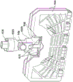
Fig. 8A-8K illustrate an exemplary embodiment of a steam wiper 8000 that can be configured to discharge steam in a general area cleaning mode and a steam wind mode, with or without a scrubbing action. In fig. 8A, an exemplary embodiment of a steam wiper 8000 is shown including a connector assembly 8200 (an embodiment of the connector assembly 300 of fig. 1A, 1C) and a wiping head 8300 (an embodiment of the wiping head 400 of fig. 1A, 1D). Connector assembly 8200 includes a universal joint 8201 configured to connect to a wiping head 8300 and a connector housing 8202 (an embodiment of connector housing 380 of fig. 1C), connector housing 8202 may include a connector steam inlet 8203, a connector steam conduit 8204, and a steam air nozzle assembly 8400.
The wiping head 8300 can include first and second opposing surfaces 8301, 8302 and a wiping head 8300 housing 8330 enclosed between the first and second opposing surfaces 8301, 8302. The wiping head 8300 housing 8330 can include one or more wiping head 8300 steam inlets 8304 to receive steam from the connector housing and one or more wiping head 8300 steam outlets 8305 fluidly connected to each other such that steam is directed from the wiping head 8300 steam inlets 8304 to the wiping head 8300 steam outlets 8305 for output over the cleaning area. In the wiping head 8300, there may be a fluid conduit (not shown) fluidly connecting the wiping head 8300 steam inlet 8304 to the wiping head 8300 steam outlet 8305. A wiping head 8300 steam inlet 8304 can be fluidly connected to the connector housing 8202. The wiping head 8300 can be made in any geometric shape, such as triangular (as shown in figure 8A), rectangular, or any shape, and can be made of any material.
In one embodiment, the first opposing surface 8301 is not configured to output steam. For example, the first opposing surface 8301 may include a rigid housing made of any material, such as plastic, metal, etc., and/or may be an enclosed structure. Thus, such a wiping head 8300 may not be reversible, such that the second opposing surface 8302 may face upward. In such a wiping head 8300, the first opposing surface is the only surface that always faces upward.
In one embodiment, the wiping head 8300 can include a base 8311, a right wall 8312, and a left wall 8313. The connector assembly 8200 may be pivotally connected to the base 8311. The second opposing surface 8302 may comprise a cleaning pad holding surface and be configured to output steam onto an area to be cleaned or treated. Cleaning pad 8309 can be removably attached to a cleaning pad retaining surface of second opposing surface 8302, allowing steam to be output through cleaning pad 8309 onto an area to be cleaned/treated. The wiping head 8300 can define a connector receiving portion 8340, which can have any shape and receive at least a portion of a connector housing. A universal joint 8201 may be pivotally connected to the connector receiving protrusions 8341 and 8342. The steam air nozzle assembly 8400 may extend at least partially into the connector assembly 8200, as shown in fig. 8A.
In one embodiment, as shown in fig. 8B, the wiping head 8300 is at a second predetermined angle a relative to the connector assembly 82002(substantially similar to the second predetermined angle depicted in fig. 6C) to define a second position of the wiping head 8300 relative to the connector assembly 8200. In such embodiments, steam may be directed through a second connector steam path 8206 (fig. 8D-8E) to the wiping head 8300, thereby defining a general area cleaning mode 8303 of operation.
As shown in fig. 8D-8E, a first connector vapor path 8205 can be fluidly connected to vapor wind nozzle assembly 8400 and a second connector vapor path 8206 can be connected to wiping head 8300. In the exemplary embodiment of the steam wiper 8000 as shown in FIG. 8C, the wiping head 8300 is at a first predetermined angle A relative to the connector assembly 82001(substantially similar to the first predetermined angle depicted in fig. 6A) to define a first position of the wiping head 8300 relative to the connector assembly. In such embodiments, steam may be directed through a first connector steam path 8205 (fig. 8D-8E) to the steam wind nozzle assembly 8400, defining a steam wind mode of operation 8401.
Referring to fig. 8D and 8E, longitudinal cross-sectional views of both the connector assembly 8200 and the wiping head 8300 of the exemplary embodiment depicted in fig. 8A can be shown. The steam air nozzle assembly 8400 may be configured in a variety of ways as described in fig. 7A-7K. Figure 8D is a longitudinal cross-sectional view of the connector assembly 8200 and wiping head 8300 showing a general area cleaning mode 8303 of operation. Solid line 8307 shows the flow of steam that reaches the wiping head 8300 steam inlet 8304 through the connector steam inlet 8203 and the second connector steam path 8206 of the connector steam conduit 8204, and can be output through the second opposing surface 8302 of the wiping head 8300, allowing steam to be used for general area cleaning.
Figure 8E is a longitudinal cross-sectional view of the connector assembly 8200 and wiping head 8300 showing a steam wind mode 8401 of operation. The steam exiting the nozzle outlet portion 8404 of the steam wind nozzle assembly 8400 may appear as a steam wind or steam jet. Solid line 8407 shows the flow of steam through connector steam inlet 8203 and first connector steam path 8205 of connector steam conduit 8204 to steam wind nozzle assembly 8400, and ultimately to the exterior through steam wind nozzle assembly 8400 as a stream of steam wind.
In the exemplary embodiment 800 of the steam wiper shown in fig. 8F and 8I, this embodiment may include a valve mechanism 8700 to direct the flow of steam to: a wipe head 8300, allowing a general area cleaning mode 8403 to operate (e.g., fig. 8H); or a steam wind nozzle assembly, allowing a steam wind mode of operation (e.g., fig. 8I). In the exemplified embodiment of fig. 8F and 8I, the connector housing 8202 can further comprise a valve mechanism 8700 configured to switchably direct a flow of steam through the first connector steam path 8205 to the steam air nozzle assembly 8400 (e.g., fig. 8I) or through the second connector steam path 8206 to the wiping head 8300 steam inlet 8304 (e.g., fig. 8H), wherein the valve mechanism 8700 can be disposed in at least a portion of the first connector steam path 8205 or at least a portion of the second connector steam path 8206, or both at least a portion of the first connector steam path 8205 and at least a portion of the second connector steam path 8206.
The valve mechanism 8700 can be the valve mechanism shown in fig. 7G and 7H or can be a shifting valve mechanism similar to the shifting apparatus shown in fig. 2A-2C or fig. 3A-3D or 4A-4C. Valve mechanism 8700 can include a variety of valve mechanisms. In one embodiment shown in fig. 8F, valve mechanism 8700 can be a shifting device 8800 can be disposed at least partially in first connector vapor path 8205 and second connector vapor path 8206. The conversion device 8800 can be configured to move between a first conversion device position located in the first connector vapor path 8205 and a second conversion device position located in the second connector vapor path 8206.
When the wiping head 8300 is oriented in the second position, the conversion device 8800 can be located in the second conversion device position. The conversion device 8800 can be configured to move between the first and second conversion device positions by any suitable means. For example, the shifting device 8800 can be configured to move to the first or second shifting device positions by gravity, manually applied force, mechanical force triggered by an activation device, or any other suitable means. In the second changer position, the changer 8800 will block the first connector vapor path 8205 while leaving the second connector vapor path 8206 unobstructed. This will allow steam to be provided to the wiping head 8300 through the second connector steam path 8206. When the wiping head 8300 is oriented in the first position, the conversion device 8800 can be located in the first conversion device position. In the first conversion device position, conversion device 8800 would leave first connector vapor path 8205 unobstructed and block second connector vapor path 8206. This will allow steam to be provided to the steam air nozzle assembly 8400 through the first connector steam path 8205, but prevent steam from entering the wiping head 8300.
In one embodiment shown in fig. 8F, the conversion device 8800 can include a valve body 8802, a valve spring member 8801, and a sealing element such as an O-ring 8803. The valve body 8802 can include a first end portion and a second end portion. Proximate the first end portion, the valve body 8802 can include first and second shoulders 8821, 8822 extending outwardly from the valve body 8802. The first and second shoulders 8821, 8822 may be perpendicular to the valve body. The O-ring 8803 is located at the intersection of the first shoulder 8821 and the first end facing portion of the valve body 8802. The location of O-ring 8803 may not be considered limiting. The conversion device 8800 can be contained in a valve packaging assembly 8701 that also contains a removable flap 8810. The second end portion of the valve body 8802 can be biased to an open position in the valve spring member 8801 while the first end portion extends into a recess in a movable flap 8810 that is part of the valve packaging assembly. The movable barrier 810 is oriented vertically with respect to the conversion device. The movable flap 8810 may also be positioned in a manner that holds the conversion device in place.
The movable baffle 8810 may include an elongated baffle member 8812 having a first end and a second end, a baffle spring member 8813, and three O- rings 8814, 8815, and 8816. The number of O-rings required may vary. The movable flapper 8810 may be oriented perpendicular to the wiping head 8300 and perpendicular to the conversion device 8800. The first end of the elongated flapper member 8812 may be biased to the open position by the spring member 8813. When the wiper is in the first position as shown in fig. 8F, the movable flap 8810 is in a first flap position wherein the second end of the valve body 8802 moves out of the recess of the elongated flap member thereby blocking the second connector vapor path 8206. In this position, the first and second O-rings, first and second shoulders of the shifting apparatus move forward along the spring member, allowing steam to flow through the first connector steam path 8205 into the steam wind nozzle assembly 8400, allowing a steam wind or jet pattern to be performed. When the wiping head 8300 is in the second position (not shown in fig. 8F), the movable flap 8810 may be in a second flap position with the second end of the valve body 8802 extending into the recess of the elongated flap member, the first and second O-rings, the first and second shoulders of the conversion device 8800 completely blocking the first connector vapor path 8205 while the second connector vapor path 8206 remains open. Thereby, the steam moves into the wiping head 8300, allowing general area cleaning.
As shown in fig. 8F, an activation mechanism 8208 can be provided to regulate movement of the shifter from the first shifter position to the second shifter position. The activation mechanism 8208 can be manually operated as shown in fig. 8F, or can also be operated by any means such as a lever, an electrical mechanism, an automatic mechanism, or the like. An activation mechanism 8208 can be provided as shown in fig. 8F connected to the connector assembly 8200. It should be noted that the location of the activation mechanism 8208 may not be considered limiting.
In another embodiment of the valve mechanism 8700, as shown in figures 8G-8H, the conversion device 8800 can be configured in a variety of ways in accordance with the principles disclosed herein. In one embodiment, as shown in fig. 8G-8H, the conversion device 8800 can include a first valve 8901 disposed at least partially in the first connector vapor path 8205 and a second valve 8902 disposed at least partially in the second connector vapor path 8206. The first valve 8901 may include a first valve body 8911, a first valve spring member 8912. The first valve body 8911 may include a first end portion and a second end portion. Proximate the second end portion, the first valve body 8911 may include first and second shoulders 8913, 8914 extending outwardly from the first valve body 8911 such that the first and second shoulders 8913, 8914 may be perpendicular to the first valve body 8911 with the second end portion of the first valve body 8911 biased to an open position in the first spring member 8912.
The first spring member 8912 may be located near the spring nozzle assembly 840 in the first connector steam path 8205. A first O-ring 8915 may be located at the intersection of first shoulder 8913 and the first valve body 8911 toward the first end portion. Additionally, a second O-ring 8916 may be located at the intersection of the second shoulder 8914 and the first valve body 8911 proximate toward the first end portion.
Similarly, the second valve 8902 may include a second valve body 8912, a second valve spring member 8922. The second valve body 8921 may comprise a first end portion and a second end portion. Near the second end portion, the second valve body 8921 may include third and fourth shoulders 8923, 8924 extending outward from the second valve body 8921 such that the third and fourth shoulders 8923, 8924 may be perpendicular to the second valve body 8921. A third O-ring 8925 may be located at an intersection of the third shoulder 8923 and the second valve body 8921 toward the first end portion. Additionally, a fourth O-ring 8926 may be located at an intersection of the fourth shoulder 8924 and the second valve body 8921 proximate toward the first end portion. The first and second valves 8901 and 8902 may be arranged in a linear fashion, with a first end portion of the first valve 8901 and a first end of the second valve 8902 contacting each other. The first and second valves 8901, 8902 may be at an angle of 180 ° to each other about the same axis.
The first and second shoulders 8913, 8914 and the first and second O-rings 8915, 8916 of the first valve body 8911 are configured to cooperate to block the first connector vapor path 8205 when the conversion device 8800 is in the first position. The third and fourth shoulders 8923, 8924 and the third and fourth O-rings 8925, 8926 of the second valve body 8921 are configured to cooperate to block the second connector vapor path 8206 when the changeover device 8800 is in the second position. The conversion device 8800 can be contained in a valve packaging assembly 8701 along with a removable baffle 8810. The second end portion of the second valve body 8921 may extend into a recess of the movable flapper 8810.
The movable flap 8810 may be positioned perpendicular to the conversion device 8800. The movable flap 8810 may be positioned to hold the conversion device 8800 in place. The movable baffle 8810 may include an elongated baffle member 8812, a groove 8813 on the elongated baffle member 8812, a spring member 8811, and two O- rings 8814, 8815. The number of O-rings provided may vary. The movable flapper 8810 may be positioned perpendicular to the wiping head 8300. One end of the elongated shutter member 8812 is biased to the open position by the spring member 8811. The other end of the elongated baffle member 8812 may have two O- rings 8814, 8815. As shown in fig. 8G and 8I, when the wiping head 8300 is in the second position (see fig. 6C and 6D), the movable flapper 8810 is in a second flapper position in which the second end of the second valve body 8921 extends into the recess of the elongated flapper member 8812. Thus, the first valve body 8911 completely blocks the first connector steam path 8205 and steam moves into the wiping head 8300, allowing for general area cleaning. In this embodiment, the second connector steam path 8206 remains open to allow steam flow into the wiping head 8300, allowing the normal zone cleaning mode 8303 of operation.
When the wiping head 8300 is in the first position as shown in fig. 8H (see fig. 6A and 6B), the movable flapper 8810 is in a first flapper position in which the second end of the second valve body 8921 is moved out of the recess 8813 of the elongated flapper member 8812. Thus, the second valve body 8921 completely blocks the second connector vapor path 8206, and the first valve body 8911 moves such that the first connector vapor path 8205 remains open and vapor moves from the first connector vapor path 8205 into the vapor wind nozzle assembly 8400 to allow vapor wind or jet wind 8405. The valve mechanisms shown in fig. 8F-8I may not be considered limiting.
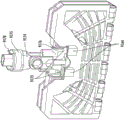
As shown in fig. 8J-8P, the exemplary embodiment of steam wiper 8000 of fig. 8A-8I can be provided with a scrubbing assembly 8500 to perform a scrubbing action in conjunction with a steam blast. The mechanism allows for scrubbing of the area to be cleaned or treated in combination with the steam wind for easy and efficient removal of soiled or difficult to remove stains or spots. In one embodiment, the scrubbing assembly 8500 can extend at least partially into the connector receiving opening of the scrub head 8300.
In one embodiment, the scrubbing assembly 8500 may be directly or indirectly engaged with the connector assembly 8200. For example, the connector assembly 8200 and the scrubbing assembly 8500 can move independently of each other or in relation to each other with a particular orientation of the scrubbing head 8300 relative to the connector assembly 8200. In a different embodiment, the scrubbing assembly 8500 can be directly or indirectly engaged with the scrubbing head 8300 or body 8100.
In the exemplary embodiment shown in fig. 8J-8P, scrubbing assembly 8500 can include a scrubbing substrate 8501, a pair of support arms 8505 and 8506 extending from scrubbing substrate 8501. The support arms 8505, 8506 may be configured to connect directly or indirectly to the connector assembly 8200 and may extend at least partially into the connector receiving opening. Each of the support arms 8505, 8506 (e.g., fig. 8M and 8N, 8O, and 8P) can be configured to be in a collapsed position when the scrubbing assembly is in the retracted mode 8520 (mode 1) and an extended position when the scrubbing assembly is in the scrubbing mode 8510 (mode 2). This embodiment of the scrubbing assembly 8500 can provide the benefit of the scrubbing pad not contacting the floor when not in the scrubbing mode 8510 so that dust or dirt is not redeposited in the cleaning area.
In the normal zone cleaning mode, steam flow is directed to the mop head 8300 and the scrubber assembly 8500 is in the retracted mode 8520, i.e., away from the zone to be cleaned. In the steam wind mode of operation 8401, steam flow is directed to steam wind nozzle assembly 8400, scrubbing assembly 8500 is in scrubbing mode 8510, i.e., support arms 8505, 8506 are extended to allow scrubbing member 8504 to contact the area to be cleaned or treated (e.g., fig. 8M, mode 2). This allows scrubbing of the surface in combination with the steam wind. In one embodiment, the scrubber base is located near the steam air nozzle assembly 8400 to allow the steam air to spread out before the scrubber. This allows for efficient removal of dust, dirt, stubborn stains and messy soils from the area to be cleaned.
In one embodiment, the deployment of the scrubbing assembly 8500 can be controlled by the orientation of the scrubbing head 8300 relative to the connector assembly. The angular orientation of the scrubbing head 8300, which allows steam to be blown outside of the steam blast nozzle assembly 8400, also encourages the deployment of the scrubbing assembly 8500. Deployment of the scrubbing assembly 8500 can also be accomplished by any means, such as a lever mechanism, electrical device, etc. As shown in fig. 8M (mode 1), 8N (mode 1), and 8O, the scrubbing assembly 8500 is in a retracted mode 8520 and the scrubbing head 8300 is in a general area cleaning mode 8303, i.e., in a second position where the scrubbing head 8300 is at a second predetermined angle relative to the connector assembly 8200. As shown in fig. 8M (mode 2), 8N (mode 2), and 8P, the scrubbing assembly is in a scrubbing mode 8510, and the scrubbing head 8300 is in a steam wind mode 8401, i.e., in a first position where the scrubbing head 8300 is at a first predetermined angle relative to the connector assembly 8200.
Fig. 9 illustrates an exemplary embodiment of a wiping head 9100 that can be used to clean or treat a surface, such as, but not limited to, a wooden, tiled, marble, or laminated floor. It will be appreciated that embodiments of the wiping head 9100 described herein can also be used as a treatment device to perform one or more functions of treating or operating on a surface other than cleaning. As shown in fig. 9, an embodiment of a wiping head 9100 can include a frame 9102, flaps 9104, a joint 9106, and at least one cleaning pad 9108.
One skilled in the art will also appreciate that the cleaning pad 9108 can be secured to the flap 9104 in other ways, instead of or in addition to pockets. For example, in some embodiments, Velcro or a Velcro-type adhesive may be used to attach cleaning pad 9108 to flap 9104. At that time, as can be appreciated, the cleaning pad 9108 can be attached to the flaps 9104 in a variety of ways.
The cleaning pad 9108 can be formed from a variety of materials. Different embodiments of cleaning pad 9108 can be adapted for different types of surface treatments. In some embodiments, different embodiments of the cleaning pad 9108 may be interchangeably attached to the cleaning flaps 9104. For example, an embodiment of a first cleaning pad 9108 can be attached to the flap 9104, and an embodiment of a second cleaning pad 9108 used and replaced for another purpose. In embodiments where the processing head 9100 includes multiple faces, the cleaning pad 9108 can be divided into sections corresponding to the faces of the processing head 9100. Each section of the cleaning pad 9108 can be designed for a particular purpose. Also, the user can adjust the wiping head 9100 so that a desired surface can be supported on the cleaning surface, thereby utilizing the most appropriate section of the cleaning pad 9108.
As shown in fig. 11, 11A, 11B, 11C, and 11D, in some embodiments, the flaps 9104 are pivotably attached to a first portion 9150 of the frame 9102 of the wiping head 9100, wherein the flaps 9104 are configured to be pivotably rotatable relative to the frame 9102 between an open position and a closed position. The flaps 9104 can be rotated to an open position to attach and remove a cleaning pad 9108, and locked to a closed position for cleaning. In one embodiment, a hinge may be used to attach flap 9104 to frame 9102.
However, in alternative embodiments, different attachment mechanisms may be used to attach the flaps 9104 to the frame 9102. Hinges or other attachment mechanisms for attaching the flaps 9104 to the frame 9102 may be provided in different locations in different embodiments. In some embodiments, the flaps 9104 can then be rotated about the hinge to either the open position or the closed position. Fig. 11 illustrates one embodiment of a device with flaps 9104 in an open position. Fig. 12B illustrates an embodiment of the device with flaps 9104 in the closed position.
Fig. 11-11D illustrate an embodiment in which a flap 9104 is hingedly or pivotally connected to a first side or portion 9150 of frame 9102 and releasably connected to a second side 9152 of frame 9102. Such an embodiment allows the flaps 9104 to rotate about a hinge on the first side 9150, such that the flaps 9104 can be folded into a closed position and releasably attached to the second side 9152 of the frame 9102. To remove the cleaning pad 9108, the flaps 9104 can be folded outwardly to an open position after the flaps 9104 have been released from the second side edge 9152 of the frame. In some embodiments, first side 9150 and second side 9152 of frame 9102 are opposite sides or opposing sides, as shown in the embodiments found in fig. 11-11D.
In one embodiment, flaps 9104 can be releasably attached to a first side 9150 of frame 9102 and joints 9106 can be pivotally attached to a second side 9152 of frame 9102. In such embodiments, first side 9150 and second side 9152 can be opposite each other.
The embodiment of the wiping head 9100 shown in fig. 12-12H further includes a first flap 9104A and a second flap 9104B. The first and second flaps 9104A, 9104B are pivotably connected to a first side edge 9150 of the frame 9102 along separate first and second hinge axes 9200 (for the first flap 9104A) and 9202 (for the second flap 9104B) as shown in fig. 12-12H. A variety of locking mechanisms may be used in various embodiments to releasably lock flaps 9104A and 9104B to frame 9102 at second side edge 9152 when flaps 9104A and 9104B are folded into a closed position. Also, different embodiments may use different release mechanisms to unlock the flaps 9104A and 9104B from the frame 9102.
As shown in fig. 12-12H, the button release mechanism 9120 can be used to unlock the flaps 9104A and 9104B such that the flaps 9104A and 9104B can be folded open and the cleaning pad 9108 can be removed. The buttons 9120 can be located in a variety of positions on the frame 9102 of the wiping head 9100. The buttons 9120 can also be located at different points on the wiping head 9100 or on the cleaning implement.
As shown in fig. 13-13E, in one embodiment, cleaning pad 9108 can be configured to include one or more foot pads 9130. When a user exerts upward pressure on the frame 9102 and holds the flaps 9104 in place by stepping on the footpads 9130, the frame 9102 may be unlocked and the flaps 9104 released. As can be appreciated, the upward pressure may be provided in different ways in different embodiments. However, in many embodiments, the wiping head 9100 can be attached to a shaft or wand, and a user can apply upward pressure on the frame 9102 simply by pulling upward on the wand or shaft. When a certain pressure is reached, the flaps 9104 will be unconstrained by the locking mechanism and fold open. The user can thus unlock and open flap 9104 by touching the scrub head 9100 with a hand. In some embodiments, pad 9108 can also be removed in the same action, and the user can be able to remove pad 9108 from flap 9104 without using his or her hands. In one such embodiment, the cleaning pad 9108 is attached to the flaps 9104 by pockets 9110. Once the flaps 9104 have been opened, the user can continue to pull the shaft or rod and pull the flaps 9104 out of the cleaning pad 9108, which will be held to the ground by the footpad 9130. The pad 9108 can thus be removed hands-free. It will be appreciated that in other embodiments, other release mechanisms may be used to release the flap 9104, some of which are described elsewhere in this specification, including but not limited to levers.
In another embodiment, cleaning pad 9108 can be attached to flap 9104 by a Velcro or Velcro-type adhesive. The cleaning pad 9108 can also have a footpad sheet 9130. By stepping on the footpad 9130 and pulling the shaft or handle, the user can overcome the Velcro grip and separate the scrubbing head 9100 from the cleaning pad 9108. Thus, the wiping head 9100 will not be constrained by the cleaning pad 9108, while the flaps 9104 will remain in the closed position. This will allow a user to remove the old and potentially hotter cleaning pad 9108 from the wiping head 9100 without touching the cleaning pad with a hand. And, a new cleaning pad 9108 can then be attached to the wiping head 9100.
In one embodiment, the wiping head 9100 can further include a connector assembly 9107. In some embodiments, a connector assembly can be used to connect the wiping head 9100 to a shaft, handle, or wand. An embodiment of a connector assembly 9106 is shown in fig. 15-15G. The connector assembly shown in fig. 15-15G includes an upper portion 9107A and a lower portion 9107B. The connector assembly 9107 can further include a joint 9106 configured to allow the upper portion 9107A and the lower portion 9107B to rotate relative to one another. In some embodiments, the lower portion 9107B can include a yoke 9160. The yoke 9160 can be received in a recess 9162 provided on the frame 9102. In some embodiments, the wiping head 9100 can rotate about the yoke 9160.
Fig. 15-15G illustrate one embodiment of a locking mechanism 9164. However, as can be appreciated, alternative means may be used to lock or unlock the tabs 9104. In this embodiment, the flap 9104 further comprises a catch 9170 extending from the flap 9104. The locking mechanism 9164 is configured to releasably secure the flaps 9104 in the closed position. In some embodiments, locking mechanism 9164 includes a latch 9171 movably connected to frame 9102. When engaged, the latch 9171 holds the catch 9170 in place and prevents the flap 9104 from opening. In other embodiments, the arrangement and operation of the latch 9171 and the catch 9170 with respect to each other is reversed. In such embodiments, the latch 9171 is disposed on the flap 9104 and the catch is movably connected to the frame 9102. In some embodiments, the latch 9171 can be biased to a first latched position in which the latch 9171 is engaged. A spring 9172 may be used to bias the latch 9171 into the first latched position. However, in alternative embodiments, different biasing mechanisms may be employed.
When the latch 9171 is disengaged, the flaps 9104 will be free to fold into the open position. In some embodiments, the latch 9171 is movable from a first latched position to a second latched position by a trigger 9173, the latch 9171 may be disengaged when in the second latched position. When in the first latched position, the latch 9171 engages the catch 9170 and holds the flap 9104 in the closed position. Some embodiments may include a single flip-flop 9173. However, other embodiments may include multiple flip-flops 9173. Fig. 15-15G illustrate an embodiment having two flip-flops 9173. When the trigger 9173 is actuated, the biasing elements 9172 will be compressed and the capturing portions 9170 will be unconstrained by the latches 9171, thereby allowing the flaps 9104 to open.
In the embodiment illustrated in fig. 15-15C, the trigger 9173 can be actuated by a release mechanism 9174 that is configured to interact with the locking mechanism 9164. The position of the locking mechanism 9164 may vary in different embodiments. The interaction between the locking mechanism 9164 and the release mechanism can vary in different embodiments. The release mechanism 9174 includes an upper actuator element 9175 and a lower actuator element 9176. In some embodiments, the upper actuator element 9175 is disposed at least partially in an upper portion 9107A of the connector assembly 9107 and the lower actuator element 9176 is disposed at least partially in a lower portion 9107B of the connector assembly 9107. The connector assembly 9107 may be configured such that the upper and lower actuator elements 9175, 9176 do not interfere with the pivoting function provided by the joint 9106.
The upper actuator element 9175 can further include an upper edge 9178 and a lower edge 9179. In some embodiments, upper actuator element 9175 can have a first position and a second position. In some embodiments, upper actuator element 9175 can be transitioned between a first position and a second position via buttons 9181, as shown in fig. 15G. As can be appreciated, the buttons 9181 can be located in different positions in different embodiments. In some embodiments, the buttons 9181 may be engaged by being pressed in a lateral or axial direction. In the first position, the upper edge 9178 protrudes beyond the upper portion 9107A of the connector assembly 9107. And, when in the second position, the lower edge 9179 protrudes from the upper portion 9107A. In some embodiments, the biasing element 9177 biases the upper edge 9178 and the lower expandable edge into the first position. The pusher mechanism is shown in a first position in fig. 15-15C. In some embodiments, the biasing element 9177 comprises a spring. Such an embodiment is shown in fig. 15-15C. In some embodiments, upper actuator element 9175 can include its own spring to hold the upper actuator element in place, and upper actuator element 9175 is independent of biasing element 9177.
In some embodiments, the upper activator element 9175 can move from a first position to a second position when pressure is applied on the upper edge 9178. The upper activator element 9175 will compress the biasing element 9177. This will cause the upper edge 9178 to retract into the upper assembly 9107.
In some embodiments, lower actuator element 9176 can include a lower edge 9180. The lower actuator element 9176 can be movable between a first position and a second position, wherein a lower edge 9180 of the lower actuator element 9176 protrudes from the lower portion 9107B when the lower actuator element 9176 is in the second position.
The lower edge 9180 of the lower activator element 9176 can also be configured to interact with the trigger 9173 such that the trigger 9173 moves the latch 9171 from the first latched position to the second latched position when the lower activator element 9176 moves from the first position to the second position. As described above, the release mechanism 9174 can interact with the locking mechanism 9164 in different ways to trigger the release of the flaps 9104. In some embodiments, the locking mechanism 9164 may be released by axial movement of the lower edge 180. However, in other embodiments, the lower edge 9180 can be configured to move in a lateral direction, thereby triggering the release of the locking mechanism.
In some embodiments, lower activator element 9176 can be aligned with trigger 9173 such that lower edge 9180 presses against trigger 9173 when lower edge 9180 protrudes from lower portion 9107B. This can overcome the biasing elements 9172 and free the latches 9171 from the catches 9170.
As can be appreciated, pressure can be applied to the upper edge 9178 of the upper actuator element 9175 and cause the upper actuator element 9175 to move from the first position to the second position in different manners in different embodiments. In some embodiments, this can be accomplished by pushing down on a rod, shaft, or handle attached to the connector assembly 9107.
In another embodiment, as shown in fig. 12C-12H, the frame 9102 may be connected to the joints 9106 by external support rods 9140. The frame 9102 may have a recess to receive the outer support rod 9140. However, as can be appreciated, a variety of ways can be used to attach the outer support rods 9140 to the frame 9102. This embodiment may also give the user the freedom to pivot the shaft and handle about the attachment point between the frame 9102 and the outer support rod 9140. Also, in embodiments that include a dual-sided wiping head 9100, the user has the freedom to use either side to clean or treat the surface.
The joint 9106 includes a shaft connection mechanism. As will be appreciated by those skilled in the art, a plurality of connection mechanisms may be employed in different embodiments to connect the joint 9106 to a shaft or handle. As shown in fig. 12, joint 9106 can also have a rotation mechanism that gives the user an additional range of motion. As can be appreciated, the rotational nature of the joint 9106 can be imparted in a variety of ways including, but not limited to, a pivot.
Some embodiments of the processing head 1 may further comprise a flap ejector 9182. One such embodiment is shown in fig. 16. The flap ejectors 9182 may be configured to eject the flaps 9104 to an open position after the flaps 9104 have been released by the locking mechanism 9164. This will facilitate opening of the flaps 9104 so that a user does not have to manually pull the flaps into the open position after the locking mechanism 9164 has been released. In some embodiments, the flap ejector 9182 can include a spring that biases the flap 9104 to the open position. The spring will be compressed when the flap 9104 is in the closed position and will spring out when the locking mechanism is released. As can be appreciated, different embodiments can include different numbers of spring ejectors 9182 and in different positions. Also, the flap ejectors 9182 may comprise different forms in different embodiments.
Some embodiments of the processing head 9100 can further include a coupling element 9183, as shown in fig. 16. The linking elements 9183 can be configured to link the flaps 9104 to coordinate the movement of the flaps. In such an embodiment, the foils 9104 would rotate simultaneously.
In operation, a method of processing a surface using processing head 9100 comprises: a frame 9102 having a first portion 9150 is provided and a flap 9104 is pivotally connected to the first portion 9150 of the frame 9102, wherein the flap 9104 pivotally rotates relative to the frame 9102 to an open position. The method further includes providing a cleaning pad 9108 and removably attaching the cleaning pad 9108 to the flap 9104. The method can further include providing a locking mechanism 9164, wherein providing a locking mechanism 9164 includes providing a catch 9170 extending from a flap 9104, a movable latch 9171, and a trigger 9173. The flaps 9104 can be rotated to the closed position and locked with the locking mechanism 9164. The method further includes providing a connecting assembly 9107 including an upper portion 9107A, a lower portion 9107B, and a joint 9106. The connection assembly is pivotally connected to the frame. Surface treatment with flaps 9104 locked in the closed position is achieved as desired with cleaning pad 9108 attached by pivoting treatment head 9100 about attachment assembly 9107 and with upper portion 9107A and lower portion 9107B rotated relative to each other through joints 9106. The method further includes providing a release mechanism 9174, wherein providing a release mechanism 9174 includes providing an upper actuator element 9175 disposed at least partially in an upper portion 9107A of the connector assembly 9107 and providing a lower actuator element 9176 disposed at least partially in a lower portion 9107B of the connector assembly 9107. Finally, after the surface is processed, the method includes releasing the catch 9170 from the latch 9171 by moving the upper activator elements 9175 from the first position to the second position, thereby moving the lower activator elements 9176 from the first position to the second position engaging the trigger 9173.
Fig. 17 shows an embodiment of a surface treatment system 9320 with enhanced rotational and modular features. In particular, the system 9320 includes a steam application device 9322 and a portable steamer 9324. The portable steamer 9324 is constructed and arranged to be conveniently attached to and detached from the steam application device 9322 (e.g., as indicated by arrow 9326). The steam application 9322 comprises a body 9330, a rotating assembly 9332, an applicator 934 and a wiper handle 9336. The main body 9330 includes a first end 9340 directly connected to the wiper handle 9336, a second end 9342 directly connected to the swivel assembly 9332, and an intermediate portion 9344 disposed between the first and second ends 9340, 9342. The rotating assembly 9332 connects the body 9330 to the applicator 9334 and operates in the manner of a universal joint to allow the body 9330 and the applicator 9334 to rotate relative to each other.
As best seen in fig. 17, the wiper handle 9336, body 9330, swivel assembly 9332, and applicator 9334 are provided in a robust, in-line configuration that forms a wiper 9346 having a central axis 9348. In this configuration, a user can efficiently and conveniently clean the surface 9350 with the applicator 9334 while manipulating the wiper handle 9336. With this C-shaped geometry, main body 9330 cradles portable steamer 9324 in a manner that securely and reliably supports portable steamer 9324 when portable steamer 9324 is attached to main body 9330. In some arrangements, the central axis 9348 of the wiper 9346 passes through the cavity 9352 (fig. 17), but the configuration of the body 9330 provides sufficient support strength to maintain the robustness of the wiper 9346 and thereby enables a user to apply a significant wiping force to the surface 9350 for effective cleaning. In addition, this geometry enables the portable steamer 9324 to have a relatively large but modular form factor, enabling the portable steamer 9324 to be detached from the steam application device 9322 in a simple lifting manner and attached to the steam application device 9322 in a simple insertion manner.
It should be appreciated that in the surface treating system 100 shown in FIG. 1A, various combinations of the body 200 and the scrub head 400 can be assembled together to form a surface treating appliance. The universal joint 310 may be configured to connect to various combinations of the body 200 and the mop head 400. The body may be any of the bodies shown in fig. 1B and/or fig. 17. The wiping head may be any of the wiping heads shown in figures 1-17. For example, the surface treatment system in one or more embodiments can allow for any combination of: 1) the combination of a wiping head as shown at least in figure 1D with either of the bodies shown in figure 1B or figure 17; 2) the combination of a wiping head as shown at least in figures 2-6 with either of the bodies shown in figure 1B or figure 17; 3) the combination of a wiping head as shown at least in figures 7-8 with either of the bodies shown in figure 1B or figure 17; 4) a combination of a wiping head as shown at least in figures 9-16 with either of the bodies shown in figure 1B or figure 17; 5) a combination of a wiping head as shown at least in figure 17 and either of the bodies shown in figure 1B or figure 17. It should be noted that the body and/or the wiping head shown in fig. 1-17 may not be considered limiting.
While various embodiments in accordance with the disclosed principles have been described above, it should be understood that they have been presented by way of example only, and not limitation. Thus, the breadth and scope of an exemplary embodiment described herein should not be limited by any of the above-described exemplary embodiments, but should be defined only in accordance with the following claims and their equivalents issuing from this disclosure. Additionally, the above advantages and features are provided in described embodiments, but are not limited to application of these issued claims to methods and structures for achieving any or all of the above advantages.
Comparison, measurement, and timing terms, such as "at that time," "equivalent," "during … …," "complete," and the like, are to be understood as meaning "substantially simultaneously," "substantially equivalent," "substantially during … …," "substantially complete," and the like, wherein "substantially" indicates that such comparison, measurement, and timing is practical to achieve the desired result, implicitly or explicitly claimed. Terms relating to relative positions of elements, such as "about," "near," and "adjacent" will mean sufficiently close to interact with corresponding system elements to have a material effect.
Further, the preamble herein is provided for meeting the requirements of 37c.f.r 1.77 or for providing organizational cues. These initial portions are not intended to limit or define the invention as set forth in any claims that may issue from this disclosure. In particular and by way of example, although the preamble refers to a "technical field", such claims are not limited by the language chosen in the preamble to describe the so-called technical field. In addition, the technical description in the "background" section is not to be construed as an admission that the technology precedes any invention of the present disclosure. The summary of the invention is not to be considered a feature of the invention set forth in the issued claims. In addition, any reference in this disclosure to a separate "invention" should not be taken to argue that there is only a single point of innovation in this disclosure. This invention may be embodied in several forms depending upon the limitations of the various claims set forth in this disclosure, and accordingly such claims define the invention and its equivalents to be protected thereby. In all respects, the scope of such claims will be considered with the benefit of the present disclosure, and such claim scope should not be considered as limited by the introductory portion of this document.
Claims (14)
1. An apparatus for surface treatment, comprising:
a source of steam;
a main body;
a wiping head comprising:
a first opposing surface and a second opposing surface, wherein the first opposing surface and the second opposing surface are configured to output steam;
a mop head steam inlet configured to receive steam; and
a fluid conduit extending from the mop head steam inlet to the first and second opposing surfaces of the mop head defining at least first and second mop head steam paths leading to the first and second opposing surfaces of the mop head, respectively; and
a connector assembly configured to receive steam from the steam source and direct steam to the wiping head, the connector assembly including a universal joint and a connector housing connected to the universal joint, wherein a first end portion of the universal joint is pivotally connected to the body and a second end portion of the universal joint is pivotally connected to the wiping head;
wherein the wiping head is configured to rotate about a transverse axis relative to the connector assembly and the wiping head is configured to be oriented relative to the connector assembly in a first position and a second position, wherein:
either the first or second opposing surfaces of the wiping head face upward and are oriented at a first predetermined angle relative to the connector assembly when the wiping head is in the first position; and is
When the wiping head is in the second position, either the first or second opposing surfaces of the wiping head face upward and are oriented at a second predetermined angle relative to the connector assembly, wherein the first and second predetermined angles are different; and
a changer at least partially disposed in the fluid conduit of the wiping head, the changer configured to move between a first changer position located along the first wiping head vapor path and a second changer position located along the second wiping head vapor path;
wherein when the wiping head is in the second position and the second opposing surface of the wiping head faces upwardly and is oriented at a second predetermined angle relative to the connector assembly, the switch is positioned in the first switch position thereby blocking the second wiping head vapor path and allowing vapor to be provided through the first wiping head vapor path and output on the first opposing surface of the wiping head; and is
Wherein when the wiping head is in the second position and the first opposing surface of the wiping head faces upwardly and is oriented at a second predetermined angle relative to the connector assembly, the switch is positioned in the second switch position thereby blocking the first wiping head vapor path and allowing vapor to be provided through the second wiping head vapor path and output on the second opposing surface of the wiping head.
2. The apparatus of claim 1, wherein the transformation means comprises:
a transducer body at least partially disposed in the fluid conduit, the transducer body having a first end portion and a second end portion; and
first and second shoulders extending outwardly from the first and second end portions, respectively;
wherein the first shoulder and the changer body are configured to cooperate to block the second wiping head vapor path when the changer is in the first changer position; and is
Wherein the second shoulder and the changer body are configured to cooperate to block the first wiping head vapor path when the changer is in the second changer position.
3. The apparatus of claim 2, wherein the first shoulder comprises a sealing element disposed on a shoulder surface facing the second shoulder, and the second shoulder comprises a sealing element disposed on a shoulder surface facing the first shoulder.
4. The apparatus of claim 3, wherein the shift device comprises a ball valve including a sealing element disposed within a cavity defined in the fluid conduit, the sealing element configured to move between a first shift device position located along the first wiper head vapor path and a second shift device position located along the second wiper head vapor path.
5. The apparatus of claim 1, wherein the first predetermined angle is an acute angle and the second predetermined angle is an obtuse angle.
6. An apparatus for surface treatment, comprising:
a source of steam;
a main body;
a wiping head; and
a connector assembly configured to receive steam from the steam source and direct steam to the mop head;
wherein the connector assembly comprises a universal joint and a connector housing connected to the universal joint, wherein a first end portion of the universal joint is pivotally connected to the body and a second end portion of the universal joint is pivotally connected to the wiping head;
wherein the wiping head is configured to rotate about a transverse axis relative to the connector assembly and the wiping head comprises first and second opposing surfaces; and is
Wherein the wiping head is configured to be oriented relative to the connector assembly in a first position and a second position, wherein:
either the first or second opposing surfaces of the wiping head face upward and are oriented at a first predetermined angle relative to the connector assembly when the wiping head is in the first position; and is
When the wiping head is in the second position, either the first or second opposing surfaces of the wiping head face upward and are oriented at a second predetermined angle relative to the connector assembly, wherein the first and second predetermined angles are different;
wherein the first and second opposing surfaces of the wiping head are configured to output steam, and the wiping head further comprises:
a mop head steam inlet configured to receive steam;
first and second vapor chambers defined in the wiping head on the first and second opposing surfaces of the wiping head, respectively;
a fluid conduit extending from the mop head steam entry of the mop head into the first and second steam chambers,
wherein the fluid conduit and the first steam chamber define a first wiping head steam path, the fluid conduit and the second steam chamber define a second wiping head steam path; and
a changer configured to move between a first changer position and a second changer position in the wiping head,
wherein, when the wiping head is in the second position and the second opposing surface of the wiping head faces upward and is oriented at the second predetermined angle relative to the connector assembly, the changer is positioned in the first changer position, blocking the second wiping head vapor path and allowing vapor to be provided to the first vapor chamber through the first wiping head vapor path for output on the first opposing surface of the wiping head, and
wherein, when the wiping head is in the second position and the first opposing surface of the wiping head faces upward and is oriented at the second predetermined angle relative to the connector assembly, the changer is positioned in the second changer position, blocking the first wiping head vapor path and allowing vapor to be provided to the second vapor chamber through the second wiping head vapor path for output on the second opposing surface of the wiping head.
7. An apparatus for surface treatment, comprising:
a source of steam;
a main body;
a wiping head; and
a connector assembly configured to receive steam from the steam source and direct steam to the mop head,
wherein the connector assembly comprises a universal joint and a connector housing connected to the universal joint, wherein a first end portion of the universal joint is pivotally connected to the body and a second end portion of the universal joint is pivotally connected to the wiping head;
wherein the wiping head is configured to rotate about a transverse axis relative to the connector assembly and includes first and second opposing surfaces, wherein the first and second opposing surfaces are configured to output steam; and is
Wherein the wiping head is configured to be oriented relative to the connector assembly in a first position and a second position, wherein:
either the first or second opposing surfaces of the wiping head face upward and are oriented at a first predetermined angle relative to the connector assembly when the wiping head is in the first position; and is
When the wiping head is in the second position, either the first or second opposing surfaces of the wiping head face upward and are oriented at a second predetermined angle relative to the connector assembly, wherein the first and second predetermined angles are different;
wherein:
the body includes a pivoting steam port; and is
The wiping head includes:
a first vapor chamber comprising first vapor chamber inlets configured to output vapor on the first opposing surface of the wiping head; and
a second steam chamber including second steam chamber inlets, the second steam chamber configured to output steam on the second opposing surface of the wiping head,
wherein, when the wiping head is in the second position with the second opposing surface facing upwardly, the first steam chamber inlets are configured to align with the pivoting steam ports of the main body, allowing steam to be provided to the first steam chamber and output on the first opposing surface of the wiping head, and
wherein, when the wiping head is in the second position with the first opposing surface facing upward, the second steam chamber inlets are configured to align with the pivoting steam ports of the main body, thereby allowing steam to be provided to the second steam chamber and output on the second opposing surface of the wiping head.
8. An apparatus for surface treatment, comprising:
a source of steam;
a main body;
a wiping head; and
a connector assembly configured to receive steam from the steam source and direct steam to the mop head;
wherein the connector assembly comprises a universal joint and a connector housing connected to the universal joint, wherein a first end portion of the universal joint is pivotally connected to the body and a second end portion of the universal joint is pivotally connected to the wiping head;
wherein the wiping head is configured to rotate about a transverse axis relative to the connector assembly and includes first and second opposing surfaces, wherein the first and second opposing surfaces are configured to output steam; and is
Wherein the wiping head is configured to be oriented relative to the connector assembly in a first position and a second position, wherein:
either the first or second opposing surfaces of the wiping head face upward and are oriented at a first predetermined angle relative to the connector assembly when the wiping head is in the first position; and is
When the wiping head is in the second position, either the first or second opposing surfaces of the wiping head face upward and are oriented at a second predetermined angle relative to the connector assembly, wherein the first and second predetermined angles are different;
wherein the connector housing comprises:
a connector steam inlet configured to receive steam from the steam source;
a connector steam conduit defining at least a first connector steam path and a second connector steam path, wherein the first connector steam path and the second connector steam path are configured to direct steam from the connector steam inlet; and
a steam wind nozzle assembly disposed at least partially in the first connector steam path;
wherein:
when the wiping head is oriented at the first predetermined angle relative to the connector assembly, a flow of steam is directed through the first connector steam path to the steam wind nozzle assembly, allowing steam to be discharged in a steam wind pattern, and
when the wiping head is oriented at the second predetermined angle relative to the connector assembly, steam flow is directed through the second connector steam path to the wiping head, allowing steam to be discharged in a zone cleaning mode.
9. The apparatus of claim 8, wherein the steam wind nozzle assembly includes a nozzle inlet portion, a nozzle intermediate portion, and a nozzle outlet portion.
10. The apparatus of claim 9, wherein the nozzle inlet portion of the steam blast nozzle assembly defines a first cross-sectional surface area, the nozzle intermediate portion defines a second cross-sectional surface area, and the nozzle outlet portion defines a third cross-sectional surface area, wherein the second cross-sectional surface area is smaller than the first cross-sectional surface area and the third cross-sectional surface area.
11. The apparatus of claim 10, wherein the nozzle outlet portion of the steam wind nozzle assembly comprises a conical nozzle outlet portion; wherein the conical nozzle outlet portion produces a conical steam wind profile.
12. The apparatus of claim 8, wherein the connector housing further defines a valve mechanism configured to switchably direct a flow of steam through the first connector steam path to the steam wind nozzle assembly or through the second connector steam path to the wiping head, wherein the valve mechanism defines at least a portion of the first connector steam path or at least a portion of the second connector steam path, or defines both at least a portion of the first connector steam path and at least a portion of the second connector steam path.
13. The apparatus of claim 12, wherein the valve mechanism is configured to define a first baffle and a second baffle;
wherein the first and second baffles cooperate to form at least a portion of the first connector steam path or at least a portion of the second connector steam path depending on the relative movement of the first and second baffles;
wherein the first and second shutters have a first relative movement when the wiping head is oriented at a first predetermined angle relative to the connector assembly and a second relative movement when the wiping head is oriented at a second predetermined angle relative to the connector assembly;
wherein the second connector vapor path is blocked with a first relative movement of the first and second baffle members, and wherein the first connector vapor path is blocked with a second relative movement of the first and second baffle members.
14. The apparatus of claim 12, wherein the first and second opposing surfaces of the wiping head are configured to output steam, and the wiping head further comprises:
a changer configured to move between a first changer position and a second changer position in the wiping head,
wherein, when the wiping head is in the second position and the second opposing surface of the wiping head faces upwardly and is oriented at a second predetermined angle relative to the connector assembly, the changer is positioned in the first changer position, thereby allowing steam to be output only on the first opposing surface of the wiping head, and
wherein, when the wiping head is in the second position and the first opposing surface of the wiping head faces upwardly and is oriented at a second predetermined angle relative to the connector assembly, the changer is positioned in the second changer position, thereby allowing steam to be output only on the second opposing surface of the wiping head.
Priority Applications (1)
| Application Number | Priority Date | Filing Date | Title |
|---|---|---|---|
| CN202110220270.3A CN112998611B (en) | 2015-05-26 | 2016-05-26 | Wiping head and method for treating a surface |
Applications Claiming Priority (5)
| Application Number | Priority Date | Filing Date | Title |
|---|---|---|---|
| US201562166636P | 2015-05-26 | 2015-05-26 | |
| US62/166,636 | 2015-05-26 | ||
| US201562245195P | 2015-10-22 | 2015-10-22 | |
| US62/245,195 | 2015-10-22 | ||
| PCT/US2016/034498 WO2016191627A1 (en) | 2015-05-26 | 2016-05-26 | Surface treatment apparatuses and methods |
Related Child Applications (1)
| Application Number | Title | Priority Date | Filing Date |
|---|---|---|---|
| CN202110220270.3A Division CN112998611B (en) | 2015-05-26 | 2016-05-26 | Wiping head and method for treating a surface |
Publications (2)
| Publication Number | Publication Date |
|---|---|
| CN107708516A CN107708516A (en) | 2018-02-16 |
| CN107708516B true CN107708516B (en) | 2021-03-23 |
Family
ID=57393192
Family Applications (2)
| Application Number | Title | Priority Date | Filing Date |
|---|---|---|---|
| CN201680030827.4A Active CN107708516B (en) | 2015-05-26 | 2016-05-26 | Surface treatment apparatus and method |
| CN202110220270.3A Active CN112998611B (en) | 2015-05-26 | 2016-05-26 | Wiping head and method for treating a surface |
Family Applications After (1)
| Application Number | Title | Priority Date | Filing Date |
|---|---|---|---|
| CN202110220270.3A Active CN112998611B (en) | 2015-05-26 | 2016-05-26 | Wiping head and method for treating a surface |
Country Status (7)
| Country | Link |
|---|---|
| EP (2) | EP3845107B1 (en) |
| JP (3) | JP6838001B2 (en) |
| KR (2) | KR102546433B1 (en) |
| CN (2) | CN107708516B (en) |
| AU (3) | AU2016268418B2 (en) |
| CA (2) | CA2987313C (en) |
| WO (1) | WO2016191627A1 (en) |
Families Citing this family (6)
| Publication number | Priority date | Publication date | Assignee | Title |
|---|---|---|---|---|
| PL3833490T3 (en) * | 2018-08-09 | 2023-01-23 | Alfred Kärcher SE & Co. KG | Surface-cleaning head |
| CN110338725A (en) * | 2019-07-11 | 2019-10-18 | 尚科宁家(中国)科技有限公司 | Steam appliance |
| CN110916581B (en) * | 2019-12-10 | 2021-04-13 | 刘素凤 | Rotary turnover type steam mop |
| GB2606134B (en) * | 2021-03-26 | 2023-08-02 | Dextron Tech Ltd | Surface treatment tool |
| DE202021102732U1 (en) | 2021-05-19 | 2021-05-27 | Leifheit Aktiengesellschaft | Attachment for a steam cleaning device and steam cleaning device with weed killing function |
| KR102580346B1 (en) * | 2021-08-03 | 2023-09-19 | 임종혁 | Liquid spray typed mop |
Citations (7)
| Publication number | Priority date | Publication date | Assignee | Title |
|---|---|---|---|---|
| CN201481333U (en) * | 2008-06-27 | 2010-05-26 | 尤罗普罗操作公司 | Steam mop |
| WO2010120312A1 (en) * | 2009-04-17 | 2010-10-21 | Euro-Pro Operating, Llc | Adapter for use with a mop |
| US20100269282A1 (en) * | 2009-04-24 | 2010-10-28 | Euro-Pro Operating, Llc | Shaggy fabric towel steam pocket for a steam appliance |
| CN201996485U (en) * | 2008-05-09 | 2011-10-05 | 尤罗普罗操作公司 | Steam appliance, steam mop, steam frame assembly and related devices |
| CN102652660A (en) * | 2011-03-04 | 2012-09-05 | 碧洁家庭护理有限公司 | Surface cleaning apparatus with pivoting manifold |
| CN103565354A (en) * | 2012-08-03 | 2014-02-12 | 戴森技术有限公司 | Floor tool for vacuum cleaning appliance |
| CN203841629U (en) * | 2013-03-01 | 2014-09-24 | 碧洁家庭护理有限公司 | Surface cleaning device |
Family Cites Families (21)
| Publication number | Priority date | Publication date | Assignee | Title |
|---|---|---|---|---|
| DE2551678C3 (en) * | 1975-11-18 | 1978-12-07 | Nwg Nord-West Gebaeudereinigung Gmbh & Co Kg, 4100 Duisburg | Floor wiper |
| US5461749A (en) * | 1994-05-31 | 1995-10-31 | Minnesota Mining And Manufacturing Company | Floor mop and cleaning system |
| JPH10286208A (en) * | 1997-04-16 | 1998-10-27 | Lion Corp | Form-changeable mop |
| JP2002263042A (en) * | 2001-03-08 | 2002-09-17 | Matsushita Electric Ind Co Ltd | Device for cleaning |
| EP1610662A4 (en) * | 2003-04-04 | 2009-03-18 | Seung Jae Lee | A floor mop capable of using both sides |
| DE10343324A1 (en) * | 2003-09-11 | 2005-04-14 | Alfred Kärcher Gmbh & Co. Kg | Device for ejecting a mop cover |
| JP4578300B2 (en) * | 2005-03-30 | 2010-11-10 | 株式会社ダスキン | Cleaning member holder |
| JP4667188B2 (en) * | 2005-09-27 | 2011-04-06 | 三洋電機株式会社 | Steam iron |
| US20080236635A1 (en) * | 2006-07-31 | 2008-10-02 | Maximilian Rosenzweig | Steam mop |
| CN201026181Y (en) * | 2007-03-30 | 2008-02-27 | 朱雪林 | Two-sided mop |
| AU2009201017A1 (en) * | 2009-03-13 | 2010-09-30 | Euro-Pro Operating Llc | Handle for surface cleaning apparatus |
| CN201445489U (en) * | 2009-05-11 | 2010-05-05 | 惠州强雳日常用品制造有限公司 | Fixing seat for mop head |
| AU2010246496B2 (en) * | 2009-12-03 | 2013-11-07 | Bissell Inc. | Steam mop with shuttling steam distributor |
| JP5552372B2 (en) | 2010-06-02 | 2014-07-16 | 株式会社ダスキン | Wiping body insertion part rotation type cleaning tool |
| JP2012075669A (en) * | 2010-10-01 | 2012-04-19 | Iris Ohyama Inc | Mop |
| CN202184697U (en) * | 2011-07-22 | 2012-04-11 | 苏州海力电器有限公司 | Electric steam mop |
| WO2013029040A1 (en) * | 2011-08-25 | 2013-02-28 | Euro-Pro Operating Llc | Steam cleaning appliance with vibration and heating components |
| GB2504678B (en) * | 2012-08-03 | 2014-11-26 | Dyson Technology Ltd | A floor tool for a vacuum cleaning appliance |
| JP6084791B2 (en) | 2012-08-21 | 2017-02-22 | 株式会社ニフコ | Rotating body locking mechanism |
| JP2014085444A (en) * | 2012-10-22 | 2014-05-12 | Sei Optifrontier Co Ltd | Connector and operation member and method for inserting and extracting connector |
| JP2015066360A (en) | 2013-09-30 | 2015-04-13 | 株式会社ダスキン | Opening and closing combined type wiper gripping tool and cleaning utensil |
-
2016
- 2016-05-26 CA CA2987313A patent/CA2987313C/en active Active
- 2016-05-26 EP EP20206348.3A patent/EP3845107B1/en active Active
- 2016-05-26 KR KR1020177037303A patent/KR102546433B1/en active IP Right Grant
- 2016-05-26 WO PCT/US2016/034498 patent/WO2016191627A1/en unknown
- 2016-05-26 CN CN201680030827.4A patent/CN107708516B/en active Active
- 2016-05-26 AU AU2016268418A patent/AU2016268418B2/en active Active
- 2016-05-26 CN CN202110220270.3A patent/CN112998611B/en active Active
- 2016-05-26 EP EP16800763.1A patent/EP3302207B1/en active Active
- 2016-05-26 JP JP2017561704A patent/JP6838001B2/en active Active
- 2016-05-26 KR KR1020237019994A patent/KR20230093071A/en not_active Application Discontinuation
- 2016-05-26 CA CA3208217A patent/CA3208217A1/en active Pending
-
2020
- 2020-12-21 JP JP2020211395A patent/JP7200206B2/en active Active
- 2020-12-21 JP JP2020211396A patent/JP7201655B2/en active Active
-
2021
- 2021-03-16 AU AU2021201648A patent/AU2021201648B9/en active Active
-
2023
- 2023-03-17 AU AU2023201663A patent/AU2023201663A1/en active Pending
Patent Citations (7)
| Publication number | Priority date | Publication date | Assignee | Title |
|---|---|---|---|---|
| CN201996485U (en) * | 2008-05-09 | 2011-10-05 | 尤罗普罗操作公司 | Steam appliance, steam mop, steam frame assembly and related devices |
| CN201481333U (en) * | 2008-06-27 | 2010-05-26 | 尤罗普罗操作公司 | Steam mop |
| WO2010120312A1 (en) * | 2009-04-17 | 2010-10-21 | Euro-Pro Operating, Llc | Adapter for use with a mop |
| US20100269282A1 (en) * | 2009-04-24 | 2010-10-28 | Euro-Pro Operating, Llc | Shaggy fabric towel steam pocket for a steam appliance |
| CN102652660A (en) * | 2011-03-04 | 2012-09-05 | 碧洁家庭护理有限公司 | Surface cleaning apparatus with pivoting manifold |
| CN103565354A (en) * | 2012-08-03 | 2014-02-12 | 戴森技术有限公司 | Floor tool for vacuum cleaning appliance |
| CN203841629U (en) * | 2013-03-01 | 2014-09-24 | 碧洁家庭护理有限公司 | Surface cleaning device |
Also Published As
| Publication number | Publication date |
|---|---|
| JP7201655B2 (en) | 2023-01-10 |
| KR20180020175A (en) | 2018-02-27 |
| KR20230093071A (en) | 2023-06-26 |
| EP3845107B1 (en) | 2024-08-07 |
| JP2021049403A (en) | 2021-04-01 |
| AU2023201663A1 (en) | 2023-04-13 |
| CA2987313C (en) | 2024-01-02 |
| EP3302207A1 (en) | 2018-04-11 |
| AU2021201648B2 (en) | 2023-05-25 |
| WO2016191627A1 (en) | 2016-12-01 |
| AU2016268418A1 (en) | 2018-01-25 |
| CA3208217A1 (en) | 2016-12-01 |
| EP3845107A1 (en) | 2021-07-07 |
| CN107708516A (en) | 2018-02-16 |
| AU2021201648A1 (en) | 2021-04-08 |
| CA2987313A1 (en) | 2016-12-01 |
| KR102546433B1 (en) | 2023-06-21 |
| JP2021049402A (en) | 2021-04-01 |
| AU2016268418B2 (en) | 2021-04-15 |
| JP2018521724A (en) | 2018-08-09 |
| EP3302207B1 (en) | 2021-02-24 |
| AU2021201648B9 (en) | 2023-06-15 |
| JP6838001B2 (en) | 2021-03-17 |
| EP3302207A4 (en) | 2019-04-17 |
| CN112998611B (en) | 2023-04-11 |
| CN112998611A (en) | 2021-06-22 |
| JP7200206B2 (en) | 2023-01-06 |
Similar Documents
| Publication | Publication Date | Title |
|---|---|---|
| CN107708516B (en) | Surface treatment apparatus and method | |
| EP2611345B1 (en) | Surface cleaning machine | |
| US9743819B2 (en) | Floor mop with concentrated cleaning feature | |
| CN105208907B (en) | Floor cleaner including sterilizing pattern | |
| US9179815B2 (en) | Floor mop with removable base plate | |
| CN105358030B (en) | Steam appliance | |
| EP3099212A1 (en) | Surface cleaning apparatus | |
| TW200829201A (en) | Surface treating appliance | |
| US20040237228A1 (en) | Power scrubber | |
| US20110030724A1 (en) | Multifunction Pressure Washer | |
| CN104138243B (en) | Steam cleaner | |
| EP1529478B1 (en) | Power scrubber | |
| JPH09182631A (en) | Cleaning device provided with brush which can be stored | |
| CN205031186U (en) | A base for surface cleaning device | |
| KR20240087106A (en) | A combination steam injector and steam cleaner | |
| AU2019236607A1 (en) | Cleaning Tool |
Legal Events
| Date | Code | Title | Description |
|---|---|---|---|
| PB01 | Publication | ||
| PB01 | Publication | ||
| SE01 | Entry into force of request for substantive examination | ||
| SE01 | Entry into force of request for substantive examination | ||
| GR01 | Patent grant | ||
| GR01 | Patent grant |