CN107620334B - Pool bottom sludge cleaning device - Google Patents
Pool bottom sludge cleaning device Download PDFInfo
- Publication number
- CN107620334B CN107620334B CN201711008640.7A CN201711008640A CN107620334B CN 107620334 B CN107620334 B CN 107620334B CN 201711008640 A CN201711008640 A CN 201711008640A CN 107620334 B CN107620334 B CN 107620334B
- Authority
- CN
- China
- Prior art keywords
- frame
- fixedly connected
- silt
- driving
- mobile
- Prior art date
- Legal status (The legal status is an assumption and is not a legal conclusion. Google has not performed a legal analysis and makes no representation as to the accuracy of the status listed.)
- Active
Links
Images
Abstract
The invention discloses a pool bottom sludge cleaning device, which comprises a left frame, wherein the top of the right side of the left frame is fixedly connected with a top frame, the right side of the top frame is fixedly connected with a right frame, a partition plate is fixedly connected between two sides of the inner wall of the left frame, the top of the partition plate is fixedly connected with a first motor, and one end of an output shaft of the first motor is fixedly connected with a first bevel gear. This bottom of the pool silt cleaning device has reached the mesh that is convenient for inhale silt head and remove, is convenient for realize carrying out the desilting work to the bottom of the pool on a large scale, and the use of people of being convenient for is convenient for drive inhale the lift of silt head, can adsorb the silt of different co-altitude, improves the desilting effect, need not multiple desilting, has improved work efficiency, prevents to inhale the jam of silt head, avoids influencing the going on of desilting work, the installation of the device of being convenient for to improved the stability of device, prolonged device's life.
Description
Technical Field
The invention relates to the technical field of sludge cleaning devices, in particular to a pool bottom sludge cleaning device.
Background
The silt is deposited in still water or slow running water environment, is formed by physical chemistry and biochemistry, is unconsolidated soft fine particles or extremely fine particles, belongs to modern recent sediment, can be powdery or clay according to granularity composition, is extremely small in fine sand or extremely fine sand, is mainly composed of illite and montmorillonite, is mainly composed of illite and kaolinite, is very sensitive to natural structural change of the silt, can be automatically restored after the structure and strength thereof are damaged due to the fact that the structure is thixotropic, is not suitable for being used as a natural foundation, can cause uneven settlement, cracks, incline and influence normal use of the building, can be used for building by adopting manual reinforcement measures such as compaction and tamping, can be used for accelerating the solidification of the silt by using vertical wells, can be used for adopting column bases or can be used for adopting structural measures such as rigid ring beams, settlement and the like on the upper part of the building, so as to ensure the stability of a stable seam of the building.
The cultivation pond or cultivate the pond and often produce more silt after using a period, clear up silt at present and mainly rely on the manual work to go on, waste time and energy to current silt cleaning equipment, inefficiency takes place to block up the condition of inhaling the silt head easily, brings very big influence for dredging work.
Disclosure of Invention
Aiming at the defects of the prior art, the invention provides a pool bottom sludge cleaning device, which solves the problems that the existing sludge cleaning equipment is low in efficiency and easy to block a sludge suction head and greatly influences dredging work because the existing sludge cleaning equipment mainly relies on manual work to clean sludge.
In order to achieve the above purpose, the invention is realized by the following technical scheme: the utility model provides a pond bottom silt cleaning device, includes left frame, the top fixedly connected with top frame on left side frame right side, the right side fixedly connected with right side frame of top frame, fixedly connected with baffle between the both sides of left side frame inner wall, the first motor of top fixedly connected with of baffle, the one end fixedly connected with first conical gear of first motor output shaft, one side meshing of first conical gear has second conical gear, the axle center department fixedly connected with pivot of second conical gear, the left end of pivot is connected with the left side rotation of left side frame inner wall, the right-hand member of pivot runs through left side frame and top frame in proper order and extends to the inside of top frame, the pivot is located the inside one end fixedly connected with lead screw of top frame, the both ends of lead screw are connected with the both sides rotation of top frame inner wall respectively, the surface screw thread connection of lead screw has the movable block, the bottom of movable block runs through the top frame and extends to the outside of top frame, the one end fixedly connected with mobile device that the movable block is located the outside the top frame, the bottom fixedly connected with mobile device has the bottom fixedly connected with mobile device, the bottom fixedly connected with bottom of mobile device and top end, the bottom of top rod and the top end that the top frame has the rotation stability connects with the top, the bottom is connected with the steady rest.
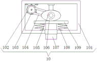
Preferably, the mobile device includes the removal frame, the bottom fixed connection of the top of removal frame and movable block, the bottom fixedly connected with second motor of removal frame inner wall, the one end fixedly connected with first belt pulley of second motor output shaft, the surface of first belt pulley is connected with the second belt pulley through belt drive, the fixed surface of second belt pulley is connected with the cam, the axle center department of cam passes through cam seat and the top fixed connection of removal frame inner wall, the bottom transmission of cam is connected with the movable plate, the both sides of movable plate bottom all fixedly connected with spring, the bottom of spring and the bottom fixed connection of removal frame inner wall, the bottom fixedly connected with movable rod of movable plate, the bottom of movable rod runs through the removal frame and extends to the outside of removal frame, the one end that the movable rod is located the outside of removal frame and the top fixed connection of motion device.
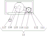
Preferably, the motion device comprises an outer frame, the top of outer frame and the bottom fixed connection of movable rod, the bottom fixedly connected with third motor of outer frame inner wall, the first runner of one end fixedly connected with of third motor output shaft, the surface of first runner is connected with the second runner through rotating the belt drive, the fixed surface of second runner is connected with the carousel, the surface rotation of carousel is connected with the push rod, the bottom of push rod runs through the outer frame and extends to the outside of outer frame, the push rod is located the outside one end of outer frame and is connected with the top rotation of inhaling the silt head.
Preferably, the diaphragm is fixedly connected with between the both sides of right frame inner wall to the bottom fixedly connected with album of right frame inner wall is cut out the silt frame, the top intercommunication that gathers the silt frame has out the silt pipe, the top that goes out the silt pipe runs through the diaphragm and extends to the top of diaphragm, the one end intercommunication that goes out the silt pipe and is located the diaphragm top has the silt pump of inhaling, the left side intercommunication that inhales the silt pump has into the silt pipe, the left end that advances the silt pipe runs through the right frame and extends to the outside of right frame, the one end intercommunication that advances the silt pipe and be located the outside of right frame has the hose, the one end of hose and one side intercommunication that inhales the silt head.
Preferably, the bottoms of the left frame and the right frame are fixedly connected with a bottom plate, and the bottom of the bottom plate is fixedly connected with a mounting frame.
Preferably, the top fixedly connected with slider of movable block, the slide rail with slider looks adaptation is seted up at the top of top frame inner wall.
Advantageous effects
The invention provides a pool bottom sludge cleaning device. The beneficial effects are as follows:
(1) This pond bottom silt cleaning device, through fixed connection baffle between the both sides of left frame inner wall, the first motor of top fixed connection of baffle, the first conical gear of one end fixed connection of first motor output shaft, the second conical gear of one side meshing of first conical gear, the axle center department fixed connection pivot of second conical gear, the left end of pivot is rotated with the left side of left frame inner wall and is connected, the right-hand member of pivot runs through left frame and top frame in proper order and extends to the inside of top frame, the pivot is located the inside one end fixed connection lead screw of top frame, the both ends of lead screw are rotated with the both sides of top frame inner wall respectively and are connected, the surface threaded connection movable block of lead screw, the bottom of movable block runs through the top frame and extends to the outside of top frame, the mesh of being convenient for inhale the silt head and remove has been reached, be convenient for realize dredging work to the pond bottom of a large scale, people's use of being convenient for.
(2) This pond bottom silt cleaning device, bottom fixed connection through the top of removing the frame and the movable block, the bottom fixed connection second motor of removing the frame inner wall, the first belt pulley of one end fixed connection of second motor output shaft, the surface of first belt pulley passes through belt drive connection second belt pulley, the fixed surface connection cam of second belt pulley, the axle center department of cam passes through the top fixed connection of cam seat and movable frame inner wall, the bottom transmission connection movable plate of cam, the equal fixed connection spring in both sides of movable plate bottom, the bottom fixed connection of spring and movable frame inner wall, the bottom fixed connection movable rod of movable plate, the bottom of movable rod runs through the outside of removing the frame and extends to the movable frame, the movable rod is located the outside one end of movable frame and the top fixed connection of motion device, be convenient for drive the lift of inhaling the silt head, can adsorb the silt of different co-altitude, the desilting effect is improved, multiple times is unnecessary, work efficiency has been improved.
(3) This pond bottom silt cleaning device, the top through the frame and the bottom fixed connection of dwang, the bottom fixed connection third motor of frame inner wall, the first runner of one end fixed connection of third motor output shaft, the surface of first runner passes through the rotation belt drive and connects the second runner, the fixed surface of second runner connects the carousel, the push rod is connected in the surface rotation of carousel, the bottom of push rod runs through the frame and extends to the outside of frame, the push rod is located the outside one end of frame and is connected with inhaling the top rotation of silt head, the purpose that the silt head vibrations is inhaled in the drive has been reached, prevent inhale the jam of silt head, avoid influencing the going on of desilting work.
(4) This pond bottom silt cleaning device is through the equal fixed connection bottom plate in bottom of left side frame and right frame to the bottom fixed connection mounting bracket of bottom plate, the installation of device of being convenient for, and improved the stability of device, the life of extension device.
Drawings
FIG. 1 is a schematic diagram of the structure of the present invention;
FIG. 2 is a schematic diagram of a mobile device according to the present invention;
fig. 3 is a schematic structural view of the exercise device of the present invention.
In the figure: 1 left frame, 2 partition plates, 3 first motors, 4 first conical gears, 5 second conical gears, 6 rotating shafts, 7 top frames, 8 screw rods, 9 moving blocks, 10 moving devices, 101 moving frames, 102 second motors, 103 first belt pulleys, 104 belts, 105 second belt pulleys, 106 cams, 107 moving rods, 108 springs, 109 moving plates, 11 moving devices, 111 outer frames, 112 third motors, 113 first rotating wheels, 114 rotating belts, 115 second rotating wheels, 116 rotating discs, 117 push rods, 12 rotating rods, 13 silt sucking heads, 14 stabilizing rods, 15 right frames, 16 transverse plates, 17 silt sucking pumps, 18 silt inlet pipes, 19 hoses, 20 silt outlet pipes, 21 silt collecting boxes, 22 bottom plates and 23 mounting frames.
Detailed Description
The following description of the embodiments of the present invention will be made clearly and completely with reference to the accompanying drawings, in which it is apparent that the embodiments described are only some embodiments of the present invention, but not all embodiments. All other embodiments, which can be made by those skilled in the art based on the embodiments of the invention without making any inventive effort, are intended to be within the scope of the invention.
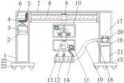
Referring to fig. 1-3, the present invention provides a technical solution: the utility model provides a pond bottom silt cleaning device, including left side frame 1, the bottom of left side frame 1 and right side frame 15 is equal fixedly connected with bottom plate 22, and the bottom fixedly connected with mounting bracket 23 of bottom plate 22, be convenient for install equipment, improve the stability of device, the top fixedly connected with top frame 7 on the right side of left side frame 1, the right side fixedly connected with right side frame 15 of top frame 7, fixedly connected with baffle 2 between the both sides of left side frame 1 inner wall, baffle 2 is convenient for place first motor 3, the top fixedly connected with first motor 3 of baffle 2, first motor 3 is three-phase asynchronous motor, the one end fixedly connected with first conical gear 4 of first motor 3 output shaft, one side meshing of first conical gear 4 has second conical gear 5, the axle center department fixedly connected with pivot 6 of second conical gear 5, the left end and the left side rotation of pivot 6 are connected with the left side of left side frame 1 inner wall, the right end of pivot 6 runs through left side frame 1 and top frame 7 in proper order and extends to the inside of top frame 7, the one end fixedly connected with lead screw 8 in the inside top frame 7, the both ends of lead screw 8 respectively with top frame 7, the both ends of lead screw 8 are connected with top frame 7 inner wall's top block 7 rotation 9, the top block 13 is connected with 13, the top block 13 is connected with the top block 13 of top frame 10 and 13, the top device is connected with the top block 13, the top device is connected with 13 in rotation device is connected with top frame 13, top frame 13 is connected with 13, top frame 13 and bottom 13 is connected with 13, top frame 13 has top 13, top frame 13 and bottom device is connected with top 13, the moving device 10 comprises a moving frame 101, the top of the moving frame 101 is fixedly connected with the bottom of a moving block 9, the bottom of the inner wall of the moving frame 101 is fixedly connected with a second motor 102, one end of an output shaft of the second motor 102 is fixedly connected with a first belt pulley 103, the surface of the first belt pulley 103 is in transmission connection with a second belt pulley 105 through a belt 104, the surface of the second belt pulley 105 is fixedly connected with a cam 106, the axial center of the cam 106 is fixedly connected with the top of the inner wall of the moving frame 101 through a cam seat so as to conveniently stabilize the cam 106, the bottom of the cam 106 is in transmission connection with a moving plate 109, two sides of the bottom of the moving plate 109 are fixedly connected with springs 108, the bottom of the springs 108 is fixedly connected with the bottom of the inner wall of the moving frame 101, the bottom of the moving plate 109 is fixedly connected with a moving rod 107, the bottom of the moving rod 107 penetrates through the moving frame 101 and extends to the outside of the moving frame 101, one end of the moving rod 107 positioned outside the moving frame 101 is fixedly connected with the top of the moving device 11, the moving device 11 comprises an outer frame 111, the top of the outer frame 111 is fixedly connected with the bottom end of the moving rod 107, the bottom of the inner wall of the outer frame 111 is fixedly connected with a third motor 112, one end of the output shaft of the third motor 112 is fixedly connected with a first rotating wheel 113, the surface of the first rotating wheel 113 is connected with a second rotating wheel 115 through a rotating belt 114, the surface of the second rotating wheel 115 is fixedly connected with a rotating disc 116, the surface of the rotating disc 116 is rotationally connected with a push rod 117, the bottom end of the push rod 117 penetrates through the outer frame 111 and extends to the outside of the outer frame 111, one end of the push rod 117 positioned outside the outer frame 111 is rotationally connected with the top of the silt sucking head 13, a transverse plate 16 is fixedly connected between two sides of the inner wall of the right frame 15, the bottom of the inner wall of the right frame 15 is fixedly connected with a silt collecting frame 21, the top of the silt collecting frame 21 is communicated with a silt outlet pipe 20, the top of going out the silt pipe 20 runs through diaphragm 16 and extends to the top of diaphragm 16, and the one end that goes out silt pipe 20 and is located the diaphragm 16 top communicates has and inhales silt pump 17, and the left side intercommunication of inhaling silt pump 17 has into silt pipe 18, and the left end that advances silt pipe 18 runs through right frame 15 and extends to the outside of right frame 15, and the one end that advances silt pipe 18 and is located the outside of right frame 15 communicates there is hose 19, and the one end of hose 19 communicates with one side of inhaling silt head 13.
When the novel electric dredging device is used, the first motor 3 is started to drive the first bevel gear 4 to rotate, the rotating shaft 6 is driven to rotate through the second bevel gear 5, the screw rod 8 is driven to rotate, the moving block 9 is driven to move, the moving device 10 is driven to move, the second motor 102 is driven to rotate, the first belt pulley 103 is driven to rotate through the belt 104, the second belt pulley 105 is driven to rotate, the cam 106 is driven to rotate, the moving plate 109 is driven to move, the moving rod 107 is driven to move, the moving device 11 is driven to move, the third motor 112 is driven to rotate, the second rotating wheel 115 is driven to rotate through the rotating belt 114, the rotating disc 116 is driven to rotate, the push rod 117 is driven to move, the dredging head 13 is driven to move left and right, and meanwhile vibration can be sent, and dredging is convenient to conduct.
It is noted that relational terms such as first and second, and the like are used solely to distinguish one entity or action from another entity or action without necessarily requiring or implying any actual such relationship or order between such entities or actions. Moreover, the terms "comprises," "comprising," or any other variation thereof, are intended to cover a non-exclusive inclusion, such that a process, method, article, or apparatus that comprises a list of elements does not include only those elements but may include other elements not expressly listed or inherent to such process, method, article, or apparatus. Without further limitation. The term "comprising" an element defined by the term "comprising" does not exclude the presence of other identical elements in a process, method, article or apparatus that comprises the element.
Although embodiments of the present invention have been shown and described, it will be understood by those skilled in the art that various changes, modifications, substitutions and alterations can be made therein without departing from the principles and spirit of the invention, the scope of which is defined in the appended claims and their equivalents.
Claims (5)
1. The utility model provides a pond bottom silt cleaning device, includes left frame (1), its characterized in that: the utility model discloses a movable device, including left frame (1), right side, left frame (1), right side fixedly connected with top frame (7), right side fixedly connected with right frame (15) of top frame (7), fixedly connected with baffle (2) between the both sides of left frame (1) inner wall, the top fixedly connected with first motor (3) of baffle (2), the one end fixedly connected with first conical gear (4) of first motor (3) output shaft, one side meshing of first conical gear (4) has second conical gear (5), the axle center department fixedly connected with pivot (6) of second conical gear (5), the left end of pivot (6) rotates with the left side of left frame (1) inner wall to be connected, the right-hand member of pivot (6) runs through left frame (1) and top frame (7) in proper order and extends to the inside of top frame (7), the one end fixedly connected with lead screw (8) of pivot (6) is located the inside top frame (7), the both ends of lead screw (8) rotate with top frame (7) inner wall respectively, the axle center department fixedly connected with pivot (6) and top frame (9) are located outside (9) moving device (10), the bottom of the moving device (10) is fixedly connected with a moving device (11), the bottom of the moving device (11) is fixedly connected with a rotating rod (12), the bottom end of the rotating rod (12) is rotationally connected with a silt sucking head (13), the right side of the top of the silt sucking head (13) is rotationally connected with a stabilizing rod (14), and the top end of the stabilizing rod (14) is rotationally connected with the bottom of the moving device (11);
the mobile device (10) comprises a mobile frame (101), the top of the mobile frame (101) is fixedly connected with the bottom of a mobile block (9), the bottom of the inner wall of the mobile frame (101) is fixedly connected with a second motor (102), one end of an output shaft of the second motor (102) is fixedly connected with a first belt pulley (103), the surface of the first belt pulley (103) is connected with a second belt pulley (105) through a belt (104) transmission, the surface of the second belt pulley (105) is fixedly connected with a cam (106), the axis of the cam (106) is fixedly connected with the top of the inner wall of the mobile frame (101) through a cam seat, the bottom of the cam (106) is in transmission connection with a mobile plate (109), two sides of the bottom of the mobile plate (109) are fixedly connected with springs (108), the bottom of the springs (108) is fixedly connected with the bottom of the inner wall of the mobile frame (101), the bottom of the mobile plate (109) is fixedly connected with a mobile rod (107), the bottom of the mobile rod (107) penetrates the mobile frame (101) and extends to the outside of the mobile frame (101), and is located outside the mobile frame (101);
the motion device (11) comprises an outer frame (111), the top of outer frame (111) is fixedly connected with the bottom of movable rod (107), the bottom fixedly connected with third motor (112) of outer frame (111) inner wall, one end fixedly connected with first runner (113) of third motor (112) output shaft, the surface of first runner (113) is connected with second runner (115) through rotating belt (114) transmission, the surface fixedly connected with carousel (116) of second runner (115), the surface rotation of carousel (116) is connected with push rod (117), the bottom of push rod (117) runs through outer frame (111) and extends to the outside of outer frame (111), push rod (117) are located the outside one end of outer frame (111) and inhale the top rotation connection of silt head (13).
2. The pool bottom sludge cleaning device as claimed in claim 1, wherein: fixedly connected with diaphragm (16) between the both sides of right frame (15) inner wall to the bottom fixedly connected with album of right frame (15) inner wall is to album of silt frame (21), the top intercommunication of album of silt frame (21) has out silt pipe (20), the top of going out silt pipe (20) runs through diaphragm (16) and extends to the top of diaphragm (16), the one end intercommunication that is located diaphragm (16) top of silt pipe (20) has inhale silt pump (17), the left side intercommunication of inhaling silt pump (17) has into silt pipe (18), the outside that right frame (15) and extension to right frame (15) are run through to the left end of advancing silt pipe (18), the one end intercommunication that advances silt pipe (18) and be located the outside of right frame (15) has hose (19), one end and the one side intercommunication of inhaling silt head (13) of hose (19).
3. The pool bottom sludge cleaning device as claimed in claim 2, wherein: the bottoms of the left frame (1) and the right frame (15) are fixedly connected with a bottom plate (22), and the bottom of the bottom plate (22) is fixedly connected with a mounting frame (23).
4. A pool bottom silt cleaning apparatus according to any one of claims 1 to 3, wherein: the top of movable block (9) fixedly connected with slider, the slide rail with slider looks adaptation has been seted up at the top of top frame (7) inner wall.
5. A pool bottom sludge cleaning method is characterized in that: starting a first motor (3) to drive a first bevel gear (4) to rotate, driving a rotating shaft (6) to rotate through a second bevel gear (5), driving a screw rod (8) to rotate, driving a moving block (9) to move, driving a moving device (10) to move, driving a first belt pulley (103) to rotate, driving a second belt pulley (105) to rotate through a belt (104), driving a cam (106) to rotate, driving a moving plate (109) to move, driving a moving rod (107) to move, driving a moving device (11) to move, driving a first rotating wheel (113) to rotate through a rotating belt (114) to drive a second rotating wheel (115) to rotate, driving a rotating disc (116) to rotate, driving a push rod (117) to move, driving a silt sucking head (13) to move left and right and simultaneously moving up and down, and simultaneously sending vibration, so that dredging work is facilitated.
Priority Applications (1)
| Application Number | Priority Date | Filing Date | Title |
|---|---|---|---|
| CN201711008640.7A CN107620334B (en) | 2017-10-25 | 2017-10-25 | Pool bottom sludge cleaning device |
Applications Claiming Priority (1)
| Application Number | Priority Date | Filing Date | Title |
|---|---|---|---|
| CN201711008640.7A CN107620334B (en) | 2017-10-25 | 2017-10-25 | Pool bottom sludge cleaning device |
Publications (2)
| Publication Number | Publication Date |
|---|---|
| CN107620334A CN107620334A (en) | 2018-01-23 |
| CN107620334B true CN107620334B (en) | 2023-06-27 |
Family
ID=61092768
Family Applications (1)
| Application Number | Title | Priority Date | Filing Date |
|---|---|---|---|
| CN201711008640.7A Active CN107620334B (en) | 2017-10-25 | 2017-10-25 | Pool bottom sludge cleaning device |
Country Status (1)
| Country | Link |
|---|---|
| CN (1) | CN107620334B (en) |
Families Citing this family (12)
| Publication number | Priority date | Publication date | Assignee | Title |
|---|---|---|---|---|
| CN108193663B (en) * | 2018-01-24 | 2019-11-19 | 浙江立鹏建设有限公司 | The processing method of foundation stabilization equipment and deep foundation base |
| CN108343104A (en) * | 2018-02-09 | 2018-07-31 | 永春县庆旺食品有限公司 | Food cesspool automatic cleaning apparatus |
| CN108597831B (en) * | 2018-03-22 | 2020-08-14 | 绍兴嘉越纺织机械有限公司 | Glue filling device for electrical mutual inductor |
| CN108612141A (en) * | 2018-05-04 | 2018-10-02 | 芜湖渤江智能科技有限公司 | A kind of quick Accrete clearing device of ship |
| CN110295636A (en) * | 2019-07-16 | 2019-10-01 | 大唐东营发电有限公司 | A kind of thermal power plant's cooling tower pond mud cleaning equipment |
| CN110565716B (en) * | 2019-11-06 | 2020-02-18 | 山东海普欧环保设备科技有限公司 | Sludge cleaning machine |
| CN111042254B (en) * | 2019-12-26 | 2021-10-15 | 陕西理工大学 | Riverway dredging sandglass device |
| CN111549843B (en) * | 2020-05-16 | 2022-02-11 | 广东省福日升绿色科技研究有限公司 | Automatic sludge garbage treatment process |
| CN113062386A (en) * | 2021-03-02 | 2021-07-02 | 汪波 | Effectual river course desilting device of anticollision for hydraulic engineering |
| CN113605480B (en) * | 2021-09-16 | 2022-11-15 | 李炳辰 | Hydraulic engineering is with quick silt clearing device |
| CN114293614B (en) * | 2022-01-10 | 2023-02-17 | 浙江丰茂盛业建设有限公司 | Novel river sludge comprehensive treatment ecological restoration device and construction method thereof |
| CN115517221B (en) * | 2022-10-10 | 2023-09-22 | 烟台市海洋经济研究院(烟台市渔业技术推广站、烟台市海洋捕捞增殖管理站) | Impurity cleaning device for sea cucumber industrial culture |
Citations (12)
| Publication number | Priority date | Publication date | Assignee | Title |
|---|---|---|---|---|
| JPS63138027A (en) * | 1986-11-29 | 1988-06-10 | Murazumi Kensetsu Kk | Dredging method |
| CN2703037Y (en) * | 2004-05-13 | 2005-06-01 | 喻国良 | Sludge suction and cleaning dredger |
| CN202031115U (en) * | 2011-04-22 | 2011-11-09 | 吴德万 | Automatic desilter for water bottom |
| EP2586962A1 (en) * | 2011-10-24 | 2013-05-01 | Soilmec S.p.A. | System for evacuating sludge for a trench excavating machine |
| CN204510312U (en) * | 2015-01-15 | 2015-07-29 | 杭州华能大坝安全工程技术有限公司 | A kind of mud-sucking device being applied to underwater desilting |
| CN204510317U (en) * | 2015-03-24 | 2015-07-29 | 杭州沐阳建筑技术有限公司 | A kind of mud-sucking device being under water applied to ecological riverway |
| CN205676950U (en) * | 2016-06-13 | 2016-11-09 | 武平泓鑫工业技术开发有限公司 | A kind of Pond Silt removes device |
| CN205975761U (en) * | 2016-08-23 | 2017-02-22 | 江西容大水利水电建设工程有限公司 | Last dedicated sediment removal device of water conservancy construction |
| CN206052823U (en) * | 2016-08-18 | 2017-03-29 | 李燕 | A kind of mobile stirring-type mud desilting segregation apparatuss |
| CN206110215U (en) * | 2016-08-24 | 2017-04-19 | 浙江义海航道工程有限公司 | Hydraulic suction dredge with pine mud function |
| CN206233286U (en) * | 2016-12-08 | 2017-06-09 | 河南省驻马店水文水资源勘测局 | Water conservancy construction Accrete clearing device |
| CN207553186U (en) * | 2017-10-25 | 2018-06-29 | 浙江两山信息科技有限公司 | A kind of bottom of pond silt cleaning device |
-
2017
- 2017-10-25 CN CN201711008640.7A patent/CN107620334B/en active Active
Patent Citations (12)
| Publication number | Priority date | Publication date | Assignee | Title |
|---|---|---|---|---|
| JPS63138027A (en) * | 1986-11-29 | 1988-06-10 | Murazumi Kensetsu Kk | Dredging method |
| CN2703037Y (en) * | 2004-05-13 | 2005-06-01 | 喻国良 | Sludge suction and cleaning dredger |
| CN202031115U (en) * | 2011-04-22 | 2011-11-09 | 吴德万 | Automatic desilter for water bottom |
| EP2586962A1 (en) * | 2011-10-24 | 2013-05-01 | Soilmec S.p.A. | System for evacuating sludge for a trench excavating machine |
| CN204510312U (en) * | 2015-01-15 | 2015-07-29 | 杭州华能大坝安全工程技术有限公司 | A kind of mud-sucking device being applied to underwater desilting |
| CN204510317U (en) * | 2015-03-24 | 2015-07-29 | 杭州沐阳建筑技术有限公司 | A kind of mud-sucking device being under water applied to ecological riverway |
| CN205676950U (en) * | 2016-06-13 | 2016-11-09 | 武平泓鑫工业技术开发有限公司 | A kind of Pond Silt removes device |
| CN206052823U (en) * | 2016-08-18 | 2017-03-29 | 李燕 | A kind of mobile stirring-type mud desilting segregation apparatuss |
| CN205975761U (en) * | 2016-08-23 | 2017-02-22 | 江西容大水利水电建设工程有限公司 | Last dedicated sediment removal device of water conservancy construction |
| CN206110215U (en) * | 2016-08-24 | 2017-04-19 | 浙江义海航道工程有限公司 | Hydraulic suction dredge with pine mud function |
| CN206233286U (en) * | 2016-12-08 | 2017-06-09 | 河南省驻马店水文水资源勘测局 | Water conservancy construction Accrete clearing device |
| CN207553186U (en) * | 2017-10-25 | 2018-06-29 | 浙江两山信息科技有限公司 | A kind of bottom of pond silt cleaning device |
Also Published As
| Publication number | Publication date |
|---|---|
| CN107620334A (en) | 2018-01-23 |
Similar Documents
| Publication | Publication Date | Title |
|---|---|---|
| CN107620334B (en) | Pool bottom sludge cleaning device | |
| CN107055674A (en) | A kind of sewage quick treatment device for building | |
| CN206715393U (en) | A kind of chain transmission type second pond mud-scraping apparatus for sewage disposal | |
| CN108128920B (en) | Sewage filtering device | |
| CN110127887A (en) | A kind of sewage treatment settling apparatus | |
| CN215505924U (en) | Industrial wastewater sedimentation tank capable of dredging | |
| CN110898477A (en) | Sludge discharge device for sewage treatment | |
| WO2019242080A1 (en) | Chemical plant sewage processing and purifying apparatus | |
| CN211447233U (en) | Novel dredging device for hydraulic engineering | |
| CN108499748A (en) | A kind of oil field welldrilling coarse sand granule filter device | |
| CN206014525U (en) | A kind of exhausting or trade effluent advanced treatment apparatus | |
| CN210528868U (en) | Anti-blocking filter device for oil extraction in oil field | |
| CN209413874U (en) | A kind of oil drilling slurry processing unit | |
| CN208660539U (en) | A kind of environment protection sewage processing equipment that vibrating effect is good | |
| CN210583828U (en) | Hydraulic reciprocating mud scraper | |
| CN207694419U (en) | A kind of efficient vertical sloping plate deposition machine | |
| CN207192979U (en) | A kind of poultry farming waste water quality high-level cleaner | |
| CN110917718A (en) | Energy-saving and environment-friendly urban sewage treatment recycling device | |
| CN216023510U (en) | Wastewater treatment device for ecological agriculture construction | |
| CN110127813A (en) | A kind for the treatment of tank sludge removal | |
| CN218330782U (en) | Sampling device that municipal administration sewage treatment used | |
| CN209575994U (en) | A kind of high efficiency sewage treatment facility with damping | |
| CN218405775U (en) | Municipal administration is dredging device for sewage pipe | |
| CN219091206U (en) | Sewage pretreatment reaction device convenient for cleaning sediment | |
| CN208611862U (en) | A kind of water factory's Novel water-purifying settler |
Legal Events
| Date | Code | Title | Description |
|---|---|---|---|
| PB01 | Publication | ||
| PB01 | Publication | ||
| SE01 | Entry into force of request for substantive examination | ||
| SE01 | Entry into force of request for substantive examination | ||
| TA01 | Transfer of patent application right |
Effective date of registration: 20230606 Address after: 2/F, Building 1, Xincheng Science and Technology Park, No. 69 Aoti Street, Jianye District, Nanjing City, Jiangsu Province, 210000 Applicant after: Chuangye Heima (Jiangsu) Technology Co.,Ltd. Address before: 313300 Sunshine Industrial Park, Dipu Street, Anji County, Huzhou City, Zhejiang Province, 4 buildings and 2 floors Applicant before: ZHEJIANG LIANGSHAN INFORMATION TECHNOLOGY CO.,LTD. |
|
| TA01 | Transfer of patent application right | ||
| GR01 | Patent grant | ||
| GR01 | Patent grant |