CN1075656C - Integral hub and disk clamp for a disk drive storage device - Google Patents
Integral hub and disk clamp for a disk drive storage device Download PDFInfo
- Publication number
- CN1075656C CN1075656C CN95105030A CN95105030A CN1075656C CN 1075656 C CN1075656 C CN 1075656C CN 95105030 A CN95105030 A CN 95105030A CN 95105030 A CN95105030 A CN 95105030A CN 1075656 C CN1075656 C CN 1075656C
- Authority
- CN
- China
- Prior art keywords
- dish
- disk
- storage device
- data storage
- rotating disc
- Prior art date
- Legal status (The legal status is an assumption and is not a legal conclusion. Google has not performed a legal analysis and makes no representation as to the accuracy of the status listed.)
- Expired - Fee Related
Links
- 239000000463 material Substances 0.000 claims description 19
- 210000000078 claw Anatomy 0.000 claims description 15
- 238000013500 data storage Methods 0.000 claims description 15
- 229920000642 polymer Polymers 0.000 claims description 3
- 238000001746 injection moulding Methods 0.000 claims 1
- 231100000572 poisoning Toxicity 0.000 claims 1
- 230000000607 poisoning effect Effects 0.000 claims 1
- XEEYBQQBJWHFJM-UHFFFAOYSA-N Iron Chemical compound [Fe] XEEYBQQBJWHFJM-UHFFFAOYSA-N 0.000 abstract description 30
- 229910052742 iron Inorganic materials 0.000 abstract description 14
- 239000002991 molded plastic Substances 0.000 abstract 1
- 230000005055 memory storage Effects 0.000 description 9
- 239000004411 aluminium Substances 0.000 description 4
- XAGFODPZIPBFFR-UHFFFAOYSA-N aluminium Chemical group [Al] XAGFODPZIPBFFR-UHFFFAOYSA-N 0.000 description 4
- 229910052782 aluminium Inorganic materials 0.000 description 4
- 238000005516 engineering process Methods 0.000 description 4
- 239000010410 layer Substances 0.000 description 4
- 238000000465 moulding Methods 0.000 description 4
- 230000035939 shock Effects 0.000 description 4
- 239000007787 solid Substances 0.000 description 4
- 239000000758 substrate Substances 0.000 description 4
- 230000008859 change Effects 0.000 description 3
- 239000004697 Polyetherimide Substances 0.000 description 2
- 229910000831 Steel Inorganic materials 0.000 description 2
- 239000007767 bonding agent Substances 0.000 description 2
- 230000000694 effects Effects 0.000 description 2
- 230000002708 enhancing effect Effects 0.000 description 2
- 230000006870 function Effects 0.000 description 2
- 230000006872 improvement Effects 0.000 description 2
- 239000007788 liquid Substances 0.000 description 2
- 229910052751 metal Inorganic materials 0.000 description 2
- 239000002184 metal Substances 0.000 description 2
- 229920001601 polyetherimide Polymers 0.000 description 2
- 238000003825 pressing Methods 0.000 description 2
- 238000010107 reaction injection moulding Methods 0.000 description 2
- 230000003068 static effect Effects 0.000 description 2
- 239000010959 steel Substances 0.000 description 2
- 241000446313 Lamella Species 0.000 description 1
- 229910000978 Pb alloy Inorganic materials 0.000 description 1
- UVTGXFAWNQTDBG-UHFFFAOYSA-N [Fe].[Pb] Chemical compound [Fe].[Pb] UVTGXFAWNQTDBG-UHFFFAOYSA-N 0.000 description 1
- 238000005452 bending Methods 0.000 description 1
- 230000000903 blocking effect Effects 0.000 description 1
- 230000021615 conjugation Effects 0.000 description 1
- 238000005530 etching Methods 0.000 description 1
- 239000011521 glass Substances 0.000 description 1
- 150000002466 imines Chemical class 0.000 description 1
- 238000002347 injection Methods 0.000 description 1
- 239000007924 injection Substances 0.000 description 1
- 238000009434 installation Methods 0.000 description 1
- 238000003754 machining Methods 0.000 description 1
- 239000000696 magnetic material Substances 0.000 description 1
- 230000005415 magnetization Effects 0.000 description 1
- 238000004519 manufacturing process Methods 0.000 description 1
- 230000007246 mechanism Effects 0.000 description 1
- 238000000034 method Methods 0.000 description 1
- 230000035699 permeability Effects 0.000 description 1
- 239000004033 plastic Substances 0.000 description 1
- 229920003023 plastic Polymers 0.000 description 1
- 229920000570 polyether Polymers 0.000 description 1
- -1 pottery Substances 0.000 description 1
- 239000011241 protective layer Substances 0.000 description 1
- 230000009467 reduction Effects 0.000 description 1
- 239000012858 resilient material Substances 0.000 description 1
- 238000007789 sealing Methods 0.000 description 1
- 239000004065 semiconductor Substances 0.000 description 1
- 238000009987 spinning Methods 0.000 description 1
- 239000000126 substance Substances 0.000 description 1
- 238000010998 test method Methods 0.000 description 1
- XLYOFNOQVPJJNP-UHFFFAOYSA-N water Substances O XLYOFNOQVPJJNP-UHFFFAOYSA-N 0.000 description 1
Images


Classifications
-
- G—PHYSICS
- G11—INFORMATION STORAGE
- G11B—INFORMATION STORAGE BASED ON RELATIVE MOVEMENT BETWEEN RECORD CARRIER AND TRANSDUCER
- G11B17/00—Guiding record carriers not specifically of filamentary or web form, or of supports therefor
- G11B17/02—Details
- G11B17/022—Positioning or locking of single discs
- G11B17/028—Positioning or locking of single discs of discs rotating during transducing operation
- G11B17/0282—Positioning or locking of single discs of discs rotating during transducing operation by means provided on the turntable
-
- G—PHYSICS
- G11—INFORMATION STORAGE
- G11B—INFORMATION STORAGE BASED ON RELATIVE MOVEMENT BETWEEN RECORD CARRIER AND TRANSDUCER
- G11B17/00—Guiding record carriers not specifically of filamentary or web form, or of supports therefor
- G11B17/02—Details
-
- G—PHYSICS
- G11—INFORMATION STORAGE
- G11B—INFORMATION STORAGE BASED ON RELATIVE MOVEMENT BETWEEN RECORD CARRIER AND TRANSDUCER
- G11B17/00—Guiding record carriers not specifically of filamentary or web form, or of supports therefor
- G11B17/02—Details
- G11B17/022—Positioning or locking of single discs
- G11B17/028—Positioning or locking of single discs of discs rotating during transducing operation
- G11B17/0287—Positioning or locking of single discs of discs rotating during transducing operation by permanent connections, e.g. screws, rivets
-
- G—PHYSICS
- G11—INFORMATION STORAGE
- G11B—INFORMATION STORAGE BASED ON RELATIVE MOVEMENT BETWEEN RECORD CARRIER AND TRANSDUCER
- G11B17/00—Guiding record carriers not specifically of filamentary or web form, or of supports therefor
- G11B17/02—Details
- G11B17/038—Centering or locking of a plurality of discs in a single cartridge
-
- G—PHYSICS
- G11—INFORMATION STORAGE
- G11B—INFORMATION STORAGE BASED ON RELATIVE MOVEMENT BETWEEN RECORD CARRIER AND TRANSDUCER
- G11B25/00—Apparatus characterised by the shape of record carrier employed but not specific to the method of recording or reproducing, e.g. dictating apparatus; Combinations of such apparatus
- G11B25/04—Apparatus characterised by the shape of record carrier employed but not specific to the method of recording or reproducing, e.g. dictating apparatus; Combinations of such apparatus using flat record carriers, e.g. disc, card
- G11B25/043—Apparatus characterised by the shape of record carrier employed but not specific to the method of recording or reproducing, e.g. dictating apparatus; Combinations of such apparatus using flat record carriers, e.g. disc, card using rotating discs
Landscapes
- Holding Or Fastening Of Disk On Rotational Shaft (AREA)
- Rotational Drive Of Disk (AREA)
- Automatic Disk Changers (AREA)
- Apparatus For Radiation Diagnosis (AREA)
- Signal Processing For Digital Recording And Reproducing (AREA)
- Friction Gearing (AREA)
- Feeding And Guiding Record Carriers (AREA)
Abstract
A disk drive contains an integrally-formed one-piece hub, clamp and rotor housing, which is preferably injection-molded plastic. In the preferred embodiment, the hub includes a hollow cylindrical portion and a flange portion. During assembly, the disk is forced over the pawls of the fingers until they engage the disk. The fingers, being slightly elastic, will deform to permit the disk to slide over the pawls, and then return to lock the disk in place. The fingers automatically center the disk about the hub axis, without the need for centering tools. The hub also serves as a housing for the rotor of a spindle motor which rotates the disk. An electromagnetic stator assembly surrounds the disk axis in the annular space defined by the flange, the permanent magnets and back iron at the outer edge, and the cylindrical portion of the hub at the inner edge.
Description
The present invention relates to disk drive data storage device, relate in particular to the dish and the propeller boss assembly that are used for the disk drive memory storage.
The mass data storage of modem computer systems needs to require to have the high capacity mass data storage.General memory storage is the spinning disk driver.
Disk drive generally includes one or more pieces rigidity and is installed to smooth, flat dish on the public axle.Dish is stacked on the axle in parallel with each other, and is separated out, and makes them not contact.By spindle motor, dish rotates with constant speed with axle.
Each dish is made by the solid substrate or the egative film of a slice disk shape, and individual axis hole is arranged in the centre.Though glass, pottery, plastics or other material are feasible, substrate is aluminium normally.Cover the thin magnetisable material of one deck on the substrate, and can add layer protective layer.
Data are recorded on the magnetizable layer of panel surface.For this reason, the small magnetization pattern of expression data forms in magnetizable layer.Data pattern (pattern) is usually placed in the concentric circular track.Each road further is divided into some sectors.Like this, each sector is in the arc-shaped, and all sectors in road form a circle.
One movably the actuator position sensor head make it data near panel surface to read or write data.This actuator may resemble the tone arm of electric phonograph, and head then resembles stylus.
Each panel surface that has data has a sensor head.This sensor head is the block that magnetic read/write sensor was made, was equipped with on it to an aerodynamic force shape, certain material (pottery usually).When disc spins, this block, or slide block moves down at distance card point blank place.Apart from this very near distance of panel surface for sensor being read or write-ining data mode is vital in magnetizable layer.Can adopt several different designs, and in some cases, read transducer separates with writing sensor.
Actuator is that positioning head is rotated in the center with an axle usually.It generally includes: near the solid block rotating shaft, this rotating shaft have the pectination arm that stretches to dish.One cover installs to the slim cantilever on the arm; With a electromagnetic machine in the opposite side of this rotating shaft.Sensor head installs on the cantilever, cantilever one stature.Actuator motor is rotated this actuator so that head is positioned on the desired data road.In case head is positioned the top, the constant speed rotation of dish will finally make required sector next-door neighbour's head, so just readable or write data.
Along with computer system becomes with better function, faster and more reliable, to corresponding increase of demand of improved memory storage.Several modes have been taked in these desirable improvement.Hope reduces cost, and increases the data reserves, accelerates drive operation speed, reduces driver institute consuming electric power, and strengthens the restorability of driver under physical shock or other interference.
Particularly, wish to dwindle the physical size of disk drive.To a certain extent, size is dwindled the effect that can play further some above-mentioned targets of realization.But meanwhile, the disk drive size to reduce with regard to himself also be desirable.Size is dwindled to make in removable range of application (for example, laptop computer, mobile paging machine and " smart card "), and to use disk drive be feasible.
The example that size is dwindled be the second class PCMCIA Type II standard application to disk drive.This standard original plan is used for semiconductor package.But,, just may produce the disk drive that meets PCMCIA Type II standard along with the improvement of miniaturization technologies.
In order to reduce the size of disk drive, each element all must reduce size as much as possible.In addition, the new design that must develop existing element reduces size and must make the assembling of microminiaturized element feasible allowing.
A restriction of disk drive reduced size degree is a dish/propeller boss assembly.Conventional dish/propeller boss assembly comprises a cylindrical propeller boss, and a flange that is used for the support disc group is arranged at its bottom.The motor that is used for rotating disc places among the propeller boss.The dish group remains on lug upper surface, and propeller boss is installed in the corresponding dish hole.Between every dish by around and near the gasket ring of propeller boss separately.Clamp device is contained on the propeller boss top, and applies downward acting force to the dish group, thereby makes the dish of bottom be pressed onto on the flange and the dish group is remained on the appropriate location.When disk drive has only a slice dish, adopt essentially identical design, but clamp device only clamps a slice dish, rather than the dish group.Clamp device is a flat steel loop normally, near its neighboring one circular ridge that is shaped is arranged.The flat part of ring is screwed in the top of propeller boss with screw, exerts pressure to dish group or monolithic dish with the convex ridge part.Have several selective jig Design, but all designs all comprise a plurality of parts.
The design of conventional disk drive dish/propeller boss is not fit to well that the very disk of Small Form Factor is arranged, for example PCMCIA Type II shape coefficient.Propeller boss must be enough greatly to load screw.Even use very little screw, this requirement has also increased the size and the weight of propeller boss.Too little parts make the assembling difficulty, and, also have any problem when in removable application, bearing high physical shock.When going to press from both sides with excessive folder power, the dish of relative thin is flexible; When the road width reduces, even little bending also is serious.At last, even driver is less, the simple ratio of legacy device is dwindled can not produce any significant cost reduction yet.In fact, this may increase cost.Wish exploitation a kind of selective propeller boss/dish assembly, it can reduce cost and be more suitable for the designing requirement of Small Form Factor disk drive.
Therefore, first purpose of the present invention provides a kind of disk drive memory storage of enhancing.
Another object of the present invention is to reduce the cost of disk drive memory storage.
Another object of the present invention provides a kind of propeller boss/dish assembly that is used for the enhancing of Small Form Factor disk drive memory storage.
Another object of the present invention provides propeller boss/disk pack unit that a kind of cost that is used for Small Form Factor disk drive memory storage reduces.
Another object of the present invention provides a kind of propeller boss/dish assembly that less parts is arranged.
Another object of the present invention provides a kind of propeller boss/dish assembly that is easy to make and install.
Another object of the present invention provides a kind of propeller boss/dish assembly that bigger anti-physical shock is arranged.
Another object of the present invention provides a kind of propeller boss/dish assembly that reduces dish distortion possibility.
The dish of disk drive is contained on integrally formed integral hub, jig and the rotor case.Propeller boss is preferably by injection molded.In preferred forms, propeller boss comprises: the column part of hollow basically, and it is used to surround and is contained in the cover of one on central mast bearing; And outwardly directed flange portion of column part from close right cylinder middle part.This flange support is lived a monolithic dish that is placed on its upper surface.A plurality ofly protrude upward, to block dish by center hole at the upper surface of circumferencial direction flexibility card hand placed apart from flange.Hand is little leans outward for card, and does not hold at each card hand and to comprise that a claw is to block dish.The periphery of dish mesopore preferably is cut into the inclined-plane, is positioned at central authorities to improve with the conjugation of card hand and with dish.For dish is installed on the propeller boss, will coil simply with the claw of defeating the card hand, up to being stuck with hypotenuse.Have flexible card hand and will curve inwardly and slip over claw, will outwards restore subsequently so that dish is locked in the appropriate location with the permission dish.Need not the centralized positioning device, the card hand is positioned at disk center the axis of propeller boss automatically.
Propeller boss also is used as the rotor case of the spindle motor of rotating disc.In preferred forms, brshless DC motor is contained in below the flange.Break iron ring (back iron ring) and permanent magnet are contained in below the neighboring of flange to form the rotor part.Around the dish axle, permanent magnet and break iron ring are in its outside in by the annular space of flange limit for the electromagnetic stator assembly, and the column part of propeller boss is in its inside.
Fig. 1 is the disc driver memory storage according to preferred forms.
Fig. 2 is the isometric drawing of integral hub, jig and rotor case according to preferred forms.
Fig. 3 is the cut-open view of integral hub, jig and rotor case according to preferred forms.
Fig. 4 is according to the vertical view that can select integral hub, jig and the rotor case of embodiment.
Fig. 5 partly cuts open figure according to the propeller boss of preferred forms and dish assembly.
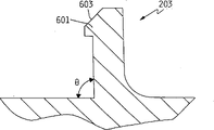
Fig. 6 is the cut-open view of the card hand portion of integral hub, jig and rotor case according to preferred forms.
Fig. 7 is the cut-open view according to the card hand of preferred forms, the figure illustrates this card hand and how dish is clamped in the appropriate location.
Fig. 8 is the cut-open view of a card hand and an alternative design of disk.
Fig. 1 has shown the disc driver memory device 100 according to preferred forms.Disk unit 100 comprises that a rigidity is contained in the rotatable disk 101 of propeller boss 103, and this propeller boss is contained on disc driver base or the shell 104.Propeller boss 103 is driven with constant rotational speed by the driver motor with disk 101.The driver motor is included in the propeller boss 103.Actuator 105 is positioned at the one side of disk 101.Actuator 105 is driven by electromagnetic machine 107, is rotating with the alignment sensor head in the arc scope of the bar 106 that is parallel to disk 101 axis.A lid (not shown) cooperates with base 104 to surround and protection disk and actuator.The electronic module that is used to control disk operating and communicates by letter with miscellaneous equipment (as main frame) is contained in the circuit card 112 in the Magnetic Head shell that base 104 and lid surround.In this embodiment, circuit card 112 is contained in this shell and forms the shape of utilizing unappropriated space around the disk, saving the space, as in order to be suitable for PCMCIA Type II shape coefficient being used.But card 112 also can be contained in the outside of Magnetic Head shell, and perhaps, base itself also can be made circuit card so that electronic module is directly installed to above it.A plurality of magnetic head/slider assembly 108 rigidity are contained on the arm of actuator.Aerodynamic force read/write transducers head 109 is positioned at the end of each magnetic head/slider assembly 108 of next-door neighbour's magnetic disk surface.
Fig. 2 is the isometric drawing of integral hub, jig and rotor case 103 according to preferred forms.Propeller boss 103 comprises best: 201, one of the cylindrical essential parts of a hollow from essential part 201 stretch out, flat relatively cylindrical flange part 202 and a plurality ofly block disk 101 and as the card hand 203 of clamp device along circumferentially separating, being used to.
Fig. 3 is integral hub, jig and the cut-open view of rotor case 103 on the disk spindle plane according to preferred forms.Can see clearlyer from the cut-open view of Fig. 3, the cylindrical essential part 2d of hollow has defined one and has been positioned at cylindrical hole 301 center, that be used for disk roofbolt and bearing.Flange portion 202 stretches out from the middle part of about essential part 201.Circumference heel teeth 302 stretches out downwards from the lower surface of flange 202 near its neighboring.Heel teeth 302 provides a faying face and has been used for the support of rotor break iron and permanent magnet.
Fig. 4 is the vertical view of integral hub, jig and rotor case 103 according to preferred forms.In preferred forms, propeller boss 103 comprises 8 card hands 203 that equidistantly distribute as shown in the figure.The number and the size that are appreciated that the card hand can change, and can use other monoblock type clamp device in spirit of the present invention and scope.
Fig. 5 shows propeller boss 103 and the related hardware according to preferred forms in greater detail, the spindle motor element when comprising assembling.Fig. 5 be the disk spindle plane partly cut open figure.Although in Fig. 5, only drawn at axle propeller boss 103 and related hardware on one side, should understand that they are with rotational symmetry.
The flange portion 202 of propeller boss 103 middle protruding on cylindrical essential part 201, in about its length.Disk 101 is placed on the upper surface of flange 202, and flange supports disk 101 from below.A plurality of same circumference card hand 203 at interval protrudes upward to block disk and it is locked in the appropriate location from the upper surface of flange 202, like this as clamp device and avoided be assembled into the demand of jig by discrete component.
The break iron 505 and permanent rotor magnet 506 external members that are used for the brushless direct-current spindle motor are contained in below flange portion 202 neighborings.Break iron 505 is annulus of a permeability magnetic material, preferred iron-lead alloy.The also many lamellas of break iron 505 twist in together and the annulus that forms.Magnet 506 is the solid iron hoop of suitable magnetisable material preferably, and wherein, continuous arc piece section is magnetized to the magnetic pole of alternation.So magnet 506 has formed one group of permanent arc-shaped magnet, it is arranged along circumference around disk axis with this axle of complete encirclement, and has alternating polarity.
Circumference heel teeth 302 provides the support to break iron 505 and magnet 506.Break iron 505 has used suitable best bonding agent, in the lower surface bonds of heel teeth 32 places and flange 202 to propeller boss 103.Alternatively, in the reaction-injection moulding process,, like this break iron is linked on the propeller boss by break iron 505 being put into die cavity molding propeller boss 103 on break iron 505 then.Permanent magnet 506 uses suitable bonding agent directly to bond to break iron 505 best.
Spindle motor electromagnetic stator 508 installs to base 104, places below the flange 202, and is in internal diameter and is defined by cylindrical essential part 201, in the annular space that external diameter is defined by break iron 505 and magnet 506.Stator 508 comprises one group around the separated electromagnet of disk axis circumference (utmost point), and each utmost point comprises a coil that twines around the magnetic conduction heart.Stator 508 links to each other with motor-driven electronic circuit (not shown) on the circuit board 112.As described in the present technique field, in operation, the motor-driven electronic circuit sends pulse to produce a rotating magnetic field to the different poles of stator 508 continuously.In preferred forms, stator 508 is threephase stators, and each has 3 utmost points (totally 9 utmost points) mutually, and rotor magnet group 506 comprises 12 magnetic segmental arcs.But the number of rotor and stator poles can change.
Fig. 6 is the cut-open view that card hand 203 is crossed the disk axis plane, and it shows this card hand in greater detail.Card hand 203 is molded as and littlely outward-dippingly applies slight radial force with the endoporus to disk 101.The inclination angle is 3 degree preferably approximately, and promptly the angle θ among Fig. 6 is near 87 degree.Be appreciated that best angle changes with the thickness and the selected materials type of card hand.End near card hand 203 is the claw 601 that is used to block disk 101.Claw 601 comprises that one is cut oblique top margin 603 so that disk can be installed.
Fig. 7 is the sectional view of card hand 203, has shown how it is stuck in the appropriate location with disk 101.Disk 101 and the cross-sectional view of card hand 203 in the plane of crossing disk axis have also drawn.
On hand and directly make disk 101 be installed to propeller boss 103 best to be taken in when pressing down to pressing down by disk 101 being navigated to card, the hypotenuse 712 of disk 101 bottom surfaces slides against the hypotenuse 603 of claw 601 upper surfaces.Because card hand 203 is made by resilient material, when disk 101 is pressed downwardly onto it, bends in the card hand 203 (to disk axis), thereby make the narrow position of Kongzui, disk center cross claw.After claw was crossed at the narrow position of Kongzui, disk center, because the natural elasticity of material, the card hand returned near its original position.When the disk bottom surface was put on the flange 202, claw 601 was placed with as shown in Figure 7, and hypotenuse 711 is applied a power.
601 pairs of hypotenuses 711 of claw had both applied a downward axial force, also applied a radial force.Downward axial force is pushed against the upper surface of flange portion 202 with disk 101, tightly disk 101 is stuck in the appropriate location.
Because a plurality of card hands of separate placing along circumference on distance disk axis same radius have applied identical radial force to the oblique inner edge 711 of disk center pit, therefore when disk was firmly moved past the card hand and enter installation site on flange, disk was automatically positioned on the center of rotating shaft.Like this, just need not the centralized positioning instrument.
In the test of falling, find that flexible card hand has absorbed the most of energy that passes to propeller boss 1-3 from disk 101, has therefore prevented the infringement to bearing arrangement.This feature is very desirable for the portable media technology.
The warpage of disk is a problem known in the disk drive technologies.Conventional jig must not move to guarantee disk imposed sizable axial force by the disk of mounting board.This power tends to make the disk warpage.Observed flexible clip mechanism for card of the present invention and obtained, and do not had warpage substantially the firm mounting board of disk.Unlike the conventional jig design of usually using the metal mounting board, propeller boss of the present invention uses much softer that flexible material is made than disk itself best.The surface of flexible material (is the upper surface and the card hand (203) of flange portion 202 in the contact point place distortion with disk.This provides the much bigger static friction coefficient of static friction coefficient that is produced than metal-metal contact in the conventional disk jig.Because higher coefficient of friction uses less axial force, disk just can be clamped.In addition, because disc material is much harder than the propeller boss material, propeller boss surface rather than magnetic disk surface are out of shape at contact point.Therefore, near inner radius, disk stands very little local tension force, and consequently, comparing with conventional disk has very little warpage.
Must when being in correct position, disk provide enough clamping forces simultaneously according to the size of selected disc material selection card hand 203 so that suitable card hand biddability to be provided.In preferred forms, it is wide that card hand 203 radial dimensions are about 0.25mm, and circumferencial direction 1mm is wide.The about 1mm of height overall of card hand.Those skilled in the art are appreciated that best card hand size changes according to material quality.Harder propeller boss material may need thin card hand, and vice versa.And can understand size also according to the size of disk itself and material and change.Above-mentionedly be intended to be used for a kind of 1.8 inches disks for the given size of preferred forms, this dish is made of the thick aluminium matter substrate of about 0.635mm, as is used for the PCMCIA Type II shape coefficient.
Fig. 8 clamps card hand 801 and disk one can select the sectional view that designs.Remove and added outside the projection 802 of stretching out on hand from the card towards disk axis, the selective clamping card hand 801 among Fig. 8 is with above-mentioned and the same at the clamping card hand 203 shown in Fig. 1-7.Projection 802 provides one to be used for removing the surface that the instrument (not shown) cooperates with disk.In order to remove disk 101, this instrument applies a downward power to projection 802, is easy to like this card hand 801 to palintrope.Meanwhile, disk 101 is removed from the flange portion of propeller boss 103.When disc driver at duration of work again as the Computer-Assisted Design, Manufacture And Test procedure division, removing of disk is necessary sometimes.
In preferred forms, clamping device is a plurality of card hands that stretch out and block disk from lug upper surface.But, in spirit of the present invention and scope, can use any and the integrally formed clamping device of propeller boss.For example, the card hand can stretch out from the other parts (as the cylindrical essential part 201 of hollow) of propeller boss.Can press disk from the top down from the card hand that some other place (as cylindrical part) stretches out.Alternatively be, the mounting board instrument can be one from lug upper surface or the deformable loop that stretches out from the barrel portion of hollow, perhaps deformable loop that disconnects at certain intervals at circumferencial direction, this ring is used for stress relieving.
In the above description, some features are censured to flange " above " or " below ", and the surface be described as " on " or D score.Use these terms only to be used for censuring convenient and choose consistent with used pattern and the conventional direction of technology.But, use these terms and do not mean that to show that the present invention needs flange to be positioned under the disk and on the motor.Flange is positioned at above the disk, or motor is changeed the flat orientation of drawing water, disk of the present invention and motor are easy to structure too.
Even disclose a specific embodiment of the present invention and some selectable schemes, those skilled in the art can recognize other variation that can obtain shape and details in following claim scope.
Claims (12)
1. rotating disc data storage device comprises:
A disk drive base;
One is used for record data and rotatably mounted dish, and described dish has a rotating shaft and first and second surfaces vertical with described rotating shaft, and a manhole that is positioned at its center is arranged;
A rotatable propeller boss that is used to install described dish;
One is used for the mounting board structure of described dish mounting board to the described rotatable propeller boss, described mounting board structure comprises a contacted supporting surface of described first surface with described rotatably mounted dish, and a plurality of card hands of placing of separating along circumference, each described card hand has a claw at the one end, described card hand extends through the described manhole of described dish, described claw blocks dish and described dish is applied an axial force, and the described first surface of described dish is pressed against described supporting surface;
A spindle motor that is used to rotate described dish;
At least one is used to read the sensor head of described disk storage data; And
One is contained in described disk drive base and is used to locate described sensor head to read the actuator of described dish record data.
2. according to the rotating disc data storage device of claim 1, it is characterized in that: the described through hole of described dish has formed an inside surface around described rotating shaft, and described card hand contacts with described inside surface, thereby each card hand applies a radial force to described dish.
3. according to the rotating disc data storage device of claim 2, it is characterized in that: claw blocks described dish along the hypotenuse around described manhole.
4. according to the rotating disc data storage device of claim 1, it is characterized in that: each described claw comprises that one is used for removing the projection that instrument cooperates with dish, and described projection is from giving prominence to towards described one side of coiling the described card hand of axle.
5. according to the rotating disc data storage device of claim 1, it is characterized in that: described supporting surface and described card hand are made by a kind of flexible material, and described flexible material has more biddability than described dish.
6. according to the rotating disc data storage device of claim 1, it is characterized in that: described clip structure also comprises the rotor case that is used to hold the spindle motor rotor;
The rotor magnet of described spindle motor is installed in the described rotor case; And
The stator of described spindle motor is installed on the described base.
7. according to the rotating disc data storage device of claim 6, it is characterized in that: described clip structure comprises:
Have the cylindrical part of the hollow of the axle that a described rotating shaft with described dish coincides, the cylindrical part of described hollow encases the dish axostylus axostyle and is installed in the described manhole of described dish; And
From the protruding flange portion of the cylindrical part of described hollow, described a plurality of card hands stretch out from described flange portion.
8. according to the rotating disc data storage device of claim 7, it is characterized in that: the cylindrical part of described hollow surrounds a bearing that is used for described mounting board structure is installed to the dish axostylus axostyle.
9. according to the rotating disc data storage device of claim 6, it is characterized in that: described rotor magnet is installed to described flange portion near its outer circumference, and described stator is set at and makes it center on described dish axostylus axostyle and be between described dish axostylus axostyle and the described rotor magnet.
10. according to the rotating disc data storage device of aforementioned arbitrary claim, it is characterized in that: described mounting board structure is that single integral piece forms.
11. the rotating disc data storage device according to claim 10 is characterized in that: described mounting board structure is the polymer elements of injection molding.
12. the rotating disc data storage device according to claim 11 is characterized in that: described dish self poisoning is in the center of described mounting board structure.
Applications Claiming Priority (3)
| Application Number | Priority Date | Filing Date | Title |
|---|---|---|---|
| US08/322,716 US5486962A (en) | 1994-10-12 | 1994-10-12 | Integral hub and disk clamp for a disk drive storage device |
| US322716 | 1994-10-12 | ||
| US322,716 | 1994-10-12 |
Publications (2)
| Publication Number | Publication Date |
|---|---|
| CN1127401A CN1127401A (en) | 1996-07-24 |
| CN1075656C true CN1075656C (en) | 2001-11-28 |
Family
ID=23256097
Family Applications (1)
| Application Number | Title | Priority Date | Filing Date |
|---|---|---|---|
| CN95105030A Expired - Fee Related CN1075656C (en) | 1994-10-12 | 1995-04-27 | Integral hub and disk clamp for a disk drive storage device |
Country Status (17)
| Country | Link |
|---|---|
| US (3) | US5486962A (en) |
| EP (1) | EP0786134B1 (en) |
| JP (1) | JP2870666B2 (en) |
| KR (1) | KR100238921B1 (en) |
| CN (1) | CN1075656C (en) |
| AT (1) | ATE166995T1 (en) |
| BR (1) | BR9504206A (en) |
| CA (1) | CA2197917A1 (en) |
| CZ (1) | CZ287196B6 (en) |
| DE (1) | DE69502835T2 (en) |
| HU (1) | HU215304B (en) |
| MY (1) | MY121941A (en) |
| PL (1) | PL178338B1 (en) |
| RU (1) | RU2139578C1 (en) |
| SG (1) | SG38839A1 (en) |
| TW (1) | TW351805B (en) |
| WO (1) | WO1996012278A1 (en) |
Cited By (1)
| Publication number | Priority date | Publication date | Assignee | Title |
|---|---|---|---|---|
| CN100369362C (en) * | 2002-11-23 | 2008-02-13 | 深圳易拓科技有限公司 | Method for mfg of stator of disc driver motor |
Families Citing this family (37)
| Publication number | Priority date | Publication date | Assignee | Title |
|---|---|---|---|---|
| US5486962A (en) | 1994-10-12 | 1996-01-23 | International Business Machines Corporation | Integral hub and disk clamp for a disk drive storage device |
| US5596462A (en) * | 1994-11-29 | 1997-01-21 | International Business Machines Corporation | Data storage disk clamp apparatus for minimizing disk clamping force and surface area |
| EP0747897A3 (en) * | 1995-06-06 | 1997-08-06 | Iomega Corp | Disk cartridge hub locking mechanism |
| US6084319A (en) * | 1996-10-16 | 2000-07-04 | Canon Kabushiki Kaisha | Linear motor, and stage device and exposure apparatus provided with the same |
| JP3011910B2 (en) * | 1997-09-19 | 2000-02-21 | 株式会社ケンウッド | Disk clamp mechanism of disk drive |
| WO1999016070A1 (en) * | 1997-09-25 | 1999-04-01 | Matsushita Electric Industrial Co., Ltd. | Disk drive |
| US6130801A (en) * | 1997-11-07 | 2000-10-10 | Seagate Technology, Inc. | Composite disc spacer for a disc drive |
| US6212031B1 (en) * | 1997-11-24 | 2001-04-03 | Seagate Technology Llc | Radially-loaded, snap-fit disc mounting system for a disc drive |
| TW420347U (en) * | 1999-01-11 | 2001-01-21 | Sunonwealth Electr Mach Ind Co | Transfer system structure of main axis motor for CD-ROM drive |
| GB2347551B (en) * | 1999-03-01 | 2003-05-07 | Sunonwealth Electr Mach Ind Co | Support structure for a spindle motor of a compact disc machine |
| WO2000065707A1 (en) * | 1999-04-28 | 2000-11-02 | Seagate Technology, Inc. | Spindle motor assembly with polymeric motor shaft and hub |
| US6304412B1 (en) * | 1999-05-12 | 2001-10-16 | Maxtor Corporation | Disk drive with interlocking disk clamp |
| US6579958B2 (en) | 1999-12-07 | 2003-06-17 | The Dow Chemical Company | Superabsorbent polymers having a slow rate of absorption |
| KR20010000390A (en) * | 2000-09-26 | 2001-01-05 | 이영준 | Skin Improvement Composition Including Anti-Aging and Anti-Acne with Kimchi Extract |
| US6757132B1 (en) | 2000-12-27 | 2004-06-29 | Western Digital Technologies, Inc. | Disk drive comprising a snap-on disk clamp |
| JP2002312999A (en) * | 2001-04-16 | 2002-10-25 | Mitsumi Electric Co Ltd | Disk unit |
| US6798614B2 (en) | 2001-06-01 | 2004-09-28 | Seagate Technology Llc | Releasable disc clamping assembly |
| US6898050B2 (en) * | 2002-02-21 | 2005-05-24 | Seagate Technology Llc | Hydrodynamic bearing motor having a molded plastic hub |
| US6703584B2 (en) | 2002-05-13 | 2004-03-09 | Seagate Technology Llc | Disc clamp adjustment using heat |
| US6771461B2 (en) * | 2002-06-21 | 2004-08-03 | Seagate Technology Llc | Spindle hub having a back iron mountingly coupled to only a hub separating member |
| US6876517B2 (en) * | 2003-03-10 | 2005-04-05 | Esgw Holdings Limited | Data storage device with spindle motor |
| KR100513315B1 (en) * | 2003-04-28 | 2005-09-09 | 삼성전기주식회사 | a holder for disc driver |
| JP2007516426A (en) * | 2003-05-16 | 2007-06-21 | ユニバーシティー オブ ロチェスター | Colorimetric and fluorescent methods for the detection of oligonucleotides |
| JP2005209312A (en) * | 2004-01-26 | 2005-08-04 | Matsushita Electric Ind Co Ltd | Disk holder and disk changer device |
| KR100555549B1 (en) * | 2004-01-28 | 2006-03-03 | 삼성전자주식회사 | Apparatus for clamping disk of hard disk drive |
| SG118231A1 (en) * | 2004-03-02 | 2006-01-27 | Seagate Technology Llc | A clamp or clamp assembly having a low profile |
| JP2005251303A (en) * | 2004-03-04 | 2005-09-15 | Matsushita Electric Ind Co Ltd | Chucking apparatus |
| WO2005086155A1 (en) * | 2004-03-04 | 2005-09-15 | Matsushita Electric Industrial Co., Ltd. | Chucking device |
| US7480927B2 (en) * | 2004-03-04 | 2009-01-20 | Panasonic Corporation | Chucking apparatus |
| SG125940A1 (en) * | 2004-03-12 | 2006-10-30 | Seagate Technology Llc | Disc media retainer |
| KR100604861B1 (en) * | 2004-05-29 | 2006-07-31 | 삼성전자주식회사 | Disk spacer and spindle motor assembly having the same |
| US7334243B2 (en) * | 2005-08-30 | 2008-02-19 | Delphi Technologies, Inc. | Vane integration into motor hub to enhance CD cooling |
| JP2008217840A (en) * | 2007-02-28 | 2008-09-18 | Matsushita Electric Ind Co Ltd | Spindle motor, and recording and reproducing device using it |
| US8261432B2 (en) * | 2008-07-24 | 2012-09-11 | Hitachi Global Storage Technologies, Netherlands B.V. | Disk spacer drop-proofing tool for disk removal process |
| US8322021B1 (en) * | 2008-07-31 | 2012-12-04 | Western Digital Technologies, Inc. | Method of manufacturing a disk drive |
| DE202010008999U1 (en) | 2010-11-10 | 2011-04-28 | Huang, Han-Ching | Device for tensioning two straps |
| US8493820B1 (en) * | 2012-05-25 | 2013-07-23 | Timothy Edward Langlais | Matched CTE drive |
Citations (1)
| Publication number | Priority date | Publication date | Assignee | Title |
|---|---|---|---|---|
| EP0613134A1 (en) * | 1993-02-23 | 1994-08-31 | Minebea Kabushiki-Kaisha | Magnetic disk unit |
Family Cites Families (26)
| Publication number | Priority date | Publication date | Assignee | Title |
|---|---|---|---|---|
| US4358843A (en) * | 1980-09-29 | 1982-11-09 | Rager Edgar A | Spindle for centering a data disk |
| JPS5958678A (en) * | 1982-09-29 | 1984-04-04 | Canon Electronics Inc | Magnetic disc device |
| US4585963A (en) * | 1982-11-01 | 1986-04-29 | Storage Technology Partners Ii | Brushless direct current motor with inverted magnet clip |
| JPS60237672A (en) * | 1984-05-11 | 1985-11-26 | Hitachi Ltd | Fixing mechanism for disk |
| NL8503523A (en) * | 1985-12-20 | 1987-07-16 | Philips Nv | DEVICE FOR CENTERING A ROTATING PLATE DURING OPERATION. |
| JPH0526915Y2 (en) * | 1986-10-29 | 1993-07-08 | ||
| NL8700819A (en) * | 1987-04-08 | 1988-11-01 | Philips Nv | DEVICE FOR RECORDING OR READING INFORMATION FROM AN INFORMATION PLATE. |
| JP2699472B2 (en) * | 1988-10-28 | 1998-01-19 | 日本電気株式会社 | Spindle hub for magnetic disk drive |
| US5157295A (en) * | 1989-01-25 | 1992-10-20 | Conner Peripherals, Inc. | Under-the-hub disk drive spin motor |
| JPH02252180A (en) * | 1989-03-27 | 1990-10-09 | Kubota Micro Dain Kk | Memory disk device |
| US5014143A (en) * | 1989-03-31 | 1991-05-07 | Hitachi Electronics Engineering Co., Ltd. | Data recording disk chuck mechanism |
| US4965476A (en) * | 1989-04-20 | 1990-10-23 | Conner Peripherals, Inc. | Stabilized disk drive spin motor |
| JP2946540B2 (en) * | 1989-08-16 | 1999-09-06 | ソニー株式会社 | motor |
| US5048005A (en) * | 1989-10-10 | 1991-09-10 | Ekhoff Donald L | Spindle clamp having a unitary lock member |
| US5193084A (en) * | 1989-11-15 | 1993-03-09 | U.S. Philips Corporation | Device for rotating a disc-shaped information carrier including a turntable and frame |
| JP2861144B2 (en) * | 1989-11-16 | 1999-02-24 | ソニー株式会社 | Disc chucking mechanism |
| JPH0380549U (en) * | 1989-12-04 | 1991-08-19 | ||
| FR2666842B1 (en) * | 1990-09-17 | 1992-11-20 | Somfy | WINDING DEVICE WITH TUBULAR MOTOR FOR BLINDS, ROLLER SHUTTERS OR THE LIKE. |
| JP3384002B2 (en) * | 1992-01-24 | 2003-03-10 | ソニー株式会社 | Disc table and recording and / or reproducing apparatus |
| WO1993006600A1 (en) * | 1991-09-25 | 1993-04-01 | Integral Peripherals, Inc. | Architecture for low-profile rigid disk drive |
| US5243481A (en) * | 1991-09-25 | 1993-09-07 | Integral Peripherals, Inc. | Clamp for information storage disk |
| JP3351545B2 (en) * | 1991-10-01 | 2002-11-25 | 日本電産株式会社 | Hard disk drive |
| JPH06131783A (en) * | 1992-10-19 | 1994-05-13 | Asahi Corp:Kk | Disk holder |
| US5774445A (en) * | 1993-08-09 | 1998-06-30 | Funai Electric Co., Ltd. | Disc clamp mechanism having radial disposed disc pressing elements |
| JPH07105607A (en) * | 1993-10-07 | 1995-04-21 | Akai Electric Co Ltd | Disk adapter |
| US5486962A (en) * | 1994-10-12 | 1996-01-23 | International Business Machines Corporation | Integral hub and disk clamp for a disk drive storage device |
-
1994
- 1994-10-12 US US08/322,716 patent/US5486962A/en not_active Expired - Lifetime
-
1995
- 1995-01-26 TW TW084100714A patent/TW351805B/en not_active IP Right Cessation
- 1995-04-26 MY MYPI95001096A patent/MY121941A/en unknown
- 1995-04-27 CN CN95105030A patent/CN1075656C/en not_active Expired - Fee Related
- 1995-04-28 SG SG1995000357A patent/SG38839A1/en unknown
- 1995-09-28 BR BR9504206A patent/BR9504206A/en not_active Application Discontinuation
- 1995-09-29 KR KR1019950034033A patent/KR100238921B1/en not_active IP Right Cessation
- 1995-10-05 JP JP8512902A patent/JP2870666B2/en not_active Expired - Lifetime
- 1995-10-05 EP EP95935905A patent/EP0786134B1/en not_active Expired - Lifetime
- 1995-10-05 CA CA002197917A patent/CA2197917A1/en not_active Abandoned
- 1995-10-05 RU RU97107356A patent/RU2139578C1/en not_active IP Right Cessation
- 1995-10-05 DE DE69502835T patent/DE69502835T2/en not_active Expired - Fee Related
- 1995-10-05 HU HU9701245A patent/HU215304B/en not_active IP Right Cessation
- 1995-10-05 PL PL95319484A patent/PL178338B1/en not_active IP Right Cessation
- 1995-10-05 AT AT95935905T patent/ATE166995T1/en not_active IP Right Cessation
- 1995-10-05 CZ CZ199788A patent/CZ287196B6/en not_active IP Right Cessation
- 1995-10-05 WO PCT/EP1995/003933 patent/WO1996012278A1/en active IP Right Grant
-
1996
- 1996-08-27 US US08/703,621 patent/US5872681A/en not_active Expired - Lifetime
-
1998
- 1998-06-09 US US09/094,067 patent/US6556376B1/en not_active Expired - Fee Related
Patent Citations (1)
| Publication number | Priority date | Publication date | Assignee | Title |
|---|---|---|---|---|
| EP0613134A1 (en) * | 1993-02-23 | 1994-08-31 | Minebea Kabushiki-Kaisha | Magnetic disk unit |
Cited By (1)
| Publication number | Priority date | Publication date | Assignee | Title |
|---|---|---|---|---|
| CN100369362C (en) * | 2002-11-23 | 2008-02-13 | 深圳易拓科技有限公司 | Method for mfg of stator of disc driver motor |
Also Published As
| Publication number | Publication date |
|---|---|
| US6556376B1 (en) | 2003-04-29 |
| CZ287196B6 (en) | 2000-10-11 |
| WO1996012278A1 (en) | 1996-04-25 |
| DE69502835D1 (en) | 1998-07-09 |
| EP0786134B1 (en) | 1998-06-03 |
| BR9504206A (en) | 1997-04-01 |
| US5486962A (en) | 1996-01-23 |
| DE69502835T2 (en) | 1999-02-18 |
| KR100238921B1 (en) | 2000-01-15 |
| ATE166995T1 (en) | 1998-06-15 |
| JPH10504419A (en) | 1998-04-28 |
| TW351805B (en) | 1999-02-01 |
| JP2870666B2 (en) | 1999-03-17 |
| KR960015166A (en) | 1996-05-22 |
| EP0786134A1 (en) | 1997-07-30 |
| HUT76704A (en) | 1997-10-28 |
| MY121941A (en) | 2006-03-31 |
| HU215304B (en) | 1998-11-30 |
| RU2139578C1 (en) | 1999-10-10 |
| PL319484A1 (en) | 1997-08-04 |
| CA2197917A1 (en) | 1996-04-25 |
| CN1127401A (en) | 1996-07-24 |
| CZ8897A3 (en) | 1997-06-11 |
| US5872681A (en) | 1999-02-16 |
| PL178338B1 (en) | 2000-04-28 |
| SG38839A1 (en) | 1997-04-17 |
Similar Documents
| Publication | Publication Date | Title |
|---|---|---|
| CN1075656C (en) | Integral hub and disk clamp for a disk drive storage device | |
| US6222291B1 (en) | Electric motor having axially centered ball bearings | |
| US5847476A (en) | Audible noise reduction in a disc drive | |
| KR950003566B1 (en) | Spindle motor assembly for disk drives | |
| US6255750B1 (en) | Apparatus and method for reducing disc flutter and disc vibration effects in a disc drive | |
| EP0535018A1 (en) | Low noise spin motor for use in disk drive. | |
| US6483661B1 (en) | Disc drive disc clamp for exerting an equalized clamping force on a disc | |
| GB2345796A (en) | Permanent magnet for an actuator and a method of making the same | |
| US6040957A (en) | Disk drive disk damper | |
| CN1168083C (en) | Gripper mechanism for recording disk | |
| CN1389966A (en) | Automatic balancing device | |
| JP2002542565A (en) | Disk drive deflection disk clamp wrapping process | |
| CN1143246A (en) | Magnetic disc parts | |
| CN2585362Y (en) | Hard disc device having dynamic magnetic head read-write equipment | |
| WO2006025004A1 (en) | Disk drive unit | |
| CN1637891A (en) | Optical pickup assembly and disc drive adopting the same | |
| KR20040084556A (en) | A device for supporting the shaft of spindle motor | |
| JPH04301288A (en) | Floppy disk device | |
| JPH04335290A (en) | Floppy disk device |
Legal Events
| Date | Code | Title | Description |
|---|---|---|---|
| C10 | Entry into substantive examination | ||
| SE01 | Entry into force of request for substantive examination | ||
| C06 | Publication | ||
| PB01 | Publication | ||
| C14 | Grant of patent or utility model | ||
| GR01 | Patent grant | ||
| ASS | Succession or assignment of patent right |
Owner name: HITACHI GST Free format text: FORMER OWNER: INTERNATIONAL BUSINESS MACHINE CORP. Effective date: 20040112 |
|
| C41 | Transfer of patent application or patent right or utility model | ||
| TR01 | Transfer of patent right |
Effective date of registration: 20040112 Address after: Amsterdam Patentee after: Hitachi Global Storage Tech Address before: American New York Patentee before: International Business Machines Corp. |
|
| C17 | Cessation of patent right | ||
| CF01 | Termination of patent right due to non-payment of annual fee |
Granted publication date: 20011128 |