CN107399427B - Rotary inerter and method for damping an actuator - Google Patents
Rotary inerter and method for damping an actuator Download PDFInfo
- Publication number
- CN107399427B CN107399427B CN201710346406.9A CN201710346406A CN107399427B CN 107399427 B CN107399427 B CN 107399427B CN 201710346406 A CN201710346406 A CN 201710346406A CN 107399427 B CN107399427 B CN 107399427B
- Authority
- CN
- China
- Prior art keywords
- flywheel
- actuator
- inerter
- terminal
- coupled
- Prior art date
- Legal status (The legal status is an assumption and is not a legal conclusion. Google has not performed a legal analysis and makes no representation as to the accuracy of the status listed.)
- Active
Links
Images


Classifications
-
- B—PERFORMING OPERATIONS; TRANSPORTING
- B64—AIRCRAFT; AVIATION; COSMONAUTICS
- B64C—AEROPLANES; HELICOPTERS
- B64C9/00—Adjustable control surfaces or members, e.g. rudders
-
- F—MECHANICAL ENGINEERING; LIGHTING; HEATING; WEAPONS; BLASTING
- F16—ENGINEERING ELEMENTS AND UNITS; GENERAL MEASURES FOR PRODUCING AND MAINTAINING EFFECTIVE FUNCTIONING OF MACHINES OR INSTALLATIONS; THERMAL INSULATION IN GENERAL
- F16F—SPRINGS; SHOCK-ABSORBERS; MEANS FOR DAMPING VIBRATION
- F16F7/00—Vibration-dampers; Shock-absorbers
- F16F7/10—Vibration-dampers; Shock-absorbers using inertia effect
- F16F7/1028—Vibration-dampers; Shock-absorbers using inertia effect the inertia-producing means being a constituent part of the system which is to be damped
-
- B—PERFORMING OPERATIONS; TRANSPORTING
- B64—AIRCRAFT; AVIATION; COSMONAUTICS
- B64C—AEROPLANES; HELICOPTERS
- B64C13/00—Control systems or transmitting systems for actuating flying-control surfaces, lift-increasing flaps, air brakes, or spoilers
- B64C13/24—Transmitting means
- B64C13/38—Transmitting means with power amplification
- B64C13/40—Transmitting means with power amplification using fluid pressure
-
- F—MECHANICAL ENGINEERING; LIGHTING; HEATING; WEAPONS; BLASTING
- F15—FLUID-PRESSURE ACTUATORS; HYDRAULICS OR PNEUMATICS IN GENERAL
- F15B—SYSTEMS ACTING BY MEANS OF FLUIDS IN GENERAL; FLUID-PRESSURE ACTUATORS, e.g. SERVOMOTORS; DETAILS OF FLUID-PRESSURE SYSTEMS, NOT OTHERWISE PROVIDED FOR
- F15B15/00—Fluid-actuated devices for displacing a member from one position to another; Gearing associated therewith
- F15B15/02—Mechanical layout characterised by the means for converting the movement of the fluid-actuated element into movement of the finally-operated member
-
- F—MECHANICAL ENGINEERING; LIGHTING; HEATING; WEAPONS; BLASTING
- F15—FLUID-PRESSURE ACTUATORS; HYDRAULICS OR PNEUMATICS IN GENERAL
- F15B—SYSTEMS ACTING BY MEANS OF FLUIDS IN GENERAL; FLUID-PRESSURE ACTUATORS, e.g. SERVOMOTORS; DETAILS OF FLUID-PRESSURE SYSTEMS, NOT OTHERWISE PROVIDED FOR
- F15B15/00—Fluid-actuated devices for displacing a member from one position to another; Gearing associated therewith
- F15B15/08—Characterised by the construction of the motor unit
- F15B15/088—Characterised by the construction of the motor unit the motor using combined actuation, e.g. electric and fluid actuation
-
- F—MECHANICAL ENGINEERING; LIGHTING; HEATING; WEAPONS; BLASTING
- F15—FLUID-PRESSURE ACTUATORS; HYDRAULICS OR PNEUMATICS IN GENERAL
- F15B—SYSTEMS ACTING BY MEANS OF FLUIDS IN GENERAL; FLUID-PRESSURE ACTUATORS, e.g. SERVOMOTORS; DETAILS OF FLUID-PRESSURE SYSTEMS, NOT OTHERWISE PROVIDED FOR
- F15B15/00—Fluid-actuated devices for displacing a member from one position to another; Gearing associated therewith
- F15B15/08—Characterised by the construction of the motor unit
- F15B15/14—Characterised by the construction of the motor unit of the straight-cylinder type
-
- F—MECHANICAL ENGINEERING; LIGHTING; HEATING; WEAPONS; BLASTING
- F15—FLUID-PRESSURE ACTUATORS; HYDRAULICS OR PNEUMATICS IN GENERAL
- F15B—SYSTEMS ACTING BY MEANS OF FLUIDS IN GENERAL; FLUID-PRESSURE ACTUATORS, e.g. SERVOMOTORS; DETAILS OF FLUID-PRESSURE SYSTEMS, NOT OTHERWISE PROVIDED FOR
- F15B15/00—Fluid-actuated devices for displacing a member from one position to another; Gearing associated therewith
- F15B15/20—Other details, e.g. assembly with regulating devices
- F15B15/22—Other details, e.g. assembly with regulating devices for accelerating or decelerating the stroke
- F15B15/227—Other details, e.g. assembly with regulating devices for accelerating or decelerating the stroke having an auxiliary cushioning piston within the main piston or the cylinder end face
-
- F—MECHANICAL ENGINEERING; LIGHTING; HEATING; WEAPONS; BLASTING
- F16—ENGINEERING ELEMENTS AND UNITS; GENERAL MEASURES FOR PRODUCING AND MAINTAINING EFFECTIVE FUNCTIONING OF MACHINES OR INSTALLATIONS; THERMAL INSULATION IN GENERAL
- F16F—SPRINGS; SHOCK-ABSORBERS; MEANS FOR DAMPING VIBRATION
- F16F15/00—Suppression of vibrations in systems; Means or arrangements for avoiding or reducing out-of-balance forces, e.g. due to motion
- F16F15/02—Suppression of vibrations of non-rotating, e.g. reciprocating systems; Suppression of vibrations of rotating systems by use of members not moving with the rotating systems
-
- F—MECHANICAL ENGINEERING; LIGHTING; HEATING; WEAPONS; BLASTING
- F16—ENGINEERING ELEMENTS AND UNITS; GENERAL MEASURES FOR PRODUCING AND MAINTAINING EFFECTIVE FUNCTIONING OF MACHINES OR INSTALLATIONS; THERMAL INSULATION IN GENERAL
- F16F—SPRINGS; SHOCK-ABSORBERS; MEANS FOR DAMPING VIBRATION
- F16F7/00—Vibration-dampers; Shock-absorbers
- F16F7/10—Vibration-dampers; Shock-absorbers using inertia effect
- F16F7/1005—Vibration-dampers; Shock-absorbers using inertia effect characterised by active control of the mass
- F16F7/1011—Vibration-dampers; Shock-absorbers using inertia effect characterised by active control of the mass by electromagnetic means
-
- F—MECHANICAL ENGINEERING; LIGHTING; HEATING; WEAPONS; BLASTING
- F16—ENGINEERING ELEMENTS AND UNITS; GENERAL MEASURES FOR PRODUCING AND MAINTAINING EFFECTIVE FUNCTIONING OF MACHINES OR INSTALLATIONS; THERMAL INSULATION IN GENERAL
- F16F—SPRINGS; SHOCK-ABSORBERS; MEANS FOR DAMPING VIBRATION
- F16F7/00—Vibration-dampers; Shock-absorbers
- F16F7/10—Vibration-dampers; Shock-absorbers using inertia effect
- F16F7/1022—Vibration-dampers; Shock-absorbers using inertia effect the linear oscillation movement being converted into a rotational movement of the inertia member, e.g. using a pivoted mass
-
- F—MECHANICAL ENGINEERING; LIGHTING; HEATING; WEAPONS; BLASTING
- F15—FLUID-PRESSURE ACTUATORS; HYDRAULICS OR PNEUMATICS IN GENERAL
- F15B—SYSTEMS ACTING BY MEANS OF FLUIDS IN GENERAL; FLUID-PRESSURE ACTUATORS, e.g. SERVOMOTORS; DETAILS OF FLUID-PRESSURE SYSTEMS, NOT OTHERWISE PROVIDED FOR
- F15B15/00—Fluid-actuated devices for displacing a member from one position to another; Gearing associated therewith
- F15B15/20—Other details, e.g. assembly with regulating devices
- F15B2015/206—Combined actuation, e.g. electric and fluid actuated
-
- F—MECHANICAL ENGINEERING; LIGHTING; HEATING; WEAPONS; BLASTING
- F16—ENGINEERING ELEMENTS AND UNITS; GENERAL MEASURES FOR PRODUCING AND MAINTAINING EFFECTIVE FUNCTIONING OF MACHINES OR INSTALLATIONS; THERMAL INSULATION IN GENERAL
- F16F—SPRINGS; SHOCK-ABSORBERS; MEANS FOR DAMPING VIBRATION
- F16F2222/00—Special physical effects, e.g. nature of damping effects
- F16F2222/08—Inertia
-
- F—MECHANICAL ENGINEERING; LIGHTING; HEATING; WEAPONS; BLASTING
- F16—ENGINEERING ELEMENTS AND UNITS; GENERAL MEASURES FOR PRODUCING AND MAINTAINING EFFECTIVE FUNCTIONING OF MACHINES OR INSTALLATIONS; THERMAL INSULATION IN GENERAL
- F16F—SPRINGS; SHOCK-ABSORBERS; MEANS FOR DAMPING VIBRATION
- F16F2232/00—Nature of movement
- F16F2232/02—Rotary
-
- F—MECHANICAL ENGINEERING; LIGHTING; HEATING; WEAPONS; BLASTING
- F16—ENGINEERING ELEMENTS AND UNITS; GENERAL MEASURES FOR PRODUCING AND MAINTAINING EFFECTIVE FUNCTIONING OF MACHINES OR INSTALLATIONS; THERMAL INSULATION IN GENERAL
- F16F—SPRINGS; SHOCK-ABSORBERS; MEANS FOR DAMPING VIBRATION
- F16F2232/00—Nature of movement
- F16F2232/06—Translation-to-rotary conversion
-
- Y—GENERAL TAGGING OF NEW TECHNOLOGICAL DEVELOPMENTS; GENERAL TAGGING OF CROSS-SECTIONAL TECHNOLOGIES SPANNING OVER SEVERAL SECTIONS OF THE IPC; TECHNICAL SUBJECTS COVERED BY FORMER USPC CROSS-REFERENCE ART COLLECTIONS [XRACs] AND DIGESTS
- Y02—TECHNOLOGIES OR APPLICATIONS FOR MITIGATION OR ADAPTATION AGAINST CLIMATE CHANGE
- Y02T—CLIMATE CHANGE MITIGATION TECHNOLOGIES RELATED TO TRANSPORTATION
- Y02T50/00—Aeronautics or air transport
- Y02T50/40—Weight reduction
Abstract
An apparatus for damping an actuator (202) including an inerter (300) is disclosed. The inerter (300) comprises a first terminal (302) and a second terminal (304), the first terminal (302) and the second terminal (304) being movable relative to each other along an inerter axis (306) and configured to be mutually exclusively coupled to the support structure (116) and to the movable device (124) actuated by the actuator (202). The inerter (300) further includes a rod (224, 308) coupled to the first terminal (302) and movable with the first terminal (302) and a threaded shaft (322) coupled to the second terminal (304) and movable with the second terminal (304). The inerter (300) further includes a flywheel (314), the flywheel (314) having a flywheel ring (318) coupled to one of the rods (224, 308) and the threaded shaft (322). The flywheel (314) is configured to rotate in proportion to an axial acceleration of the rod (224, 308) relative to the threaded shaft (322) corresponding to actuation of the movable device (124) by the actuator (202).
Description
Technical Field
The present disclosure relates to actuators, and more particularly to a rotary inerter and method for damping an actuator.
Background
Aircraft typically include flight control systems for directional and attitude control of the aircraft in response to commands from a flight crew or autopilot. The flight control system may include a plurality of movable flight control surfaces, such as ailerons on the wing for roll control, elevators on the horizontal tail of the tail for pitch control, rudders on the vertical tail of the tail for yaw control, and other movable control surfaces. The movement of the flight control surfaces is typically accomplished by one or more actuators mechanically coupled between the support structure (e.g., spar) and the flight control surfaces (e.g., ailerons). In many aircraft, the actuators for the flight control surfaces are linear hydraulic actuators driven by one or more hydraulic systems, which are typically operated at a fixed working pressure.
One of the challenges facing aircraft designers is preventing the occurrence of flutter of flight control surfaces during flight. Control surface flutter may be described as an unstable aerodynamically induced oscillation of the flight control surface and may occur in flight control systems where the operating bandwidth of the flight control system overlaps with the resonant frequency of the flight control surface. Unless damped, the oscillations can rapidly increase the amplitude with the potential for undesirable results, including strength capabilities beyond the flight control surfaces and mounting system of the actuator. It is elasticity in the flight control system that helps control the possibility of surface flutter. For example, a hydraulic actuator may exhibit a linear spring response under load due to the compressibility of hydraulic fluid. The compressibility of the hydraulic fluid may be characterized by the cross-sectional area of the actuator piston, the volume of the hydraulic fluid, and the effective bulk modulus of elasticity of the hydraulic fluid.
One approach to addressing control surface flutter includes designing the flight control system such that the operating bandwidth does not overlap the resonant frequency of the flight control surface, and may include limiting the inertia of the load on the actuator and/or increasing the piston cross-sectional area as a means of reacting inertial loads. Unfortunately, the above-described known approaches result in the size of the actuator system not providing static load-bearing capability for the actuator, but rather the ability to provide the actuator with a means of reacting greater inertia as a means of avoiding resonance in the operating bandwidth. It will be appreciated that limiting the control surface inertia corresponds to a reduction in the control surface area. The reduced surface area of the higher inertia control surface of the tail of the aircraft may reduce the attitude controllability of the aircraft. It will be appreciated that an increase in the cross-sectional area of the piston of the actuator corresponds to an increase in the size and weight of the hydraulic system components, including the size and weight of the actuator, the conduits, the reservoir, and other components. The increased size of the actuator may protrude further out of the outer mold line of the aerodynamic surface, resulting in an increase in the aerodynamic drag of the aircraft. The reduced attitude controllability, increased weight, and increased aerodynamic drag of the hydraulic system may reduce the safety, fuel efficiency, range, and/or payload capacity of the aircraft.
It can be seen that there is a need in the art for systems and methods for allowing the operating bandwidth of an actuator to match or contain the resonant frequency of a movable device without having an oscillating response.
Disclosure of Invention
The above-mentioned needs associated with actuators are specifically addressed and alleviated by the present disclosure, which provides an apparatus comprising an inerter for damping an actuator. The inerter comprises a first terminal end and a second terminal end, the first terminal end and the second terminal end being movable relative to each other along an inerter axis and configured to be mutually exclusively coupled to the support structure and to the movable means actuated by the actuator. In one example, the inerter further includes a rod coupled to and movable with the first terminal. The inerter also includes a threaded shaft coupled to and movable with the second terminal. The inerter additionally includes a flywheel having a flywheel ring (annulus) coupled to the stem. The flywheel is configured to rotate in proportion to an axial acceleration of the rod relative to the threaded shaft corresponding to actuation of the movable device by the actuator.
The invention also discloses an aircraft having a flight control surface pivotably coupled to a support structure of the aircraft. The aircraft further includes a hydraulic actuator configured to actuate the flight control surface. Further, the aircraft includes an inerter having a first terminal and a second terminal coupled to the support structure and the flight control surface exclusively of one another. The inerter additionally includes a rod movable with the first terminal and a threaded shaft movable with the second terminal. The inerter also includes a flywheel coupled to the rod and the threaded shaft. The flywheel is configured to rotate in proportion to an axial acceleration of the rod relative to the threaded shaft corresponding to actuation of the flight control surface by the actuator.
Furthermore, a method of damping an actuator is disclosed. The method includes actuating the movable device using an actuator. Further, the method includes using an inertance vessel coupled to the moveable device, axially accelerating the first terminal relative to the second terminal of the inertance vessel in synchronization with and in proportion to actuation of the moveable device. In addition, the method includes rotationally accelerating a flywheel of the inerter in proportion to and in synchronization with the axial acceleration of the first terminal relative to the second terminal. Additionally, the method includes reducing an actuator load oscillation amplitude of the movable device and the actuator in response to rotationally accelerating the flywheel.
The features, functions, and advantages that have been discussed can be achieved independently in various examples of the present disclosure or may be combined in yet other examples, further details of which can be seen with reference to the following description and drawings below.
Drawings
These and other features of the present disclosure will become more apparent with reference to the accompanying drawings, in which like reference numerals refer to like parts throughout, and in which:
FIG. 1 is a block diagram of a flight control system of an aircraft, the flight control system including a hydraulic actuator for actuating a flight control surface, and further including an inerter for damping the hydraulic actuator;
FIG. 2 is a block diagram of an example inerter integrated into a hydraulic actuator;
FIG. 3 is a perspective view of an aircraft;
FIG. 4 is a top view of a portion of a wing showing an inertial container and an actuator operably coupled to an aileron;
FIG. 5 is a cross-sectional view of the wing taken along line 5 of FIG. 4 and showing an example of a linear hydraulic actuator mechanically coupled between the spar and one end of the aileron;
FIG. 6 is a cross-sectional view of the wing taken along line 6 of FIG. 4 and illustrates an example of an inerter coupled to an aileron on an end opposite the actuator;
FIG. 7 is a cross-sectional view of an example of a linear hydraulic actuator having a piston axially slidable within an actuator housing;
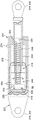
FIG. 8 is a cross-sectional view of an example of an inerter having a rod coupled to a first terminal and a threaded shaft coupled to a second terminal and including a flywheel threadably engaged to the threaded shaft and configured to rotate in proportion to axial acceleration of the rod and the first terminal relative to the threaded shaft and the second terminal;
FIG. 9 is an enlarged cross-sectional view of the flywheel taken along line 9 of FIG. 8 and showing the bearing rotatably coupling the flywheel ring to the inertance rod, and further showing the threaded engagement of the flywheel with the threaded shaft;
FIG. 10 is a cross-sectional view of an example inerter integrated in an unbalanced hydraulic actuator and showing an inerter flywheel rotatably coupled to a piston of the hydraulic actuator;
FIG. 11 is a cross-sectional view of an example inerter with flywheel protrusions for generating viscous damping within the hydraulic fluid during rotation of the flywheel;
FIG. 12 is a perspective view of an example of the inerter taken along line 12 of FIG. 11 and showing a plurality of radially extending flywheel blades circumferentially spaced about the flywheel perimeter;
FIG. 13 is a cross-sectional view of an example inerter integrated into a partially balanced hydraulic actuator having an internal piston axially slidable within a piston rod;
FIG. 14 is a cross-sectional view of an example inerter integrated into a balanced hydraulic actuator having opposing piston sides of substantially equal cross-sectional areas;
FIG. 15 is a cross-sectional view of an example inerter integrated into a hydraulic actuator, and wherein the flywheel is rotatably housed within a piston of the hydraulic actuator, and includes an electric flywheel motor and brake for actively controlling rotation of the flywheel;
FIG. 16 is an enlarged cross-sectional view of the flywheel and piston taken along line 16 of FIG. 15 and showing an electric flywheel motor having permanent magnets mounted to the periphery of the flywheel and windings mounted to the inner wall of the piston;
FIG. 17 is a cross-sectional view of an example of an inertance vessel integrated into a hydraulic actuator, and wherein a flywheel and threaded shaft are rotatably coupled to an actuator end wall and fixedly coupled to a piston of a rod;
FIG. 18 is an enlarged cross-sectional view of the flywheel and piston taken along line 18 of FIG. 17 and showing the flywheel ring rotatably coupled to the actuator end wall and the piston threadably engaged to the threaded shaft in a manner such that linear translation of the rod relative to the threaded shaft causes rotation of the flywheel and threaded shaft;
FIG. 19 is a cross-sectional view of an example of a flywheel rotatably coupled to an actuator end wall and having an electric flywheel motor including permanent magnets mounted to a periphery of the flywheel and windings mounted to a housing side wall of the actuator;
FIG. 20 is a cross-sectional view of another example of a flywheel having an electric flywheel motor and further including a brake configured to provide dynamic braking of the flywheel;
FIG. 21 is a cross-sectional view of an example inerter integrated into a linear electromechanical actuator and showing a flywheel rotatably coupled to an actuator motor and threadably engaged to a threaded shaft;
FIG. 22 is a cross-sectional view of an example inerter integrated into a hydraulic actuator and shows the symbols x, x0, x1, and x2 representing reference points of translation of the rod end, head end, piston, and flywheel, respectively, where these symbols are used to characterize the derivation of the transfer function of the response of the actuator with the integrated inerter;
FIG. 23 is a graph of frequency versus amplitude (e.g., amplitude) for an actuator operating at operating pressures of 3000psi, 5000psi, and 8000psi and illustrating a reduction in amplitude for an actuator damped by an inertance relative to an amplitude for an actuator undamped by an inertance;
FIG. 24 is a flow chart having one or more operations that may be included in a method of using an inertance damping actuator.
Detailed Description
Referring now to the drawings, wherein the showings are for purposes of illustrating various examples of the disclosure, FIG. 1 shows a block diagram of a hydraulic actuator 204, the hydraulic actuator 204 being coupled between the support structure 116 and the movable device 124 and configured to move or actuate the movable device 124. The block diagram advantageously includes inerter 300 for damping rotation of actuator 202. Inerter 300 is shown coupled between support structure 116 and moveable device 124, and is configured to improve the dynamic response of moveable device 124 during actuation by actuator 202, as described in more detail below. In the example shown in fig. 1 and 4-9, inertance vessel 300 is provided as a separate component from actuator 202. However, in other examples described below (e.g., fig. 2 and 10-21), inerter 300 is integrated into actuator 202.
The actuator 202 includes a piston 216 coupled to a piston rod 224. The piston 216 is slidable within an actuator housing 228 (e.g., a cylinder). Actuator 202 also includes a rod end 214 and a head end 212, rod end 214 and head end 212 being axially movable relative to one another in response to pressurized hydraulic fluid acting in an unbalanced manner on one or both sides of a piston 216 within an actuator housing 228. In the example shown, the rod end 214 is coupled to the movable device 124 and the cap end 212 is coupled to the support structure 116. However, the actuator 202 may be mounted such that the rod end 214 is coupled to the support structure 116 and the cap end 212 is coupled to the movable device 124.
Still referring to fig. 1, the inerter 300 includes a first terminal 302 and a second terminal 304, the first terminal 302 and the second terminal 304 being axially movable or translatable relative to each other along an inerter axis 306 (fig. 8) in correspondence with actuation of the movable device 124 by the actuator 202. In the example shown, the first terminal 302 is coupled to the movable device 124 and the second terminal 304 is coupled to the support structure 116. However, the inerter 300 can be mounted such that the first terminal 302 is coupled to the support structure 116 and the second terminal 304 is coupled to the mobile device 124. In an example not shown, the support structure to which inerter 300 is coupled can be a different support structure than support structure 116 to which actuator 202 is coupled.
The inerter 300 includes an inerter rod 308, the inerter rod 308 coupled to the first terminal 302 and axially movable (e.g., translatable) with the first terminal 302. Inerter rod 308 can be aligned or parallel to inerter axis 306. Inerter rod 308 can be hollow to define a rod bore 310. The threaded shaft 322 is coupled to the second terminal 304 and is axially movable (e.g., translatable) with the second terminal 304. Threaded shaft 322 may be aligned or parallel with inerter axis 306. The threaded shaft 322 has a free end 324 that is receivable within the rod bore 310. The threaded shaft 322 may be hollow or may include a shaft aperture 323 that opens onto a free end 324 of the threaded shaft 322. Threaded shaft 322 may include a radial passage 325 extending radially from shaft bore 323 to the outside of threaded shaft 322 to allow fluid flow between the outside of threaded shaft 322 and shaft bore 323. The axial bore 323 can allow fluid (e.g., hydraulic fluid, not shown) to flow from a fluid cavity at the second terminal end 304 (for the non-integrated inerter in fig. 1) or the cap end 212 (for the integrated inerter of fig. 2) through the axial bore 323 and into a fluid cavity at the free end 324 (fig. 8) of the threaded shaft 322 to allow the fluid to lubricate moving portions of the bearing 328 and/or at the flywheel ring 318. The size (e.g., diameter) of the shaft bore 323 and the size (e.g., diameter) and number of the radial passages 325 may be configured to distribute the fluid flow to the bearing 328 and the flywheel ring 318.
As shown in fig. 1, inertance vessel 300 includes a flywheel 314 (e.g., a rotating mass). In some examples (e.g., fig. 6 and 8-16), the flywheel 314 may be threadably coupled to a threaded shaft 322, the threaded shaft 322 converting linear motion of the threaded shaft 322 into rotational motion of the flywheel 314. Flywheel 314 is configured to rotate in proportion to axial movement of inertance rod 308 relative to threaded shaft 322 corresponding to actuation of moveable device 124 by actuator 202. In this regard, the freewheel 314 is configured to rotationally accelerate and decelerate in proportion to axial acceleration and deceleration of the inerter rod 308 (e.g., coupled to the first terminal 302) relative to the threaded shaft 322 (e.g., coupled to the second terminal 304).
Advantageously, the freewheel 314 is coupled to the inerter rod 308 at a freewheel ring 318 and threadably engaged to a threaded shaft 322, as shown in fig. 1, 8-9, and 14 and described in more detail below. However, in other examples, as shown in fig. 10-13 and 15-16 and described below, the flywheel ring 318 may be coupled to the piston 216. In further examples, as shown in fig. 17-20 and described below, the flywheel ring 318 may be coupled to the actuator housing 228.
Regardless of the components to which the flywheel 314 is coupled, the flywheel 314 can include at least one bearing 328 (e.g., a thrust bearing 328) at the flywheel ring 318 to rotatably couple the flywheel 314 to the inerter rod 308 (fig. 1, 8-9, and 14), the piston 216 (fig. 10-13 and 15-16), or the actuator housing 228 (fig. 17-20). Bearing 328 allows flywheel 314 to translate axially with inerter rod 308 as flywheel 314 rotates on the threads of threaded shaft 322 in response to axial movement of inerter rod 308 relative to threaded shaft 322. Advantageously, by coupling flywheel 314 to components at flywheel ring 318 (i.e., inertance rod 308, piston 216, or actuator housing 228) rather than components at flywheel periphery 316, flywheel 314 exhibits limited bending in the axial direction during high frequency, oscillating, axial acceleration of first terminal 302 relative to second terminal 304. This axial bending of the flywheel mass will reduce flywheel rotational motion during high frequency, oscillatory, axial acceleration.
Still referring to the example of fig. 1, the support structure 116 is shown as a spar 118 configured as a wing 114 of the aircraft 100. The movable device 124 is shown as a flight control surface 122 of a flight control system 120 of the aircraft 100. Flight control surface 122 may be hingedly coupled to rigid support structure 116, such as spar 118 or other structure. Flight control surface 122 may pivot about a hinge axis 126. Flight control surface 122 can include any of a variety of different configurations including, but not limited to, spoilers, ailerons, elevators 112, elevons (elevons), flaperons, rudders 108, high lift devices such as slats, trailing edge flaps, or any other type of movable device 124.
In one example, inerter 300 can be configured such that rotation of flywheel 314 reduces the actuator load oscillation amplitude at resonance of coupled actuator 202 and moveable device 124 by at least about 10% relative to the actuator load oscillation amplitude generated using the same actuator 202 without inerter 300. Advantageously, the presently disclosed inerter 300 allows the operating bandwidth of the actuator 202 to encompass or match the resonant frequency of the coupled movable device 124 and actuator 202 without the possibility of an oscillatory response, and without the possibility of exceeding the strength capabilities of the flight control surface 122 and the mounting system (not shown) of the actuator 202, and/or without the possibility of deflecting the flight control surface 122 that can aerodynamically pan the aircraft 100.
The presently disclosed example of inerter 300 allows for a reduction in the overall size and weight of the actuator 202 system without the possibility of an oscillating response. More specifically, inerter 300 allows for a reduction in inertial load on actuator 202, which in turn allows for a reduction in piston cross-sectional area of actuator 202, as well as a reduction in the size and weight of other hydraulic system components (including reservoir, tubing diameter, accumulator, pump, and other components). In this regard, the inerter 300 increases the power density for the hydraulic actuator system in any application where the dynamic response is limited by piston cross-sectional area or load inertia. The presently disclosed example of inerter 300 can be implemented with a hydraulic actuator 204, the hydraulic actuator 204 configured to operate at a working pressure of at least 5000 psi. For example, the example inerter 300 may be implemented with the hydraulic actuator 204 operating at a working pressure of about 3000psi, and in some examples, the hydraulic actuator 204 may operate at a working pressure of about 8000 psi. The relatively high operating pressure of hydraulic actuator 204 may help to reduce the total flow of hydraulic fluid through the hydraulic system (e.g., flight control system 120), which may result in a reduced volume requirement of the hydraulic fluid reservoir and accumulator.
In the case of aircraft 100, the reduced size of actuator 202 may reduce the amount by which such actuator 202 protrudes outside of an exterior mold line (not shown) of aircraft 100, thereby resulting in a reduction in aerodynamic drag. Still further, examples of the presently disclosed inerter may allow for a reduction in the amount of exhaust power from an aircraft propulsion unit (e.g., a gas turbine engine), which may provide the possibility of using a higher bypass ratio gas turbine engine, such as in commercial aircraft applications. A reduction in the size of the hydraulic system, a reduction in aerodynamic drag, and/or a reduction in exhaust power may translate into an increase in aircraft performance, including but not limited to improved fuel efficiency, range, and/or payload capacity.
Although examples of the presently disclosed inerter are described in the context of the linear hydraulic actuator 204, the inerter 300 can be implemented in other types of actuators 202, including but not limited to rotary hydraulic actuators, electro-hydraulic actuators (e.g., rotary or linear), mechanical actuators, electromechanical actuators, and other types of actuators. In one example (see fig. 21), the electromechanical actuator 242 may be a linear electromechanical actuator having a threaded shaft 322 coupled to the movable device 124. As described in more detail below with reference to fig. 21, the linear electromechanical actuator 242 may include an electric actuator motor 244 for causing axial movement of the threaded shaft 322. The flywheel 314 may be threadably engaged to the threaded shaft 322 and may be configured to rotationally accelerate and decelerate in proportion to the axial acceleration and deceleration of the threaded shaft 322 during actuation of the movable device 124 by the linear electromechanical actuator 242.
It should also be noted that although the presently disclosed inerter example is described in the context of aircraft flight control system 120, any of inerters 300 can be implemented in any type of open-loop or closed-loop control system for use in any of a variety of different applications in any industry, without limitation thereto. In this regard, the inerter 300 of the present disclosure can be implemented in any vehicular application or non-vehicular application. For example, inerter 300 can be implemented in any marine, ground, air, and/or aerospace application, as well as in any vehicular or non-vehicular system, subsystem, assembly, subassembly, structure, building, machine, and application that uses actuators to actuate a movable device.
In some examples, inertance vessel 300 can be implemented to dampen the motion of a movable device configured to control the direction of vehicle travel. For example, inerter may be implemented to dampen the motion of an aerodynamic control surface of an aircraft, a hydrodynamic control surface of a marine vessel, a thrust director including a thrust vectoring nozzle of an aircraft or vehicle (e.g., a rocket), or any other type of mechanical device that affects the direction of travel of the vehicle and may be susceptible to external oscillatory forces. In a particular example of a wheeled vehicle configured to move over land, any of the presently disclosed inerter examples may be implemented in a steering system to control or avoid wheel vibrations, such as may occur in steerable wheels of an aircraft landing gear (such as a nose gear).
Fig. 2 is a block diagram of an example of an inerter 300 integrated into a hydraulic actuator 204, the hydraulic actuator 204 coupled between a support structure 116 and a flight control surface 122 of a flight control system 120 of an aircraft 100. In the example shown, the actuator 202 is a linear hydraulic actuator 204 having a piston 216 coupled to a rod (e.g., a piston rod 224) and axially slidable within a housing (not shown). In the example shown, the flywheel 314 of the inerter 300 is rotatably coupled to the piston 216 at a flywheel ring 318. The flywheel 314 is threadably coupled to the threaded shaft 322 and is configured to rotationally accelerate in proportion to the axial acceleration of the piston 216 and rod relative to the threaded shaft 322. However, as described above, the flywheel 314 may be rotatably coupled to the piston 216 (e.g., fig. 10-16), or the flywheel 314 may be rotatably coupled to the head end 212 (e.g., fig. 17-20) or the rod end 214 of the actuator housing 228.
As described above, the threaded shaft 322 may include a shaft bore 323 open at the free end 324 and have a radial passage 325 to allow fluid (e.g., hydraulic fluid) to flow from the cap end chamber 236 through the shaft bore 323 at the cap end 212 and out of the free end 324 of the threaded shaft 322 to allow fluid to lubricate the bearings 328 and/or moving parts of the flywheel ring 318. The axial bore 323 and radial passage 325 can be included in any of the inerter 300 examples disclosed herein.
In the present disclosure, for an example in which inerter 300 is integrated into actuator 202, stem end 214 or cap end 212 of actuator 202 serves as a first terminal 302 of inerter 300, and the remaining stem end 214 or cap end 212 of actuator 202 serves as a second terminal 304 of inerter 300. In this regard, the terms "first terminal" and "second terminal" are not used interchangeably with the terms "rod end" and "cap end," respectively. Further, for examples where inertance 300 is integrated into actuator 202, the term "rod" is used interchangeably with the terms "piston rod" and "inertance rod". Similarly, for examples in which inerter 300 is integrated into actuator 202, the term "housing" is used interchangeably with the terms "actuator housing" and "inerter housing".
Fig. 3 is a perspective view of the aircraft 100 with one or more inertias 300 for controlling and/or damping one or more actuators 202. The aircraft 100 may include a fuselage 102 and a pair of wings 114 extending outwardly from the fuselage 102. The aircraft 100 may include a pair of propulsion units (e.g., gas turbine engines). As described above, each wing 114 may include one or more moveable devices 124 configured as flight control surfaces 122, the moveable devices 124 may be actuated by actuators 202, the actuators 202 being dampened and/or assisted by inerter 300. Such flight control surfaces 122 on the wing 114 may include, but are not limited to, spoilers, ailerons, and one or more high lift devices such as slats and/or trailing edge flaps. At the aft end of fuselage 102, tail wing 104 may include one or more horizontal tails 110 and vertical tails 106, any one or more of horizontal tails 110 and vertical tails 106 may include flight control surfaces 122, such as elevators 112, rudders 108, or other types of movable devices 124 that may be actuated by actuators 202, actuators 202 being dampened and/or assisted by inerter 300.
FIG. 4 is a top view of a portion of the wing 114 of FIG. 3 showing the aileron actuated by a hydraulic actuator 204 located on one end of the aileron and having inerter 300 located on the opposite side of the aileron 130. The ailerons 130 may be hingedly coupled to a fixed support structure 116 (such as a spar 118) of the wing 114. In fig. 4, the hydraulic actuator 204 and inerter 300 are provided as separate components and may each be coupled between the support structure 116 (e.g., spar 118) and the aileron 130.
Fig. 5 is a cross-sectional view of the wing 114 of fig. 4, showing an example of a linear hydraulic actuator 204 mechanically coupled between the spar 118 and one end of the aileron 130. In the example shown, rod end 214 of hydraulic actuator 204 is coupled to bell crank 128. The bell crank 128 is hingedly coupled to the aileron in a manner such that linear actuation of the hydraulic actuator 204 causes the aileron to pivot about the hinge axis 126. The cap end 212 of the hydraulic actuator 204 is coupled to the spar 118.
Fig. 6 is a cross-sectional view of the wing 114 of fig. 4 and illustrates an example of an inerter 300 coupled between the spar 118 and the aileron 130. As described above, inertance vessel 300 is located on the opposite end of the aileron from hydraulic actuator 204. The first terminal 302 of the inerter 300 is coupled to the bellcrank 128. The second terminal end 304 of the inerter 300 is coupled to the spar 118. Since the hydraulic actuator 204 and inertance 300 are coupled to the same movable device 124 (i.e., aileron 130), the relative axial acceleration of the head end 212 and rod end 214 of the actuator 202 causes a proportional axial acceleration of the first and second terminals 302, 304 of the inertance 300, resulting in a rotational acceleration of the flywheel 314.
Fig. 7 is a partial cross-sectional view of an example of double acting hydraulic actuator 204, double acting hydraulic actuator 204 having a head end 212 and a rod end 214 that are axially movable relative to each other during actuation of movable device 124. As described above, the rod end 214 and the head end 212 may be coupled to the support structure 116 and the movable device 124 exclusively of one another. For example, the stem end 214 may be coupled to the support structure 116 and the cap end 212 may be coupled to the mobile device 124, or the stem end 214 may be coupled to the mobile device 124 and the cap end 212 may be coupled to the support structure 116.
In fig. 7, the piston 216 is coupled to the free end 324 of the piston rod 224 and is axially slidable within the actuator housing 228. The piston 216 divides the actuator housing 228 into a cap end chamber 236 and a rod end chamber 238. The actuator housing 228 of the double acting hydraulic actuator 204 includes a pair of fluid ports 234 through which pressurized hydraulic fluid enters and exits a head end chamber 236 and a rod end chamber 238 to move the piston 216 within the actuator housing 228. In any of the presently disclosed examples, the hydraulic actuator 204 may also be configured as a single-acting actuator (not shown), wherein the actuator housing 228 includes a single fluid port 234 for receiving pressurized hydraulic fluid in the actuator housing 228 as a means of moving the piston 216 in one direction within the actuator housing 228, and optionally a biasing member (e.g., a spring, not shown) for moving the piston 216 in an opposite direction.
FIG. 8 is a partial cross-sectional view of an example of a inerter 300 having an inerter housing 330, the inerter housing 330 including a flywheel 314 and having an inerter side wall 334 and an opposing inerter end wall 332. One inerter end wall 332 can include a housing bore through which inerter rod 308 extends and terminates at first terminal end 302. Inerter 300 includes a threaded shaft 322 coupled to inerter end wall 332 at second terminal end 304. In the example of fig. 8, the flywheel 314 is coupled to one end of the inertance rod 308 and threadably engages to the threaded shaft 322. The flywheel 314 rotates in proportion to the axial acceleration of the inerter rod 308 and the first terminal 302 relative to the threaded shaft 322 and the second terminal 304.
Fig. 9 is an enlarged cross-sectional view of fig. 8, showing the flywheel 314 coupled to the inertance tube rod 308 at the flywheel ring 318. The flywheel ring 318 may also be threadably engaged to the threaded shaft 322. In the example shown, the threaded shaft 322 is configured as a ball screw 326 having a helical groove for receiving a ball bearing that couples a similarly configured helical groove in the flywheel ring 318 with the ball screw 326 with minimal friction. Although not shown, the flywheel ring 318 may include ball nuts for circulating ball bearings coupled to the flywheel 314 to the ball screw 326. In another example not shown, the threaded shaft 322 may include a lead screw having threads, with the freewheel ring 318 directly engaged to the lead screw. It will be appreciated that the flywheel 314 may be configured to engage any one of a number of different types of threaded shaft configurations and is not limited to the example of ball screw 326 shown in FIG. 9.
Also shown in fig. 9 is an example of a bearing 328 for coupling flywheel ring 318 to inertance tube 308 such that inertance tube 308 and flywheels 314 can translate in unison as flywheels 314 rotate due to threaded engagement with threaded shafts 322. Although bearing 328 is shown as a ball bearing, bearing 328 may be disposed in any of a variety of different configurations that enable axial coupling of flywheel 314 to inertance vessel rod 308 with a minimal amount of axial lost motion (free play). For example, the bearing 328 may be configured as a rolling bearing (not shown). In further examples, flywheel 314 can be coupled to inerter rod 308 without bearings, while allowing flywheel 314 to rotate during translation of inerter rod 308 and flywheel 314 relative to threaded shaft 322.
Fig. 10 is a cross-sectional view of an example inerter 300 integrated into a hydraulic actuator 204, the hydraulic actuator 204 having a housing containing a piston 216. Actuator 202 is a double-acting actuator that includes a pair of fluid ports 234 for receiving pressurized hydraulic fluid in a head end chamber 236 and a rod end chamber 238 on opposite sides of piston 216. The actuator 202 is an unbalanced actuator 206 in which one of the piston sides 218 has a larger cross-sectional area than the opposing piston side 218. The piston 216 may include a piston 216 seal (e.g., an O-ring seal, not shown) extending around the piston perimeter 220 for sealing the piston perimeter 220 to the actuator sidewall 232.
As described above, for an example in which the inerter 300 is integrated into the actuator 202, the stem end 214 or the cap end 212 of the actuator 202 serves as the first terminal 302 of the inerter 300, and the remaining stem end 214 or the cap end 212 of the actuator 202 serves as the second terminal 304 of the inerter 300. In the example shown, the flywheel 314 is mounted in the head end chamber 236 and is rotatably coupled to the piston 216 at a flywheel ring 318. The flywheel 314 may be threadably engaged to a threaded shaft 322 that extends through the piston 216 and into the rod bore 310. The flywheel 314 is configured to rotationally accelerate in proportion to the axial acceleration of the piston 216 and piston rod 224 relative to the threaded shaft 322.
Fig. 11 shows an example of an inerter 300 having flywheel protrusions 320, the flywheel protrusions 320 for creating viscous damping during rotation of the flywheel 314 when the flywheel 314 is immersed in hydraulic fluid. The flywheel protrusion 320 generates or increases the viscous damping capacity of the inerter 300 during rotation of the flywheel 314, and thus increases the damping capacity of the inerter 300.
Fig. 12 is a perspective view of an example inerter 300 having a plurality of radially extending flywheel blades circumferentially spaced about the flywheel perimeter 311. During rotation of the flywheel 314, the flywheel blades may create viscous damping capacity and increase the inerting capacity of the inertance vessel 300. Although fig. 12 illustrates the flywheel projections 320 as radially extending flywheel blades, the flywheel 314 may be provided with flywheel projections 320 extending from any portion of the flywheel 314, the flywheel projections 320 including one or both of the opposite sides of the flywheel 314. Further, the flywheel protrusion 320 may be disposed in any geometric size, shape, or configuration, without limitation, and without limitation, to a flywheel blade.
Fig. 13 is a cross-sectional view of an example inertance vessel 300 integrated into a hydraulic actuator 204 of an actuator 208 configured to be partially balanced. The partially balanced actuator 208 includes an inner piston 226 coupled to a free end 324 of a threaded shaft 322. The inner piston 226 may slide axially within the rod bore 310 and may be rotatably coupled to an end of the threaded shaft 322 such that the inner piston 226 cannot rotate relative to the rod bore 310 during axial movement of the piston rod 224 relative to the threaded shaft 322. Although not shown, the perimeter of the inner piston 226 may be sealed (e.g., via an O-ring) to the stem wall 312 of the stem bore 310. The inclusion of the inner piston 226 may reduce the total volume of hydraulic fluid required to fill the cap end chamber 236 during extension of the piston rod 224 relative to the increased volume of hydraulic fluid required to fill the cap end chamber 236 of an example lacking the inner piston 226 (e.g., fig. 8).
Fig. 14 is a partial cutaway view of an example inertance vessel 300 integrated into a hydraulic actuator 204, the hydraulic actuator 204 configured as a balance actuator 210 with opposing piston sides 218 of substantially equal cross-sectional area. The housing may include a separator wall 240, the separator wall 240 separating the portion of the housing containing the flywheel 314 from the portion of the housing containing the piston 216. The cap end chamber 236 is located on one of the piston sides 218, while the rod end chamber 238 is located on the opposite piston side 218. The piston 216 may be mounted on a piston rod 224. In fig. 14, one end of the piston rod 224 extends through the actuator end wall 230 and terminates at the rod end 214 (e.g., the first terminal end 302). The opposite end of piston rod 224 extends through separator wall 240. The flywheel 314 is rotatably coupled to the piston rod 224 in the manner described above.
Fig. 15 is a partial cross-sectional view of an example inerter 300 with an electric flywheel motor 350 integrated into the hydraulic actuator 204. Flywheel motor 350 may use the electromotive force from the integrated flywheel motor 350 to facilitate active control of the rotation of flywheel 314. Active control may include applying torque to the flywheel 314 using the flywheel motor 350 to resist or assist the torque generated by the flywheel 314 due to axial acceleration of the first terminal 302 relative to the second terminal 304. Flywheel motor 350 may be configured to provide active damping and/or active braking of actuator 202 as well as load inertia.
FIG. 16 is an enlarged cross-sectional view of FIG. 15, showing the flywheel 314 rotatably coupled to and housed within the generally hollow piston 216, the piston 216 being substantially slidable within the actuator housing 230. A flywheel motor 350 is also shown incorporated into the flywheel 314 and piston 216, and is configured to actively control the rotation of the flywheel 314 in correspondence with the relative axial movement of the rod and threaded shaft 322. Flywheel motor 350 may be operated to accelerate and/or decelerate flywheel 314 by applying a torque to flywheel 314 that corresponds with (e.g., is in the same direction as) the direction of rotation of flywheel 314 or is opposite the direction of rotation of flywheel 314. In this manner, the flywheel motor 350 may apply a torque to the flywheel 314 to resist or assist the flywheel torque due to the axial acceleration of the first terminal 302 relative to the second terminal 304.
In the example of fig. 16, the flywheel motor 350 is a permanent magnet Direct Current (DC) motor having one or more permanent magnets 354 mounted to the flywheel 314. For example, a plurality of permanent magnets 354 may be circumferentially spaced about the flywheel perimeter 316. In addition, flywheel motor 350 may include a plurality of windings 352 mounted to piston 216. In one example, the plurality of windings 352 may be spaced circumferentially around the piston inner wall 222 (e.g., fig. 15-16). In another example, as described below, the plurality of windings 352 may be spaced circumferentially around the sidewall 232 of the housing (e.g., fig. 19-20). In other examples, the flywheel motor 350 may be a brushless dc motor or some other motor configuration and is not limited to the permanent magnet dc motor configuration as shown in fig. 15-16 and 19-20. In an example not shown, a linear position sensor may be included in the actuator 202 to sense the linear position of the piston 216 and generate a signal indicative of the linear piston position to commutate the flywheel motor 350 in correspondence with the piston position.
As described above, the flywheel motor 350 in fig. 15-16 may be configured to assist or assist the flywheel 314 in rotating for a commanded direction of motion of the movable device 124. For example, the flywheel motor 350 may provide torque to accelerate the flywheel 314 as the movable device 124 begins to move toward the commanded position. The amount of torque applied to the flywheel 314 by the flywheel motor 350 may be approximately equal to the amount of torque required to rotationally accelerate the flywheel 314 due to axial acceleration of the threaded shaft 322 relative to the rod. By using the flywheel motor 350 to remove the torque required to spin up the flywheel 314, the piston 216 may move to the commanded position faster than if the flywheel motor 350 did not spin up the flywheel 314. In this manner, flywheel motor 350 may allow for faster responsiveness of movable device 124 than conventional actuator 202. Due to the risk of control system instability, the level of damping provided by the inerter 300 with active control of the flywheel 314 can be greater than is feasible in a closed loop control system without active control. Although fig. 15-16 illustrate the flywheel motor 350 incorporated into the inerter 300 integrated with the actuator 202, the flywheel motor 350 may also be incorporated into the inerter 300 as a separate component from the actuator 202 (e.g., fig. 4-8).
In another example of active control, flywheel motor 350 may operate in a manner that provides torque to decelerate flywheel 314 as movable device 124 approaches a commanded position. In this regard, the flywheel motor 350 may operate as a brake to oppose the flywheel torque generated by the axial deceleration of the threaded shaft 322 relative to the piston rod 224. Actively controlling the flywheel 314 to rotate in this manner may prevent or limit position overshoot of the movable device 124 and thereby increase stability of the movable device 124. In such an arrangement, the actuator 202 and inerter 300 may be configured with failure modes that ensure that the actuator 202 can exhibit a desired damping response in a manner that prevents under-damping of the movable device 124 without active motor control. Inertial container 300 with flywheel motor 350 for active control may be connected to movable device 124 rather than being part of actuator 202, such that in the event actuator 202 is disconnected from movable device 124, or in the event actuator 202 fails to hold the load of movable device 124, flywheel motor 350 may operate in a manner that prevents under-damped motion of movable device 124 for a given failure mode.
Still referring to FIG. 16, in another example of active control, flywheel motor 350 may include a brake 360 configured to provide dynamic braking of flywheel 314. In this regard, brake 360 may operate in a manner that decelerates flywheel 314 or increases the existing deceleration of flywheel 314. For examples that include flywheel motor 350, brake 360 may operate in a manner that increases the existing deceleration of flywheel 314 resulting from the rotational resistance of flywheel motor 350. Additionally, flywheel motor 350 may operate in a manner that counters disturbances (e.g., undesired motion) of actuator 202.
In the example of fig. 16, the brake 360 may be configured as a disc brake having a brake pad 364. Flywheel 314 may function as a brake disc with which brake pads 364 may frictionally engage during braking. In other examples not shown, a separate brake disk may be provided, which may be coupled directly or indirectly to flywheel 314. In the example shown, a hydraulic brake cylinder (not shown) may be included to actuate brake pads 364 into frictional engagement with one or both of opposing axial surfaces 362 (e.g., planar surfaces) of flywheel 314 in order to decelerate flywheel 314. Preferably, the brake 360 may include at least two pairs of opposing brake pads 364 located on diametrically opposite sides of the brake disc. Each pair of brake pads 364 may be held in place by brackets 366. Although brake 360 is described and illustrated as a disc brake, inerter 300 may incorporate any one or more different types of brakes, such as a drum brake or any other type of brake capable of decelerating flywheel 314.
Referring to fig. 17, a partial cross-sectional view of another example of an inerter 300 integrated into a hydraulic actuator 204 is shown. The flywheel 314 may be rotatably coupled or attached to the actuator end wall 230, and the actuator end wall 230 may be coupled to the second terminal 304. The piston 216 is fixedly coupled or attached to a piston rod 224, the piston rod 224 extending from the piston 216 through the actuator end wall 230 and coupled to the first terminal end 302. In an alternative example not shown, flywheel 314 may be rotatably coupled to actuator end wall 230, actuator end wall 230 is attached to first terminal 302, and piston rod 224 may be coupled to second terminal 304.
Fig. 18 is an enlarged cross-sectional view of fig. 17, showing the freewheel ring 318 rotatably coupled to the actuator end wall 230 by a bearing 328. Threaded shaft 322 is fixedly coupled to flywheel 314 and is rotatable in unison with flywheel 314. As described above, the piston 216 is fixedly coupled to the piston rod 224 and threadably engaged to the threaded shaft 322 in a manner such that linear translation of the piston rod 224 relative to the threaded shaft 322 causes concurrent rotation of the flywheel 314 and the threaded shaft 322. As described above, axial movement of the threaded shaft 322 relative to the piston rod 224 may correspond to actuation of the movable device 124 by the actuator 202.
Fig. 19 illustrates an example of a flywheel 314, the flywheel 314 rotatably coupled to the actuator end wall 230 and incorporating a flywheel motor 350 for actively controlling the rotation of the flywheel 314 in the manner described above. The flywheel motor 350 can include permanent magnets 354 mounted to the flywheel perimeter 316. For example, as described above with respect to fig. 16, a plurality of permanent magnets 354 may be circumferentially spaced about the flywheel perimeter 316. Fig. 19 also shows a plurality of windings 352 spaced circumferentially around the actuator sidewall 232 of the actuator housing 228.
Fig. 20 illustrates an example of flywheel 314, flywheel 314 including a brake 360 configured to provide dynamic braking of flywheel 314. In the illustrated example, brake 360 is configured as a disc brake having one or more pairs of brake pads 364 for frictionally engaging opposing axial faces 362 of flywheel 314. In fig. 20, the brake 360 may be configured and operated similar to the arrangement shown in fig. 16 and described above.
Fig. 21 shows an example of an inerter 300 integrated into a linear electromechanical actuator 242. The electromechanical actuator 242 may extend between the support structure 116 (fig. 2) and the movable device 124 (fig. 2). The electromechanical actuator 242 may include an electric actuator motor 244 supported by the actuator housing 228. The first terminal 302 may be coupled to the movable device 124. The electromechanical actuator 242 may include a second terminal 304, and the second terminal 304 may be coupled to the support structure 116. Alternatively, the first terminal 302 may be coupled to the support structure 116 and the second terminal 304 may be coupled to the movable device 124.
The electromechanical actuator 242 may include a threaded shaft 322 (e.g., Acme threaded shaft, ball screw, etc.) extending through an actuator motor 244 and terminating at the first terminal 302. The actuator motor 244 may be operatively coupled to the threaded shaft 322 by a motor shaft coupling 246, and the motor shaft coupling 246 may be threadably engaged to the threaded shaft 322. Operation of the actuator motor 244 may cause axial movement of the threaded shaft 322 to actuate the movable device 124. In this regard, the threaded shaft 322 may move axially in proportion (e.g., in magnitude and direction) to the angular displacement of the actuator motor 244. The flywheel 314 may be threadably engaged to the threaded shaft 322. Additionally, the flywheel ring 318 may be rotatably coupled to the actuator motor 244 via a bearing 328 such that axial acceleration of the threaded shaft 322 causes rotational acceleration of the flywheel 314. The flywheel 314 may be configured to rotationally accelerate and decelerate in proportion to the axial acceleration and deceleration of the threaded shaft 322 (e.g., relative to the actuator motor 244) during actuation of the movable device 124.
In this regard, rotation of flywheel 314 during actuation of electromechanical actuator 242 of fig. 21 may provide any one or more of the advantages described herein for improving the dynamic response of movable device 124 during actuation of electromechanical actuator 242. For example, the flywheel 314 may reduce the actuator load oscillation amplitude in the resonance of the coupled electromechanical actuator 242/movable device 124. Additionally, although not shown in fig. 21, a flywheel motor 350 (e.g., fig. 16) and/or a dynamic brake 360 (fig. 16) may optionally be included in the flywheel 314 to allow the rotation of the flywheel 314 to be actively controlled using any one or more of the flywheel control techniques described herein.
Fig. 22 is a cross-sectional view of an example inerter 300 integrated into the hydraulic actuator 204 described above and shown in fig. 10. FIG. 22 includes a symbol X, X representing reference points for translation of the rod end 214, the cap end 212, the piston 216, and the flywheel 314, respectively0、X1And X2. Symbol X, X0、X1And X2Is a transfer function that mathematically characterizes the device response of FIG. 22, described below The parameters used in the derivation of (equation 220). Table 1 includes a list of parameters used in the derivation of the transfer function. Each listed parameter includes an indication of the physical type of the parameter and a brief description of the parameter.

Included in equations 100 through 210 are assumptions following the derivation of the transfer function of equation 220. Referring to the example apparatus of FIG. 22, the total reaction force F (e.g., at rod end 214) may be calculated as piston 216 reaction force F as shown in equation 1001Force F reacting with flywheel 3142In which F is1And F2The sign of (d) is the same as interference rejection sensing:
F=F1+F2(equation 100)
Torque T generated by flywheel 3142The flywheel rotational inertia J and the flywheel rotational acceleration can be determined using equation 110 Product of (D) and flywheel damping coefficient B and flywheel rotational speed
 Sum of products of (a):

flywheel reaction force F2Can be calculated as flywheel torque T using equation 1202And the threading rate r (e.g., pitch) of the threaded shaft 322. The thread speed may be described as the linear distance traveled per revolution of the flywheel 314:

the rotation of the flywheel 314 may be represented by the angular displacement or rotation angle θ, the rotational speed of the flywheel as represented by equations 130, 140, and 150, respectively And rotational acceleration
 To characterize. The rotational angle θ of the flywheel is the thread speed r and the linear distance x that the flywheel translates as expressed by
 equation 1302The product of (a). The parameter c is a constant representing a linear offset from a common reference. Rotational speed of flywheel Is the thread speed r and the linear speed of the
 flywheel 314 as expressed by equation 140 The product of (a). Acceleration of flywheel rotation
 Is the thread speed r and the linear acceleration of the
 flywheel 314 as expressed by equation 150 The product of (a).
θ+c=rx2(equation 130)


Compliant stress F of flywheel 314 to piston 2163Can be calculated as the flywheel translation X using equation 1602And piston translation X1The product of the difference between and the rotational stiffness Z of the flywheel. For the example device of fig. 22 in which an inerter (e.g., flywheel 314) is integrated into actuator 202, flywheel 314 moves with piston 216 such that flywheel translates X2And piston translation X1And are equal as shown in equation 190 below. In this regard, as shown in equation 190 below, since X is assumed2=X1Whereby piston compliance force F3Is zero (0).
F3=Z(x2-x1) (equation 160)
Will be used for flywheel speed And flywheel acceleration
 Substituting equations 140 and 150 into
 equation 120, the flywheel reaction force F2Can be expressed as follows:

piston reaction force F1Can be calculated as actuator (e.g., piston) reaction inertia M and piston acceleration at rod end 214 Product of (d), actuator (e.g., piston) resistance C and piston velocity
 Product of, and actuator stiffness K and piston displacement X1The sum of the products of (a) and (b), as shown in equation 180:

as described above, for the example shown in FIG. 22, where the inerter (e.g., flywheel 314 and threaded shaft 322) is integrated into the actuator 202 such that the flywheel 314 and piston 216 move in unison, the flywheel translates X2And piston translation X1Equality, as shown in equation 190. Additionally, rod end 214 and piston 216 move in unison, as shown in equation 200. The cap end 212 is at X0Is assumed to be fixed (e.g., non-translational), as shown in equation 210.
x2=x1(equation 190)


The transfer function resulting from performing a laplace transform on a differential equation (not shown) representing the natural frequency of the exemplary device shown in fig. 22 As shown in
 equation 220, where x(s) represents the response of the device of fig. 22, and f(s) represents the input to the device:

natural frequency ω of oscillation of the exemplary device of fig. 22nCan be expressed as shown in equation 230, where K is the actuator stiffness, r is the thread rate, and J is the flywheel rotational inertia, as described above.


FIG. 23 is a graph of frequency 380 versus amplitude 382 (amplitude) of the oscillating response of the dynamic load of the actuator 202 operating at three (3) different operating pressures (3000psi, 5000psi, and 8000 psi). The vertical center line represents the dither frequency of 20Hz corresponding to a dynamic load. The graph of fig. 23 shows that the response amplitude 384 provided by the actuator 202 with the integrated inertance vessel 300 of fig. 22 decreases relative to the response amplitude of the same actuator operating without the inertance vessel. Based on the response amplitude set in the flutter frequency for the actuator 202 operating at 8000psi with the inertance 300 being equal to the response amplitude in the flutter frequency for the actuator 202 operating at 3000psi without the inertance 300, the reduction in response amplitude represents an optimization and optimizes the pitch r of the threaded shaft 322, the flywheel rotational inertia J, and the damping factor ζ (equation 240). For an actuator 202 operating at 8000psi, inerter 300 facilitates a reduction in response amplitude 384 of about 5dB in a dither frequency of 20 Hz.
Fig. 24 is a flow chart having one or more operations that may be included in a method 400 of damping an actuator 202 using an inerter 300. As described above, the damping of the actuator 202 can include reducing the amplitude of actuator load oscillations using the inerter 300. As indicated above, in some examples, the inerter 300 can be a separate component from the actuator 202 and coupled to the same movable device 124 as the actuator 202 (e.g., fig. 1 and 4-9). In other examples, inertance vessel 300 can be integrated into actuator 202 (e.g., fig. 2 and 10-22).
Step 402 of method 400 includes actuating movable device 124 using actuator 202. In an example of the flight control system 120 of the aircraft 100, the method may include using a linear actuator, such as the linear hydraulic actuator 204 or the linear electromechanical actuator 242. For example, fig. 4-6 illustrate a linear hydraulic actuator 204 configured to actuate the aileron 130, the aileron 130 being pivotally mounted to the wing 114 of the aircraft 100. However, as described above, the movable device 124 may be any type of movable device that may be actuated by the actuator 202.
Step 404 of the method 400 includes axially accelerating the first terminal 302 of the inerter 300 relative to the second terminal 304 of the inerter 300 using the inerter 300 coupled to the mobile device 124. As described above, inerter 300 can be coupled between support structure 116 and moveable device 124 (e.g., fig. 4 and 6). For example, the first terminal 302 may be coupled to the movable device 124 and the second terminal 304 may be coupled to the support structure 116, or the first terminal 302 may be coupled to the support structure 116 and the second terminal 304 may be coupled to the movable device 124. Alternatively, inerter 300 can be integrated into actuator 202 (e.g., fig. 10-21), and actuator 202 can be coupled between support structure 116 and moveable device 124. In such examples, as described above, the stem end 214 or the cap end 212 of the actuator 202 serves as a first terminal 302 of the inerter 300 (e.g., is one and the same), and the remaining stem end 214 or the cap end 212 of the actuator 202 serves as a second terminal 304 of the inerter 300 (e.g., is one and the same).
Step 406 of method 400 includes rotationally accelerating flywheel 314 in synchronization with the axial acceleration of first terminal 302 relative to second terminal 304. Since the inerter 300 and the actuator 202 are coupled to the same movable device 124 (e.g., fig. 1 and 4-9), or since the inerter 300 is integrated into the actuator 202 (e.g., fig. 2 and 10-21), the axial acceleration of the first terminal 302 relative to the second terminal 304 is synchronized and proportional to the actuation of the movable device 124 by the actuator 202. In this regard, flyweight 314 rotationally accelerates and decelerates in proportion to axial acceleration and deceleration of first terminal 302 relative to second terminal 304 corresponding to actuation of movable device 124 by actuator 202.
Step 408 of method 400 includes damping motion of actuator 202 in response to rotating flywheel 314. In one example, the method may include reducing an actuator load oscillation amplitude of the movable device 124 in response to rotating the acceleration flywheel 314. Whether the inerter 300 is a separate component from the actuator 202 or the inerter 300 is integrated into the actuator 202, the method can include rotationally accelerating the flywheel 314 in a manner that reduces actuator load oscillation amplitude in resonance of the moveable device 124 coupled to the actuator 202. In one example, as described above, the method may include reducing the actuator load oscillation amplitude by at least 50% relative to the oscillation amplitude of the movable device 124 actuated by the same actuator without the inerter. Inerter 300 can be configured to reduce actuator load oscillation amplitude in a resonant frequency up to about 20Hz (e.g., ± 5 Hz). The movable device 124 may be a flight control surface 122 (e.g., a hydraulically actuated aileron 130) of the aircraft 100, and the resonance (e.g., the resonance frequency) may correspond to flutter of the flight control surface 122 induced by aerodynamic forces acting on the flight control surface 122.
As described above, in examples where the inerter 300 is integrated into the actuator 202, the flywheel 314 can include a plurality of flywheel protrusions 320 (e.g., see flywheel blades of fig. 11-12) extending outwardly from the flywheel 314. The flywheel 314 and flywheel protrusions 320 may be submerged in the hydraulic fluid contained within the head end chamber 236. In such examples, the method may include rotating the flywheel 314 within the hydraulic fluid, and generating or increasing viscous damping of the motion of the actuator 202 in response to rotating the flywheel 314 in correspondence with the actuation of the movable device 124. Viscous damping may contribute to the damping provided by the rotational inertia of flywheel 314.
In other examples, the method may include actively controlling rotation of the flywheel 314 in correspondence with relative axial movement of the piston rod 224 and the threaded shaft 322. For example, the inertance vessel 300 can include or incorporate an electric flywheel motor 350 as described above in the examples shown in fig. 15-16 and 19-20. In some examples, as described above, the actuator 202 may include a linear position sensor (not shown) configured to sense a linear position of the piston 216 within the actuator 202 and generate a signal representative of the piston position. The method may include commutating the flywheel motor 350 in correspondence with the linear position of the piston 216 as indicated by the signal generated by the position sensor.
Active control of the rotation of the flywheel 314 may include accelerating and/or decelerating the flywheel 314 using a flywheel motor 350. For example, flywheel motor 350 may operate in a manner that corresponds to the rotation of flywheel 314 or applies torque to flywheel 314 in the direction of rotation of flywheel 314. In this regard, flywheel motor 350 may assist in the commanded directional movement of actuator 202. In some examples, active control of flywheel rotation may include accelerating flywheel 314 during initiation of actuation of movable device 124 by actuator 202 toward a commanded position. In this regard, flywheel motor 350 may rotationally accelerate flywheel 314 at the onset of axial acceleration of first terminal 302 relative to second terminal 304 by an amount that at least partially or completely eliminates forces at first terminal 302 and second terminal 304 due to actuation of movable device 124 by actuator 202. By rotationally accelerating the flywheel 314 at the beginning of the axial acceleration using the flywheel motor 350, the force required to axially move the first terminal 302 relative to the second terminal 304 may be reduced or eliminated, which may increase the speed at which the actuator 202 moves the movable device 124 toward the commanded position.
Alternatively, flywheel motor 350 may operate in a manner that applies torque to flywheel 314 in opposite directions of rotation of flywheel 314. In this regard, the application of motor generated torque in opposite directions of rotation of the flywheel 314 may resist the torque generated by the relative axial acceleration of the first and second terminals 302, 304. In this regard, active control by flywheel motor 350 may oppose the torque produced by the terminal at one end of the actuator 202 movement when the commanded position is reached. In this manner, the step of actively controlling the rotation of flywheel 314 may include dynamically braking or decelerating flywheel 314 using flywheel motor 350 as actuator 202 approaches the commanded position to prevent position overshoot.
In a further example, active control of the rotation of the flywheel 314 may include decelerating the flywheel 314 using a brake 360 (e.g., fig. 16 and 20) as the actuator 202 approaches a commanded position of the movable device 124 to prevent position overshoot of the commanded position. The method may additionally include dynamically braking rotation of flywheel 314, for example, to counter disturbances (e.g., undesired motion) of actuator 202. The step of dynamically braking (e.g., reducing or decreasing rotational speed) flywheel 314 may be performed using a brake 360 that is operatively engaged to flywheel 314 (e.g., fig. 16 and 20) or to a brake disk (not shown), which may be fixedly coupled to flywheel 314. Alternatively or additionally, the step of dynamically braking flywheel 314 may be performed using rotational resistance generated by flywheel motor 350 as described above.
Further, the present disclosure includes embodiments according to the following clauses:
an inerter, comprising:
a first terminal and a second terminal movable relative to each other along an inertance axis and configured to mutually exclusively couple to a support structure and a movable device actuated by an actuator;
a lever coupled to the first terminal and movable with the first terminal;
a threaded shaft coupled to and movable with the second terminal;
a flywheel having a flywheel ring coupled to at least one of the rod and the threaded shaft; and
the flywheel is configured to rotate in proportion to an axial acceleration of the rod relative to the threaded shaft corresponding to actuation of the movable device by an actuator.
Clause 2. the apparatus of clause 1, wherein:
the threaded shaft is non-rotatably coupled to a second terminal; and
the flywheel is rotatably coupled to the rod and threadably engaged to the threaded shaft in a manner such that axial acceleration of the rod relative to the threaded shaft causes proportional rotational acceleration of the flywheel.
Clause 3. the apparatus of clause 1, wherein:
the inerter is integrated into a linear electromechanical actuator.
the actuator is a linear actuator having a rod end and a cover end axially movable relative to each other during actuation of the movable device, the rod end and the cover end being mutually exclusively coupled to one of the support structure and the movable device.
the inerter is integrated into an actuator, which is a hydraulic actuator having a piston coupled to one end of a rod and axially slidable within a housing;
one of the stem end and the cap end of the actuator serves as the first terminal end of the inerter, and the remaining one of the stem end and the cap end serves as the second terminal end; and
the flywheel is rotatably coupled to one of the piston and the rod at a flywheel ring, the flywheel threadably coupled to the threaded shaft and configured to rotationally accelerate in proportion to an axial acceleration of the piston relative to the threaded shaft.
the inerter is integrated into an actuator, which is a hydraulic actuator having a piston coupled to one end of a rod and axially slidable within a housing, the piston dividing the actuator housing into a head end chamber and a rod end chamber;
one of the stem end and the cap end of the actuator serves as the first terminal end of the inerter, and the remaining one of the stem end and the cap end serves as the second terminal end;
a flywheel rotatably coupled to the second terminal;
the threaded shaft is fixedly coupled to the flywheel and rotates in unison with the flywheel; and
the piston is fixedly coupled to the rod and threadably engaged to the threaded shaft in such a way as to cause rotation of the flywheel and the threaded shaft corresponding to actuation of the movable device by the actuator by linear translation of the rod relative to the threaded shaft.
Clause 7. the apparatus of clause 1, wherein:
the flywheel includes a plurality of flywheel projections that extend outwardly from the flywheel and produce viscous damping during rotation of the flywheel.
the actuator is a hydraulic actuator configured to operate at a working pressure of at least 5000 psi.
a motor configured to actively control rotation of the flywheel in correspondence with relative axial movement of the rod and the threaded shaft.
the motor is a permanent magnet dc motor comprising one or more permanent magnets mounted to the periphery of the flywheel and one or more windings mounted to one of the inner wall of the piston and the side wall of the housing.
Clause 11. the apparatus of clause 6, wherein:
the actuator comprises a linear position sensor configured to sense a linear position of a piston within the actuator; and
the motor commutates in correspondence with the linear position of the piston.
a brake operably coupled to the flywheel and configured to decelerate the flywheel.
Item 13. the apparatus of item 1, wherein:
the movable device is configured to control a direction of travel of the vehicle.
Clause 14. the apparatus of clause 1, wherein:
the movable device is a flight control surface of the aircraft.
a flight control surface pivotably coupled to the support structure;
a hydraulic actuator configured to actuate a flight control surface;
an inerter, comprising:
a first terminal and a second terminal coupled mutually exclusively to the support structure and the flight control surface;
a lever movable with the first terminal;
a threaded shaft movable with the second terminal;
a flywheel coupled to at least one of the rod and the threaded shaft; and the flywheel is configured to rotate in proportion to an axial acceleration of the rod relative to the threaded shaft corresponding to actuation of the flight control surface by the actuator.
actuating the movable device using the actuator;
axially accelerating, using an inerter coupled to the movable device, a first terminal of the inerter relative to a second terminal of the inerter synchronously and proportionally to actuation of the movable device;
rotating a flywheel of the accelerating inerter in proportion to and in synchronism with an axial acceleration of the first terminal relative to the second terminal; and
the actuator load oscillation amplitude of the movable device and the actuator is reduced in response to rotationally accelerating the flywheel.
Clause 17. the method of clause 10, wherein the step of reducing the amplitude of the actuator load oscillations comprises:
reducing actuator load oscillation amplitude in the resonance of the movable device.
reducing actuator load oscillation amplitude in resonant frequencies up to about 20 Hz.
Clause 19. the method of clause 10, wherein:
the movable device is a flight control surface of the aircraft.
the inerter is integrated into an actuator, which is a hydraulic actuator having a piston coupled to one end of a rod and axially slidable within a housing; and
the flywheel is rotatably coupled to one of the piston and the rod, and the flywheel is threadably coupled to the threaded shaft.
Clause 21. the method of clause 10, further comprising the steps of:
the rotation of the flywheel is actively controlled in correspondence with the actuation of the movable device by the actuator.
Clause 22. the method of clause 13, wherein the step of actively controlling the rotation of the flywheel comprises at least one of:
the motor is used to accelerate and decelerate the flywheel.
Clause 23. the method of clause 13, wherein the step of actively controlling the rotation of the flywheel comprises:
during actuation of the actuator to actuate the movable device toward the commanded position, the motor is used to accelerate the flywheel.
at least one of a motor and a brake is used to dynamically brake the flywheel as the actuator approaches the commanded position of the movable device.
Additional modifications and improvements of the present disclosure may be apparent to those of ordinary skill in the art. Accordingly, the particular combination of parts described and illustrated herein is intended to represent only certain examples of the present disclosure, and is not intended to serve as an alternative example or means for limiting the spirit and scope of the present disclosure.
Claims (13)
1. An apparatus for damping an actuator (202), comprising:
inerter (300) comprising:
a first terminal (302) and a second terminal (304) movable with respect to each other along an inerter axis (306) and configured to mutually exclusively couple to a support structure (116) and to a movable device (124) actuated by the actuator (202);
a lever (308) coupled to the first terminal (302) and movable with the first terminal (302);
a threaded shaft (322) coupled to the second terminal (304) and movable with the second terminal (304);
a flywheel (314) having a flywheel ring (318) coupled to at least one of the rod (308) and the threaded shaft (322); and
a motor (350) configured to actively control rotation of the flywheel (314) in correspondence with relative axial movement of the rod (308) and threaded shaft (322);
wherein the flywheel (314) is configured to rotate in proportion to an axial acceleration of the rod (308) relative to the threaded shaft (322) corresponding to actuation of the movable device (124) by the actuator (202).
2. The apparatus of claim 1, wherein:
the threaded shaft (322) is non-rotatably coupled to the second terminal (304); and
the flywheel (314) is rotatably coupled to the rod (308) and threadably engaged to the threaded shaft (322) in a manner such that axial acceleration of the rod (308) relative to the threaded shaft (322) causes proportional rotational acceleration of the flywheel (314).
3. The apparatus of claim 1, wherein:
the actuator (202) is a linear actuator having a rod end (214) and a cap end (212) axially movable relative to each other during actuation of the movable device (124), the rod end (214) and cap end (212) being mutually exclusively coupled to one of the support structure (116) and the movable device (124).
4. The apparatus of claim 3, wherein:
the inerter (300) is integrated into the actuator (202), the actuator (202) being a hydraulic actuator having a piston (216), the piston (216) being coupled to one end of the rod (308) and axially slidable within a housing (228);
one of the stem end (214) and the cap end (212) of the actuator (202) serves as the first terminal end (302) of the inerter (300), and the remaining one of the stem end (214) and the cap end (212) serves as the second terminal end (304); and
the flywheel (314) is rotatably coupled to one of the piston (216) and the rod (308) at the flywheel ring (318), the flywheel (314) threadably coupled to the threaded shaft (322) and configured to rotationally accelerate in proportion to an axial acceleration of the piston (216) relative to the threaded shaft (322).
5. The apparatus of claim 3, wherein:
the inerter (300) is integrated into the actuator (202), the actuator (202) being a hydraulic actuator (204) having a piston (216) coupled to one end of the rod (308) and axially slidable within a housing (228), the piston (216) dividing an actuator housing (228) into a head end chamber (236) and a rod end chamber (238);
one of the stem end (214) and the cap end (212) of the actuator (202) serves as the first terminal end (302) of the inerter (300), and the remaining one of the stem end (214) and the cap end (212) serves as the second terminal end (304);
the flywheel (314) is rotatably coupled to the second terminal (304);
the threaded shaft (322) is fixedly coupled to the flywheel (314) and rotates in unison with the flywheel (314); and
the piston (216) is fixedly coupled to the rod (308) and threadably engaged to the threaded shaft (322) in a manner such that linear translation of the rod (308) relative to the threaded shaft (322) causes rotation of the flywheel (314) and the threaded shaft (322) corresponding to actuation of the movable device (124) by the actuator (202).
6. The apparatus of claim 1, wherein:
the motor (350) is a permanent magnet dc motor including one or more permanent magnets (354) mounted to a flywheel perimeter (316) and one or more windings (352) mounted to one of a piston inner wall (222) and a housing side wall (232).
7. The apparatus of claim 1, wherein:
the actuator (202) comprises a linear position sensor configured to sense a linear position of a piston (216) within the actuator (202); and
the motor (350) rectifies in correspondence with the linear position of the piston (216).
8. The apparatus of claim 1 or 2, wherein:
the movable device (124) is a flight control surface (122) of an aircraft (100).
9. A method of damping an actuator (202), comprising:
actuating a movable device (124) using an actuator (202);
axially accelerating a first terminal end (302) of the inertance vessel (300) relative to a second terminal end (304) of the inertance vessel (300) synchronously and proportionally to actuation of the mobile device (124) using an inertance vessel (300) coupled to the mobile device (124);
rotationally accelerating a flywheel (314) of the inerter (300) in proportion to and in synchronization with the axial acceleration of the first terminal (302) relative to the second terminal (304);
accelerating the flywheel (314) in response to rotation, reducing an actuator load oscillation amplitude of the movable device (124) and actuator (202); and
actively controlling rotation of the flywheel (314) in correspondence with actuation of the movable device (124) by the actuator (202).
10. The method of claim 9, wherein the step of reducing an actuator load oscillation amplitude of the movable device (124) and actuator (202) comprises:
reducing an actuator load oscillation amplitude when the movable device (124) resonates.
11. The method of claim 9, wherein:
the inerter (300) is integrated into the actuator (202), the actuator (202) being a hydraulic actuator (204) having a piston (216), the piston (216) being coupled to one end of a rod (224) and axially slidable within a housing (228); and
the flywheel (314) is rotatably coupled to one of the piston (216) and the rod (224), and the flywheel (314) is threadably coupled to a threaded shaft (322).
12. The method of claim 9, wherein the step of actively controlling the rotation of the flywheel (314) comprises at least one of:
accelerating and decelerating the flywheel (314) using a motor (350).
13. The method of claim 9, wherein the step of actively controlling rotation of the flywheel (314) comprises:
accelerating the flywheel (314) using a motor (350) during actuation of the movable device (124) by the actuator (202) toward a commanded position.
Applications Claiming Priority (2)
| Application Number | Priority Date | Filing Date | Title |
|---|---|---|---|
| US15/159,706 | 2016-05-19 | ||
| US15/159,706 US10088006B2 (en) | 2016-05-19 | 2016-05-19 | Rotational inerter and method for damping an actuator |
Publications (2)
| Publication Number | Publication Date |
|---|---|
| CN107399427A CN107399427A (en) | 2017-11-28 |
| CN107399427B true CN107399427B (en) | 2022-05-31 |
Family
ID=58358414
Family Applications (1)
| Application Number | Title | Priority Date | Filing Date |
|---|---|---|---|
| CN201710346406.9A Active CN107399427B (en) | 2016-05-19 | 2017-05-17 | Rotary inerter and method for damping an actuator |
Country Status (4)
| Country | Link |
|---|---|
| US (2) | US10088006B2 (en) |
| EP (1) | EP3246593B1 (en) |
| JP (1) | JP6936620B2 (en) |
| CN (1) | CN107399427B (en) |
Families Citing this family (33)
| Publication number | Priority date | Publication date | Assignee | Title |
|---|---|---|---|---|
| FR2981707B1 (en) * | 2011-10-24 | 2013-12-20 | Astrium Sas | ELECTRICAL JACK COMPRISING EFFORT LIMITING MEANS AND SPATIAL LAUNCHER COMPRISING A TUBE SUPPORTED BY SUCH A VERIN |
| CN106051022B (en) * | 2016-05-09 | 2018-06-26 | 江苏大学 | A kind of fluid power recalls used case and its application |
| US10107347B2 (en) * | 2016-05-19 | 2018-10-23 | The Boeing Company | Dual rack and pinion rotational inerter system and method for damping movement of a flight control surface of an aircraft |
| US10145434B2 (en) * | 2016-05-19 | 2018-12-04 | The Boeing Company | Translational inerter assembly and method for damping movement of a flight control surface |
| US10088006B2 (en) * | 2016-05-19 | 2018-10-02 | The Boeing Company | Rotational inerter and method for damping an actuator |
| DE102017104765A1 (en) * | 2017-03-07 | 2018-09-13 | Dr. Ing. H.C. F. Porsche Aktiengesellschaft | Inertervorrichtung for a suspension of a vehicle |
| US10696380B2 (en) * | 2017-07-20 | 2020-06-30 | Hamilton Sunstrand Corporation | Aerodynamic control surface operating system for aircraft using variable transmission |
| WO2019139653A1 (en) * | 2018-01-11 | 2019-07-18 | The Boeing Company | Translational inerter assembly and method for damping movement of a flight control surface |
| WO2019139654A1 (en) * | 2018-01-11 | 2019-07-18 | The Boeing Company | Dual rack and pinion rotational inerter system and method for damping movement of a flight control surface of an aircraft |
| US11072418B2 (en) | 2018-04-13 | 2021-07-27 | The Boeing Company | Hydraulic system for an aircraft |
| US10947997B2 (en) | 2018-04-13 | 2021-03-16 | The Boeing Company | Aircraft hydraulic system with a dual spool valve and methods of use |
| US10526071B2 (en) | 2018-04-13 | 2020-01-07 | The Boeing Company | Hydraulic systems and methods to control a member |
| US10711809B2 (en) | 2018-04-13 | 2020-07-14 | The Boeing Company | Aircraft hydraulic system with a dual spool valve and methods of use |
| US10793261B2 (en) | 2018-04-13 | 2020-10-06 | The Boeing Company | Electro-mechanically biased supercritical flight control surface loading to reduce high pressure actuation cycles |
| US10723441B2 (en) | 2018-04-13 | 2020-07-28 | The Boeing Company | High-speed-deployed, drum-brake, inertia disk for rack and pinion rotational inerter |
| US10737764B2 (en) | 2018-04-13 | 2020-08-11 | The Boeing Company | Base flight control member orientation mechanism and control |
| JP2020026822A (en) * | 2018-08-10 | 2020-02-20 | Kyb株式会社 | Granular material damper |
| WO2020038409A1 (en) * | 2018-08-22 | 2020-02-27 | The Hong Kong University Of Science And Technology | Compact low-frequency wave absorption device |
| US10935053B2 (en) * | 2018-10-26 | 2021-03-02 | Ellrich Engineering, Llc | Space-constrained hybrid linear actuator |
| US11142301B2 (en) * | 2019-08-27 | 2021-10-12 | The Boeing Company | Methods and apparatus for mitigating aerodynamic flutter of aircraft wing flaps |
| US11187023B2 (en) * | 2019-12-27 | 2021-11-30 | Hamilton Sundstrand Corporation | Piston assembly for aircraft door |
| US11390375B2 (en) * | 2020-03-06 | 2022-07-19 | The Boeing Company | Control surface actuator assemblies, aircraft hydraulic systems including the same, and associated aircraft and methods |
| GB2593460A (en) | 2020-03-20 | 2021-09-29 | Airbus Operations Ltd | Actuator for an aircraft landing gear assembly |
| US11092175B1 (en) * | 2020-03-23 | 2021-08-17 | The Boeing Company | Dual-independent hybrid actuator system |
| US11180240B2 (en) * | 2020-04-02 | 2021-11-23 | The Boeing Company | Inerters with friction disk assemblies, and aircraft hydraulic systems and aircraft including the same |
| CN111946764B (en) * | 2020-07-23 | 2022-03-22 | 江苏大学 | Crank connecting rod type electromechanical inerter device |
| CN112963488A (en) * | 2021-03-27 | 2021-06-15 | 同济大学 | Inertial capacity energy consumption and efficiency increasing device |
| CN113898692A (en) * | 2021-08-03 | 2022-01-07 | 中国北方车辆研究所 | Fluid inertial container with built-in piston rod |
| JP7444150B2 (en) * | 2021-09-21 | 2024-03-06 | トヨタ自動車株式会社 | Vibration suppressor |
| CN113844227A (en) * | 2021-10-12 | 2021-12-28 | 安徽江淮汽车集团股份有限公司 | Inertial energy storage suspension |
| CN114321249B (en) * | 2022-01-14 | 2022-11-29 | 华南农业大学 | Three-dimensional spiral unit with inertial volume effect, mechanical metamaterial and application of three-dimensional spiral unit |
| CN115030342B (en) * | 2022-05-19 | 2022-12-27 | 广州大学 | Large-tonnage inertial volume type double-order self-resetting damper with variable apparent mass |
| CN115076174B (en) * | 2022-07-21 | 2022-10-25 | 太原理工大学 | Asymmetric pump control single-rod hydraulic cylinder-electric cylinder mutual redundancy synchronous control system |
Citations (13)
| Publication number | Priority date | Publication date | Assignee | Title |
|---|---|---|---|---|
| US2679827A (en) * | 1948-06-11 | 1954-06-01 | Electro Hydraulics Ltd | Combination fluid pressure motor and shock absorber |
| US4595158A (en) * | 1983-09-26 | 1986-06-17 | The Boeing Company | Aircraft control surface actuation and counterbalancing |
| CN1154325A (en) * | 1995-09-15 | 1997-07-16 | 国家航空工业公司 | Process and device for control of rudder of aircraft |
| US6241182B1 (en) * | 1998-04-29 | 2001-06-05 | Aerospatiale Societe Nationale Industrielle | Hybrid control system for an aircraft aerodynamic surface |
| CN101351656A (en) * | 2006-10-11 | 2009-01-21 | 萱场工业株式会社 | Shock absorber |
| CN101351657A (en) * | 2006-04-27 | 2009-01-21 | 萱场工业株式会社 | Shock absorber |
| TW200918788A (en) * | 2007-10-26 | 2009-05-01 | Univ Nat Taiwan | Screw-type inerter mechanism |
| DE102009025151A1 (en) * | 2009-06-17 | 2010-12-30 | Audi Ag | Arrangement for fastening actuator to crankshaft of internal combustion engine in motor vehicle, has bolt with external threads engaged with internal threads of crankshaft and bearing support that presses actuator against crankshaft |
| CN102126559A (en) * | 2010-01-18 | 2011-07-20 | 空中巴士营运公司 | Flight control system for an aircraft |
| CN102933868A (en) * | 2010-02-05 | 2013-02-13 | 剑桥企业有限公司 | Damping and inertial hydraulic device |
| DE102012215614A1 (en) * | 2012-09-04 | 2014-05-28 | Zf Friedrichshafen Ag | Vibration damper for use as e.g. two-pipe vibration damper, has absorbing device attached to rotationable mass, and piston rod connected with thread portion of spindle drive on which rotationable mass is axially supported on cylinder |
| CN104619590A (en) * | 2012-08-22 | 2015-05-13 | 穆格伍尔弗汉普顿有限公司 | Control surface actuation assembly |
| CN105366035A (en) * | 2014-06-09 | 2016-03-02 | 波音公司 | Apparatus and method for arrestment of a flight control surface |
Family Cites Families (123)
| Publication number | Priority date | Publication date | Assignee | Title |
|---|---|---|---|---|
| US1291664A (en) * | 1917-01-05 | 1919-01-14 | Arnold Von Schrenk | Mechanical movement. |
| US1584931A (en) * | 1922-05-08 | 1926-05-18 | Handy Governor Corp | Governor |
| US1928961A (en) * | 1929-09-16 | 1933-10-03 | Deere & Co | Tractor |
| US2611282A (en) * | 1946-05-08 | 1952-09-23 | Bright Cooper Buck | Linkage means |
| US2620772A (en) * | 1949-03-04 | 1952-12-09 | Lockheed Aircraft Corp | Variable ratio booster |
| US2817483A (en) * | 1951-10-17 | 1957-12-24 | Glenn L Martin Co | Aircraft control force modifier |
| US2720368A (en) * | 1951-11-03 | 1955-10-11 | North American Aviation Inc | Aerodynamic balance for aircraft |
| US2721446A (en) * | 1952-03-17 | 1955-10-25 | North American Aviation Inc | Accumulator-reservoir device |
| US2796774A (en) * | 1952-05-03 | 1957-06-25 | North American Aviation Inc | Control system ratio shift mechanism |
| US2669401A (en) * | 1952-05-17 | 1954-02-16 | Boeing Co | Tab control |
| US2856179A (en) * | 1954-11-22 | 1958-10-14 | Cleveland Pneumatic Ind Inc | Shock absorber |
| US2916205A (en) * | 1956-10-19 | 1959-12-08 | Ibm | Pressure responsive mechanism |
| US2974908A (en) * | 1957-04-03 | 1961-03-14 | Bendix Corp | Closed loop ratio changer and automatic trim computer means for controlling the position of an aircraft control surface |
| US3205728A (en) * | 1961-11-06 | 1965-09-14 | Northrop Corp | Control system for vtol vehicles |
| FR1391807A (en) * | 1963-12-27 | 1965-03-12 | Aviation Louis Breguet Sa | Device for creating artificial sensations for airplanes or the like |
| US3369779A (en) * | 1966-07-18 | 1968-02-20 | Lockheed Aircraft Corp | Force boosting mechanism |
| US3603577A (en) * | 1969-09-23 | 1971-09-07 | Robert G Deraad | Buffer device with torsion bar actuated brakeshoes |
| US3633366A (en) * | 1970-03-30 | 1972-01-11 | Bendix Corp | Dual lever ratio brake activating apparatus |
| US3707075A (en) * | 1970-03-30 | 1972-12-26 | Bendix Corp | Dual lever ratio brake activating apparatus |
| US3625005A (en) * | 1970-05-08 | 1971-12-07 | Bendix Corp | Actuating means for a brake booster |
| US3693474A (en) * | 1971-02-16 | 1972-09-26 | Bucyrus Erie Co | Multiple fulcrum valve operating lever |
| US3709522A (en) * | 1971-08-27 | 1973-01-09 | Lockheed Aircraft Corp | Towbar apparatus |
| US3876040A (en) * | 1973-10-01 | 1975-04-08 | Pacific Scientific Co | Acceleration sensitive motion snubber |
| USRE29221E (en) * | 1973-10-01 | 1977-05-17 | Pacific Scientific Company | Acceleration sensitive motion snubber |
| FR2278964A1 (en) * | 1974-07-18 | 1976-02-13 | Peugeot & Renault | VARIABLE DEMULTIPLICATION PEDAL CONTROL DEVICE FOR PRESSURE TRANSMITTER |
| US4054186A (en) * | 1975-04-10 | 1977-10-18 | Barry Wright Corporation | Snubber apparatus |
| DE7614263U1 (en) * | 1976-04-08 | 1976-10-14 | Barry Wright Corp., Watertown, Mass. (V.St.A.) | Shock absorbing device |
| CA1080758A (en) * | 1977-03-10 | 1980-07-01 | Pacific Scientific Company | Mechanical shock arrestor |
| US4350232A (en) * | 1977-03-10 | 1982-09-21 | Pacific Scientific Company | Mechanical shock arrestor |
| CA1078884A (en) * | 1977-03-16 | 1980-06-03 | Jean Masclet | Mechanical -hydraulic damper for a load subject to shocks and vibrations |
| US4276967A (en) * | 1977-08-05 | 1981-07-07 | Barry Wright Corporation | Snubber assembly |
| US4105098A (en) * | 1977-09-30 | 1978-08-08 | Pacific Scientific Company | Large locking snubber |
| US4286693A (en) * | 1979-02-09 | 1981-09-01 | Anchor/Darling Industries, Inc. | Mechanical snubber |
| US4287969A (en) * | 1979-12-21 | 1981-09-08 | Nhk Spring Co., Ltd. | Motion snubbing device |
| JPS56165183U (en) * | 1980-05-10 | 1981-12-07 | ||
| JPS57108680U (en) * | 1980-12-25 | 1982-07-05 | ||
| FR2508580B1 (en) * | 1981-06-26 | 1985-11-22 | Int Vibration Engineer | MOTION LIMITING DEVICE FOR PRESSURE INSTALLATIONS |
| FR2522734B1 (en) * | 1982-03-04 | 1986-11-21 | Hydroperfect Int | ELECTRO-HYDRAULIC UNIT AND ITS APPLICATION TO THE ASSISTANCE OF STEERING, BRAKING, SUSPENSION AND THE LIKE DEVICES, PARTICULARLY FOR VEHICLES |
| JPS5940036A (en) * | 1982-08-27 | 1984-03-05 | Nhk Spring Co Ltd | Frictional vibration damping device |
| US4526047A (en) * | 1982-12-07 | 1985-07-02 | Pacific Scientific Company | Energy absorber |
| JPS60184737A (en) * | 1984-02-21 | 1985-09-20 | Honda Motor Co Ltd | Hydraulic mount |
| US4722238A (en) * | 1985-04-19 | 1988-02-02 | Navarro Bernard J | Rack and pinion gear |
| JPS624937A (en) * | 1985-06-28 | 1987-01-10 | Sanwa Tekki Corp | Buffering method employing hysteresis and damper |
| US4773620A (en) * | 1987-03-23 | 1988-09-27 | The United States Of America As Represented By The Administrator Of The National Aeronautics And Space Administration | Control surface actuator |
| US4865269A (en) * | 1988-07-06 | 1989-09-12 | Sundstrand Corp. | Overtravel stop and neutral position lock |
| US4898257A (en) * | 1988-09-30 | 1990-02-06 | Brandstadter Jack M | Active hydropneumatic suspension system |
| US5307892A (en) * | 1990-08-03 | 1994-05-03 | Techco Corporation | Electronically controlled power steering system |
| SE466796B (en) * | 1990-08-10 | 1992-04-06 | Saab Scania Ab | SPRING SYSTEM WITH CONDITIONING RESONANCE DIMENSION AND PROCEDURE FOR REGULATING THE SPRING SYSTEM |
| US5287700A (en) * | 1992-10-14 | 1994-02-22 | Mcdonnell Douglas Helicopter Company | Flexible bellows actuation system |
| US5704596A (en) * | 1993-08-18 | 1998-01-06 | Bell Helicopter | Vibration isolation system |
| US5435531A (en) * | 1993-08-18 | 1995-07-25 | Bell Helicopter Textron Inc. | Vibration isolation system |
| US5788029A (en) * | 1993-08-18 | 1998-08-04 | Bell Helicopter | Vibration isolation system |
| US5992582A (en) * | 1994-04-19 | 1999-11-30 | Lou; Zheng | Electrorheological rotary pure-shear damping devices |
| US5593109A (en) * | 1995-01-10 | 1997-01-14 | Lucas Western, Inc. | Actuator system and method |
| US6032552A (en) * | 1995-08-07 | 2000-03-07 | Quality Research Development & Consulting, Inc. | Vibration control by confinement of vibration energy |
| US5620168A (en) * | 1996-01-02 | 1997-04-15 | Tokai Rubber Industries, Ltd. | Fluid-filled elastic mount having orifice passage control rotary valve connected to drive rod at radial position offset from rotation axis of the valve |
| US6230450B1 (en) * | 1996-12-27 | 2001-05-15 | Sumitomo Construction Co., Ltd. | Damping top, damping rod, and damping device using same |
| US6296093B1 (en) | 1998-11-09 | 2001-10-02 | Lord Corportion | Vibration-damped machine and control method therefor |
| US6253888B1 (en) * | 1999-02-04 | 2001-07-03 | Gabriel Ride Control Products, Inc. | Shock absorber with acceleration sensitive damping control |
| US6449656B1 (en) * | 1999-07-30 | 2002-09-10 | Intel Corporation | Storing a frame header |
| US6412616B1 (en) * | 2000-02-22 | 2002-07-02 | Lockheed Martin Corporation | Energy dissipation system |
| US6352143B1 (en) * | 2000-03-09 | 2002-03-05 | Bridgestone/Firestone, Inc. | Vibration damping system using a hydraulic damper with a field responsive fluid control |
| GB0116424D0 (en) * | 2001-07-04 | 2001-08-29 | Univ Cambridge Tech | Mechanical device |
| US6622972B2 (en) * | 2001-10-31 | 2003-09-23 | The Boeing Company | Method and system for in-flight fault monitoring of flight control actuators |
| WO2003059720A1 (en) * | 2002-01-15 | 2003-07-24 | Terratronics Pty Ltd | Vehicle with integrated control of steering and wheel speed |
| US6679185B2 (en) * | 2002-02-27 | 2004-01-20 | Automatic Systems, Inc. | Adjustable shock absorbing tow bar |
| CN100359203C (en) * | 2002-05-29 | 2008-01-02 | 萱场工业株式会社 | Electromagnetic buffer |
| CA2444869A1 (en) * | 2002-10-21 | 2004-04-21 | The Boeing Company | Method and apparatus for actuating movable components, including canards, over multiple ranges |
| US6698688B1 (en) * | 2002-10-22 | 2004-03-02 | The Boeing Company | Apparatus and methods for actuating rotatable members |
| US20050230201A1 (en) * | 2004-04-16 | 2005-10-20 | Takuhiro Kondou | Electromagnetic shock absorber for vehicle |
| US6837145B1 (en) * | 2002-12-18 | 2005-01-04 | Air Power Systems Co., Inc. | Fluid powered actuator |
| US7484743B2 (en) * | 2003-08-28 | 2009-02-03 | Iq Isolation Quality, Inc. | Hydraulic damper integrated into steering rack for attenuating steering nibble |
| DE10343627B4 (en) * | 2003-09-20 | 2014-03-06 | Eads Deutschland Gmbh | Closure element for an area of the outer skin of an aircraft |
| US7051849B2 (en) * | 2003-10-22 | 2006-05-30 | General Motors Corporation | Magnetorheological fluid damper |
| US6983832B2 (en) * | 2003-10-22 | 2006-01-10 | General Motors Corporation | Impact energy absorber and process |
| US7225905B2 (en) * | 2003-10-22 | 2007-06-05 | General Motors Corporation | Magnetorheological fluid damper |
| US7285932B2 (en) * | 2003-10-28 | 2007-10-23 | United States Of America As Represented By The Administrator Of The National Aeronautics And Space Administration | Method and apparatus for loss of control inhibitor systems |
| US9764357B2 (en) * | 2005-06-27 | 2017-09-19 | General Vibration Corporation | Synchronized array of vibration actuators in an integrated module |
| WO2007003345A1 (en) * | 2005-07-03 | 2007-01-11 | Hermann Tropf | Fastening means preventing the transmission of shocks and vibrations |
| US8038132B2 (en) * | 2005-09-01 | 2011-10-18 | The Pullman Company | Hydraulic bushing |
| US7510150B2 (en) * | 2005-09-28 | 2009-03-31 | The Boeing Company | Energy recovery apparatus and method |
| DE102005059117B4 (en) * | 2005-12-10 | 2014-11-13 | Zf Friedrichshafen Ag | Actuator for an active chassis of a motor vehicle |
| JP4500786B2 (en) * | 2006-04-27 | 2010-07-14 | カヤバ工業株式会社 | Shock absorber |
| US8725321B2 (en) * | 2006-05-17 | 2014-05-13 | Textron Innovations Inc. | Flight control system |
| US9340278B2 (en) * | 2006-05-17 | 2016-05-17 | Textron Innovations, Inc. | Flight control system |
| FR2902077B1 (en) * | 2006-06-13 | 2009-04-24 | Airbus France Sas | DEVICE FOR MOBILE PORTABLE SURFACES FOR AN AIRCRAFT SAIL |
| DE102007055336A1 (en) * | 2007-01-15 | 2008-08-21 | GIF Gesellschaft für Industrieforschung mbH | Aircraft propeller drive, method for propelling an aircraft propeller and use of a bearing of an aircraft propeller drive and use of an electric machine |
| GB2451093B (en) * | 2007-07-17 | 2009-12-02 | Royal Shakespeare Company | Oscillation damper |
| TW200918783A (en) * | 2007-10-26 | 2009-05-01 | Univ Nat Taiwan | Hydraulic-type inerter mechanism |
| US8567714B2 (en) * | 2007-12-07 | 2013-10-29 | The Boeing Company | Flight control using actuated variable moment arm |
| JP4750827B2 (en) * | 2008-06-25 | 2011-08-17 | カヤバ工業株式会社 | Suspension device |
| TWI372120B (en) * | 2008-12-12 | 2012-09-11 | Univ Nat Taiwan | Mechatronic suspension system and method for shock absorbing thereof |
| GB0913759D0 (en) * | 2009-08-06 | 2009-09-16 | Cambridge Entpr Ltd | Force controlling hydraulic device |
| US9528900B2 (en) * | 2009-09-19 | 2016-12-27 | Bruce Gregory | Balanced and eccentric mass compact pendulum with dynamic tuning |
| US8829899B2 (en) * | 2010-01-15 | 2014-09-09 | Vale S.A. | Pneumatic vibration damping apparatus |
| WO2011089373A1 (en) * | 2010-01-25 | 2011-07-28 | Lotus Renault Gp Ltd | Fluid inerter |
| DE102011006533A1 (en) * | 2010-05-07 | 2011-11-10 | Zf Friedrichshafen Ag | Torque transmission assembly, in particular hydrodynamic torque converter, fluid coupling or wet-running clutch |
| JP5096536B2 (en) * | 2010-08-10 | 2012-12-12 | Thk株式会社 | Attenuator |
| GB201014276D0 (en) * | 2010-08-26 | 2010-10-13 | Imp Innovations Ltd | Variable-geometry suspension apparatus and vehicle comprising such apparatus |
| CN201891793U (en) * | 2010-10-19 | 2011-07-06 | 江苏大学 | Anti-resonance vibration isolation device for inertial mass energy storage type helicopter body |
| WO2012054774A2 (en) | 2010-10-20 | 2012-04-26 | Penske Racing Shocks | Shock absorber with inertance |
| US9127507B2 (en) * | 2010-12-14 | 2015-09-08 | Schlumberger Technology Corporation | Rotatable wireline tool of enhanced hydraulic drive consistency |
| JP5096551B2 (en) * | 2010-12-20 | 2012-12-12 | Thk株式会社 | Screw motion mechanism and damping device using the same |
| CA2826664C (en) * | 2011-02-25 | 2014-09-23 | General Fusion, Inc. | Pressure wave generator with movable control rod for generating a pressure wave in a medium |
| US8611201B2 (en) * | 2011-03-29 | 2013-12-17 | Louis Desjardins | Vibration-reduced turntable |
| JP5445532B2 (en) * | 2011-07-27 | 2014-03-19 | 株式会社デンソー | Vehicle control device, vehicle control program, and vehicle control method |
| WO2013057797A1 (en) * | 2011-10-19 | 2013-04-25 | Thk株式会社 | Damping device |
| CN102494071B (en) * | 2011-11-15 | 2013-12-11 | 江苏大学 | Passive vibration isolation system for dampers of ceilings and sheds |
| DE102012006187B4 (en) * | 2012-03-27 | 2020-03-12 | Airbus Operations Gmbh | Flap arrangement and aircraft with at least one flap arrangement |
| FR2992629B1 (en) * | 2012-06-27 | 2014-09-12 | Airbus Operations Sas | DEVICE FOR MECHANICALLY CONNECTING A GOVERNMENT TO A FIXED AIRCRAFT STRUCTURAL ELEMENT AND AN AIRCRAFT SAILING MEMBER EQUIPPED WITH SAID DEVICE |
| JP5925672B2 (en) * | 2012-12-27 | 2016-05-25 | 株式会社構造計画研究所 | Damping device and structure damping device |
| US9103466B2 (en) * | 2013-03-06 | 2015-08-11 | Pentair Flow Services Ag | Vibration damping device |
| WO2014164845A1 (en) * | 2013-03-13 | 2014-10-09 | Dana Limited | Torsional compensator |
| US9702349B2 (en) * | 2013-03-15 | 2017-07-11 | ClearMotion, Inc. | Active vehicle suspension system |
| JP6387225B2 (en) * | 2013-11-05 | 2018-09-05 | ナブテスコ株式会社 | Aircraft power distribution system |
| DE102014201555A1 (en) * | 2014-01-29 | 2015-07-30 | Siemens Aktiengesellschaft | Optimizing the distribution of electrical energy |
| US10414518B2 (en) * | 2014-07-02 | 2019-09-17 | The Aerospace Corporation | Vehicle attitude control using movable mass |
| EP3247577B1 (en) * | 2015-01-23 | 2020-03-04 | Clearmotion, Inc. | Method and apparatus for controlling an actuator |
| JP6181092B2 (en) * | 2015-02-05 | 2017-08-16 | 株式会社ショーワ | Rack and pinion mechanism |
| US10132337B2 (en) * | 2016-04-28 | 2018-11-20 | Qtrco, Inc. | Actuator assembly for conducting partial stroke testing |
| US10107347B2 (en) * | 2016-05-19 | 2018-10-23 | The Boeing Company | Dual rack and pinion rotational inerter system and method for damping movement of a flight control surface of an aircraft |
| US10088006B2 (en) * | 2016-05-19 | 2018-10-02 | The Boeing Company | Rotational inerter and method for damping an actuator |
| US10145434B2 (en) * | 2016-05-19 | 2018-12-04 | The Boeing Company | Translational inerter assembly and method for damping movement of a flight control surface |
-
2016
- 2016-05-19 US US15/159,706 patent/US10088006B2/en active Active
-
2017
- 2017-03-15 EP EP17161213.8A patent/EP3246593B1/en active Active
- 2017-05-10 JP JP2017093514A patent/JP6936620B2/en active Active
- 2017-05-17 CN CN201710346406.9A patent/CN107399427B/en active Active
-
2018
- 2018-08-25 US US16/112,701 patent/US10337581B2/en active Active
Patent Citations (13)
| Publication number | Priority date | Publication date | Assignee | Title |
|---|---|---|---|---|
| US2679827A (en) * | 1948-06-11 | 1954-06-01 | Electro Hydraulics Ltd | Combination fluid pressure motor and shock absorber |
| US4595158A (en) * | 1983-09-26 | 1986-06-17 | The Boeing Company | Aircraft control surface actuation and counterbalancing |
| CN1154325A (en) * | 1995-09-15 | 1997-07-16 | 国家航空工业公司 | Process and device for control of rudder of aircraft |
| US6241182B1 (en) * | 1998-04-29 | 2001-06-05 | Aerospatiale Societe Nationale Industrielle | Hybrid control system for an aircraft aerodynamic surface |
| CN101351657A (en) * | 2006-04-27 | 2009-01-21 | 萱场工业株式会社 | Shock absorber |
| CN101351656A (en) * | 2006-10-11 | 2009-01-21 | 萱场工业株式会社 | Shock absorber |
| TW200918788A (en) * | 2007-10-26 | 2009-05-01 | Univ Nat Taiwan | Screw-type inerter mechanism |
| DE102009025151A1 (en) * | 2009-06-17 | 2010-12-30 | Audi Ag | Arrangement for fastening actuator to crankshaft of internal combustion engine in motor vehicle, has bolt with external threads engaged with internal threads of crankshaft and bearing support that presses actuator against crankshaft |
| CN102126559A (en) * | 2010-01-18 | 2011-07-20 | 空中巴士营运公司 | Flight control system for an aircraft |
| CN102933868A (en) * | 2010-02-05 | 2013-02-13 | 剑桥企业有限公司 | Damping and inertial hydraulic device |
| CN104619590A (en) * | 2012-08-22 | 2015-05-13 | 穆格伍尔弗汉普顿有限公司 | Control surface actuation assembly |
| DE102012215614A1 (en) * | 2012-09-04 | 2014-05-28 | Zf Friedrichshafen Ag | Vibration damper for use as e.g. two-pipe vibration damper, has absorbing device attached to rotationable mass, and piston rod connected with thread portion of spindle drive on which rotationable mass is axially supported on cylinder |
| CN105366035A (en) * | 2014-06-09 | 2016-03-02 | 波音公司 | Apparatus and method for arrestment of a flight control surface |
Non-Patent Citations (1)
| Title |
|---|
| 新型自复位SMA阻尼器对框架结构减震控制的研究;任文杰,李宏男,宋钢兵,钱辉;《土木工程学报》;20130615;全文 * |
Also Published As
| Publication number | Publication date |
|---|---|
| US10337581B2 (en) | 2019-07-02 |
| US20170335916A1 (en) | 2017-11-23 |
| US10088006B2 (en) | 2018-10-02 |
| EP3246593B1 (en) | 2022-07-13 |
| US20190003548A1 (en) | 2019-01-03 |
| JP2018024412A (en) | 2018-02-15 |
| CN107399427A (en) | 2017-11-28 |
| JP6936620B2 (en) | 2021-09-15 |
| EP3246593A1 (en) | 2017-11-22 |
Similar Documents
| Publication | Publication Date | Title |
|---|---|---|
| CN107399427B (en) | Rotary inerter and method for damping an actuator | |
| US10808789B2 (en) | Translational inerter assembly and method for damping movement of a flight control surface | |
| US10352389B2 (en) | Dual rack and pinion rotational inerter system and method for damping movement of a flight control surface of an aircraft | |
| EP3450312A1 (en) | Hydraulic multi-rotor aerial vehicle | |
| US5435531A (en) | Vibration isolation system | |
| EP2927113B1 (en) | Air vehicle, actuator assembly and associated method of manufacture | |
| US10737764B2 (en) | Base flight control member orientation mechanism and control | |
| US11603209B2 (en) | Aviation hydraulic propulsion system utilizing secondary controlled drives | |
| EP3406518B1 (en) | Linear sensor feel module for aircraft controls | |
| CN105644780A (en) | Tail rotor, method of balancing the tail rotor and rotorcraft | |
| US4697986A (en) | Helicopter blade cyclic pitch control system | |
| WO2019139654A1 (en) | Dual rack and pinion rotational inerter system and method for damping movement of a flight control surface of an aircraft | |
| Welsh | Helicopter vibration reduction | |
| WO2019139653A1 (en) | Translational inerter assembly and method for damping movement of a flight control surface | |
| AU2012272628B2 (en) | Apparatus to eliminate back drive in push pull system of rotor aircraft and related methods | |
| Newman | The application of a theoretical blade sailing model to predict the behaviour of articulated helicopter rotors | |
| US11767106B1 (en) | Electric vertical take off and landing vehicle | |
| US11851172B1 (en) | Apparatus, system and method for a supplemental wing for a rotary wing aircraft | |
| US10526071B2 (en) | Hydraulic systems and methods to control a member |
Legal Events
| Date | Code | Title | Description |
|---|---|---|---|
| PB01 | Publication | ||
| PB01 | Publication | ||
| SE01 | Entry into force of request for substantive examination | ||
| SE01 | Entry into force of request for substantive examination | ||
| GR01 | Patent grant | ||
| GR01 | Patent grant |