CN107303599B - Sand box latch hook mechanism - Google Patents
Sand box latch hook mechanism Download PDFInfo
- Publication number
- CN107303599B CN107303599B CN201610246677.2A CN201610246677A CN107303599B CN 107303599 B CN107303599 B CN 107303599B CN 201610246677 A CN201610246677 A CN 201610246677A CN 107303599 B CN107303599 B CN 107303599B
- Authority
- CN
- China
- Prior art keywords
- block
- guide
- box
- locking
- notch
- Prior art date
- Legal status (The legal status is an assumption and is not a legal conclusion. Google has not performed a legal analysis and makes no representation as to the accuracy of the status listed.)
- Active
Links
Images


Classifications
-
- B—PERFORMING OPERATIONS; TRANSPORTING
- B22—CASTING; POWDER METALLURGY
- B22C—FOUNDRY MOULDING
- B22C21/00—Flasks; Accessories therefor
- B22C21/12—Accessories
Landscapes
- Engineering & Computer Science (AREA)
- Mechanical Engineering (AREA)
- Casting Devices For Molds (AREA)
- Clamps And Clips (AREA)
Abstract
The invention discloses a sand box latch hook mechanism, which comprises a cope box and a drag box, wherein the cope box and the drag box are both in a square frame shape, the cope box and the drag box are detachably assembled to form the sand box, a latch hook block mechanism is arranged between the outer walls of the cope box and the drag box, and the latch hook block mechanism is locked or unlocked between the cope box and the drag box through the latch hook block mechanism; the two lock hook block mechanisms are respectively arranged on two opposite side surfaces of the upper sand box and the lower sand box. The latch hook mechanism has the advantages of simple structure, no vibration, large locking force and convenient installation and maintenance, and is matched with a manipulator to realize quick opening and closing of the box.
Description
Technical Field
The invention belongs to the technical field of casting, and particularly relates to a sand box lock hook mechanism.
Background
In the casting production process, after the sand box is subjected to molding and mould assembling, the upper sand box and the lower sand box need to be locked in the lifting and casting processes so as to avoid the dislocation of the sand mould to generate dislocation. The existing locking and fixing methods include the following methods: bolt fixing mode, lifting hook fixing mode and hoop fixing mode. Bolt fastening mode and this two kinds of location of clamp fastening mode are effectual, but need artifical dismouting, waste time and operate inconveniently. The fixed mode locking of lifting hook is easy not hard up, and lifts the case power when very big, easily causes to lift the case, phenomenon such as running water, leads to the die joint dislocation to cause the foundry goods to scrap.
Disclosure of Invention
The invention discloses a full-automatic sand box locking hook mechanism, which aims to solve the problems of limited locking force of a sand box, unreliable locking and inconvenient operation in the prior art and improve the production level of automatic equipment in the casting industry.
The invention adopts the following technical scheme: a lock hook mechanism of a sand box comprises a cope box and a drag box, wherein the cope box and the drag box are both in a square frame shape, the cope box and the drag box are detachably assembled to form the sand box, the lock hook mechanism is arranged between the outer walls of the cope box and the drag box, and the lock hook mechanism is locked or unlocked through the lock hook mechanism; the two lock hook block mechanisms are respectively arranged on two opposite side surfaces of the cope flask and the drag flask.
The sand box lock hook mechanism comprises a lock hook guide block, a guide pillar, a locking pin, a locking block and an elastic piece, wherein the guide pillar is fixed on the lower sand box and is arranged upwards; the lock hook guide block is fixed on the cope flask, the lock hook guide block forms a vertical guide hole with two communicated side surfaces, the guide pillar can movably extend into one guide hole from bottom to top, the other guide hole is provided with an upper movable locking block and a lower movable locking block, and the locking blocks are contacted with the elastic piece; two side walls at the communication position of the two guide holes of the lock hook guide block form transverse guide holes, and a horizontally movable cylindrical locking pin is arranged between the two transverse guide holes; the top of the guide post is inclined towards one side of the locking block, a notch is formed below the inclined plane, the notch faces one side of the locking block, and the notch is matched with the transverse shape of the locking pin; the upper part of the locking block is also provided with a notch, the notch faces one side of the guide post, the notch is matched with the transverse placed shape of the locking pin, and the notch downwards forms an inclined surface facing one side of the guide post.
The sand box lock hook mechanism is characterized in that the elastic piece is a spring, and the spring is arranged between the bottom of the locking block and the bottom surface of the corresponding guide hole.
The bottom of the locking block of the sand box locking hook mechanism is fixedly connected with a limit screw, and the lower end of the limit screw movably penetrates out of the bottom surface of the corresponding guide hole and is positioned outside the locking hook guide block.
The sand box lock hook mechanism is characterized in that a sealing plate is covered on the outer part of the lock hook guide block, which is provided with a vertical guide hole.
In the sand box latch hook mechanism, the other two opposite side surfaces of the upper sand box and the lower sand box respectively form an upper edge boss and a lower edge boss, so that a concave part is formed between the upper edge boss and the lower edge boss.
The sand box locking and guiding device comprises two parts, namely a locking hook block and a guide post, so that the guiding and the locking are integrated, the structure is simplified, and the locking is reliable. The method is characterized in that:
(1) The latch hook mechanism has the advantages of simple structure, no vibration, large locking force and convenient installation and maintenance, and is matched with a mechanical arm to realize quick opening and closing of the box.
(2) The guide post fixed at the drag flask passes through the template and inserts the latch hook piece of cope flask and plays the guide effect at the molding in-process, makes the molding wholly more stable. When the mould is closed, the lock hook block and the guide post are matched for guiding to enable the edges of the mould cavities of the upper and lower sand boxes to be matched.
(3) The mode locking can reduce the damage to the sand box and prolong the service life of the sand box. In addition, a box pressing iron is omitted, so that casting and feeding of a riser covering agent are facilitated, and the casting quality is improved.
Drawings
FIG. 1 is a structural view of a flask.
FIG. 2 is a view showing the other side of the flask.
FIG. 3 is a top view of the flask.
FIG. 4 is a perspective view of the flask.
Fig. 5 is a view showing the structure of the portion a of fig. 2 with the cover plate removed.
FIG. 6 is a partial view of the locked condition of the flask.
FIG. 7 is a partial view of the unlocked position of the flask.
FIG. 8 is a force state diagram of the molding box when the molding box is assembled.
FIG. 9 is a force diagram of one condition of the mold flask during flask molding.
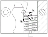
FIG. 10 is a force diagram showing the locked condition of the flask after the flask is closed.
FIG. 11 is a view showing the state of the load applied to the flask when the flask is opened.
In the figure, 1-cope flask, 2-drag flask, 3-closing plate, 4-latch hook guide block, 5-guide post, 6-locking pin, 7-locking block, 8-spring, 9-limit screw and 10-ejector rod.
Detailed Description
The preferred embodiments of the present invention will be described in detail below with reference to the accompanying drawings.
Referring to fig. 1-7, the sand box of the present embodiment is composed of a cope box 1 and a drag box 2, and a latch hook block mechanism is provided between the cope box and the drag box and is engaged with the cope box and the drag box by locking and unlocking the latch hook block mechanism. The two lock hook block mechanisms are symmetrically arranged and are respectively arranged on two opposite side surfaces of the upper sand box and the lower sand box. The other two opposite sides of the cope and drag flasks each form upper and lower rim bosses such that both form gripping recesses 1-1, 2-1.
Each lock hook block mechanism comprises a lock hook guide block 4, a guide pillar 5, a locking pin 6, a locking block 7, a spring 8 and the like, wherein the guide pillar 5 is fixed on the drag box and arranged upwards. The latch hook guide block 4 is fixed to the cope flask and forms a vertical guide hole with two communicated side surfaces, wherein one guide hole corresponds to the guide post 5, i.e. the guide post 5 can movably extend into the guide hole from bottom to top. An upper movable locking block 7 and a lower movable locking block 7 are arranged in the other guide hole, a spring 8 is arranged between the bottom of the locking block 7 and the bottom surface of the guide hole, a limiting screw 9 is fixedly connected to the bottom of the locking block, and the lower end of the limiting screw movably penetrates through the bottom surface of the guide hole to be positioned outside the locking hook guide block. Two side walls at the communication position of the two guide holes of the lock hook guide block form transverse guide holes, a locking pin 6 is arranged between the two transverse guide holes, and the locking pin 6 can horizontally move along the two guide holes. The top of the guide post 5 is inclined towards the side of the locking block, a notch is formed below the inclined surface, the notch also faces towards the side of the locking block, and the notch is matched with the shape of the locking pin which is transversely arranged. The upper part of the locking piece 7 also forms a notch facing the side of the guide post, which fits the profile of the transverse placement of the locking pin and which forms an inclined surface downwards. An external sealing cover closing plate 3 is arranged at the position of the vertical guide hole of the lock hook guide block.
During locking, the ejector rod 10 pushes the locking block 7 to press the spring 8 downwards, when the guide pillar 5 is inserted into the locking hook guide block 4, the conical surface at the top end of the guide pillar 5 extrudes to enable the locking pin 6 to transversely move into the arc-shaped groove of the locking block 7, when the guide pillar 5 is continuously inserted until the groove is tangent to the locking pin groove, the ejector rod 10 resets and moves upwards, the spring releases to push the locking block 7 to move upwards, and the locking pin 6 rebounds and is clamped into the groove of the guide pillar 5 to limit the guide pillar 5.
When the box is opened, the ejector rod 10 vertically presses the locking block 7 downwards, the locking block 7 compresses the spring 8, the arc-shaped groove on the side surface of the locking block 7 descends by a rated height, at the moment, the locking pin 6 is extruded by the groove of the guide pillar 5 when the manipulator lifts the upper sand box, because the horizontal side loses the constraint of the locking block 7, the horizontal component force of the inclined surface of the groove of the guide pillar 5 enables the locking pin 6 to transversely move into the arc-shaped groove of the locking block 7, the guide pillar 5 fixed on the lower sand box is separated from the locking hook block 4 fixed on the upper sand box, the upper sand box and the lower sand box are separated, and at the moment, the spring 8 drives the locking block 7 to reset.
The upper sand box and the lower sand box are locked to form a casting whole, the grabbing cylinder on the side surface of the manipulator resets to push the grippers in the guide pillars to two sides, the right-angle type grabbing hook moves horizontally to leave the lug boss of the upper sand box, then the manipulator lifting cylinder resets to lift the manipulator to be separated from the sand box, and the trolley moving cylinder fixed on the portal frame drives the trolley manipulator to return to a pre-mould station. At this point, the flask after the flask is closed continues to advance on the mold closing conveyor chain to the transfer station.
A fixing device can be arranged at the unpacking position to unlock the box locking mechanism (the box locking mechanism is reversely arranged from the bottom to the top when the cylinder is used).
The force state of the latch block mechanism is analyzed next.
W is the total weight of the sand box
W 1 For sand boxes
W 2 For moulding sand weight
W 3 For each molten iron box weight
Total weight of the casting flask after casting W = W 1 +W 2 +W 3
Locking block gravity G
The radius of the cylinder piston is r
Compressed air pressure p
Cylinder rod pressure Fn = pi r 2 P
The friction force of the locking block is f
Spring coefficient of elasticity N
Pre-tightening force of F t
Compression stroke of L
Shear strength of the locking pin is sigma Scissors
Stress state when closing the box (see fig. 8): thrust F generated by cylinder rod n =πr 2 P,F Bullet =F t + NL when Fn>F Bullet And when the pressure reaches + f-G, the locking block is pressed down. At the moment, the guide column is inserted into the locking hook block, the interaction force of the guide column and the locking pin is Fx, and the locking pin is transversely moved by the horizontal component force Fa = cos alpha Fx. When the guide post is inserted until the groove is tangent to the locking pin groove, the cylinder rod returns, and at the moment, F Bullet >f + G, the spring releases the locking block to move upwards. See fig. 9.
The locking pin is pressed by the extrusion force F of the locking block k ,F k Producing a horizontal component force F d =sinγF k The locking pin is rebounded and clamped into the guide postIn the groove.
Force state at the time of hoisting (see fig. 10): at the moment, the interaction force of the guide pillar and the locking pin is F Combination of Chinese herbs Also producing a horizontal component F Water (W) And a direct component F Hanging device Wherein F is Hanging device =W/2,F Water (W) And F Closing box Acting at an angle theta on the latch hook groove to produce a static friction force F Water (W) tanθ=F Hanging device And the shear force F of the locking pin and the guide pillar in the vertical direction Scissors =F Vertical plate = W/2, the magnitude of the shear force is related to the diameter of the locking pin and the material, the diameter of the locking pin can be deduced (d/2) 2 πσ Scissors =W/2

Force state when opening the box (see fig. 11): cylinder rod producing thrust F n =πr 2 P,F Bullet =F t + NL when Fn>F Bullet And when the pressure reaches + f-G, the locking block is pressed down to release the restraint of the locking pin. At the moment, the lifting hook lifts the cope flask, the instantaneous interaction force of the guide column and the locking pin is F, and the locking pin is transversely moved by the horizontal component force F1= cos beta F. The cylinder rod is returned after the cope and drag flasks are separated, at this time, F Bullet >f + G, the spring releases the locking block to move upwards, and the locking pin is extruded by the locking block to return to the initial state.
Claims (5)
1. A lock hook mechanism of a sand box comprises a cope box and a drag box, wherein the cope box and the drag box are both in a square frame shape, and the cope box and the drag box are detachably assembled to form the sand box; the two lock hook block mechanisms are respectively arranged on two opposite side surfaces of the cope flask and the drag flask;
the lock hook block mechanism comprises a lock hook guide block, a guide pillar, a locking pin, a locking block and an elastic piece, wherein the guide pillar is fixed on the lower sand box and is arranged upwards; the lock hook guide block is fixed on the upper sand box, the lock hook guide block forms two vertical guide holes with communicated side surfaces, the guide pillar can movably extend into one guide hole from bottom to top, the other guide hole is internally provided with an upper movable locking block and a lower movable locking block, and the bottom of the locking block is contacted with the elastic piece; two side walls at the communication position of the two guide holes of the lock hook guide block form transverse guide holes, and a horizontally movable cylindrical locking pin is arranged between the two transverse guide holes; the top of the guide post is a conical surface towards one side of the locking block, a notch is formed below the conical surface, the notch faces one side of the locking block, and the notch is matched with the transverse shape of the locking pin; the upper part of the locking block is also provided with a notch, the notch faces one side of the guide pillar, the notch is matched with the transversely placed shape of the locking pin, and the notch downwards forms an inclined surface facing one side of the guide pillar;
when the locking pin is locked, the locking block is pushed to press down the elastic piece, when the guide pillar is inserted into the locking hook guide block, the conical surface at the top of the guide pillar extrudes to enable the locking pin to transversely move into the notch of the locking block, when the guide pillar is continuously inserted until the notch of the guide pillar is tangent to the notch of the locking pin, the elastic piece releases to push the locking block to move upwards, and the locking pin rebounds to be clamped into the notch of the guide pillar to limit the guide pillar;
when the cope flask is opened, the locking block is pressed downwards vertically, the locking block compresses the elastic piece, the notch of the locking block descends to the rated height, the locking pin is extruded by the notch of the guide pillar when the cope flask is lifted, and because the horizontal side loses the restraint of the locking block, the horizontal component force of the inclined plane at the notch of the guide pillar enables the locking pin to transversely move into the notch of the locking block, and the guide pillar fixed on the drag flask is separated from the lock hook guide block fixed on the cope flask.
2. The lock hook mechanism of the sand box as claimed in claim 1, wherein: the elastic piece is a spring which is arranged between the bottom of the locking block and the bottom surface of the corresponding guide hole.
3. The lock hook mechanism of the sand box as claimed in claim 1 or 2, which is characterized in that: the bottom of the locking block is fixedly connected with a limiting screw, and the lower end of the limiting screw movably penetrates out of the bottom surface of the corresponding guide hole and is positioned outside the locking hook guide block.
4. The lock hook mechanism of the sand box as claimed in claim 1 or 2, wherein: and a sealing plate is covered on the outer part of the lock hook guide block, which is provided with a vertical guide hole.
5. The lock hook mechanism of the sand box as claimed in claim 1, wherein: and the other two opposite side surfaces of the cope flask and the drag flask respectively form an upper edge boss and a lower edge boss, so that a concave part is formed between the upper edge boss and the lower edge boss.
Priority Applications (1)
| Application Number | Priority Date | Filing Date | Title |
|---|---|---|---|
| CN201610246677.2A CN107303599B (en) | 2016-04-18 | 2016-04-18 | Sand box latch hook mechanism |
Applications Claiming Priority (1)
| Application Number | Priority Date | Filing Date | Title |
|---|---|---|---|
| CN201610246677.2A CN107303599B (en) | 2016-04-18 | 2016-04-18 | Sand box latch hook mechanism |
Publications (2)
| Publication Number | Publication Date |
|---|---|
| CN107303599A CN107303599A (en) | 2017-10-31 |
| CN107303599B true CN107303599B (en) | 2022-11-25 |
Family
ID=60152214
Family Applications (1)
| Application Number | Title | Priority Date | Filing Date |
|---|---|---|---|
| CN201610246677.2A Active CN107303599B (en) | 2016-04-18 | 2016-04-18 | Sand box latch hook mechanism |
Country Status (1)
| Country | Link |
|---|---|
| CN (1) | CN107303599B (en) |
Families Citing this family (3)
| Publication number | Priority date | Publication date | Assignee | Title |
|---|---|---|---|---|
| CN109767850B (en) * | 2018-12-21 | 2023-08-25 | 中广核研究院有限公司 | Lower locking device of fuel assembly and using method thereof |
| CN109767851B (en) * | 2018-12-21 | 2023-08-25 | 中广核研究院有限公司 | Lower locking device of fuel assembly and locking and unlocking method thereof |
| CN110296137A (en) * | 2019-07-22 | 2019-10-01 | 南京岳满科技有限公司 | Passenger train axle temperature control device and passenger train with it |
Family Cites Families (11)
| Publication number | Priority date | Publication date | Assignee | Title |
|---|---|---|---|---|
| JP3042662B2 (en) * | 1993-10-18 | 2000-05-15 | 鹿島建設株式会社 | Automatic joining and separating device for earth auger screw shaft |
| US7150310B2 (en) * | 2004-08-31 | 2006-12-19 | Hunter Automated Machinery Corporation | Automated clamping mechanism and mold flask incorporating same |
| JP5532406B2 (en) * | 2010-03-10 | 2014-06-25 | 新東工業株式会社 | Vacuum forming frame |
| CN201735739U (en) * | 2010-06-29 | 2011-02-09 | 山东浩信机械有限公司 | Sand box locking device |
| CN202301329U (en) * | 2011-08-26 | 2012-07-04 | 祝贵佳 | Locking mechanism and lifting rod |
| CN102328033B (en) * | 2011-11-01 | 2013-06-05 | 江苏万工科技集团有限公司 | Locking mechanism for sand mould supporting plate |
| CN103350198A (en) * | 2013-07-15 | 2013-10-16 | 诸城市华欣铸造有限公司 | Foundry sand box locking device |
| CN203580041U (en) * | 2013-10-18 | 2014-05-07 | 日佳力机电工业(昆山)有限公司 | Self-reset side core-pulling mechanism of injection mold |
| CN203737960U (en) * | 2014-02-24 | 2014-07-30 | 什邡永森机械有限公司 | Casting sand box |
| CN204584204U (en) * | 2014-12-30 | 2015-08-26 | 广西科技大学 | A kind of casting mould assembling pressure box fastener |
| CN204799908U (en) * | 2015-07-20 | 2015-11-25 | 宁波永祥铸造有限公司 | Locking mechanism of casting sand box |
-
2016
- 2016-04-18 CN CN201610246677.2A patent/CN107303599B/en active Active
Also Published As
| Publication number | Publication date |
|---|---|
| CN107303599A (en) | 2017-10-31 |
Similar Documents
| Publication | Publication Date | Title |
|---|---|---|
| CN107303599B (en) | Sand box latch hook mechanism | |
| CN203236669U (en) | Inclined guide column lateral parting core-pulling mold | |
| CN202725978U (en) | Airborne casting mould of compressor middle casing | |
| CN207206694U (en) | Building materials are molded moulding box | |
| CN202387938U (en) | Die for secondary core pulling of inclined guide pillar and slide blocks | |
| CN107415166A (en) | A kind of mould bases for being conveniently replaceable die | |
| CN201921994U (en) | Device for preventing upper box of welding sand box in casting from lifting | |
| CN205364415U (en) | Slider constructs with mold machine of jointly loosing core in oblique top | |
| CN207224475U (en) | A kind of mould bases for being conveniently replaceable mode | |
| CN216068377U (en) | Automatic grabbing and clamping jig for transverse manipulator | |
| US2962775A (en) | rekart | |
| CN114012044B (en) | Iron mold box locking device and method for iron mold sand-lined casting pouring roller way | |
| KR100260141B1 (en) | Al- wheel casting device | |
| CN205816749U (en) | Sandbox latch hook mechanism | |
| KR20190031009A (en) | Reaction high forging molding device | |
| CN102069170A (en) | Die mechanism for obliquely pushing parallel push plate out | |
| CN204848965U (en) | Pelletizing press forming treatment facility | |
| CN114833919A (en) | Forming equipment of concrete brick permeates water | |
| CN109940795B (en) | Automatic internal mold loading and demolding device for cable intermediate joint rubber piece | |
| US4791975A (en) | Process of flaskless sand casting | |
| CN212664855U (en) | Sand core forming die for automobile engine connecting piece | |
| CN106804773B (en) | Compressed tea template structure | |
| CN107952875B (en) | Forming machine with overturning demoulding device | |
| CN207448969U (en) | The efficiently injection mould of removal cavity runner system condensate | |
| CN215918838U (en) | Integrated die and stamping equipment |
Legal Events
| Date | Code | Title | Description |
|---|---|---|---|
| PB01 | Publication | ||
| PB01 | Publication | ||
| SE01 | Entry into force of request for substantive examination | ||
| SE01 | Entry into force of request for substantive examination | ||
| GR01 | Patent grant | ||
| GR01 | Patent grant |