CN107234207B - Six mould cold mound machines retooling auxiliary machinery hand systems - Google Patents
Six mould cold mound machines retooling auxiliary machinery hand systems Download PDFInfo
- Publication number
- CN107234207B CN107234207B CN201710406203.4A CN201710406203A CN107234207B CN 107234207 B CN107234207 B CN 107234207B CN 201710406203 A CN201710406203 A CN 201710406203A CN 107234207 B CN107234207 B CN 107234207B
- Authority
- CN
- China
- Prior art keywords
- connecting rod
- arm
- gripper
- guide rail
- clamping
- Prior art date
- Legal status (The legal status is an assumption and is not a legal conclusion. Google has not performed a legal analysis and makes no representation as to the accuracy of the status listed.)
- Active
Links
Images


Classifications
-
- B—PERFORMING OPERATIONS; TRANSPORTING
- B21—MECHANICAL METAL-WORKING WITHOUT ESSENTIALLY REMOVING MATERIAL; PUNCHING METAL
- B21J—FORGING; HAMMERING; PRESSING METAL; RIVETING; FORGE FURNACES
- B21J13/00—Details of machines for forging, pressing, or hammering
- B21J13/08—Accessories for handling work or tools
- B21J13/085—Accessories for handling work or tools handling of tools
Abstract
The invention relates to a six-die cold heading machine die change auxiliary manipulator system. The method is characterized in that: the auxiliary manipulator system comprises a large arm, a small arm, a main gripper, a secondary gripper, a pneumatic wrench, a pneumatic controller and other linkage parts. The large arm is fixed on the cold heading machine through a nut, the circular tube end of the rotary connecting rod is directly sleeved on the middle connecting column to realize the rotary motion of a horizontal plane, and the long connecting rod and the short connecting rod of the large arm realize the swing on a vertical plane; the small arm is linked with the large arm connecting rod through the thrust bearings which are symmetrically arranged, so that the small arm can horizontally rotate relative to the axis of the large arm connecting rod.
Description
Technical Field
The invention relates to a six-die cold heading machine die change auxiliary manipulator system.
Background
At present, with the rapid development of national economy, the social demand for fasteners and special-shaped pieces is increasingly expanding. The fastener and the special-shaped part are basic mechanical elements of national strategy, the cold heading process is a main mode for processing the parts, because the cold machining usually needs dozens of tons of force and hundreds of tons of force, the used die is usually heavier, the structure of the cold heading part is complex, the space for replacing the die is narrow, the labor intensity of manual die replacement is high, other related parts of the whole machine are easily damaged, the replacement period of the die is long, generally more than 2 skilled workers can cooperate for more than half a day, and the assembly precision is influenced by different skill levels of the workers, and the workers are also easily injured. For example, the mass of a single mold used by the DBP206 cold-heading machine exceeds 40kg, the maximum distance between a movable mold and a fixed mold does not exceed 700mm, and the cold-heading machine realizes that the cold-heading action part has a complex structure and more than thousands of component parts. How to realize low cost, high precision, high efficiency and safe die change always troubles the die change work of the cold heading machine. At present, no mechanical production aiming at quick and safe die change of the cold heading machine exists in China, and related patents and thesis achievements are few. For example, an off-line die changing device special for a multi-station cold heading forming machine is disclosed in the journal of equipment, and a die and a cavity are combined into a component to realize one-time die changing. However, this structure requires high machining precision, and large pieces are high in machining cost with high precision, and the precision of the contact surface is easy to be damaged, and the installation precision of the cold heading machine die is less than 2 wires, so that the cold heading machine die is difficult to realize.
Disclosure of Invention
In order to overcome the defects of the technical background, the invention discloses a six-die cold heading machine die change auxiliary manipulator system. Not only can the retooling fast, can also ensure high accuracy and safety. In order to solve the problems, the technical scheme adopted by the invention is as follows: a six-die cold heading machine die change auxiliary manipulator system comprises a large arm arranged on one side of a cold heading machine, a small arm arranged at the upper end of the large arm and with a cantilever end swinging up and down, a main gripper rotating on the horizontal plane and arranged below the cantilever end of the small arm, and a secondary gripper horizontally arranged on the main gripper in a telescopic manner and used for clamping a die; the secondary gripper is positioned above the cold heading machine type cavity.
The large arm comprises a main upright post arranged on the cold heading machine, a middle connecting post arranged on the main upright post, a rotating connecting rod with the lower part rotatably or fixedly arranged at the upper part of the middle connecting post, two rotating shafts arranged in a first U-shaped seat at the top of the rotating connecting rod in parallel, and a large arm long connecting rod and a large arm short connecting rod which are parallel to each other and the root parts of which are sleeved on the corresponding rotating shafts; the lower end of the root of the large-arm long connecting rod and the middle connecting column are respectively provided with a connecting support lug, and a limiting spring is arranged between the two connecting support lugs; the small arm comprises a connecting rod, a small arm main beam horizontally arranged below the connecting rod and a thrust bearing arranged between a lower end shaft of the connecting rod and the small arm main beam; two parallel connecting pin shafts are inserted in the second U-shaped seat of the connecting rod, and the connecting pin shafts are tightly connected with the second U-shaped seat through pin shaft nuts; the head part of the long connecting rod of the large arm and the head part of the short connecting rod of the large arm are respectively sleeved on the opposite connecting pin shafts; two intersection points of the large-arm long connecting rod and the large-arm short connecting rod with the two connecting pin shafts and two intersection points of the large-arm long connecting rod and the large-arm short connecting rod with the two rotating shafts are connected to form a parallelogram structure on a vertical plane; a connecting rotating shaft is arranged at the lower end of the small arm main beam, a thrust bearing is arranged between the connecting rotating shaft and the small arm main beam, a bearing end cover is arranged above the thrust bearing, a rotating shaft fixing nut used for tightly backing the thrust bearing below the bearing end cover is arranged at the upper end of the connecting rotating shaft, and a rotating shaft fixing nut used for tightly backing the thrust bearing is arranged below the lower end shaft of the connecting rod; the connecting rod and the connecting rotating shaft are respectively vertically positioned at the left end and the right end of the small arm main beam, and the connecting rod and the connecting rotating shaft are respectively positioned at the upper side and the lower side of the small arm main beam. A distribution box is arranged on the large arm; a pneumatic wrench is hung on the small arm girder, and a three-hole button box electrically connected with the distribution box is arranged on the small arm girder; and a main gripper pneumatic switch, a secondary gripper pneumatic switch and a pneumatic wrench air source switch are respectively arranged on the three-hole button box. The secondary hand grip comprises a hand grip mounting frame of which the upper part is connected with the connecting rotating shaft; two guide rail supports are arranged at the lower end of the gripper mounting frame, a linear guide rail is horizontally arranged between the two guide rail supports, a linear bearing fixing seat is horizontally arranged on the linear guide rail in a sliding way, L-shaped connecting plates are connected with the two sides of the linear bearing fixing seat through fixing nuts, a rotary clamping cylinder mounting rack is arranged at the lower end of the L-shaped connecting plate, a horizontally arranged rotary clamping cylinder is arranged at one side of the rotary clamping cylinder mounting rack, the rotary clamping cylinder is connected with a cylinder nut and the rotary clamping cylinder mounting rack through a cylinder bolt, a piston rod of the rotary clamping cylinder is connected with a coupler, two coaxial clamping jaw mounting racks in transmission connection with the coupler are arranged at the other side of the rotary clamping cylinder mounting rack, a limiting sleeve is arranged between the two coaxial clamping jaw mounting frames and is connected with the clamping jaw mounting frames through nuts and bolts; at least three second clamping jaws are circumferentially distributed on the clamping jaw mounting frame in an array manner; the at least three second clamping jaws are used for clamping the die; an arc guide rail disc is fixedly arranged between the clamping jaw mounting frame and the clamping jaw mounting frame, a radial bearing is arranged between the arc guide rail disc and an output shaft of the coupler, at least three arc rails are distributed on the arc guide rail disc in a circumferential array mode, and the arc rails are arranged on the arc guide rail disc gradually from the periphery of a circle to the axis along the length direction of the rails; the roots of the second clamping jaws are respectively positioned in the corresponding arc tracks; the main gripper comprises a box body arranged on one side of the gripper mounting frame, at least two linear guide rails horizontally penetrating through the box body, and a bushing arranged in the box body and in contact with the linear guide rails; the two sides of the box body are symmetrically provided with chain plates, the chain plates are vertically provided with two guide grooves, the inner side of each chain plate is provided with two V-shaped first clamping jaws, the back surfaces of the first clamping jaws are connected with bolts penetrating through the corresponding guide grooves, and the outer sides of the chain plates are provided with nuts and gaskets connected with the bolts; a linear bearing is arranged between the linear guide rail and the chain plates, a cylindrical shaft parallel to the linear guide rail is arranged between the two chain plates, the linear bearing sleeved on the cylindrical shaft is arranged in the box body, and an air cylinder parallel to the air cylinder guide rod and the linear guide rail is arranged on one side of the box body; the two cylinders are arranged in opposite directions, and a cylinder guide rod of each cylinder is connected with the corresponding chain plate through a fixing nut; the V-shaped first clamping jaw is used for clamping a die; the axial center line of the V-shaped first clamping jaw is coaxial with the axial center lines of the three second clamping jaws. And a clamping jaw limiting strip is arranged on one side of the first clamping jaw. The grip mounting frame is provided with a main handle. And a secondary handle is arranged on one side of the rotary clamping cylinder mounting frame.
When the cold heading machine is used for changing the mold, the auxiliary mechanical arm system can be used for quickly, safely and reliably changing the mold of the cold heading machine, so that the mold changing cost is reduced, and the safety and the efficiency of mold changing are improved. The circular tube end of the rotary connecting rod is directly sleeved on the middle connecting column, the structure is simple and reliable, the connecting mode of the large arm and the small arm can ensure that the axis of the mold is always kept in a horizontal state, the assembly is convenient, the linear clamping jaw and the rotary clamping jaw are used in a special clamp designed for clamping and assembling the mold, the clamping strength of a heavy mold can be ensured, the installation stroke requirement of the mold can be met, the tightness of a quick screw nut can be realized by introducing a pneumatic wrench, the pretightening force of the quick screw nut can be controlled, a plurality of thrust bearings are used, the rotation of an auxiliary mechanical arm can be smoothly realized, the assembly size of the arm can be reduced, and the lifting of the large arm of the mechanical arm can be controlled by using a limiting spring.
Drawings
Fig. 1 is a schematic structural view of a main gripper disclosed by the invention.
FIG. 2 is a schematic view of a sub-gripper according to the present invention.
FIG. 3 is a schematic view of the forearm hand according to the present invention.
FIG. 4 is a schematic view of the structure of the forearm hand of the present invention.
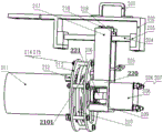
FIG. 5 is a schematic structural view of a mold changing auxiliary manipulator system of the six-mold cold heading machine of the invention.
FIG. 6 is a rear view of the clamping mold according to the present invention.
Fig. 7 is a schematic view of another perspective structure of the sub-gripper according to the present invention.
Fig. 8 is a schematic view of another perspective structure of the forearm hand of the present invention.
Detailed Description
As shown in fig. 1 to 8, the six-mold cold heading machine mold changing auxiliary manipulator system of the present embodiment includes a large arm 400 disposed at one side of the cold heading machine, a small arm 300 disposed at the upper end of the large arm 400 and having its cantilever end swinging up and down, a main gripper 100 rotating on the horizontal plane and disposed below the cantilever end of the small arm 300, and a sub gripper 200 disposed on the main gripper 100 and extending horizontally and used for clamping a mold 211, as shown in fig. 1; the secondary gripper 200 is located above the cold heading machine cavity 001. The large arm 400 comprises a main upright 408 arranged on the cold heading machine, a middle connecting column 407 arranged on the main upright 408, a rotating connecting rod 403 with the lower part rotatably or fixedly arranged at the upper part of the middle connecting column 407, two rotating shafts arranged in a first U-shaped seat at the top of the rotating connecting rod 403 in parallel, and a large arm long connecting rod 401 and a large arm short connecting rod 402 which are parallel to each other and the root parts of which are sleeved on the corresponding rotating shafts; the large-arm long connecting rod 401 is positioned right above the large-arm short connecting rod 402, the root of the large-arm long connecting rod 401 is exposed out of the first U-shaped seat, the lower end of the root of the large-arm long connecting rod 401 and the middle connecting column 407 are respectively provided with a connecting support lug 406, and a limiting spring 404 is arranged between the two connecting support lugs 406; the small arm 300 comprises a connecting rod 301, a small arm girder 306 horizontally arranged below the connecting rod 301, and a thrust bearing 304 arranged between the lower end shaft of the connecting rod 301 and the small arm girder 306; two parallel connecting pin shafts 302 are inserted into the second U-shaped seat of the connecting rod 301, and the connecting pin shafts 302 are tightly connected with the second U-shaped seat through pin shaft nuts 303; the head part of the large arm long connecting rod 401 and the head part of the large arm short connecting rod 402 are respectively sleeved on the opposite connecting pin shafts 302; two intersection points of the large-arm long connecting rod 401 and the large-arm short connecting rod 402 with the two connecting pin shafts 302 and two intersection points of the large-arm long connecting rod 401 and the large-arm short connecting rod 402 with the two rotating shafts are connected to form a parallelogram structure on a vertical plane; a connecting rotating shaft 312 is arranged at the lower end of the small arm main beam 306, a thrust bearing is arranged between the connecting rotating shaft 312 and the small arm main beam 306, a bearing end cover 313 is arranged above the thrust bearing, a rotating shaft fixing nut 314 for tightly backing the thrust bearing below the bearing end cover 313 is arranged at the upper end of the connecting rotating shaft 312, and a rotating shaft fixing nut 315 for tightly backing the thrust bearing 304 is arranged below the lower end shaft of the connecting rod 301; the connecting rod 301 and the connecting rotating shaft 312 are respectively vertically located at the left end and the right end of the small arm main beam 306, and the connecting rod 301 and the connecting rotating shaft 312 are respectively located at the upper side and the lower side of the small arm main beam 306. A distribution box 405 is provided on the boom 400; a pneumatic wrench 305 is hung on the small arm girder 306, and a three-hole button box 307 electrically connected with a distribution box 405 is arranged on the small arm girder 306; a main gripper pneumatic switch 308, a sub gripper pneumatic switch 309, and a pneumatic wrench air supply switch 310 are provided on the three-hole button box 307, respectively. The sub-hand grip 200 includes a grip mounting bracket 202 having an upper portion connected to the connection rotation shaft 312; two guide rail supports 203 are arranged at the lower end of the gripper mounting frame 202, a linear guide rail 204 is horizontally arranged between the two guide rail supports 203, a linear bearing fixing seat 219 is horizontally arranged at the linear guide rail 204 in a sliding manner, an L-shaped connecting plate 217 is connected at two sides of the linear bearing fixing seat 219 through fixing nuts 218, a rotary clamping cylinder mounting frame 220 is arranged at the lower end of the L-shaped connecting plate 217, a rotary clamping cylinder 208 horizontally arranged is arranged at one side of the rotary clamping cylinder mounting frame 220, the rotary clamping cylinder 208 is connected with a cylinder nut 207 and the rotary clamping cylinder mounting frame 220 through a cylinder bolt 206, a piston rod of the rotary clamping cylinder 208 is connected with a coupler 221, two coaxial gripper mounting frames 213 in transmission connection with the coupler 221 are arranged at the other side of the rotary clamping cylinder mounting frame 220, a limiting sleeve 216 is, the limit sleeve 216 is connected with the jaw mounting bracket 213 through a nut 214 and a bolt 215; at least three second clamping jaws 212 are distributed on the clamping jaw mounting frame 213 in a circumferential array; at least three second clamping jaws 212 for clamping the die 211; an arc guide rail disc 210 is fixedly arranged between the clamping jaw mounting frame 213 and the clamping jaw mounting frame 213, a radial bearing 209 is arranged between the arc guide rail disc 210 and an output shaft of the coupler 221, at least three arc rails 2101 are circumferentially distributed on the arc guide rail disc 210 in an array manner, and the arc rails 2101 are arranged on the arc guide rail disc 210 gradually along the length direction of the rails from the periphery to the axis; the roots of the second jaws 212 are respectively located in the corresponding arc rails 2101; the main gripper 100 comprises a box body 109 arranged on one side of the gripper mounting frame 202, at least two linear guide rails 105 horizontally penetrating through the box body 109, and a bushing 107 arranged in the box body 109 and contacted with the linear guide rails 105; the two sides of the box body 109 are symmetrically provided with chain plates 101, the chain plates 101 are vertically provided with two guide grooves, the inner side of each chain plate 101 is provided with two V-shaped first clamping jaws 114, the back surfaces of the first clamping jaws 114 are connected with bolts 104 penetrating through the corresponding guide grooves, and the outer sides of the chain plates 101 are provided with nuts 102 and gaskets 103 connected with the bolts 104; a linear bearing 106 is arranged between the linear guide rail 105 and the chain plates 101, a cylindrical shaft parallel to the linear guide rail 105 is arranged between the two chain plates 101, a linear bearing 108 sleeved on the cylindrical shaft is arranged in the box body 109, and a cylinder 110 parallel to the linear guide rail 105 and a cylinder guide rod 111 is arranged on one side of the box body 109; the two cylinders 110 are arranged in opposite directions, and a cylinder guide rod 111 of each cylinder 110 is connected with the corresponding chain plate 101 through a fixing nut 112; the first clamping jaw 114 of the V-shape is used for clamping the die 211; the V-shaped first jaw 114 is located on an axial centerline that is coaxial with the axial centerline of the three second jaws 212. A jaw stop 113 is provided on one side of the first jaw 114. A main handle 201 is provided on the grip mounting bracket 202. A sub-handle 205 is provided at one side of the rotary clamping cylinder mounting bracket 220.
As shown in fig. 1-8, the present invention mainly includes a main gripper 100, a sub gripper 200, a small arm 300, a large arm 400, a pneumatic wrench 305, a pneumatic controller, etc., as detailed descriptions. One end of the large arm 400 is connected with the cold heading machine, the other end of the large arm 400 is connected with the small arm 300, the lower end of the other end of the small arm 300 is connected with the secondary hand grab 200, and the main hand grab 100 is installed on the secondary hand grab installation frame 202. The pneumatic controller is mounted on the forearm main beam 306, and the pneumatic wrench 305 is placed on the side of the forearm main beam 306.
The main gripper 100 comprises a chain plate 101, a horizontally arranged linear guide rail 105, a linear bearing 106, a bushing 107, a linear bearing 108, a box 109, an air cylinder 110, an air cylinder guide rod 111, a guide rod fixing nut 112, a gripper limiting bar 113 and a first gripper 114. The first clamping jaw 114 is connected with a chain plate 101 through a nut 102, a gasket 103 and a bolt 104, the chain plate 101 is connected with a linear guide rail 105 through a linear bearing 106, and the chain plate 101 is symmetrically arranged on the front side and the rear side of the box body 109; the linear guide 105 is connected with a box 109 through a bushing 107; the cylinders 110 are symmetrically arranged at the left side and the right side of the box body 109, the chain plates 101 are connected with the cylinders 109 through cylinder guide rods 111 and guide rod fixing nuts 112, and when the cylinders 110 extend and retract, the front and rear chain plates 101 of the box body 109 are driven to synchronously move.
Wherein the position of the clamping jaw on the chain plate can be adjusted within a certain range; the clamping jaw limiting strip 113 is connected with the clamping jaw through a plurality of nuts, a plurality of gaskets and a plurality of bolts, and one side surface of the clamping jaw limiting strip 113 is contacted with one side surface of the clamping jaw.
When the mold is clamped, the relative positions of the first clamping jaw 114 and the mold 211 are adjusted firstly, so that the symmetry line of the first clamping jaw 114 is coincided with the axis of the mold 211, the main gripper pneumatic switch 308 is pressed, the cylinders 110 are symmetrically arranged to drive the cylinder guide rods 111 to do contraction motion, the connecting chain plates 101 do opposite motion along the linear guide rails 105, the distance between the two connecting plates 101 is reduced, and the first clamping jaw 114 is connected to clamp the mold 211. When the mold is released, the pneumatic switch 308 of the main gripper is pressed, the symmetrically arranged cylinders 110 drive the cylinder guide rods 111 to perform stretching motion, the linking plate 101 performs reverse motion along the linear guide rail 105, the distance between the two linking plates 101 is increased, and the first clamping jaw 114 is linked to release the mold 211.
The secondary hand grip 200 comprises a main handle 201, a hand grip mounting frame 202, a guide rail support 203, a linear guide rail 204, a secondary handle 205, a cylinder bolt 206, a cylinder nut 207, a rotary clamping cylinder 208, a radial bearing 209, an arc guide rail disc 210, a second clamping jaw 212, a clamping jaw mounting frame 213, a nut 214, a bolt 215, a limiting sleeve 216, an L-shaped connecting plate 217, a fixing nut 218 and a linear bearing fixing seat 219. Main handle 201 is connected with tongs mounting bracket 202, rail support 203 symmetry is installed on tongs mounting bracket 202, linear guide 204 and rail support 203 interference fit, L type connecting plate 217 slides at linear guide 204 through linear bearing fixing base 219, secondary handle 205 welds on L type connecting plate 217, rotary clamping cylinder mounting bracket 220 and L type connecting plate 217 welding, the circular arc track of circular arc guide rail dish 210 is tangent with the face of cylinder of second clamping jaw 212, clamping jaw mounting bracket 213 is connected with rotary clamping cylinder 208 through spacing sleeve 216, second clamping jaw 212 and clamping jaw mounting bracket 213 remove vice clearance fit.
The secondary gripper is welded with the connecting rotating shaft through the gripper mounting frame, and the main handle is connected with the gripper mounting frame through a bolt; the linear guide rails are axially matched with the linear bearing fixing seats; the linear bearing fixing seat is connected with a plurality of L-shaped connecting plates through a plurality of fixing nuts, wherein the plurality of L-shaped connecting plates are symmetrically arranged on two sides of the linear bearing fixing seat, and the plurality of L-shaped connecting plates are welded with the rotary clamping cylinder mounting frame; the rotary clamping cylinder is connected with the rotary clamping cylinder frame through a plurality of nuts and a plurality of bolts; the arc guide rail disc is connected with the rotary clamping cylinder frame through a radial bearing and is connected with the rotary clamping cylinder through a coupler; the clamping jaw mounting frame is connected with the rotary clamping cylinder frame through a plurality of nuts, a plurality of bolts and a plurality of limiting sleeves, wherein the limiting sleeves are arranged at equal intervals on the circumference; the shoulder planes of the clamping jaws are in clearance fit with the linear rails on the clamping jaw mounting frame, and the circumferences of the clamping jaws are arranged at equal intervals.
The rotary clamping cylinder mounting frame 220 is welded with the L-shaped connecting plate 217, the rotary clamping cylinder 208 is mounted on the rotary clamping cylinder mounting frame 220, the arc guide rail disc 210 is connected with the rotary clamping cylinder 208 through a shaft coupling 221 in a rotating mode, an arc rail 2101 of the arc guide rail disc 210 is internally tangent to the root cylindrical guide end of the second clamping jaw 212, the clamping jaw mounting frame 213 is connected with the rotary clamping cylinder 208 through a limiting sleeve 216, and the second clamping jaw 212 is in clearance fit with the moving pair of the clamping jaw mounting frame 213. The cylindrical guide end of the second jaw 212 moves within the circular arc track 2101 toward or away from the axis of the rotary clamping cylinder 208.
When the mold is clamped, after the main gripper 100 clamps the mold 211, the second gripper 212 and the mold 211 are horizontally opposite to each other at a proper clamping position by pulling the secondary handle 205, the secondary gripper pneumatic switch 309 is pressed, the rotary clamping cylinder 208 rotates anticlockwise, the circular arc guide rail disc 210 is driven by the coupler 221 to rotate in a fixed axis manner, and therefore the second gripper 212 is driven to perform centripetal contraction movement along the straight track of the gripper mounting frame 213, and the mold is clamped.
When the mold is released, after the main gripper 100 releases the mold 211, the pneumatic switch 309 of the secondary gripper is pressed, the rotating clamp releasing cylinder 208 rotates clockwise, the circular arc guide rail disc 210 is driven by the coupler 221 to rotate in a fixed shaft manner, the second gripper 212 is driven to perform outward expansion movement along the straight rail of the gripper mounting frame 213, the mold is released, and then the secondary gripper is pulled to a horizontal relative proper distance by pulling the secondary handle 205.
The small arm 300 comprises a connecting rod 301, a connecting pin shaft 302, a pin shaft nut 303, a thrust bearing 304, a small arm main beam 306, a connecting rotating shaft 312, a bearing end cover 313 and rotating shaft fixing nuts 314 and 315. One side of the connecting rod 301 is connected with a plurality of connecting pin shafts 302, the lower end shaft of the connecting rod 301 is connected with the small arm girder 306 through a thrust bearing 304, a thrust bearing, a bearing end cover, a rotating shaft fixing nut 314, a rotating shaft fixing nut 315 and a pin shaft nut 303, the upper plane of the small arm girder 306 is always kept perpendicular to the axis of the connecting shaft of the connecting rod 301 in the moving process, and the connecting rotating shaft 312 is connected with the small arm girder 306 through the rotating shaft fixing nut 314, the thrust bearing, the bearing end cover 313 and the small arm girder 306; the axis of the connecting rotating shaft 312 is always vertical to the upper plane of the small arm main beam 306, so that the axis of the mold is always kept parallel to the upper plane of the small arm main beam 306 in a clamping state, the bearing end cover 313 and the pin shaft nut 303 are matched for use, and the height difference between the mold and the small arm main beam 306 is always controlled to be a fixed value.
In the process of realizing the space transfer of the mold, the rotating handle is pulled to move under the traction of the main handle 201, so that the connecting rotating shaft 312 is pulled to do circular motion, and meanwhile, the small-arm main beam is pulled to do space motion.
Furthermore, the small arm is connected to the large arm through a connecting rod, a plurality of connecting pin shafts and a plurality of pin shaft nuts; the other side of the connecting rod is connected with the small arm main beam through a plurality of thrust bearings, bearing end covers and rotating shaft fixing nuts, wherein the thrust bearings are symmetrically arranged on two end faces of a matching shaft of the small arm main beam to realize the circular horizontal motion of the small arm main beam around the shaft end of the connecting rod, and the vertical height of the small arm main beam relative to the connecting rod is limited by the matching use of the bearing end covers and the rotating shaft fixing nuts; the thrust bearing, the bearing end cover and the rotating shaft fixing nut at the other end of the small arm main beam are connected with the connecting rotating shaft, so that the connecting rotating shaft can horizontally move around the circumference of the small arm main beam, and the vertical height of the connecting rotating shaft relative to the small arm main beam is limited by the matching of the bearing end cover and the rotating shaft fixing nut; the connecting rotating shaft is welded with the gripper mounting frame.
The large arm 400 comprises a large arm long connecting rod 401, a large arm short connecting rod 402, a rotating connecting rod 403, a limiting spring 404, a distribution box 405, a connecting lug 406, an intermediate connecting column 407 and a main upright 408.
One end of the large arm 400 is connected with the small arm 300, the other end of the small arm 300 is connected with the secondary hand grip 200, and the primary hand grip is mounted on the secondary hand grip mounting frame. In the moving process, the supply and the disconnection of the air source are realized by pressing different pneumatic switches, the large-distance space movement of the manipulator is realized by the traction movement of the main handle, and the loading and the pulling out of the die cavity are realized by the traction movement of the secondary handle.
The main upright 408 is connected with the cold heading machine through a bolt, the main upright 408 is welded with the middle connecting column 407 coaxially, the rotary connecting rod 403 is sleeved on the middle connecting column 407 coaxially, the large-arm long connecting rod 401 and the large-arm short connecting rod 402 are connected with the rotary connecting rod 403 through the connecting pin shaft 302 and the pin shaft nut 303, and the limiting spring 404 is connected with the large-arm long connecting rod 401 and the rotary connecting rod 403. Under the action of the traction movement of the small arm 300, the large arm 400 performs circular movement around the axis of the middle connecting column 407 and swings around the axis of the connecting pin shaft 302, and the swing angle of the large arm 400 is limited by the limiting spring 404.
The pneumatic wrench is connected with a pneumatic wrench air source switch through an air inlet pipeline. When the pneumatic wrench is idle, one side face of the small arm main beam is placed on the containing frame.
The pneumatic controller comprises a three-hole button box, a main gripper pneumatic switch, a secondary gripper pneumatic switch, a pneumatic wrench air source switch and a plurality of other pneumatic elements. The main gripper pneumatic switch is connected with the main gripper cylinder through an air inlet pipeline; the secondary gripper pneumatic switch is connected with the rotary clamping cylinder through an air inlet pipeline; the air source switch of the pneumatic wrench is connected with the pneumatic wrench through an air inlet pipeline; the three-hole button box is connected with one end of the small arm main beam through a bolt
Cold heading machine die change process: the method comprises two steps, wherein the first step is to take down a mould on a cold heading machine and place the mould on one side, the second step is to load a standby mould into the cold heading machine, and the specific operation flow is as follows:
firstly, taking down the die from the cold heading machine. The pneumatic wrench 305 is taken down from one side of the small-arm main beam 306, the pneumatic wrench air source switch 310 is pressed, the set screw used for fixing the mold on the mold cavity of the cold heading machine is unscrewed for a proper stroke by the pneumatic wrench 305, the mold limit block and the limit block set screw are unscrewed and taken away, and the pneumatic wrench 305 is placed on one side of the small-arm main beam 306. The secondary gripper 200 is pulled to a proper position by pulling the main handle 201, the secondary gripper 205 is used for fine adjustment of a proper clamping distance between the second clamping jaw 212 and the mold 211, the secondary gripper pneumatic switch 309 is pressed, the clamping cylinder 208 is rotated to drive the circular arc guide rail disc 210 to do anticlockwise circular motion, the second clamping jaw 212 is pulled to do centripetal contraction motion along the straight rail of the gripper mounting frame 213, so that the mold 211 is clamped, the secondary gripper 205 is pulled to do straight line motion, most of the mold is pulled out of the cold heading machine cavity, the main gripper pneumatic switch 308 is pressed, the symmetrically arranged cylinders 110 drive the cylinder guide rods 111 to do contraction motion firstly, the connecting chain plates 101 do opposite motion along the straight rail 105, the distance between the two connecting plates 101 is reduced, the connecting clamping jaw 114 clamps the mold 211, the mold is completely pulled out of the cold heading machine cavity 001, the main handle 201 is pulled to transfer the mold to a containing frame, the main gripper pneumatic switch 308 is pressed, the symmetrically arranged cylinders 110 drive the cylinder guide rods 111 to do stretching motion, the connecting chain plates 101 do reverse motion along the linear guide rails 105, the distance between the two connecting plates 101 is increased, and therefore the first clamping jaws 114 are connected to release the die 211. After the main gripper 100 loosens the mold 211, the pneumatic switch 309 of the secondary gripper is pressed, the rotating clamp loosening cylinder 208 rotates clockwise, the circular arc guide rail disc 210 is driven by the coupler 221 to rotate in a fixed shaft mode, the second gripper 212 is driven to do outward expansion movement along the straight rail of the gripper mounting frame 213, the mold is loosened, and then the secondary gripper is pulled to a horizontal position by pulling the secondary handle 205 to a relatively proper distance, so that the mask taking-off action is completed.
Secondly, the main gripper 100 is drawn to a proper position by drawing the main handle 201, the pneumatic switch 308 of the main gripper is pressed, the first clamping jaw 114 is drawn to clamp the mould 211, the proper clamping distance between the second clamping jaw 212 and the mould 211 is finely adjusted by the secondary gripper 205, the pneumatic switch 309 of the secondary gripper is pressed, so that the mould 211 is clamped, the main handle 201 is drawn to transfer the mould to a proper distance from the cold heading machine cavity, the space position of the mould 211 is adjusted to enable the axis to be coincident with the axis of the cavity, the main handle 201 is slowly drawn to partially load the mould into the cold heading machine cavity, the pneumatic switch 308 of the main gripper is drawn to release the mould 211 by the first clamping jaw 114, the secondary gripper 205 is drawn to do linear motion, the mould is loaded into the cold heading machine cavity for a proper distance, the pneumatic switch 309 of the secondary gripper is pressed to release the mould 211, then the secondary gripper is drawn to a proper horizontal distance by drawing the secondary gripper 205, the pneumatic wrench 305 is pressed from one side of the small-arm main beam, the air source switch 310 of the pneumatic wrench is pressed, the set screw for fixing the mold on the mold cavity of the cold heading machine is screwed for a proper stroke by the pneumatic wrench 305, the mold limiting block and the limiting block set screw are unscrewed and installed into the cold heading machine, and the pneumatic wrench 305 is placed on one side of the small-arm main beam 306 to complete the mold assembling action.
Claims (6)
1. The utility model provides a six mould cold mound machines retooling mechanical arm system which characterized in that: the device comprises a large arm (400) arranged on one side of a cold heading machine, a small arm (300) arranged at the upper end of the large arm (400) and with a cantilever end swinging up and down, a main gripper (100) rotating on the horizontal plane and arranged below the cantilever end of the small arm (300), and a secondary gripper (200) horizontally arranged on the main gripper (100) in a telescopic manner and used for clamping a mold (211); the secondary gripper (200) is positioned above a cold heading machine cavity (001), and the large arm (400) comprises a main upright post (408) arranged on the cold heading machine, a middle connecting post (407) arranged on the main upright post (408), a rotating connecting rod (403) with the lower part rotatably or fixedly arranged on the upper part of the middle connecting post (407), two rotating shafts arranged in a first U-shaped seat at the top of the rotating connecting rod (403) in parallel, and a large arm long connecting rod (401) and a large arm short connecting rod (402) which are parallel to each other and the roots of which are sleeved on the corresponding rotating shafts;
the large-arm long connecting rod (401) is positioned right above the large-arm short connecting rod (402), the root of the large-arm long connecting rod (401) is exposed out of the first U-shaped seat, the lower end of the root of the large-arm long connecting rod (401) and the middle connecting column (407) are respectively provided with a connecting support lug (406), and a limiting spring (404) is arranged between the two connecting support lugs (406);
the small arm (300) comprises a connecting rod (301), a small arm main beam (306) horizontally arranged below the connecting rod (301), and a thrust bearing (304) arranged between the lower end shaft of the connecting rod (301) and the small arm main beam (306);
two parallel connecting pin shafts (302) are inserted in the second U-shaped seat of the connecting rod (301), and the connecting pin shafts (302) are tightly connected with the second U-shaped seat through pin shaft nuts (303); the head part of the large arm long connecting rod (401) and the head part of the large arm short connecting rod (402) are respectively sleeved on the opposite connecting pin shafts (302);
two intersection points of the large-arm long connecting rod (401) and the large-arm short connecting rod (402) and the two connecting pin shafts (302) and two intersection points of the large-arm long connecting rod (401) and the large-arm short connecting rod (402) and the two rotating shafts are connected, and the four intersection points are connected to form a parallelogram structure on a vertical plane;
a connecting rotating shaft (312) is arranged at the lower end of the small arm main beam (306), a thrust bearing is arranged between the connecting rotating shaft (312) and the small arm main beam (306), a bearing end cover (313) is arranged above the thrust bearing, a rotating shaft fixing nut (314) for backing up the thrust bearing below the bearing end cover (313) is arranged at the upper end of the connecting rotating shaft (312), and a rotating shaft fixing nut (315) for backing up the thrust bearing (304) is arranged below the lower end shaft of the connecting rod (301);
the connecting rod (301) and the connecting rotating shaft (312) are respectively vertically positioned at the left end and the right end of the small arm main beam (306), and the connecting rod (301) and the connecting rotating shaft (312) are respectively positioned at the upper side and the lower side of the small arm main beam (306).
2. The six-die cold heading machine die change auxiliary manipulator system according to claim 1, wherein a distribution box (405) is arranged on the large arm (400); a pneumatic wrench (305) is hung on the small-arm main beam (306), and a three-hole button box (307) electrically connected with the distribution box (405) is arranged on the small-arm main beam (306); a main gripper pneumatic switch (308), a secondary gripper pneumatic switch (309) and a pneumatic wrench air source switch (310) are respectively arranged on the three-hole button box (307).
3. The auxiliary manipulator system for die change of the six-die cold heading machine according to claim 1, wherein the secondary hand grip (200) comprises a hand grip mounting frame (202) with the upper part connected with the connecting rotating shaft (312); two guide rail supports (203) are arranged at the lower end of the gripper mounting frame (202), a linear guide rail (204) is horizontally arranged between the two guide rail supports (203), a linear bearing fixing seat (219) is horizontally arranged on the linear guide rail (204) in a sliding manner, L-shaped connecting plates (217) are connected to two sides of the linear bearing fixing seat (219) through fixing nuts (218), a rotary clamping cylinder mounting frame (220) is arranged at the lower end of the L-shaped connecting plate (217), a rotary clamping cylinder (208) which is horizontally arranged is arranged on one side of the rotary clamping cylinder mounting frame (220), the rotary clamping cylinder (208) is connected with a cylinder nut (207) and the rotary clamping cylinder mounting frame (220) through a cylinder bolt (206), a piston rod of the rotary clamping cylinder (208) is connected with a coupler (221), two coaxial gripper mounting frames (213) which are in transmission connection with the coupler (221) are arranged on the, a limiting sleeve (216) is arranged between the two coaxial clamping jaw mounting frames (213), and the limiting sleeve (216) is connected with the clamping jaw mounting frames (213) through nuts (214) and bolts (215); at least three second clamping jaws (212) are distributed on the clamping jaw mounting frame (213) in a circumferential array; at least three second clamping jaws (212) for clamping the die (211);
an arc guide rail disc (210) is fixedly arranged between the clamping jaw mounting frame (213) and the clamping jaw mounting frame (213), a radial bearing (209) is arranged between the arc guide rail disc (210) and an output shaft of the coupler (221), at least three arc rails (2101) are distributed on the arc guide rail disc (210) in a circumferential array manner, and the arc rails (2101) are arranged on the arc guide rail disc (210) gradually along the length direction of the rails from the periphery of a circle to the axis; the roots of the second clamping jaws (212) are respectively positioned in the corresponding arc tracks (2101);
the main gripper (100) comprises a box body (109) arranged on one side of the gripper mounting frame (202), at least two linear guide rails (105) horizontally penetrating through the box body (109), and a bushing (107) arranged in the box body (109) and contacted with the linear guide rails (105); the chain plates (101) are symmetrically arranged on two sides of the box body (109), two guide grooves are vertically arranged on the chain plates (101), two V-shaped first clamping jaws (114) are arranged on the inner side of each chain plate (101), bolts (104) penetrating through the corresponding guide grooves are connected to the back surfaces of the first clamping jaws (114), and nuts (102) and gaskets (103) connected with the bolts (104) are arranged on the outer sides of the chain plates (101); a linear bearing (106) is arranged between the linear guide rail (105) and the chain plates (101), a cylindrical shaft parallel to the linear guide rail (105) is arranged between the two chain plates (101), a linear bearing (108) sleeved on the cylindrical shaft is arranged in the box body (109), and a cylinder (110) parallel to the cylinder guide rod (111) and the linear guide rail (105) is arranged on one side of the box body (109); the two cylinders (110) are arranged in opposite directions, and a cylinder guide rod (111) of each cylinder (110) is connected with the corresponding chain plate (101) through a fixing nut (112);
the V-shaped first clamping jaw (114) is used for clamping a die (211);
the axial center line of the V-shaped first clamping jaw (114) is coaxial with the axial center lines of the three second clamping jaws (212).
4. The auxiliary mechanical arm system for die change of the six-die cold heading machine according to claim 3, wherein a clamping jaw limit strip (113) is arranged on one side of the first clamping jaw (114).
5. The six-die cold heading machine die change auxiliary manipulator system according to claim 3, wherein a main handle (201) is arranged on the gripper mounting frame (202).
6. The auxiliary robot system for mold change of the six-mold cold heading machine according to claim 5, wherein a secondary handle (205) is provided at one side of the rotary clamping cylinder mounting frame (220).
Priority Applications (1)
| Application Number | Priority Date | Filing Date | Title |
|---|---|---|---|
| CN201710406203.4A CN107234207B (en) | 2017-06-02 | 2017-06-02 | Six mould cold mound machines retooling auxiliary machinery hand systems |
Applications Claiming Priority (1)
| Application Number | Priority Date | Filing Date | Title |
|---|---|---|---|
| CN201710406203.4A CN107234207B (en) | 2017-06-02 | 2017-06-02 | Six mould cold mound machines retooling auxiliary machinery hand systems |
Publications (2)
| Publication Number | Publication Date |
|---|---|
| CN107234207A CN107234207A (en) | 2017-10-10 |
| CN107234207B true CN107234207B (en) | 2020-01-14 |
Family
ID=59984647
Family Applications (1)
| Application Number | Title | Priority Date | Filing Date |
|---|---|---|---|
| CN201710406203.4A Active CN107234207B (en) | 2017-06-02 | 2017-06-02 | Six mould cold mound machines retooling auxiliary machinery hand systems |
Country Status (1)
| Country | Link |
|---|---|
| CN (1) | CN107234207B (en) |
Families Citing this family (2)
| Publication number | Priority date | Publication date | Assignee | Title |
|---|---|---|---|---|
| CN110154302B (en) * | 2018-04-12 | 2024-01-09 | 淮阴师范学院 | Automatic change hot briquetting machine of removable mould |
| CN114888786A (en) * | 2022-07-13 | 2022-08-12 | 江苏派屹锋智能科技有限公司 | Mechanical positioning absolute coordinate axis industrial mechanical hand |
Citations (6)
| Publication number | Priority date | Publication date | Assignee | Title |
|---|---|---|---|---|
| JPH11886A (en) * | 1997-06-10 | 1999-01-06 | Mitsubishi Nagasaki Mach Co Ltd | Clamping device for forging manipulator |
| JP2001105118A (en) * | 1999-10-12 | 2001-04-17 | Toshiba Mach Co Ltd | Chucking structure of forged product |
| CN103402735A (en) * | 2011-03-08 | 2013-11-20 | 西德尔合作公司 | System for aiding in the replacement of a mould of a molding unit of a machine for manufacturing containers |
| CN203495117U (en) * | 2013-09-17 | 2014-03-26 | 宁波腾工精密机械制造有限公司 | Semi-automatic die change assisting mechanical arm of cold header |
| CN204136065U (en) * | 2014-08-21 | 2015-02-04 | 中山市乾润精密钢球制造有限公司 | Cold headers manipulator |
| CN206779365U (en) * | 2017-06-02 | 2017-12-22 | 温州大学 | Six mould Cold headers change the mold aided arm prosthesis system |
-
2017
- 2017-06-02 CN CN201710406203.4A patent/CN107234207B/en active Active
Patent Citations (6)
| Publication number | Priority date | Publication date | Assignee | Title |
|---|---|---|---|---|
| JPH11886A (en) * | 1997-06-10 | 1999-01-06 | Mitsubishi Nagasaki Mach Co Ltd | Clamping device for forging manipulator |
| JP2001105118A (en) * | 1999-10-12 | 2001-04-17 | Toshiba Mach Co Ltd | Chucking structure of forged product |
| CN103402735A (en) * | 2011-03-08 | 2013-11-20 | 西德尔合作公司 | System for aiding in the replacement of a mould of a molding unit of a machine for manufacturing containers |
| CN203495117U (en) * | 2013-09-17 | 2014-03-26 | 宁波腾工精密机械制造有限公司 | Semi-automatic die change assisting mechanical arm of cold header |
| CN204136065U (en) * | 2014-08-21 | 2015-02-04 | 中山市乾润精密钢球制造有限公司 | Cold headers manipulator |
| CN206779365U (en) * | 2017-06-02 | 2017-12-22 | 温州大学 | Six mould Cold headers change the mold aided arm prosthesis system |
Also Published As
| Publication number | Publication date |
|---|---|
| CN107234207A (en) | 2017-10-10 |
Similar Documents
| Publication | Publication Date | Title |
|---|---|---|
| CN108214535B (en) | Synchronous control manipulator | |
| CN201792126U (en) | Five-axis steel pipe intersecting line cutting machine | |
| CN101954558B (en) | Five-axis steel pipe intersecting line cutter | |
| CN110142601B (en) | Bearing assembling and ball assembling integrated machine and assembling and ball assembling method thereof | |
| CN107234207B (en) | Six mould cold mound machines retooling auxiliary machinery hand systems | |
| CN204221472U (en) | For the fixture of numerically controlled lathe quick-clamping special-shaped workpiece | |
| CN218802340U (en) | Manipulator tool clamp | |
| CN206779365U (en) | Six mould Cold headers change the mold aided arm prosthesis system | |
| CN216759073U (en) | Automatic change mechanical clamping device | |
| CN215471224U (en) | Grabbing manipulator of special vehicle front suspension assembly | |
| CN113894602A (en) | Automatic feeding and discharging line based on mechanical clamping jaw | |
| CN213765002U (en) | Strong pipe fitting clamp | |
| CN213011855U (en) | Raw material transportation device for aeronautical manufacturing | |
| CN212070023U (en) | Bending equipment for aluminum processing | |
| CN207669325U (en) | A kind of device of clamping casting | |
| CN219944491U (en) | Hydraulic forging equipment | |
| CN113211482A (en) | Automatic quick-exchange wing-shaped bearing seat special fixture | |
| CN112605576A (en) | Automatic robot for multi-point welding and working method thereof | |
| CN207508314U (en) | A kind of flat ozzle part system of processing | |
| CN220760913U (en) | Hot forging manipulator transferable device | |
| CN217437045U (en) | Five transfer robot robotic arm that centre gripping is stable | |
| CN220484629U (en) | Part clamping grabbing clamp | |
| CN219968008U (en) | Automobile part grabbing and installing equipment | |
| CN219380699U (en) | Automatic packaging manipulator | |
| CN204221471U (en) | The quick stationary fixture of special-shaped workpiece of numerically controlled lathe |
Legal Events
| Date | Code | Title | Description |
|---|---|---|---|
| PB01 | Publication | ||
| PB01 | Publication | ||
| SE01 | Entry into force of request for substantive examination | ||
| SE01 | Entry into force of request for substantive examination | ||
| GR01 | Patent grant | ||
| GR01 | Patent grant | ||
| EE01 | Entry into force of recordation of patent licensing contract |
Application publication date: 20171010 Assignee: INSTITUTE OF LASER AND OPTOELECTRONICS INTELLIGENT MANUFACTURING, WENZHOU University Assignor: Wenzhou University Contract record no.: X2020330000103 Denomination of invention: Auxiliary manipulator system of six mold cold pier machine Granted publication date: 20200114 License type: Common License Record date: 20201125 |
|
| EE01 | Entry into force of recordation of patent licensing contract |