CN107077044B - Camera assembly - Google Patents
Camera assembly Download PDFInfo
- Publication number
- CN107077044B CN107077044B CN201580044156.2A CN201580044156A CN107077044B CN 107077044 B CN107077044 B CN 107077044B CN 201580044156 A CN201580044156 A CN 201580044156A CN 107077044 B CN107077044 B CN 107077044B
- Authority
- CN
- China
- Prior art keywords
- assembly
- lens
- optical axis
- printed circuit
- flexible printed
- Prior art date
- Legal status (The legal status is an assumption and is not a legal conclusion. Google has not performed a legal analysis and makes no representation as to the accuracy of the status listed.)
- Active
Links
Images


Classifications
-
- G—PHYSICS
- G02—OPTICS
- G02B—OPTICAL ELEMENTS, SYSTEMS OR APPARATUS
- G02B27/00—Optical systems or apparatus not provided for by any of the groups G02B1/00 - G02B26/00, G02B30/00
- G02B27/64—Imaging systems using optical elements for stabilisation of the lateral and angular position of the image
- G02B27/646—Imaging systems using optical elements for stabilisation of the lateral and angular position of the image compensating for small deviations, e.g. due to vibration or shake
-
- F—MECHANICAL ENGINEERING; LIGHTING; HEATING; WEAPONS; BLASTING
- F03—MACHINES OR ENGINES FOR LIQUIDS; WIND, SPRING, OR WEIGHT MOTORS; PRODUCING MECHANICAL POWER OR A REACTIVE PROPULSIVE THRUST, NOT OTHERWISE PROVIDED FOR
- F03G—SPRING, WEIGHT, INERTIA OR LIKE MOTORS; MECHANICAL-POWER PRODUCING DEVICES OR MECHANISMS, NOT OTHERWISE PROVIDED FOR OR USING ENERGY SOURCES NOT OTHERWISE PROVIDED FOR
- F03G7/00—Mechanical-power-producing mechanisms, not otherwise provided for or using energy sources not otherwise provided for
- F03G7/06—Mechanical-power-producing mechanisms, not otherwise provided for or using energy sources not otherwise provided for using expansion or contraction of bodies due to heating, cooling, moistening, drying or the like
- F03G7/061—Mechanical-power-producing mechanisms, not otherwise provided for or using energy sources not otherwise provided for using expansion or contraction of bodies due to heating, cooling, moistening, drying or the like characterised by the actuating element
- F03G7/0614—Mechanical-power-producing mechanisms, not otherwise provided for or using energy sources not otherwise provided for using expansion or contraction of bodies due to heating, cooling, moistening, drying or the like characterised by the actuating element using shape memory elements
- F03G7/06143—Wires
-
- F—MECHANICAL ENGINEERING; LIGHTING; HEATING; WEAPONS; BLASTING
- F03—MACHINES OR ENGINES FOR LIQUIDS; WIND, SPRING, OR WEIGHT MOTORS; PRODUCING MECHANICAL POWER OR A REACTIVE PROPULSIVE THRUST, NOT OTHERWISE PROVIDED FOR
- F03G—SPRING, WEIGHT, INERTIA OR LIKE MOTORS; MECHANICAL-POWER PRODUCING DEVICES OR MECHANISMS, NOT OTHERWISE PROVIDED FOR OR USING ENERGY SOURCES NOT OTHERWISE PROVIDED FOR
- F03G7/00—Mechanical-power-producing mechanisms, not otherwise provided for or using energy sources not otherwise provided for
- F03G7/06—Mechanical-power-producing mechanisms, not otherwise provided for or using energy sources not otherwise provided for using expansion or contraction of bodies due to heating, cooling, moistening, drying or the like
- F03G7/065—Mechanical-power-producing mechanisms, not otherwise provided for or using energy sources not otherwise provided for using expansion or contraction of bodies due to heating, cooling, moistening, drying or the like using a shape memory element
-
- G—PHYSICS
- G02—OPTICS
- G02B—OPTICAL ELEMENTS, SYSTEMS OR APPARATUS
- G02B7/00—Mountings, adjusting means, or light-tight connections, for optical elements
- G02B7/02—Mountings, adjusting means, or light-tight connections, for optical elements for lenses
- G02B7/04—Mountings, adjusting means, or light-tight connections, for optical elements for lenses with mechanism for focusing or varying magnification
- G02B7/08—Mountings, adjusting means, or light-tight connections, for optical elements for lenses with mechanism for focusing or varying magnification adapted to co-operate with a remote control mechanism
-
- G—PHYSICS
- G02—OPTICS
- G02B—OPTICAL ELEMENTS, SYSTEMS OR APPARATUS
- G02B7/00—Mountings, adjusting means, or light-tight connections, for optical elements
- G02B7/02—Mountings, adjusting means, or light-tight connections, for optical elements for lenses
- G02B7/04—Mountings, adjusting means, or light-tight connections, for optical elements for lenses with mechanism for focusing or varying magnification
- G02B7/09—Mountings, adjusting means, or light-tight connections, for optical elements for lenses with mechanism for focusing or varying magnification adapted for automatic focusing or varying magnification
-
- G—PHYSICS
- G03—PHOTOGRAPHY; CINEMATOGRAPHY; ANALOGOUS TECHNIQUES USING WAVES OTHER THAN OPTICAL WAVES; ELECTROGRAPHY; HOLOGRAPHY
- G03B—APPARATUS OR ARRANGEMENTS FOR TAKING PHOTOGRAPHS OR FOR PROJECTING OR VIEWING THEM; APPARATUS OR ARRANGEMENTS EMPLOYING ANALOGOUS TECHNIQUES USING WAVES OTHER THAN OPTICAL WAVES; ACCESSORIES THEREFOR
- G03B3/00—Focusing arrangements of general interest for cameras, projectors or printers
- G03B3/10—Power-operated focusing
-
- G—PHYSICS
- G03—PHOTOGRAPHY; CINEMATOGRAPHY; ANALOGOUS TECHNIQUES USING WAVES OTHER THAN OPTICAL WAVES; ELECTROGRAPHY; HOLOGRAPHY
- G03B—APPARATUS OR ARRANGEMENTS FOR TAKING PHOTOGRAPHS OR FOR PROJECTING OR VIEWING THEM; APPARATUS OR ARRANGEMENTS EMPLOYING ANALOGOUS TECHNIQUES USING WAVES OTHER THAN OPTICAL WAVES; ACCESSORIES THEREFOR
- G03B5/00—Adjustment of optical system relative to image or object surface other than for focusing
- G03B5/02—Lateral adjustment of lens
-
- H—ELECTRICITY
- H04—ELECTRIC COMMUNICATION TECHNIQUE
- H04N—PICTORIAL COMMUNICATION, e.g. TELEVISION
- H04N23/00—Cameras or camera modules comprising electronic image sensors; Control thereof
- H04N23/50—Constructional details
- H04N23/54—Mounting of pick-up tubes, electronic image sensors, deviation or focusing coils
-
- H—ELECTRICITY
- H04—ELECTRIC COMMUNICATION TECHNIQUE
- H04N—PICTORIAL COMMUNICATION, e.g. TELEVISION
- H04N23/00—Cameras or camera modules comprising electronic image sensors; Control thereof
- H04N23/50—Constructional details
- H04N23/55—Optical parts specially adapted for electronic image sensors; Mounting thereof
-
- H—ELECTRICITY
- H04—ELECTRIC COMMUNICATION TECHNIQUE
- H04N—PICTORIAL COMMUNICATION, e.g. TELEVISION
- H04N23/00—Cameras or camera modules comprising electronic image sensors; Control thereof
- H04N23/57—Mechanical or electrical details of cameras or camera modules specially adapted for being embedded in other devices
-
- H—ELECTRICITY
- H04—ELECTRIC COMMUNICATION TECHNIQUE
- H04N—PICTORIAL COMMUNICATION, e.g. TELEVISION
- H04N23/00—Cameras or camera modules comprising electronic image sensors; Control thereof
- H04N23/60—Control of cameras or camera modules
- H04N23/68—Control of cameras or camera modules for stable pick-up of the scene, e.g. compensating for camera body vibrations
- H04N23/682—Vibration or motion blur correction
- H04N23/685—Vibration or motion blur correction performed by mechanical compensation
- H04N23/687—Vibration or motion blur correction performed by mechanical compensation by shifting the lens or sensor position
-
- G—PHYSICS
- G03—PHOTOGRAPHY; CINEMATOGRAPHY; ANALOGOUS TECHNIQUES USING WAVES OTHER THAN OPTICAL WAVES; ELECTROGRAPHY; HOLOGRAPHY
- G03B—APPARATUS OR ARRANGEMENTS FOR TAKING PHOTOGRAPHS OR FOR PROJECTING OR VIEWING THEM; APPARATUS OR ARRANGEMENTS EMPLOYING ANALOGOUS TECHNIQUES USING WAVES OTHER THAN OPTICAL WAVES; ACCESSORIES THEREFOR
- G03B2205/00—Adjustment of optical system relative to image or object surface other than for focusing
- G03B2205/0007—Movement of one or more optical elements for control of motion blur
- G03B2205/0015—Movement of one or more optical elements for control of motion blur by displacing one or more optical elements normal to the optical axis
-
- G—PHYSICS
- G03—PHOTOGRAPHY; CINEMATOGRAPHY; ANALOGOUS TECHNIQUES USING WAVES OTHER THAN OPTICAL WAVES; ELECTROGRAPHY; HOLOGRAPHY
- G03B—APPARATUS OR ARRANGEMENTS FOR TAKING PHOTOGRAPHS OR FOR PROJECTING OR VIEWING THEM; APPARATUS OR ARRANGEMENTS EMPLOYING ANALOGOUS TECHNIQUES USING WAVES OTHER THAN OPTICAL WAVES; ACCESSORIES THEREFOR
- G03B2205/00—Adjustment of optical system relative to image or object surface other than for focusing
- G03B2205/0053—Driving means for the movement of one or more optical element
- G03B2205/0076—Driving means for the movement of one or more optical element using shape memory alloys
Abstract
A camera assembly comprises a lens assembly (20) supported on a support structure (4), wherein the lens assembly comprises an autofocus actuator arrangement (24), and the camera assembly comprises an optical image stabilisation assembly (40) arranged to move the lens assembly in a plane perpendicular to the optical axis. A flexible printed circuit strip (103) connected between the support structure (4) and the lens assembly (20) and providing an electrical connection to the autofocus actuator arrangement (24) is bent around the corner allowing the flexible printed circuit strip (103) to accommodate movement of the lens assembly perpendicular to the optical axis. A crimp plate (62) connected to the lens assembly, a crimp shape memory alloy wire (80) having features (63) extending out of the plane of the crimp plate to reduce flexibility. At least a portion of the optical image stabilization assembly overlaps the lens assembly in the direction of the optical axis, thereby reducing the height of the camera assembly.
Description
The present invention relates to a camera assembly capable of providing an Auto Focus (AF) function and an Optical Image Stabilization (OIS) function.
The present invention relates to the integration of components providing AF and OIS functionality.
By way of example, camera assemblies of this type are disclosed in WO-2013/75197 and WO-2014/083318. In the camera assembly disclosed therein, the AF function and the OIS function are provided as follows.
The lens assembly includes: a lens holder; at least one lens having an optical axis and supported on the lens holder in a manner allowing the lens to move along its optical axis; and AF actuator means arranged to move the lens relative to the lens holder along the optical axis to provide focusing.
The lens holder is supported on the support structure in a manner that allows the lens assembly to move relative to the support structure in a plane perpendicular to the optical axis. The OIS assembly is arranged to move the lens holder relative to the support structure in said plane perpendicular to the optical axis. In WO-2013/75197 and WO-2014/083318 the OIS assembly comprises Shape Memory Alloy (SMA) wire as the actuator for driving movement, although other types of actuators may generally be used.
SMA actuator wires are known for use in miniature cameras to achieve focusing, zooming or Optical Image Stabilization (OIS), as disclosed for example in WO-2013/75197 and WO-2014/083318.
A first aspect of the invention relates to establishing an electrical connection to the AF actuator means, for example for providing electrical power and control signals. Since the AF actuator means are provided on the movable lens assembly, this electrical connection needs to accommodate the movement.
In this respect, WO-2014/083318 discloses establishing an electrical connection through the suspension system of the OIS assembly, in particular through the flexures suspending the lens assembly on the support structure. This provides a compact and compact connection to the AF actuator means. However, it has the disadvantage of providing only two electrical leads, whereas for more advanced AF systems more than two connections are required, e.g. leads for sensing and communication are provided in addition to leads for ground and power.
According to a first aspect of the present invention, there is provided a camera assembly comprising:
a support structure;
a lens assembly comprising a lens holder, at least one lens having an optical axis and being supported on the lens holder in a manner allowing movement of the lens along its optical axis, and AF actuator means arranged to move the lens along the optical axis relative to the lens holder, wherein the lens holder is supported on a support structure in a manner allowing movement of the lens assembly relative to the support structure in a plane perpendicular to the optical axis; and
an OIS assembly arranged to move the lens holder relative to the support structure in said plane perpendicular to the optical axis,
the camera assembly further includes a flexible printed circuit strip connected between the support structure and the lens assembly and providing electrical connection to the AF actuator device, the flexible printed circuit strip being bent around the corner.
Thus, a flexible printed circuit strip connected between the support structure and the lens assembly is used to provide an electrical connection to the AF actuator arrangement. The use of flexible printed circuit strips allows a plurality, for example three or more, of individual electrical connections to be provided.
However, it has been recognized that flexible printed circuit tapes may typically provide insufficient accommodation for movement of the lens holder relative to the support structure driven by the OIS assembly, as such movement may typically be in any direction in a plane perpendicular to the optical axis, whereas flexible printed circuit tapes will typically bend predominantly in a single direction perpendicular to their surface. Thus, the flexible printed circuit tape is arranged to bend around the corner. Thus, the flexible printed circuit strip may be arranged to accommodate movement of the lens holder relative to the support structure driven by the OIS assembly in any direction in a plane perpendicular to the optical axis.
Alternatively, a bend former may be connected to the flexible printed circuit tape on each side of the corner. This provides the following advantages: the bend former may constrain bending of the flexible printed circuit tape and reduce strain on the flexible printed circuit tape, for example, without plastically deforming the flexible printed circuit tape to form the bend.
Optionally, according to a first aspect of the invention, there is provided a camera assembly comprising an OIS mechanism and a lens assembly comprising an AF mechanism, wherein the OIS mechanism moves the lens assembly in a plane perpendicular to the optical axis of the lens assembly and the electrical connection from the AF mechanism to the external non-moving part comprises an FPC tape bent around a corner. Various features of the first aspect of the invention may also be applied to this alternative.
A second aspect of the invention relates to reducing the complexity and/or height of the camera device in a direction along the optical axis.
According to a second aspect of the present invention, there is provided a camera assembly comprising:
a support structure;
a lens assembly comprising a lens holder, at least one lens having an optical axis and being supported on the lens holder in a manner allowing movement of the lens along its optical axis, and AF actuator means arranged to move the lens along the optical axis relative to the lens holder, wherein the lens holder is supported on a support structure in a manner allowing movement of the lens assembly relative to the support structure in a plane perpendicular to the optical axis; and
an OIS assembly comprising a shape memory alloy wire, the OIS assembly being arranged to move the lens holder relative to the support structure in said plane perpendicular to the optical axis,
wherein the OIS assembly includes a crimp plate (crimp plate) connected to the lens assembly, the crimp plate crimping one end of the shape memory alloy wire, the crimp plate extending in a plane and being provided with at least one feature extending out of the plane of the crimp plate to reduce the flexibility of the crimp plate.
Accordingly, a second aspect of the present invention is directed to a form of OIS assembly comprising a crimp plate connected to a lens assembly for crimping one end of a shape memory alloy wire. In particular, the crimp plate is provided with at least one feature extending from a plane of the crimp plate. Such features can reduce the flexibility of the crimp plate. This provides a significant advantage, as the reduced flexibility allows for improved design of the OIS assembly while still providing the desired amount of stiffness to allow for operation during manufacture.
For example, in some embodiments, the OIS assembly may include fewer components connected to the crimp plate, thereby having reduced complexity.
Similarly, in some embodiments, the OIS assembly may be formed with a smaller height along the direction of the optical axis, for example by providing fewer components connected to the crimp plate and/or reducing the thickness of the crimp plate or components attached thereto. Such a reduction in height is important in many camera apparatuses whose miniaturization demand is increasing.
Optionally, according to a second aspect of the invention, there is provided a camera assembly comprising an OIS mechanism and a lens assembly incorporating an AF mechanism, wherein the OIS mechanism moves the lens assembly in a plane perpendicular to the optical axis of the lens assembly and the lens assembly is attached to the OIS mechanism at a plate extending to a crimp attached to an SMA wire of the OIS mechanism. Various features of the second aspect of the invention may also be applied to this alternative.
A third aspect of the present invention relates to reducing the height of a camera apparatus in a direction along an optical axis.
According to a third aspect of the present invention, there is provided a camera assembly comprising:
a support structure;
a lens assembly comprising a lens holder, at least one lens having an optical axis and being supported on the lens holder in a manner allowing movement of the lens along its optical axis, and AF actuator means arranged to move the lens along the optical axis relative to the lens holder, wherein the lens holder is supported on a support structure in a manner allowing movement of the lens assembly relative to the support structure in a plane perpendicular to the optical axis; and
an OIS assembly comprising a shape memory alloy wire, the OIS assembly being arranged to move the lens holder relative to the support structure in said plane perpendicular to the optical axis,
wherein at least a portion of the OIS assembly overlaps the lens assembly in a direction along the optical axis.
By the overlap thus provided, the height of the camera device is reduced in the direction of the optical axis. Such a reduction in height is important in many camera apparatuses in which the demand for miniaturization is increasing.
Optionally, according to a third aspect of the present invention, there is provided a camera assembly comprising an OIS mechanism and a lens assembly incorporating an AF mechanism, wherein the OIS mechanism moves the lens assembly in a plane perpendicular to the optical axis of the lens assembly, and wherein the lens assembly and the OIS mechanism overlap in the direction of the optical axis. The various features of the third aspect of the invention may also be applied to this alternative.
For a better understanding, embodiments of the present invention will now be described, by way of non-limiting example, with reference to the accompanying drawings, in which:
FIG. 1 is a schematic cross-sectional view of a camera assembly;
FIG. 2 is a perspective view of the OIS assembly of the camera assembly;
FIG. 3 is a perspective view of the camera assembly with the container (can) removed;
FIG. 4 is a perspective view of a flexible printed circuit tape of the camera assembly;
FIG. 5 is a plan view of a bend former for connection to a flexible printed circuit tape;
FIG. 6 is a perspective view of a bend former connected to a flexible printed circuit tape;
FIG. 7 is a perspective view of an alternative bend former;
FIG. 8 is a perspective view of a camera assembly with an alternative form of connection at the lens assembly, with the container removed;
FIG. 9 is a partial cross-sectional view of a crimp plate and lens assembly;
fig. 10 is a schematic cross-sectional view of a comparative example of a camera assembly; and
fig. 11 and 12 are schematic cross-sectional views of camera assemblies in which height reduction is achieved as compared to the comparative example of fig. 10.
A camera assembly 1 is shown in fig. 1, fig. 1 being a cross-sectional view taken along an optical axis O. Apart from some differences described below, the camera assembly 1 has the structure of a camera device as described in fig. 1 to 10 of WO-2014/083318, WO-2014/083318 being incorporated herein by reference. For the sake of brevity, a brief description of the camera assembly is provided herein, but for further details, reference is made to WO-2014/083318.
The camera assembly 1 comprises a lens assembly 20 supported on a support structure 4 by an OIS assembly 40.
The support structure 4 supports an image sensor 6 mounted thereon. The support structure 4 comprises a base 5, and the image sensor 6 is mounted on a front side of the base 5. On the rear side of the base 5, an IC (integrated circuit) chip 30 and also a gyro sensor 31 are mounted. The support structure 4 further comprises a container 7 for housing the camera assembly 1 and in particular the OIS assembly 40 for packaging and protection purposes.
The lens assembly 20 comprises a lens holder 21 in the form of a cylindrical body supporting two lenses 22 arranged along an optical axis O, but generally any number of one or more lenses 22 may be provided. The camera assembly 1 is a miniature camera in which the lens 22 has a diameter of 10mm or less.
The lens assembly 20 is arranged to focus an image onto the image sensor 6. The image sensor 6 captures images and may be of any suitable type, such as a CCD (charge coupled device) or CMOS (complementary metal oxide semiconductor) device.
The lens 22 is supported on the lens holder 21 in such a manner that the lens 22 is movable along the optical axis O with respect to the lens holder 21 to provide focusing.
The lens 22 is fixed to a lens holder 23, the lens holder 23 itself being supported on the lens holder 21 in a manner allowing the lens holder 23 and thus the lens 22 to move along the optical axis O. In this example, all of the lenses 22 are fixed to the lens holder 23, but typically one or more of the lenses 22 may be fixed to the lens support 21 and thus immovable along the optical axis O relative to the lens support 21, leaving at least one of the lenses 22 fixed to the lens holder 23.
The lens assembly 20 further comprises an autofocus actuator arrangement 24, the autofocus actuator arrangement 24 being arranged between the lens holder 21 and the lens holder 23 and being arranged to drive the lens holder 23 and the lens 22 to move along the optical axis O relative to the lens holder 21. The autofocus actuator arrangement 24 may be of any suitable type, for example an arrangement of a Voice Coil Motor (VCM) or SMA actuator wire, for example as described in detail in any of WO-2007/113478, WO-2008/099156 or WO-2009/056822, WO-2007/113478, WO-2008/099156 or WO-2009/056822 each of which is incorporated herein by reference and to which reference is made for a complete description.
The OIS assembly 40 supports the lens holder 21 and hence the lens assembly 20 as a whole in a manner that allows the lens assembly 20 to move relative to the support structure 4 in a plane perpendicular to the optical axis O as indicated by arrows X and Y. In operation, the OIS assembly 40 moves the lens assembly 20 relative to the support structure 4 in this plane. This movement has the effect of moving the image formed on the image sensor 6. This is used to provide OIS to compensate for image movement of the camera assembly 1 caused by hand shake, for example.
The structure of the OIS assembly 40 is shown in figure 2 and will now be described.
The OIS assembly 40 includes (a) a movable platform 60 (shown schematically in fig. 1 and described in more detail below) connected to the lens assembly 20, in particular to the lens holder 21, and (b) a support plate 50 forming part of the support structure 4 and connected to the base 5.
The movable platform 60 is supported on the support plate 50 by a plurality of balls 75 and two flexure arms 67. The support plate 50 has a recess 74, and a corresponding ball 75 is located in the recess 74 and is held laterally.
In this example, three balls 75 are provided, but generally any number of balls 75 may be provided. Preferably, at least three balls 75 are provided to prevent the movable platform 60 and the support plate 50 from tilting relative to each other. Three balls 75 are sufficient to support the support plate 50 without tilting, and providing three balls 75 has the advantage of reducing the tolerances required to maintain point contact with each ball 75 in a common plane. It is possible to use more than three balls, for example four balls 75, which would allow a symmetrical design.
The ball 75 acts as a rotational bearing allowing the camera lens assembly 20 to move relative to the support structure 4 in a plane perpendicular to the optical axis O. The ball 75 may be spherical or, in general, any rotating element having curved surfaces that bear against the movable platform 60 and the support plate 50 and are capable of rolling around in operation.
The movable platform 60 and the support plate 50 each have a laminated structure of an insulator layer and a metal layer bonded by an adhesive. These insulator layers may each be made of any suitable electrically insulating material, for example a polymer material such as kapton (kapton), which is a polyimide material commonly used in printed circuits. The adhesive may be in any suitable form, such as adhesive impregnated kapton or double sided adhesive between the bonding surfaces.
Each flexure arm 67 is integrally formed with a moving fitting 69 at the moving end of the flexure arm 67. The movement accessory 69 is a plate that is laminated into the movable platform 60 and is thus mounted to the camera lens assembly 20. The movement fitting 69 bears on a ball 75, whereby the ball 75 is arranged between the support structure 4 and the camera lens assembly 20 and acts as a rotational bearing.
The flexure arms 67 are arranged to provide their mechanical function as follows. Each flexure arm 67 is an elongate beam connected between the support structure 4 and the camera lens assembly 20.
The flexure arms 67 bias the support structure 4 and camera lens element 20 against the ball 75 due to their inherent resilience, the applied bias being parallel to the optical axis O. This maintains contact with the ball 75. At the same time, the flexure arm 67 may flex laterally to allow said movement of the camera lens assembly 20 relative to the support structure 4 orthogonal to the optical axis O, thereby allowing OIS functionality.
The flexure arms 67 again provide a lateral biasing force that biases the camera lens assembly 20 toward a center position due to their inherent resiliency. Thus, without driving the camera lens assembly 20 to move laterally, the camera lens assembly 20 will tend toward a center position, even without driving.
The flexure arms 67 are designed to provide a suitable retention force along the optical axis O on the ball 75 and also to allow lateral movement using a lateral biasing force. The magnitude of the lateral biasing force is kept low enough so as not to interfere with OIS, while being high enough to center the camera lens assembly 20 in the absence of actuation.
Each flexure arm 67 has a cross-section with an average width orthogonal to the optical axis O that is greater than its average thickness parallel to the optical axis O. Each flexure arm 67 extends in an L-shape about the optical axis O, with the angular extent being at least 90 degrees measured between the ends of the flexure arm 67 being generally desirable.
In the manufactured state of the OIS assembly 40, the flexure arms 67 flex from their relaxed state to provide a pre-load force biasing the support structure 4 and camera lens assembly 20 against the ball 75.
The flexure arms 67 are made of a suitable material that provides good support, provides the desired mechanical properties, and is electrically conductive. Typically, the material is a metal with a relatively high yield, for example steel, such as stainless steel.
The OIS assembly 40 additionally comprises a total of four SMA actuator wires 80 extending between the support plate 50 forming part of the support structure 4 and the movable platform 60 connected to the lens assembly 20.
The SMA actuator wire 80 is connected at one end to the support plate 50 by a crimp portion 51 formed in a layer 52, the layer 52 being one of the laminate layers of the support plate 50.
The SMA actuator wires 80 are connected at the other end to the movable platform 60 by a crimp portion 61 formed in the crimp plate 62. Crimp plate 62 is one of the laminate layers of movable platform 60 and is thus connected to lens assembly 20. For reasons discussed in more detail below, the crimp portion 61 is shaped to extend out of the plane of the crimp plate in a direction toward the lens assembly 20. The crimp plate 62 is formed with a step 64 to position the crimp portion 61 above the plane of the crimp plate 62 in a direction towards the lens assembly 20.
The crimp plate 62 extends in a plane. To reduce its flexibility, the crimp plate 62 is provided with a plurality of features 63 extending out of the plane of the crimp plate 62 (generally any number of one or more such features may be provided). In this case, the feature 63 is a tab (tab) bent out of the plane of the crimp plate 62, but the feature 63 may generally have an alternative form. Advantageously, the features 63 may also be used to align and apply adhesive during manufacturing.
The reduced flexibility of the crimp plate 62 provides significant advantages because the reduced flexibility allows for improved design of the OIS assembly while still providing a desired amount of rigidity to allow for handling during manufacture. For example, the components of the movable platform 60 that are integral with the flexure arms 67, such as the crimp plate 62 and the moving fitting 69, may be made thinner than they otherwise would be. Similarly, the movable platform 60 may be formed from a fewer number of laminated components than would otherwise be the case. For example, WO-2014/083318 discloses a device in which the movable plate has an interface plate, which can be omitted in the present camera assembly 1. This allows reducing the complexity and height of the camera device 1 in the direction along the optical axis O.
The crimping portions 51 and 61 crimp the SMA actuator wire 80 to mechanically retain the SMA actuator wire 80, optionally reinforced by the use of an adhesive.
Each of the SMA actuator wires 80 is held in tension, thereby applying a force between the movable platform 60 and the support plate 50 in a direction perpendicular to the optical axis O.
The SMA actuator wires 80 have an arrangement about the optical axis O as follows. Each SMA actuator wire 80 is arranged in a symmetrical arrangement along one side of lens assembly 20. Considering each pair of SMA actuator wires 80 on adjacent sides, at adjacent ends the SMA actuator wires are connected to either the support plate 50 or the movable platform 60, as shown in fig. 2. For example, the lowermost pair of SMA actuator wires 80 in fig. 2 is attached at their adjacent ends to the support plate 50, and the leftmost pair of SMA actuator wires 80 in fig. 2 is attached at their adjacent ends to the movable plate 60. Thus, movement in any direction in a plane perpendicular to the optical axis O may be driven by actuation of the SMA actuator wires 80 in combination. Actuation of any pair of SMA actuator wires 80 on adjacent sides will move the movable platform 60 relative to the support plate 50 in a direction bisecting the pair of SMA actuator wires 80. For example, contraction of the lowermost pair of SMA actuator wires 80 in fig. 2 will drive movement in directions X and Y bisecting fig. 2, and so on. Movement in any direction may be achieved by actuating appropriate SMA actuator wires 80.
Accordingly, SMA actuator wires 80 can be selectively driven to move lens assembly 20 to any position within a range of movement relative to support assembly 4 in a plane perpendicular to optical axis O. The size of the range of movement depends on the geometry and the range of contraction of the SMA actuator wires 80 within their normal operating parameters.
The position of lens assembly 20 relative to support assembly 4 perpendicular to optical axis O is controlled by selectively varying the temperature of SMA actuator wires 80. This is achieved by selective drive currents through the SMA actuator wires 80 that provide resistive heating. Heating is provided directly by the drive current. Cooling is provided by reducing or stopping the drive current to allow the SMA actuator wires 80 to cool by conduction, convection and radiation with their surroundings. Rapid heating and cooling of the SMA actuator wires 80 is necessary to compensate for hand jitter, which typically occurs at frequencies up to several hertz. Fast response is also required in focus and zoom applications. For this reason, the SMA actuator wires 80 are relatively thin, typically having a diameter of about 25 μm, because such thin wires heat up and cool down very quickly.
Control of the SMA actuator wires 80 of the camera assembly 1 is effected by control circuitry implemented in the IC chip 30 and connected to each of the SMA actuator wires 80. The control circuit generates drive signals to implement OIS and provides the drive signals to the SMA actuator wires 80. The drive signal is generated based on an output signal of the gyro sensor 31 that detects the angular velocity of the lens assembly 20, thereby serving as a vibration sensor that detects vibration of the camera assembly 1. The control may be effected as described in WO-2014/083318, reference being made to WO-2014/083318 for additional details.
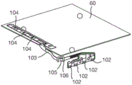
The control circuitry implemented in the IC chip 30 is also electrically connected to the AF actuator means 24 by a Flexible Printed Circuit (FPC) tape 103, the FPC tape 103 being physically connected between the support structure 4 and the lens assembly 20, as shown in fig. 3 and 4, and arranged as follows.
The support structure 4 has input conductive tabs 102 arranged along the base 5 on a first side of the camera assembly 1 extending transverse to the X-direction. Control signals from a control circuit implemented in the IC chip 30 and power from an external power source are supplied to the input conductive tab 102. Similarly, the movable platform 60 fixed to the lens assembly 20 has output conductive tabs 104, the output conductive tabs 104 being arranged on a second side of the camera assembly 1 adjacent to the first side, extending transversely to the direction Y.
The FPC tape 103 is physically and electrically connected between the input conductive tabs 102 and the output conductive tabs 104. In this example, the FPC tape provides four separate electrical connections between the input conductive tabs 102 and the output conductive tabs 104, but in general any number of connections may be provided. The output conductive tabs 104 are connected to the AF actuator device 24 for providing control signals and power to the AF actuator device 24. Alternatively, the sensor signal may be provided from the AF actuator assembly 24 to the control circuit implemented in the IC chip 30 in the opposite direction through the electrical connection on the FPC tape 103.
The FPC tape 103 may be of conventional construction, for example comprising a flexible substrate made of a suitable material, for example a plastic such as polyimide, PEEK or polyester.
The FPC tape 103 extends from the input conductive tabs 102 along a first side and then bends around the corner 105 before extending along a second side to the output conductive tabs 104.
Since the flexible printed circuit strip is arranged to bend around the corner 105, it accommodates movement of the lens assembly 20 relative to the support structure 4 in any direction in a plane perpendicular to the optical axis O. The FPC tape typically flexes in a single direction perpendicular to its surface while resisting movement in other directions transverse to its surface or along its length. However, when the FPC tape 103 is bent, the two portions of the FPC tape 103 on each side of the corner 105 can accommodate movement in different directions with minimal strain. That is, a portion of the FPC tape 103 on the first side may accommodate movement of the lens assembly 20 in the X direction, and a portion of the FPC tape 103 on the second side may accommodate movement of the lens assembly 20 in the Y direction.
In this example, the corner 105 is 90 degrees and extends along an axis parallel to the optical axis O. This is advantageous as it provides the best accommodation of the movement of the lens assembly 20 relative to the support structure 4 in a plane perpendicular to the optical axis O, however other configurations with a bend around a corner may provide similar effects.
Optionally, the FPC tape 103 may be connected to a bend former 106 as shown in fig. 4 to 6, however for clarity the bend former 106 is not shown in fig. 3. A bend former 106 is connected to the FPC tape 103 on each side of the corner 105.
More specifically, the bend former 106 is shaped to include two mounting portions 108 and a bridge portion 109. The mounting portions 108 are connected to the FPC tape 103 at spaced locations on each side of the corner 105, as best shown in fig. 6. The bridge portion 109 extends between the mounting portions 108 outside the FPC tape 103, and is therefore not connected to the FPC tape 103.
In an alternative form shown in fig. 7, the bend former 106 may comprise two bridge portions 109 extending between the mounting portions 108 outside the FPC tape 103 on opposite sides of the FPC tape 103.
The bend former 106 restricts bending of the FPC tape 103 and accurately positions the corner 105. In particular, the corner 105 may be formed without plastically deforming the FPC tape 103. This reduces the strain on the FPC tape 103 that might otherwise be caused by the corner 105. Similarly, the bend former 106 keeps the two portions of the FPC tape 103 on each side of the corner 105 flat and prevents the tape from bending, contacting the walls of the container 7 and interfering with movement.
The bend former 106 may advantageously be formed of metal, but generally any material that provides suitable structural characteristics may be used, such as plastic.
The bend former 106 may be formed from a sheet, for example a metal sheet. In this case, the bend former 106 may initially be planar and then shaped by plastically deforming the bridge portion 109 along the axis 107, the bridge portion 109 being parallel to the corner 105 after connection to the FPC tape 103.
In fig. 3 and 4, the output conductive tabs 104 are shown as being horizontally located on the movable platform 60. Typically, the output conductive tabs 104 will be formed onto an upper portion of the OIS assembly 40 for connection to the AF actuator assembly 24. As an alternative shown in fig. 8, the FPC tape 103 may be provided with connector tabs 109 for connection to custom tabs 110 provided on the outer surface of the lens holder 21 of the lens assembly 20 and thus placed vertically. In this case, the lens assembly 20 may support the connector tabs 109 of the FPC 103. At manufacture, the lens assembly 20 supporting the custom tabs 110 is attached to the OIS assembly 40 supporting the FPC tape 103, and then the connector tabs 109 of the FPC103 are connected to the custom tabs 110 on the lens assembly 20.
The reason why the crimp plate 62 is formed with the step 64 to position the crimp portion 61 above the plane P of the crimp plate 62 in a direction toward the lens assembly 20 will now be discussed, as shown in fig. 9. This has the result of moving the lens assembly 20 relative to the OIS assembly 40 so that a portion of the OIS assembly 40 overlaps the lens assembly 20 in a direction along the optical axis O, the overlapping portion of the OIS assembly including the SMA actuator wires 80. The overlap is with the lens holder 23 and also with the lens holder 21. This overlapping arrangement is in contrast to the camera disclosed in WO-2014/083318, in which the lens assembly is simply stacked on the OIS assembly.
Here, reference to the direction of overlap along the optical axis O has the normal meaning as the direction along which overlap (which is overlap when viewed perpendicular to the optical axis O) occurs. Therefore, the height of the camera apparatus 1 in the direction along the optical axis O can be reduced. This reduction in height is very important because of the ever-increasing demand for miniaturization. In many electronic devices, such as smart phones, height is particularly important, where there is a demand to reduce the thickness of the device. The reduction in height is achieved at the expense of an increased footprint (footprint) perpendicular to the optical axis O, but it is generally more important to reduce the height.
Some further alternative structures for the camera assembly 1 will now be described with reference to fig. 10 to 12, which achieve similar height reduction by similar overlap, and fig. 10 to 12 show alternative structures for the camera assembly 1. In addition to the improvements described below, in each of the alternative constructions, the camera assembly 1 has the same arrangement as discussed above, and common reference numerals will be used for common components. In particular, fig. 10-12 show an OIS assembly 40, the OIS assembly 40 including a support plate 50, a movable platform 60, SMA actuator wires 80 and balls 75. The support plate 50 and the movable platform 60 are shown to comprise a plurality of laminate layers including a crimping plate 62, the crimping plate 62 comprising a crimping portion 61 that crimps an SMA actuator wire 80. In the structure of fig. 10 to 12, the crimp plate 62 is formed without the step 64 so that the crimping portion 61 is located in the plane of the rest of the crimp plate 62.
Fig. 10 shows the configuration of a camera assembly 1 as a comparative example, in which a lens assembly 20 is stacked on an OIS assembly 40 in a similar manner to WO-2014/083318. Accordingly, the OIS assembly 40 does not overlap the lens assembly 20. Fig. 10 shows that the support plate 50 and the movable platform 60 are ring-shaped, surrounding an aperture 111, through which aperture 111 light from the lens assembly 20 is transmitted to an image sensor (not shown in fig. 10). The crimp plate 62 and SMA actuator wires 80 are taller (in a direction along the optical axis O towards the lens assembly 20) than the balls 75 on the stack of the support plate 50 and the movable platform 60.
Fig. 11 shows a configuration of the camera assembly 1 in which a portion of the OIS assembly 40 overlaps the lens assembly 20 in a direction along the optical axis O. In this case, the overlapping portion of the OIS assembly 40 includes the SMA actuator wires 80 and the movable platform 60, but does not include the balls 75 and the support plate 50. To accommodate this overlap, the movable platform 60 includes a bracket 114 as its uppermost layer, the bracket 114 has a step 115 offset from the rest of the bracket 114 in a direction along the optical axis O away from the lens assembly 20, and the lens assembly 20 is mounted on the step 115. Fig. 11 shows the partial overlap of the OIS assembly 40 and the lens assembly 20 along the optical axis O. This provides a slight reduction in height and some increase in footprint to accommodate movable platform 60 on the outside of lens assembly 20.
Fig. 12 shows a configuration of the camera assembly 1 in which the entirety of the OIS assembly 40 (including the ball 75 and the support plate 50) overlaps the lens assembly 20 in a direction along the optical axis O. In this case, the OIS assembly 40 is almost entirely outside the lens assembly 20. Fig. 11 shows the total overlap of the OIS assembly 40 and the lens assembly 20 along the optical axis O. To accommodate this overlap, the movable platform 60 includes a bracket 114 in a configuration similar to that of fig. 11, except that the step 115 provides a large offset from the rest of the bracket 114. This configuration provides a very significant height savings because the ball 75 can typically measure about 0.6mm, in which case a height reduction of about 1mm can be achieved.
Claims (10)
1. A camera assembly, comprising:
a support structure;
a lens assembly comprising a lens holder, at least one lens having an optical axis and being supported on the lens holder in a manner allowing movement of the at least one lens along its optical axis, and an autofocus actuator arrangement arranged to move the lens along the optical axis relative to the lens holder, wherein the lens holder is supported on the support structure in a manner allowing movement of the lens assembly relative to the support structure in a plane perpendicular to the optical axis;
an optical image stabilization assembly arranged to move the lens holder relative to the support structure in the plane perpendicular to the optical axis,
a flexible printed circuit tape bent predominantly in a direction perpendicular to a surface thereof, the flexible printed circuit tape being connected between the support structure and the lens assembly and providing electrical connection to the autofocus actuator arrangement, the flexible printed circuit tape being bent around a corner extending along an axis parallel to the optical axis such that there is a portion of the flexible printed circuit tape on each side of the corner, the portion of the flexible printed circuit tape on each side of the corner accommodating movement of the lens assembly in different directions perpendicular to the optical axis; and
a bend former connected to the flexible printed circuit tape on each side of the corner.
2. The camera assembly of claim 1, wherein the flexible printed circuit tape is bent around a 90 degree corner.
3. The camera assembly of claim 1, wherein the bend shaper is made of metal.
4. A camera assembly according to claim 3, wherein the bend former comprises two mounting portions connected to the flexible printed circuit tape at spaced apart locations on each side of the corner, and at least one bridge portion extending between the mounting portions without being connected to the flexible printed circuit tape.
5. A camera assembly according to claim 4, wherein the at least one bridge portion extends between the mounting portions outside the flexible printed circuit tape.
6. A camera assembly according to claim 5, wherein the at least one bridge portion comprises two bridge portions extending between the mounting portions outside the flexible printed circuit tape on opposite sides of the flexible printed circuit tape.
7. A camera assembly according to any one of claims 4 to 6, wherein the bend former is formed from a sheet in which the bridge portion has been plastically deformed.
8. The camera assembly of claim 1, wherein the optical image stabilization assembly comprises a shape memory alloy wire.
9. The camera assembly of claim 1, further comprising an image sensor mounted to the support structure.
10. The camera assembly of claim 1, wherein the at least one lens has a diameter of 10mm or less.
Priority Applications (1)
| Application Number | Priority Date | Filing Date | Title |
|---|---|---|---|
| CN201911354285.8A CN111308830A (en) | 2014-07-18 | 2015-07-15 | Camera assembly |
Applications Claiming Priority (3)
| Application Number | Priority Date | Filing Date | Title |
|---|---|---|---|
| GB1412848.2 | 2014-07-18 | ||
| GBGB1412848.2A GB201412848D0 (en) | 2014-07-18 | 2014-07-18 | Suspension system for a camera lens element |
| PCT/GB2015/052043 WO2016009200A1 (en) | 2014-07-18 | 2015-07-15 | Camera assembly |
Related Child Applications (1)
| Application Number | Title | Priority Date | Filing Date |
|---|---|---|---|
| CN201911354285.8A Division CN111308830A (en) | 2014-07-18 | 2015-07-15 | Camera assembly |
Publications (2)
| Publication Number | Publication Date |
|---|---|
| CN107077044A CN107077044A (en) | 2017-08-18 |
| CN107077044B true CN107077044B (en) | 2020-01-07 |
Family
ID=51494846
Family Applications (2)
| Application Number | Title | Priority Date | Filing Date |
|---|---|---|---|
| CN201580044156.2A Active CN107077044B (en) | 2014-07-18 | 2015-07-15 | Camera assembly |
| CN201911354285.8A Pending CN111308830A (en) | 2014-07-18 | 2015-07-15 | Camera assembly |
Family Applications After (1)
| Application Number | Title | Priority Date | Filing Date |
|---|---|---|---|
| CN201911354285.8A Pending CN111308830A (en) | 2014-07-18 | 2015-07-15 | Camera assembly |
Country Status (7)
| Country | Link |
|---|---|
| US (3) | US10175499B2 (en) |
| EP (1) | EP3170048A1 (en) |
| JP (1) | JP2017522615A (en) |
| KR (1) | KR20170062441A (en) |
| CN (2) | CN107077044B (en) |
| GB (1) | GB201412848D0 (en) |
| WO (1) | WO2016009200A1 (en) |
Families Citing this family (44)
| Publication number | Priority date | Publication date | Assignee | Title |
|---|---|---|---|---|
| GB201412848D0 (en) * | 2014-07-18 | 2014-09-03 | Cambridge Mechatronics Ltd | Suspension system for a camera lens element |
| US9366879B1 (en) | 2014-12-02 | 2016-06-14 | Hutchinson Technology Incorporated | Camera lens suspension with polymer bearings |
| US9454016B1 (en) | 2015-03-06 | 2016-09-27 | Hutchinson Technology Incorporated | Camera lens suspension with integrated electrical leads |
| WO2016161075A1 (en) | 2015-04-02 | 2016-10-06 | Hutchinson Technology Incorporated | Wire feeding and attaching system for camera lens suspensions |
| CN107277304B (en) * | 2016-04-01 | 2020-11-20 | 台湾东电化股份有限公司 | Camera module and control method thereof |
| US10670878B2 (en) | 2016-05-19 | 2020-06-02 | Hutchinson Technology Incorporated | Camera lens suspensions |
| US11536930B2 (en) | 2016-05-24 | 2022-12-27 | Microsoft Licensing Technology, LLC. | Suspended actuator |
| EP3468789A4 (en) | 2016-06-09 | 2020-02-26 | Hutchinson Technology Incorporated | Shape memory alloy wire attachment structures with adhesive for a suspension assembly |
| US10542201B2 (en) | 2016-06-29 | 2020-01-21 | Microsoft Technology Licensing, Llc | Split-camera autoalignment |
| US10488186B2 (en) | 2016-06-29 | 2019-11-26 | Microsoft Technology Licensing, Llc | Alignment detection for split camera |
| CN111522183B (en) * | 2016-07-29 | 2021-12-31 | 台湾东电化股份有限公司 | Lens driving device |
| CN107664895B (en) * | 2016-07-29 | 2020-06-09 | 台湾东电化股份有限公司 | Lens driving device |
| CN109416498B (en) * | 2016-08-08 | 2022-03-22 | 剑桥机电有限公司 | Dual camera apparatus |
| US20180063438A1 (en) * | 2016-08-24 | 2018-03-01 | Hutchinson Technology Incorporated | Dual Camera Assemblies With Optical Image Stabilization |
| GB201707542D0 (en) * | 2017-05-11 | 2017-06-28 | Cambridge Mechatronics Ltd | Compact SMA shutter actuator |
| WO2018211047A1 (en) * | 2017-05-17 | 2018-11-22 | Cambridge Mechatronics Limited | Electrical connections for sma actuators |
| US10863094B2 (en) * | 2017-07-17 | 2020-12-08 | Apple Inc. | Camera with image sensor shifting |
| JP2019029979A (en) * | 2017-08-04 | 2019-02-21 | ソニーセミコンダクタソリューションズ株式会社 | Semiconductor device, electronic apparatus, and manufacturing method |
| CN109782412B (en) * | 2017-11-15 | 2024-04-05 | 新思考电机有限公司 | Lens driving device, camera device and electronic equipment |
| US10809524B2 (en) | 2018-01-08 | 2020-10-20 | Facebook Technologies, Llc | Varifocal apparatuses, systems, and methods employing a deformable stepped lens |
| CN108174104A (en) * | 2018-01-31 | 2018-06-15 | 上海信迈电子科技有限公司 | Anti-shaking structure, stabilization system and with its photographic device |
| GB201820383D0 (en) * | 2018-12-14 | 2019-01-30 | Cambridge Mechatronics Ltd | Zero power hold SMA Actuator assembly |
| JP6739573B1 (en) * | 2019-03-29 | 2020-08-12 | エーエーシー コミュニケーション テクノロジーズ(ジョウシュウ)カンパニーリミテッド | Lens drive for camera |
| GB201904840D0 (en) * | 2019-04-05 | 2019-05-22 | Cambridge Mechatronics Ltd | A crimp and method for loading a wire therein |
| CN110750023A (en) * | 2019-09-11 | 2020-02-04 | 瑞声科技(新加坡)有限公司 | Lens module and electronic equipment |
| CN110727122A (en) * | 2019-09-11 | 2020-01-24 | 瑞声科技(新加坡)有限公司 | Optical anti-shake component |
| CN112752013A (en) | 2019-10-30 | 2021-05-04 | 晋城三赢精密电子有限公司 | Anti-shake device, camera module and electronic device |
| CN115755426A (en) * | 2019-11-25 | 2023-03-07 | 新思考电机有限公司 | Optical member driving device, camera device, and electronic apparatus |
| GB2589385B (en) | 2019-12-01 | 2022-01-12 | Cambridge Mechatronics Ltd | Actuator assembly |
| CN112914532A (en) * | 2019-12-06 | 2021-06-08 | 研能科技股份有限公司 | Blood pressure measuring module |
| CN111158102B (en) * | 2019-12-30 | 2021-07-02 | 诚瑞光学(常州)股份有限公司 | Actuation device and method of controlling SMA actuator wires |
| US11388322B2 (en) | 2020-02-07 | 2022-07-12 | Samsung Electro-Mechanics Co., Ltd. | Camera module having rotatable lens module and frames and portable electronic device including the same |
| GB2592579A (en) | 2020-02-26 | 2021-09-08 | Cambridge Mechatronics Ltd | A camera assembly |
| CN111443498A (en) * | 2020-04-15 | 2020-07-24 | Oppo广东移动通信有限公司 | Lens module and electronic equipment |
| GB2594921A (en) * | 2020-04-16 | 2021-11-17 | Cambridge Mechatronics Ltd | Actuator assembly |
| CN113572918B (en) * | 2020-04-29 | 2022-10-14 | 宁波舜宇光电信息有限公司 | Periscopic continuous light-variable module and corresponding multi-camera module |
| CN112600992B (en) | 2020-05-13 | 2022-05-17 | 广州立景创新科技有限公司 | Image acquisition module and assembling method thereof |
| CN111641761B (en) * | 2020-05-27 | 2022-04-29 | 维沃移动通信有限公司 | Camera module and electronic equipment |
| CN212211175U (en) * | 2020-06-23 | 2020-12-22 | 新思考电机有限公司 | OIS motor drive structure, OIS motor, camera device |
| CN114079712B (en) * | 2020-08-11 | 2022-09-27 | 宁波舜宇光电信息有限公司 | Anti-shake camera module and preparation method thereof |
| US11483461B2 (en) * | 2020-08-12 | 2022-10-25 | Apple Inc. | Techniques for forming suspension assemblies for a camera |
| GB2602627B (en) * | 2020-12-31 | 2023-06-07 | Cambridge Mechatronics Ltd | Actuator assemblies |
| CN112987327B (en) * | 2021-03-03 | 2021-10-29 | 上海比路电子股份有限公司 | Anti-shake device for camera lens |
| GB202119163D0 (en) * | 2021-12-31 | 2022-02-16 | Cambridge Mechatronics Ltd | Actuator assembly |
Citations (7)
| Publication number | Priority date | Publication date | Assignee | Title |
|---|---|---|---|---|
| CN1599428A (en) * | 2003-08-13 | 2005-03-23 | 西铁城电子股份有限公司 | Compact imaging module |
| CN1776520A (en) * | 2004-11-17 | 2006-05-24 | 奥林巴斯株式会社 | Lens barrel and electronic device |
| CN101573648A (en) * | 2006-12-28 | 2009-11-04 | 株式会社腾龙 | Lens driving device |
| CN102483557A (en) * | 2010-07-07 | 2012-05-30 | 松下电器产业株式会社 | Camera drive device |
| WO2013175197A1 (en) * | 2012-05-25 | 2013-11-28 | Cambridge Mechatronics Limited | Shape memory alloy actuation apparatus |
| WO2014083318A1 (en) * | 2012-11-27 | 2014-06-05 | Cambridge Mechatronics Limited | Suspension system for a camera lens element |
| CN103913931A (en) * | 2012-12-28 | 2014-07-09 | 三星电子株式会社 | Flexible printed circuit board and small camera apparatus including the same |
Family Cites Families (20)
| Publication number | Priority date | Publication date | Assignee | Title |
|---|---|---|---|---|
| US2168911A (en) * | 1937-05-07 | 1939-08-08 | Pierre H Meyer | Corner bracket for shelves |
| US6143047A (en) * | 1998-02-06 | 2000-11-07 | Facilitec Corporation | Effluent containment assembly |
| WO2007038652A2 (en) * | 2005-09-28 | 2007-04-05 | Illumination Management Solutions, Inc. | An led-fiber optic combination for simulating neon lit signage |
| JP5250544B2 (en) | 2006-03-30 | 2013-07-31 | ケンブリッジ メカトロニクス リミテッド | Camera lens drive device |
| ATE503928T1 (en) | 2007-02-12 | 2011-04-15 | Cambridge Mechatronics Ltd | TRIGGER DEVICE FOR SHAPE MEMORY ALLOY |
| ATE508277T1 (en) | 2007-10-30 | 2011-05-15 | Cambridge Mechatronics Ltd | MEMORY ALLOY ACTUATOR |
| KR100982266B1 (en) * | 2008-04-24 | 2010-09-14 | 삼성전기주식회사 | Lens actuating module |
| GB2474173B (en) * | 2008-07-30 | 2011-11-09 | Cambridge Mechatronics Ltd | Shape memory alloy actuation apparatus |
| US8441749B2 (en) * | 2009-02-09 | 2013-05-14 | Cambridge Mechatronics Limited | Shape memory alloy actuation apparatus |
| US8059950B2 (en) * | 2009-07-28 | 2011-11-15 | Tamron Co., Ltd. | Image stabilizing apparatus, lens apparatus, imaging apparatus, and correction optical apparatus |
| JP5735991B2 (en) * | 2010-02-26 | 2015-06-17 | ケンブリッジ メカトロニクス リミテッド | SMA actuator |
| WO2011146921A1 (en) * | 2010-05-21 | 2011-11-24 | Mladen Lijesnic | Connector for panel members |
| US8866918B2 (en) * | 2010-09-22 | 2014-10-21 | Cambridge Mechatronics Limited | Optical image stabilisation |
| TWI416240B (en) * | 2011-03-30 | 2013-11-21 | Largan Precision Co Ltd | Photographing module |
| KR101354775B1 (en) * | 2011-12-23 | 2014-01-22 | 삼성전기주식회사 | Camera module |
| US9372352B2 (en) * | 2013-08-23 | 2016-06-21 | Samsung Electro-Mechanics Co., Ltd. | Lens driving device and camera module including the same |
| WO2015104908A1 (en) * | 2014-01-10 | 2015-07-16 | シャープ株式会社 | Camera module |
| GB201412848D0 (en) * | 2014-07-18 | 2014-09-03 | Cambridge Mechatronics Ltd | Suspension system for a camera lens element |
| US9366879B1 (en) | 2014-12-02 | 2016-06-14 | Hutchinson Technology Incorporated | Camera lens suspension with polymer bearings |
| US9454016B1 (en) | 2015-03-06 | 2016-09-27 | Hutchinson Technology Incorporated | Camera lens suspension with integrated electrical leads |
-
2014
- 2014-07-18 GB GBGB1412848.2A patent/GB201412848D0/en not_active Ceased
-
2015
- 2015-07-15 KR KR1020177004461A patent/KR20170062441A/en unknown
- 2015-07-15 WO PCT/GB2015/052043 patent/WO2016009200A1/en active Application Filing
- 2015-07-15 EP EP15741588.6A patent/EP3170048A1/en not_active Withdrawn
- 2015-07-15 JP JP2017522741A patent/JP2017522615A/en not_active Withdrawn
- 2015-07-15 CN CN201580044156.2A patent/CN107077044B/en active Active
- 2015-07-15 US US15/326,865 patent/US10175499B2/en active Active
- 2015-07-15 CN CN201911354285.8A patent/CN111308830A/en active Pending
-
2018
- 2018-11-20 US US16/196,959 patent/US11526021B2/en active Active
-
2022
- 2022-11-10 US US17/984,847 patent/US20230071152A1/en active Pending
Patent Citations (7)
| Publication number | Priority date | Publication date | Assignee | Title |
|---|---|---|---|---|
| CN1599428A (en) * | 2003-08-13 | 2005-03-23 | 西铁城电子股份有限公司 | Compact imaging module |
| CN1776520A (en) * | 2004-11-17 | 2006-05-24 | 奥林巴斯株式会社 | Lens barrel and electronic device |
| CN101573648A (en) * | 2006-12-28 | 2009-11-04 | 株式会社腾龙 | Lens driving device |
| CN102483557A (en) * | 2010-07-07 | 2012-05-30 | 松下电器产业株式会社 | Camera drive device |
| WO2013175197A1 (en) * | 2012-05-25 | 2013-11-28 | Cambridge Mechatronics Limited | Shape memory alloy actuation apparatus |
| WO2014083318A1 (en) * | 2012-11-27 | 2014-06-05 | Cambridge Mechatronics Limited | Suspension system for a camera lens element |
| CN103913931A (en) * | 2012-12-28 | 2014-07-09 | 三星电子株式会社 | Flexible printed circuit board and small camera apparatus including the same |
Also Published As
| Publication number | Publication date |
|---|---|
| US20230071152A1 (en) | 2023-03-09 |
| JP2017522615A (en) | 2017-08-10 |
| WO2016009200A1 (en) | 2016-01-21 |
| US20190086686A1 (en) | 2019-03-21 |
| US11526021B2 (en) | 2022-12-13 |
| GB201412848D0 (en) | 2014-09-03 |
| US20170219842A1 (en) | 2017-08-03 |
| EP3170048A1 (en) | 2017-05-24 |
| KR20170062441A (en) | 2017-06-07 |
| CN107077044A (en) | 2017-08-18 |
| CN111308830A (en) | 2020-06-19 |
| US10175499B2 (en) | 2019-01-08 |
Similar Documents
| Publication | Publication Date | Title |
|---|---|---|
| CN107077044B (en) | Camera assembly | |
| US11199183B2 (en) | Shape memory alloy actuators and methods thereof | |
| JP6391584B2 (en) | Suspension system for camera lens elements | |
| US10397478B2 (en) | Bearing limiter structures in optical image stabilization suspensions | |
| US11105319B2 (en) | Shape memory alloy actuators and methods thereof | |
| CN112654786B (en) | Shape memory alloy actuator and method thereof | |
| US11668288B2 (en) | Shape memory alloy actuators and methods thereof | |
| US11448853B2 (en) | Shape memory alloy actuators and methods thereof | |
| CN218816802U (en) | Actuator and actuator module assembly | |
| WO2023126633A1 (en) | Actuator assembly | |
| CN116615912A (en) | Actuator assembly | |
| JP2023530250A (en) | Shape memory alloy actuator and method | |
| CN117597938A (en) | Actuator assembly | |
| CN115701714A (en) | Actuator assembly |
Legal Events
| Date | Code | Title | Description |
|---|---|---|---|
| PB01 | Publication | ||
| PB01 | Publication | ||
| SE01 | Entry into force of request for substantive examination | ||
| SE01 | Entry into force of request for substantive examination | ||
| GR01 | Patent grant | ||
| GR01 | Patent grant |