CN106938535B - A fully automatic sliding light counting machine and its application method - Google Patents
A fully automatic sliding light counting machine and its application method Download PDFInfo
- Publication number
- CN106938535B CN106938535B CN201710322174.3A CN201710322174A CN106938535B CN 106938535 B CN106938535 B CN 106938535B CN 201710322174 A CN201710322174 A CN 201710322174A CN 106938535 B CN106938535 B CN 106938535B
- Authority
- CN
- China
- Prior art keywords
- platform
- cylinder
- feeding
- chute
- end surface
- Prior art date
- Legal status (The legal status is an assumption and is not a legal conclusion. Google has not performed a legal analysis and makes no representation as to the accuracy of the status listed.)
- Active
Links
- 238000000034 method Methods 0.000 title claims abstract description 16
- 239000000463 material Substances 0.000 claims description 39
- 238000001125 extrusion Methods 0.000 claims description 31
- 230000006698 induction Effects 0.000 claims description 8
- 230000008569 process Effects 0.000 claims description 7
- 230000003746 surface roughness Effects 0.000 abstract description 6
- 238000012545 processing Methods 0.000 abstract description 4
- 229920001343 polytetrafluoroethylene Polymers 0.000 abstract description 3
- 239000004810 polytetrafluoroethylene Substances 0.000 abstract description 3
- 238000007789 sealing Methods 0.000 abstract description 3
- -1 polytetrafluoroethylene Polymers 0.000 abstract description 2
- 239000000047 product Substances 0.000 description 90
- 238000013461 design Methods 0.000 description 27
- 238000010586 diagram Methods 0.000 description 10
- 230000009471 action Effects 0.000 description 9
- 238000009434 installation Methods 0.000 description 9
- 238000009499 grossing Methods 0.000 description 6
- 230000000903 blocking effect Effects 0.000 description 4
- 230000005484 gravity Effects 0.000 description 4
- 238000003825 pressing Methods 0.000 description 3
- 238000004512 die casting Methods 0.000 description 2
- 238000012986 modification Methods 0.000 description 2
- 230000004048 modification Effects 0.000 description 2
- 230000008859 change Effects 0.000 description 1
- 238000004891 communication Methods 0.000 description 1
- 238000005516 engineering process Methods 0.000 description 1
- 239000012467 final product Substances 0.000 description 1
- 238000004519 manufacturing process Methods 0.000 description 1
- 230000000717 retained effect Effects 0.000 description 1
- 238000005096 rolling process Methods 0.000 description 1
- 239000004576 sand Substances 0.000 description 1
Images


Classifications
-
- B—PERFORMING OPERATIONS; TRANSPORTING
- B29—WORKING OF PLASTICS; WORKING OF SUBSTANCES IN A PLASTIC STATE IN GENERAL
- B29C—SHAPING OR JOINING OF PLASTICS; SHAPING OF MATERIAL IN A PLASTIC STATE, NOT OTHERWISE PROVIDED FOR; AFTER-TREATMENT OF THE SHAPED PRODUCTS, e.g. REPAIRING
- B29C59/00—Surface shaping of articles, e.g. embossing; Apparatus therefor
- B29C59/02—Surface shaping of articles, e.g. embossing; Apparatus therefor by mechanical means, e.g. pressing
-
- G—PHYSICS
- G06—COMPUTING; CALCULATING OR COUNTING
- G06M—COUNTING MECHANISMS; COUNTING OF OBJECTS NOT OTHERWISE PROVIDED FOR
- G06M1/00—Design features of general application
-
- B—PERFORMING OPERATIONS; TRANSPORTING
- B29—WORKING OF PLASTICS; WORKING OF SUBSTANCES IN A PLASTIC STATE IN GENERAL
- B29C—SHAPING OR JOINING OF PLASTICS; SHAPING OF MATERIAL IN A PLASTIC STATE, NOT OTHERWISE PROVIDED FOR; AFTER-TREATMENT OF THE SHAPED PRODUCTS, e.g. REPAIRING
- B29C59/00—Surface shaping of articles, e.g. embossing; Apparatus therefor
- B29C59/02—Surface shaping of articles, e.g. embossing; Apparatus therefor by mechanical means, e.g. pressing
- B29C2059/027—Grinding; Polishing
Landscapes
- Engineering & Computer Science (AREA)
- Physics & Mathematics (AREA)
- General Physics & Mathematics (AREA)
- Theoretical Computer Science (AREA)
- Mechanical Engineering (AREA)
- Feeding Of Articles To Conveyors (AREA)
Abstract
Description
技术领域technical field
本发明属于自动化机械设备技术领域,具体涉及一种全自动溜光计数机及其使用方法。The invention belongs to the technical field of automatic machinery and equipment, and in particular relates to a fully automatic sliding light counting machine and a using method thereof.
背景技术Background technique
在填充改性聚四氟乙烯密封圈加工中,由于受到材质特性的影响,该产品最佳生产工艺是用CNC数控车床车加工出来的。但常规加工工艺所加工出来的产品,其内外圆的表面粗糙度与客户的期望存在一定差距。经尝试,用滚沙工艺处理的产品,其表面粗糙度能达到客户要求,但同时必然地造成了尖锐角的磨损,在尖锐角位置出现了被倒钝的圆弧,也不能达到客户的要求。In the processing of filled modified PTFE sealing ring, due to the influence of material characteristics, the best production process of this product is processed by CNC lathe. However, there is a certain gap between the surface roughness of the inner and outer circles of the products processed by conventional processing technology and the expectations of customers. After trying, the surface roughness of the products processed by the sand rolling process can meet the customer's requirements, but at the same time, it will inevitably cause sharp-edged wear, and blunt arcs appear at the sharp-edged positions, which cannot meet the customer's requirements. .
发明内容Contents of the invention
本发明的目的是:旨在提供一种全自动溜光计数机及其使用方法,用来解决填充改性聚四氟乙烯密封圈在常规加工中导致的表面粗糙度和尖锐角之间的矛盾问题。The purpose of the present invention is to provide a full-automatic slip counting machine and its use method, which is used to solve the contradiction between surface roughness and sharp angles caused by filling modified polytetrafluoroethylene sealing rings in conventional processing .
为实现上述技术目的,本发明采用的技术方案如下:For realizing above-mentioned technical purpose, the technical scheme that the present invention adopts is as follows:
一种全自动溜光计数机,包括机柜和PLC处理器,所述机柜上端面右侧设有振动盘,所述振动盘出料端连接有料道,所述料道下方设有直振动筛,所述料道左侧设有工作平台,所述工作平台上端面设有第一滑槽台,所述第一滑槽台上端面设有从前至后的第一滑槽,所述第一滑槽内设有送料台,所述第一滑槽台后端面设有送料缸,所述送料缸前端设有送料杆,所述送料杆连接送料台,所述工作平台上端面还设有红外线感应器,所述工作平台前端面设有外环台,所述外环台上端面中央设有外环孔,所述外环台上端面设有定位台,所述定位台上端面设有通孔,所述定位台上端面设有第二滑槽台,所述第二滑槽台后端面设有从上至下的第二滑槽,所述第二滑槽内设有挤压块,所述第二滑槽台上端面设有挤压缸,所述挤压缸下端设有挤压杆,所述挤压杆连接挤压块,所述挤压块下端面设有压筒,所述压筒外轮廓与通孔相匹配,所述压筒下端面设有压孔,所述外环孔内设有芯轴,所述芯轴上部设有圆台,所述圆台顶端设有圆锥台,所述圆台位于外环孔内,所述芯轴下方设有挡料板,所述机柜上端面于挡料板对应位置设有第三滑槽台,所述第三滑槽台上端面设有从左至右的第三滑槽,所述第三滑槽台左端面设有落料缸,所述落料缸右端面设有落料杆,所述落料杆连接挡料板,所述机柜于挡料板下方设有抽屉,所述红外线感应器输出端连接PLC处理器输入端,所述PLC 处理器输出端分别连接送料缸、挤压缸和落料缸。A fully automatic sliding light counting machine, including a cabinet and a PLC processor, a vibrating plate is provided on the right side of the upper end of the cabinet, a material channel is connected to the discharge end of the vibrating plate, and a straight vibrating screen is provided under the material channel. A working platform is provided on the left side of the material channel, and a first chute table is provided on the upper end of the working platform, and a first chute from front to back is provided on the upper end of the first chute table, and the first chute A feeding table is provided inside, a feeding cylinder is provided on the rear end of the first chute table, a feeding rod is provided at the front end of the feeding cylinder, and the feeding rod is connected to the feeding table, and an infrared sensor is also provided on the upper end of the working platform , the front end of the working platform is provided with an outer ring platform, the center of the upper end surface of the outer ring platform is provided with an outer ring hole, the upper end surface of the outer ring platform is provided with a positioning platform, and the upper end surface of the positioning platform is provided with a through hole, The upper end surface of the positioning platform is provided with a second chute platform, the rear end surface of the second chute platform is provided with a second chute from top to bottom, and an extrusion block is arranged in the second chute, and the The upper end of the second chute platform is provided with an extrusion cylinder, and the lower end of the extrusion cylinder is provided with an extrusion rod, and the extrusion rod is connected to an extrusion block, and the lower end of the extrusion block is provided with a pressure cylinder. The outer contour of the cylinder matches the through hole, the lower end of the pressure cylinder is provided with a pressure hole, the outer ring hole is provided with a mandrel, the upper part of the mandrel is provided with a circular platform, and the top of the circular platform is provided with a conical platform. The round platform is located in the outer ring hole, a material retaining plate is provided under the mandrel, a third chute platform is provided on the upper end surface of the cabinet at the corresponding position of the material retaining plate, and a third chute platform is provided on the upper end surface of the third chute platform. The third chute from left to right, the left end of the third chute platform is provided with a blanking cylinder, the right end of the blanking cylinder is provided with a blanking rod, and the blanking rod is connected to the blocking plate, and the cabinet A drawer is arranged under the baffle plate, the output end of the infrared sensor is connected to the input end of the PLC processor, and the output end of the PLC processor is respectively connected to the feeding cylinder, extrusion cylinder and blanking cylinder.
采用上述技术方案的发明,把产品倒入振动盘,产品在振动盘的作用下从出料端进入料道,产品在直振动筛的作用下进入工作平台被红外线感应器感应、并且把感应信号传入PLC 处理器,PLC处理器计数并且控制送料缸运动,向前推动产品至通孔上方,并套入圆锥台然后 PLC处理器控制送料缸复位,同时,PLC处理器控制挤压缸运动,使压筒下压,把产品压入外环孔并且套设在圆台上,此时,圆台通过产品与外环孔紧密配合,实现溜光处理,处理后的产品套在圆台处,PLC处理器控制送料缸继续推送产品,然后使用压筒下压,使圆台外壁滞留多个产品,当产品在圆台外壁积累到一定数量时,产品脱离圆台和外环孔在自身重力的作用下落到挡料板上,此时,由于产品还套设在芯轴上,产品在芯轴上积累,PLC处理器的计数达到一定数量时,控制落料缸动作,使挡料板向左运动,此时芯轴上积累的产品在重力的作用下,掉入抽屉,此时,由于芯轴通过滞留在圆台处的一些产品和外环孔实现紧配合,故芯轴不会掉落。这样的结构设计,产品外表面在通过外环孔时受到挤压,对产品外表面进行了溜光,产品内表面在通过圆台时受到挤压,对产品内表面进行了溜光,当多个产品滞留在圆台与外环孔之间时,压筒对产品的上下端面均进行了压铸处理,大大降低了产品表面的粗糙度,而且避免了产品尖锐角被磨损的问题;同时由于使用全自动化设计,工人在调试好机器后,只需要把待处理的产品倒入振动盘,然后隔一段时间从抽屉里取走溜光完成的产品即可,大大减少了工人的劳动强度,而且具有计数功能,用此机器加工后的产品在收集时就已经计好数,不需要另外花时间数数。With the invention of the above-mentioned technical scheme, the product is poured into the vibrating plate, and the product enters the material channel from the discharge end under the action of the vibrating plate, and the product enters the working platform under the action of the straight vibrating screen to be sensed by the infrared sensor, and the induction signal Incoming the PLC processor, the PLC processor counts and controls the movement of the feeding cylinder, pushes the product forward to the top of the through hole, and inserts it into the conical table, then the PLC processor controls the reset of the feeding cylinder, and at the same time, the PLC processor controls the movement of the extrusion cylinder, Press the pressure cylinder down, press the product into the outer ring hole and set it on the round table. At this time, the round table is closely matched with the outer ring hole through the product to realize smoothing treatment. The processed product is placed on the round table, controlled by PLC processor. The feeding cylinder continues to push the product, and then uses the pressure cylinder to press down, so that a number of products are retained on the outer wall of the round table. When the product accumulates on the outer wall of the round table to a certain amount, the product falls away from the round table and the outer ring hole and falls to the baffle plate under its own gravity , at this time, because the product is still sleeved on the mandrel, the product accumulates on the mandrel, and when the count of the PLC processor reaches a certain number, the action of the blanking cylinder is controlled to make the baffle plate move to the left. The accumulated products fall into the drawer under the action of gravity. At this time, because the mandrel realizes a tight fit with the outer ring hole through some products remaining at the round platform, the mandrel will not fall. With such a structural design, the outer surface of the product is squeezed when passing through the outer ring hole, smoothing the outer surface of the product, and the inner surface of the product is squeezed when passing through the round table, smoothing the inner surface of the product. When between the round platform and the outer ring hole, the pressure cylinder has carried out die-casting treatment on the upper and lower end faces of the product, which greatly reduces the surface roughness of the product and avoids the problem of sharp corners of the product being worn; at the same time, due to the use of fully automatic design, After the workers have adjusted the machine, they only need to pour the products to be processed into the vibrating plate, and then take out the finished products from the drawer after a period of time, which greatly reduces the labor intensity of the workers, and it has a counting function. The products processed by the machine are already counted when they are collected, and there is no need to spend additional time counting them.
进一步限定,所述通孔为十字形通孔。这样的结构设计,在压筒向下运动挤压产品时,十字形通孔对压筒起导向作用,防止压筒把产品压偏,提高产品合格率。Further defined, the through hole is a cross-shaped through hole. With such a structural design, when the pressure cylinder moves downwards to extrude the product, the cross-shaped through hole guides the pressure cylinder, preventing the pressure cylinder from biasing the product and improving the qualified rate of the product.
进一步限定,所述圆台和外环台为硬质的耐磨材料制成。这样的结构设计,可延长圆台和外环台的使用寿命。It is further defined that the circular platform and the outer ring platform are made of hard wear-resistant materials. Such a structural design can prolong the service life of the round table and the outer ring table.
进一步限定,所述圆台下端面设有第一螺纹孔,所述芯轴上端设有与第一螺纹孔相匹配的第一外螺纹,所述圆台上端面设有第二螺纹孔,所述圆锥台下端设有与第二螺纹孔相匹配的第二外螺纹。这样的结构设计,在实际使用时,由于圆台的磨损最为严重,通过螺纹孔与外螺纹的配合,可拆卸连接,当圆台磨损后,可只更换圆台,减少成本支出。It is further defined that the lower end surface of the circular platform is provided with a first threaded hole, the upper end of the mandrel is provided with a first external thread matching the first threaded hole, the upper end surface of the circular platform is provided with a second threaded hole, the The lower end of the truncated cone is provided with a second external thread matched with the second threaded hole. With such a structural design, in actual use, because the wear of the round table is the most serious, it can be detachably connected through the cooperation of the threaded hole and the external thread. When the round table is worn out, only the round table can be replaced to reduce the cost.
进一步限定,所述抽屉为并排的两个。这样的结构设计,当一个抽屉装满后,只需要更换一个抽屉即可,不需要停止溜光计数机的运转,实用性更强。Further defined, the drawers are two side by side. With such a structural design, when a drawer is full, only one drawer needs to be replaced without stopping the operation of the slip counting machine, which is more practical.
进一步限定,所述机柜底部设有轮子。这样的结构设计,方便溜光计数机的运输,实用性更强。It is further defined that the bottom of the cabinet is provided with wheels. Such a structural design facilitates the transportation of the slip counting machine and is more practical.
进一步限定,所述机柜底部设有可升降支撑腿。这样的结构设计,在溜光计数机运输完成后,可伸长支腿,使轮子离开地面,使用支腿支撑机柜,防止机柜移动。Further defined, the bottom of the cabinet is provided with liftable support legs. With such a structural design, after the sliding light counting machine is transported, the outriggers can be extended to keep the wheels off the ground, and the outriggers can be used to support the cabinet to prevent the cabinet from moving.
进一步限定,所述挡料板与落料缸之间设有第一卡块,所述挡料板上端面设有与第一卡块相匹配的第一凹槽,所述落料杆通过第一卡块与落料缸连接。这样的结构设计,在安装时,可先把挡料板放置在第三滑槽内,再把落料杆与第一卡块连接,最后从第一凹槽上方压入第一卡块,从而使落料杆与挡料板连接,安装更加方便。It is further defined that a first block is provided between the material baffle plate and the blanking cylinder, a first groove matching the first block is provided on the upper surface of the material baffle plate, and the blanking rod passes through the first block. A clamping block is connected with the blanking cylinder. With such a structural design, when installing, firstly place the baffle plate in the third chute, then connect the blanking rod with the first block, and finally press the first block from above the first groove, thereby The drop bar is connected with the baffle plate, and the installation is more convenient.
进一步限定,所述送料台与送料缸之间设有第二卡块,所述送料台上端面设有与第二卡块相匹配的第二凹槽,所述送料杆通过第二卡块与送料缸连接。这样的结构设计,在安装时,可先把送料台放置在第三滑槽内,再把送料杆与第二卡块连接,最后从第二凹槽上方压入第二卡块,从而使送料杆与送料台连接,安装更加方便。It is further defined that a second clamping block is provided between the feeding table and the feeding cylinder, a second groove matching the second clamping block is provided on the upper end surface of the feeding table, and the feeding rod passes through the second clamping block and the second clamping block. Feed cylinder connection. With such a structural design, during installation, the feeding platform can be placed in the third chute first, then the feeding rod is connected to the second block, and finally the second block is pressed from above the second groove, so that the feeding The rod is connected with the feeding table, which makes the installation more convenient.
进一步限定,所述送料台下端面右侧设有缺口。这样的结构设计,在把产品向右推动时,把产品上端面压住,可使产品更好地套入圆锥台。It is further defined that a gap is provided on the right side of the lower end surface of the feeding table. With such a structural design, when the product is pushed to the right, the upper end surface of the product is pressed, so that the product can be better inserted into the conical frustum.
一种全自动溜光计数机使用方法,步骤如下:A method for using a fully automatic slip counting machine, the steps are as follows:
1).将不超过振动盘容量(约3000~4000件)的产品倒入振动盘并启动后,振动盘自动将产品排列好一个一个送往料道;1). After pouring the products not exceeding the capacity of the vibrating plate (about 3000-4000 pieces) into the vibrating plate and starting it, the vibrating plate will automatically arrange the products one by one and send them to the material channel;
2).直振进一步将料道上的产品送往机器的中心部位;2). Direct vibration further sends the product on the material path to the center of the machine;
3).送料缸和送料杆归位时,料道送过来的产品能进入待送产品区并接受红外线感应器的感应;3). When the feeding cylinder and the feeding rod return to their original positions, the products sent by the feeding channel can enter the product area to be sent and receive the induction of the infrared sensor;
4).红外线感应器感应到有产品过来后,送料缸推动送料杆将产品送到待挤压区;4). After the infrared sensor senses that there is a product coming, the feeding cylinder pushes the feeding rod to send the product to the area to be extruded;
5).送料缸与送料杆复位后挤压缸推动压筒下压,将产品压入圆台与外环孔的紧配合位置;5). After the feeding cylinder and the feeding rod are reset, the extrusion cylinder pushes the pressure cylinder down to press the product into the tight fit position between the round table and the outer ring hole;
6).与此同时,料道将下一个产品送达待送成品区,并重新接受红外线感应器的感应;6). At the same time, the material channel delivers the next product to the finished product area, and receives the induction of the infrared sensor again;
7).挤压缸复位后送料缸推动送料杆将产品送到待挤压区;7). After the extrusion cylinder is reset, the feeding cylinder pushes the feeding rod to send the product to the area to be extruded;
8).5~7工序循环多次后,最先压入圆台与外环孔的紧配合位置的产品就完全经过了圆台与外环的紧配合位置达到芯轴下部,并滞留在这里;8). After the 5-7 process has been cycled many times, the product that is first pressed into the tight fit position between the round table and the outer ring hole has completely passed through the tight fit position between the round table and the outer ring to reach the lower part of the mandrel, and stays here;
9).5~7工序循环次数达到设定数量后,落料缸拉动芯轴下面的挡料板回缩,滞留在芯轴下部的产品全部落入接料盆里面,回缩到一定时间后复位;9). After the number of cycles in the 5-7 process reaches the set number, the blanking cylinder pulls the baffle plate under the mandrel to retract. reset;
附图说明Description of drawings
本发明可以通过附图给出的非限定性实施例进一步说明;The invention can be further illustrated by the non-limiting examples given in the accompanying drawings;
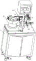
图1为本发明一种全自动溜光计数机实施例的立体结构示意图一;Fig. 1 is a three-dimensional structural schematic diagram of an embodiment of a fully automatic slip counting machine of the present invention;
图2为图1中A处的放大结构示意图;Fig. 2 is the schematic diagram of the enlarged structure of place A in Fig. 1;
图3为本发明一种全自动溜光计数机实施例的立体结构示意图二;Fig. 3 is a three-dimensional structural schematic diagram II of an embodiment of a fully automatic sliding light counting machine of the present invention;
图4为图3中E处的放大结构示意图;Fig. 4 is a schematic diagram of an enlarged structure at E in Fig. 3;
图5为本发明一种全自动溜光计数机实施例的剖视结构示意图一;Fig. 5 is a sectional structural schematic diagram 1 of an embodiment of a full-automatic sliding light counting machine of the present invention;
图6为图5中B处的放大结构示意图;Fig. 6 is a schematic diagram of the enlarged structure at B in Fig. 5;
图7为本发明一种全自动溜光计数机实施例的剖视结构示意图二;Fig. 7 is a schematic cross-sectional structure diagram II of an embodiment of a fully automatic sliding light counting machine of the present invention;
图8为图7中C处的放大结构示意图;FIG. 8 is a schematic diagram of an enlarged structure at C in FIG. 7;
图9为图7中D处的放大结构示意图;Fig. 9 is a schematic diagram of an enlarged structure at D in Fig. 7;
图10为本发明一种全自动溜光计数机实施例中芯轴的放大结构示意图;Fig. 10 is a schematic diagram of the enlarged structure of the mandrel in an embodiment of a fully automatic slip counting machine of the present invention;
主要元件符号说明如下:The main component symbols are explained as follows:
机柜1、振动盘2、料道21、直振动筛22、工作平台3、送料缸31、送料台32、红外线感应器33、第一滑槽台34、外环台4、定位台5、通孔51、第二滑槽台52、挤压缸6、挤压块61、压筒62、压孔63、芯轴7、圆台71、挡料板8、第三滑槽台81、落料缸82、抽屉9。Cabinet 1, vibrating
具体实施方式Detailed ways
为了使本领域的技术人员可以更好地理解本发明,下面结合附图和实施例对本发明技术方案进一步说明。In order to enable those skilled in the art to better understand the present invention, the technical solution of the present invention will be further described below in conjunction with the accompanying drawings and embodiments.
如图1~图10所示,本发明的一种全自动溜光计数机,包括机柜1和PLC处理器,机柜1上端面右侧设有振动盘2,振动盘2出料端连接有料道21,料道21下方设有直振动筛22,料道21 左侧设有工作平台3,工作平台3上端面设有第一滑槽台34,第一滑槽台34上端面设有从前至后的第一滑槽,第一滑槽内设有送料台32,第一滑槽台34后端面设有送料缸31,送料缸31前端设有送料杆,送料杆连接送料台32,工作平台3上端面还设有红外线感应器33,工作平台3 前端面设有外环台4,外环台4上端面中央设有外环孔,外环台4上端面设有定位台5,定位台5 上端面设有通孔51,定位台5上端面设有第二滑槽台52,第二滑槽台52后端面设有从上至下的第二滑槽,第二滑槽内设有挤压块61,第二滑槽台52上端面设有挤压缸6,挤压缸6下端设有挤压杆,挤压杆连接挤压块61,挤压块61下端面设有压筒62,压筒62外轮廓与通孔51相匹配,压筒62下端面设有压孔63,外环孔内设有芯轴7,芯轴7上部设有圆台71,圆台71顶端设有圆锥台,圆台71位于外环孔内,芯轴7下方设有挡料板8,机柜1上端面于挡料板8对应位置设有第三滑槽台81,第三滑槽台81上端面设有从左至右的第三滑槽,第三滑槽台81左端面设有落料缸82,落料缸82右端面设有落料杆,落料杆连接挡料板8,机柜1于挡料板8下方设有抽屉9,红外线感应器33输出端连接PLC处理器输入端,PLC处理器输出端分别连接送料缸31、挤压缸6 和落料缸82。As shown in Figures 1 to 10, a fully automatic slip counting machine of the present invention includes a cabinet 1 and a PLC processor, a
本实施例中,把产品倒入振动盘2,产品在振动盘2的作用下从出料端进入料道21,产品在直振动筛22的作用下进入工作平台3被红外线感应器33感应、并且把感应信号传入PLC处理器,PLC处理器计数并且控制送料缸31运动,向前推动产品至通孔51上方,并套入圆锥台然后 PLC处理器控制送料缸31复位,同时,PLC处理器控制挤压缸6运动,使压筒62下压,把产品压入外环孔并且套设在圆台71上,此时,圆台71通过产品与外环孔紧密配合,实现溜光处理,处理后的产品套在圆台71处,PLC处理器控制送料缸31继续推送产品,然后使用压筒62下压,使圆台71外壁滞留多个产品,当产品在圆台71外壁积累到一定数量时,产品脱离圆台71和外环孔在自身重力的作用下落到挡料板8上,此时,由于产品还套设在芯轴7上,产品在芯轴7 上积累,PLC处理器的计数达到一定数量时,控制落料缸82动作,使挡料板8向左运动,此时芯轴7上积累的产品在重力的作用下,掉入抽屉9,此时,由于芯轴7通过滞留在圆台处的一些产品和外环孔实现紧配合,故芯轴7不会掉落。这样的结构设计,产品外表面在通过外环孔时受到挤压,对产品外表面进行了溜光,产品内表面在通过圆台71时受到挤压,对产品内表面进行了溜光,当多个产品滞留在圆台71与外环孔之间时,压筒62对产品的上下端面均进行了压铸处理,大大降低了产品表面的粗糙度,而且避免了产品尖锐角被磨损的问题;同时由于使用全自动化设计,工人在调试好机器后,只需要把待处理的产品倒入振动盘2,然后隔一段时间从抽屉9里取走溜光完成的产品即可,大大减少了工人的劳动强度,而且具有计数功能,用此机器加工后的产品在收集时就已经计好数,不需要另外花时间数数。In this embodiment, the product is poured into the vibrating
优选,通孔51为十字形通孔。这样的结构设计,在压筒62向下运动挤压产品时,十字形通孔对压筒62起导向作用,防止压筒62把产品压偏,提高产品合格率。实际上,也可根据实际情况,具体考虑通孔51的形状。Preferably, the through
优选,圆台71和外环台4为硬质的耐磨材料制成。这样的结构设计,可延长圆台71和外环台4的使用寿命。实际上,也可根据实际情况,具体考虑。Preferably, the round platform 71 and the outer ring platform 4 are made of hard wear-resistant materials. Such a structural design can prolong the service life of the round platform 71 and the outer ring platform 4 . In fact, it can also be considered according to the actual situation.
优选,圆台71下端面设有第一螺纹孔,芯轴7上端设有与第一螺纹孔相匹配的第一外螺纹,圆台71上端面设有第二螺纹孔,圆锥台下端设有与第二螺纹孔相匹配的第二外螺纹。这样的结构设计,在实际使用时,由于圆台71的磨损最为严重,通过螺纹孔与外螺纹的配合,可拆卸连接,当圆台71磨损后,可只更换圆台71,减少成本支出。实际上,也可根据实际情况,具体考虑圆台71与芯轴7、圆锥台的连接方式。Preferably, the lower end surface of the circular platform 71 is provided with a first threaded hole, the upper end of the
优选,抽屉9为并排的两个。这样的结构设计,当一个抽屉9装满后,只需要更换一个抽屉9即可,不需要停止溜光计数机的运转,实用性更强。实际上,也可根据实际情况,具体考虑抽屉9的个数。Preferably, the drawers 9 are two side by side. Such structural design, when a drawer 9 is full, only need to change a drawer 9 and get final product, do not need to stop the operation of slip light counting machine, practicability is stronger. In fact, the number of drawers 9 can also be specifically considered according to the actual situation.
优选,机柜1底部设有轮子91。这样的结构设计,方便溜光计数机的运输,实用性更强。实际上,也可根据实际情况,考虑其他方便溜光计数机运输的结构设计。Preferably, the bottom of the cabinet 1 is provided with
优选,机柜1底部设有可升降支撑腿。这样的结构设计,在溜光计数机运输完成后,可伸长支腿,使轮子91离开地面,使用支腿支撑机柜1,防止机柜1移动。实际上,也可根据实际情况,考虑其他支撑机柜1的结构设计。Preferably, the bottom of the cabinet 1 is provided with liftable support legs. Such structural design, after the sliding light counting machine is transported, can extend supporting leg, makes
优选,挡料板8与落料缸82之间设有第一卡块,挡料板8上端面设有与第一卡块相匹配的第一凹槽,落料杆通过第一卡块与落料缸82连接。这样的结构设计,在安装时,可先把挡料板8放置在第三滑槽内,再把落料杆与第一卡块连接,最后从第一凹槽上方压入第一卡块,从而使落料杆与挡料板8连接,安装更加方便。实际上,也可根据实际情况,考虑其他方便安装的结构设计。Preferably, a first block is provided between the
优选,送料台32与送料缸31之间设有第二卡块,送料台32上端面设有与第二卡块相匹配的第二凹槽,送料杆通过第二卡块与送料缸31连接。这样的结构设计,在安装时,可先把送料台32放置在第三滑槽内,再把送料杆与第二卡块连接,最后从第二凹槽上方压入第二卡块,从而使送料杆与送料台32连接,安装更加方便。实际上,也可根据实际情况,考虑其他方便安装的结构设计。Preferably, a second clamping block is provided between the feeding
优选,送料台32下端面右侧设有缺口。这样的结构设计,在把产品向右推动时,把产品上端面压住,可使产品更好地套入圆锥台。实际上,也可根据实际情况,考虑其他可使产品更好地套入圆锥台的结构设计。Preferably, a gap is provided on the right side of the lower end surface of the
一种全自动溜光计数机使用方法,步骤如下:A method for using a fully automatic slip counting machine, the steps are as follows:
1).将不超过振动盘2容量(约3000~4000件)的产品倒入振动盘2并启动后,振动盘2 自动将产品排列好一个一个送往料道21;1). After pouring the products not exceeding the capacity of the vibrating plate 2 (about 3000-4000 pieces) into the vibrating
2).直振22进一步将料道21上的产品送往机器的中心部位;2). The
3).送料缸31和送料杆归位时,料道21送过来的产品能进入待送产品区并接受红外线感应器的感应;3). When the
4).红外线感应器感应到有产品过来后,送料缸31推动送料杆将产品送到待挤压区;4). After the infrared sensor detects that there is a product coming, the
5).送料缸31与送料杆复位后挤压缸6推动压筒62下压,将产品压入圆台71与外环孔的紧配合位置;5). After the
6).与此同时,料道21将下一个产品送达待送成品区,并重新接受红外线感应器的感应;6). At the same time, the
7).挤压缸6复位后送料缸31推动送料杆将产品送到待挤压区;7). After the
8).5~7工序循环多次后,最先压入圆台71与外环孔的紧配合位置的产品就完全经过了圆台71与外环的紧配合位置达到芯轴7下部,并滞留在这里;8). After the 5-7 process has been cycled many times, the product that is first pressed into the tight fit position between the round table 71 and the outer ring hole has completely passed through the tight fit position between the round table 71 and the outer ring to reach the lower part of the
9).5~7工序循环次数达到设定数量后,落料缸82拉动芯轴7下面的挡料板8回缩,滞留在芯轴7下部的产品全部落入接料盆里面,回缩到一定时间后复位;9). After the number of cycles in the 5-7 process reaches the set number, the blanking
以上对本发明提供的一种全自动溜光计数机进行了详细介绍。具体实施例的说明只是用于帮助理解本发明的方法及其核心思想。应当指出,对于本技术领域的普通技术人员来说,在不脱离本发明原理的前提下,还可以对本发明进行若干改进和修饰,这些改进和修饰也落入本发明权利要求的保护范围内。A full-automatic slip counting machine provided by the present invention has been introduced in detail above. The description of specific embodiments is only used to help understand the method and core idea of the present invention. It should be pointed out that for those skilled in the art, without departing from the principle of the present invention, some improvements and modifications can be made to the present invention, and these improvements and modifications also fall within the protection scope of the claims of the present invention.
Claims (7)
Priority Applications (1)
| Application Number | Priority Date | Filing Date | Title |
|---|---|---|---|
| CN201710322174.3A CN106938535B (en) | 2017-05-09 | 2017-05-09 | A fully automatic sliding light counting machine and its application method |
Applications Claiming Priority (1)
| Application Number | Priority Date | Filing Date | Title |
|---|---|---|---|
| CN201710322174.3A CN106938535B (en) | 2017-05-09 | 2017-05-09 | A fully automatic sliding light counting machine and its application method |
Publications (2)
| Publication Number | Publication Date |
|---|---|
| CN106938535A CN106938535A (en) | 2017-07-11 |
| CN106938535B true CN106938535B (en) | 2023-07-11 |
Family
ID=59463352
Family Applications (1)
| Application Number | Title | Priority Date | Filing Date |
|---|---|---|---|
| CN201710322174.3A Active CN106938535B (en) | 2017-05-09 | 2017-05-09 | A fully automatic sliding light counting machine and its application method |
Country Status (1)
| Country | Link |
|---|---|
| CN (1) | CN106938535B (en) |
Citations (9)
| Publication number | Priority date | Publication date | Assignee | Title |
|---|---|---|---|---|
| NO905236D0 (en) * | 1989-12-06 | 1990-12-04 | Pacific Wietz Gmbh & Co Kg | GAS LOCKING, CONTACT SEALING FOR A SHAFT. |
| JP2006036590A (en) * | 2004-07-27 | 2006-02-09 | Nippon Electric Glass Co Ltd | Glass article and method and apparatus for manufacturing the same |
| CN203067603U (en) * | 2012-12-24 | 2013-07-17 | 湖南吉利汽车部件有限公司 | Central valve type clutch master cylinder |
| CN103592218A (en) * | 2013-11-12 | 2014-02-19 | 哈尔滨工程大学 | Elastomer rubber sealing ring drag reduction test device and elastomer rubber sealing ring/non-smooth surface integrated drag reduction test device |
| CN204076769U (en) * | 2014-09-22 | 2015-01-07 | 阔丹—凌云汽车胶管有限公司 | Rubber tube processing die sleeve |
| CN104325373A (en) * | 2014-11-04 | 2015-02-04 | 苏州昌田机械设备制造有限公司 | Deburring device for blind hole in wheel rim |
| CN105014387A (en) * | 2015-08-05 | 2015-11-04 | 无锡市百事杰金属制品科技有限公司 | Soft metal strip edge chamfering machine |
| CN204987523U (en) * | 2015-09-25 | 2016-01-20 | 范沈江 | Water tank connector in formula solar energy of many storehouses |
| CN205463844U (en) * | 2016-03-31 | 2016-08-17 | 无锡格瑞斯精密机械有限公司 | Unhairing side forms utensil of ring gear |
Family Cites Families (18)
| Publication number | Priority date | Publication date | Assignee | Title |
|---|---|---|---|---|
| US4586223A (en) * | 1984-08-27 | 1986-05-06 | Kotaro Tsukamoto | Machine for straightening and polishing a round bar |
| CA2323779A1 (en) * | 1998-03-17 | 1999-09-23 | Stresswave, Inc. | Method and apparatus for producing beneficial stresses around apertures by the use of focused stress waves |
| US6225224B1 (en) * | 1999-05-19 | 2001-05-01 | Infineon Technologies Norht America Corp. | System for dispensing polishing liquid during chemical mechanical polishing of a semiconductor wafer |
| US6722964B2 (en) * | 2000-04-04 | 2004-04-20 | Ebara Corporation | Polishing apparatus and method |
| JP2003205456A (en) * | 2002-01-09 | 2003-07-22 | Matsushita Electric Ind Co Ltd | Hole processing method and ball burnishing device |
| US6923033B2 (en) * | 2003-10-02 | 2005-08-02 | Soave Enterprises, Llc | Roller system for flattening irregularly shaped, bent pieces of scrap sheet metal |
| US7036227B2 (en) * | 2004-02-06 | 2006-05-02 | David Ling | Process for making ratchet wheels |
| US7677289B2 (en) * | 2004-07-08 | 2010-03-16 | President And Fellows Of Harvard College | Methods and apparatuses for the automated production, collection, handling, and imaging of large numbers of serial tissue sections |
| CN201587012U (en) * | 2010-01-05 | 2010-09-22 | 海堡(厦门)橡胶有限公司 | Deburring device for sealing pieces |
| TWI674171B (en) * | 2012-01-31 | 2019-10-11 | 日商荏原製作所股份有限公司 | Substrate holding device, polishing device, and polishing method |
| CN102847784A (en) * | 2012-08-20 | 2013-01-02 | 吴江市三达五金工具厂 | Detachable-type deburring mechanism |
| CN103231294B (en) * | 2013-04-25 | 2016-04-06 | 苏州浦灵达自动化科技有限公司 | A kind of on-line automatic burr remover |
| CN203367724U (en) * | 2013-07-11 | 2013-12-25 | 厦门海普锐精密电子设备有限公司 | Bulk grain terminal crimping device |
| CN103787032A (en) * | 2014-02-28 | 2014-05-14 | 延锋伟世通(沈阳)汽车饰件系统有限公司 | Automatic quantifying feeder |
| CN104227143A (en) * | 2014-09-05 | 2014-12-24 | 宁波长华布施螺子有限公司 | Automatic slotting device for nut |
| CN205446919U (en) * | 2016-03-08 | 2016-08-10 | 新昌县新柴机械有限公司 | System movable valve element |
| CN105856560B (en) * | 2016-04-22 | 2019-05-21 | 深圳市沃尔核材股份有限公司 | A kind of end cap pyrocondensation molding machine |
| CN106426393B (en) * | 2016-07-07 | 2018-04-10 | 浙江翔宇密封件有限公司 | A kind of burr remover of sealing ring |
-
2017
- 2017-05-09 CN CN201710322174.3A patent/CN106938535B/en active Active
Patent Citations (9)
| Publication number | Priority date | Publication date | Assignee | Title |
|---|---|---|---|---|
| NO905236D0 (en) * | 1989-12-06 | 1990-12-04 | Pacific Wietz Gmbh & Co Kg | GAS LOCKING, CONTACT SEALING FOR A SHAFT. |
| JP2006036590A (en) * | 2004-07-27 | 2006-02-09 | Nippon Electric Glass Co Ltd | Glass article and method and apparatus for manufacturing the same |
| CN203067603U (en) * | 2012-12-24 | 2013-07-17 | 湖南吉利汽车部件有限公司 | Central valve type clutch master cylinder |
| CN103592218A (en) * | 2013-11-12 | 2014-02-19 | 哈尔滨工程大学 | Elastomer rubber sealing ring drag reduction test device and elastomer rubber sealing ring/non-smooth surface integrated drag reduction test device |
| CN204076769U (en) * | 2014-09-22 | 2015-01-07 | 阔丹—凌云汽车胶管有限公司 | Rubber tube processing die sleeve |
| CN104325373A (en) * | 2014-11-04 | 2015-02-04 | 苏州昌田机械设备制造有限公司 | Deburring device for blind hole in wheel rim |
| CN105014387A (en) * | 2015-08-05 | 2015-11-04 | 无锡市百事杰金属制品科技有限公司 | Soft metal strip edge chamfering machine |
| CN204987523U (en) * | 2015-09-25 | 2016-01-20 | 范沈江 | Water tank connector in formula solar energy of many storehouses |
| CN205463844U (en) * | 2016-03-31 | 2016-08-17 | 无锡格瑞斯精密机械有限公司 | Unhairing side forms utensil of ring gear |
Also Published As
| Publication number | Publication date |
|---|---|
| CN106938535A (en) | 2017-07-11 |
Similar Documents
| Publication | Publication Date | Title |
|---|---|---|
| CN203874825U (en) | Feeding control and deironing device of roller press | |
| CN106938535B (en) | A fully automatic sliding light counting machine and its application method | |
| CN206150320U (en) | Incomplete skin recovery system of dumpling | |
| CN206217210U (en) | The equipment for separating liquid from solid in kitchen field | |
| CN209614033U (en) | A kind of tooling for automatic blanking | |
| CN107486926A (en) | A kind of fully automatic hydraulic Dinas brickes brick machine | |
| CN204134925U (en) | A kind of color selector hopper | |
| CN210705716U (en) | Injection molding machine charging equipment | |
| CN204194278U (en) | The automatic medicine screening apparatus of a kind of primer | |
| CN104261024A (en) | Squeezing type bagging machine for garbage collection | |
| CN204235917U (en) | A kind of newtype drug tablet press machine | |
| CN204714684U (en) | A kind of High water cut material multi precompressed mechanical dehydration device | |
| CN109047354A (en) | A kind of pressure cone of the drawing with pressure cone guide block | |
| CN109501204A (en) | A kind of extruder with scrap iron removing function | |
| CN205820055U (en) | A kind of lower funnel of powder on quenelle | |
| CN104173191B (en) | A kind of comminutor | |
| CN210436674U (en) | Herbal pieces-flattens machine | |
| CN206718462U (en) | A kind of full-automatic very smooth counting machine | |
| CN111039736B (en) | Safe and reliable automatic explosive charging machine for primary explosive | |
| CN207310455U (en) | A kind of feeding device for recycling vehicle noise insulation pad plastic extruder | |
| CN105397054A (en) | Hammer lubricating device and method for ultra-large die casting machine | |
| CN209336156U (en) | A kind of grease molding machine | |
| CN204770659U (en) | Loading attachment of powder pressing pressure machine | |
| CN106076588A (en) | A kind of apparatus for separating metals | |
| CN205551097U (en) | High -efficient chain drawbench material collecting device |
Legal Events
| Date | Code | Title | Description |
|---|---|---|---|
| PB01 | Publication | ||
| PB01 | Publication | ||
| SE01 | Entry into force of request for substantive examination | ||
| SE01 | Entry into force of request for substantive examination | ||
| GR01 | Patent grant | ||
| GR01 | Patent grant | ||
| PE01 | Entry into force of the registration of the contract for pledge of patent right | ||
| PE01 | Entry into force of the registration of the contract for pledge of patent right |
Denomination of invention: A fully automatic slide counting machine and its usage method Granted publication date: 20230711 Pledgee: China Co. truction Bank Corp Dongguan branch Pledgor: DSH SEALS Co.,Ltd. Registration number: Y2025980011330 |