CN106923700B - Reducing mechanism and food preparation machine for food preparation machine - Google Patents
Reducing mechanism and food preparation machine for food preparation machine Download PDFInfo
- Publication number
- CN106923700B CN106923700B CN201511012671.0A CN201511012671A CN106923700B CN 106923700 B CN106923700 B CN 106923700B CN 201511012671 A CN201511012671 A CN 201511012671A CN 106923700 B CN106923700 B CN 106923700B
- Authority
- CN
- China
- Prior art keywords
- crushing
- fixed
- edge
- pushing
- material pushing
- Prior art date
- Legal status (The legal status is an assumption and is not a legal conclusion. Google has not performed a legal analysis and makes no representation as to the accuracy of the status listed.)
- Active
Links
- 235000013305 food Nutrition 0.000 title claims abstract description 60
- 230000007246 mechanism Effects 0.000 title claims abstract description 8
- 238000002360 preparation method Methods 0.000 title description 9
- 239000000463 material Substances 0.000 claims abstract description 385
- 238000010008 shearing Methods 0.000 claims description 36
- 238000012545 processing Methods 0.000 claims description 24
- XLYOFNOQVPJJNP-UHFFFAOYSA-N water Substances O XLYOFNOQVPJJNP-UHFFFAOYSA-N 0.000 claims description 17
- 230000009471 action Effects 0.000 claims description 15
- 230000030279 gene silencing Effects 0.000 claims description 15
- 239000000203 mixture Substances 0.000 claims description 11
- 238000009434 installation Methods 0.000 claims description 5
- 230000001154 acute effect Effects 0.000 claims description 3
- 230000003068 static effect Effects 0.000 claims description 2
- 244000068988 Glycine max Species 0.000 abstract description 35
- 235000010469 Glycine max Nutrition 0.000 abstract description 35
- 235000020124 milk-based beverage Nutrition 0.000 abstract description 5
- 239000013049 sediment Substances 0.000 abstract description 2
- 230000002829 reductive effect Effects 0.000 description 41
- 230000000694 effects Effects 0.000 description 33
- 238000000034 method Methods 0.000 description 29
- 235000013336 milk Nutrition 0.000 description 25
- 239000008267 milk Substances 0.000 description 25
- 210000004080 milk Anatomy 0.000 description 25
- 239000002002 slurry Substances 0.000 description 25
- 239000002245 particle Substances 0.000 description 24
- 244000046052 Phaseolus vulgaris Species 0.000 description 23
- 235000010627 Phaseolus vulgaris Nutrition 0.000 description 23
- 230000008569 process Effects 0.000 description 21
- 238000000227 grinding Methods 0.000 description 18
- 238000001914 filtration Methods 0.000 description 17
- 230000006870 function Effects 0.000 description 16
- 230000000903 blocking effect Effects 0.000 description 15
- 239000008187 granular material Substances 0.000 description 13
- 239000007788 liquid Substances 0.000 description 13
- 238000005520 cutting process Methods 0.000 description 12
- 238000001125 extrusion Methods 0.000 description 12
- 238000007790 scraping Methods 0.000 description 12
- 230000002349 favourable effect Effects 0.000 description 8
- 238000004519 manufacturing process Methods 0.000 description 8
- 230000009286 beneficial effect Effects 0.000 description 7
- 238000010298 pulverizing process Methods 0.000 description 7
- 238000011160 research Methods 0.000 description 7
- 238000010586 diagram Methods 0.000 description 6
- 239000010419 fine particle Substances 0.000 description 6
- 238000004537 pulping Methods 0.000 description 6
- 101100327917 Caenorhabditis elegans chup-1 gene Proteins 0.000 description 5
- 235000013361 beverage Nutrition 0.000 description 5
- 230000000875 corresponding effect Effects 0.000 description 4
- 238000004140 cleaning Methods 0.000 description 3
- 238000013461 design Methods 0.000 description 3
- 230000036541 health Effects 0.000 description 3
- 230000035807 sensation Effects 0.000 description 3
- 235000019615 sensations Nutrition 0.000 description 3
- 239000012141 concentrate Substances 0.000 description 2
- 230000035622 drinking Effects 0.000 description 2
- 238000010438 heat treatment Methods 0.000 description 2
- 230000006872 improvement Effects 0.000 description 2
- 238000002347 injection Methods 0.000 description 2
- 239000007924 injection Substances 0.000 description 2
- 230000005389 magnetism Effects 0.000 description 2
- 239000011268 mixed slurry Substances 0.000 description 2
- 230000036961 partial effect Effects 0.000 description 2
- 239000000843 powder Substances 0.000 description 2
- 238000005086 pumping Methods 0.000 description 2
- 230000009467 reduction Effects 0.000 description 2
- 239000002893 slag Substances 0.000 description 2
- 235000013322 soy milk Nutrition 0.000 description 2
- 238000005406 washing Methods 0.000 description 2
- 238000005303 weighing Methods 0.000 description 2
- 238000003466 welding Methods 0.000 description 2
- 238000005299 abrasion Methods 0.000 description 1
- 230000001133 acceleration Effects 0.000 description 1
- 230000003044 adaptive effect Effects 0.000 description 1
- 230000002411 adverse Effects 0.000 description 1
- 238000010923 batch production Methods 0.000 description 1
- 238000010009 beating Methods 0.000 description 1
- 230000008901 benefit Effects 0.000 description 1
- 230000009172 bursting Effects 0.000 description 1
- 238000005266 casting Methods 0.000 description 1
- 230000008859 change Effects 0.000 description 1
- 238000010276 construction Methods 0.000 description 1
- 235000013325 dietary fiber Nutrition 0.000 description 1
- 238000007599 discharging Methods 0.000 description 1
- 230000009977 dual effect Effects 0.000 description 1
- 238000004880 explosion Methods 0.000 description 1
- 235000015203 fruit juice Nutrition 0.000 description 1
- 239000011521 glass Substances 0.000 description 1
- 230000010354 integration Effects 0.000 description 1
- 239000010410 layer Substances 0.000 description 1
- 230000000670 limiting effect Effects 0.000 description 1
- 230000004048 modification Effects 0.000 description 1
- 238000012986 modification Methods 0.000 description 1
- 238000004321 preservation Methods 0.000 description 1
- 230000002035 prolonged effect Effects 0.000 description 1
- 230000001737 promoting effect Effects 0.000 description 1
- 238000000926 separation method Methods 0.000 description 1
- 210000004911 serous fluid Anatomy 0.000 description 1
- 239000002356 single layer Substances 0.000 description 1
- 238000005245 sintering Methods 0.000 description 1
- 235000013619 trace mineral Nutrition 0.000 description 1
- 239000011573 trace mineral Substances 0.000 description 1
- 230000009466 transformation Effects 0.000 description 1
- 238000012795 verification Methods 0.000 description 1
- 239000002699 waste material Substances 0.000 description 1
Images


Classifications
-
- A—HUMAN NECESSITIES
- A47—FURNITURE; DOMESTIC ARTICLES OR APPLIANCES; COFFEE MILLS; SPICE MILLS; SUCTION CLEANERS IN GENERAL
- A47J—KITCHEN EQUIPMENT; COFFEE MILLS; SPICE MILLS; APPARATUS FOR MAKING BEVERAGES
- A47J43/00—Implements for preparing or holding food, not provided for in other groups of this subclass
- A47J43/04—Machines for domestic use not covered elsewhere, e.g. for grinding, mixing, stirring, kneading, emulsifying, whipping or beating foodstuffs, e.g. power-driven
- A47J43/07—Parts or details, e.g. mixing tools, whipping tools
- A47J43/0705—Parts or details, e.g. mixing tools, whipping tools for machines with tools driven from the upper side
- A47J43/0711—Parts or details, e.g. mixing tools, whipping tools for machines with tools driven from the upper side mixing, whipping or cutting tools
-
- A—HUMAN NECESSITIES
- A47—FURNITURE; DOMESTIC ARTICLES OR APPLIANCES; COFFEE MILLS; SPICE MILLS; SUCTION CLEANERS IN GENERAL
- A47J—KITCHEN EQUIPMENT; COFFEE MILLS; SPICE MILLS; APPARATUS FOR MAKING BEVERAGES
- A47J43/00—Implements for preparing or holding food, not provided for in other groups of this subclass
- A47J43/04—Machines for domestic use not covered elsewhere, e.g. for grinding, mixing, stirring, kneading, emulsifying, whipping or beating foodstuffs, e.g. power-driven
- A47J43/044—Machines for domestic use not covered elsewhere, e.g. for grinding, mixing, stirring, kneading, emulsifying, whipping or beating foodstuffs, e.g. power-driven with tools driven from the top side
-
- A—HUMAN NECESSITIES
- A47—FURNITURE; DOMESTIC ARTICLES OR APPLIANCES; COFFEE MILLS; SPICE MILLS; SUCTION CLEANERS IN GENERAL
- A47J—KITCHEN EQUIPMENT; COFFEE MILLS; SPICE MILLS; APPARATUS FOR MAKING BEVERAGES
- A47J43/00—Implements for preparing or holding food, not provided for in other groups of this subclass
- A47J43/04—Machines for domestic use not covered elsewhere, e.g. for grinding, mixing, stirring, kneading, emulsifying, whipping or beating foodstuffs, e.g. power-driven
- A47J43/046—Machines for domestic use not covered elsewhere, e.g. for grinding, mixing, stirring, kneading, emulsifying, whipping or beating foodstuffs, e.g. power-driven with tools driven from the bottom side
-
- A—HUMAN NECESSITIES
- A47—FURNITURE; DOMESTIC ARTICLES OR APPLIANCES; COFFEE MILLS; SPICE MILLS; SUCTION CLEANERS IN GENERAL
- A47J—KITCHEN EQUIPMENT; COFFEE MILLS; SPICE MILLS; APPARATUS FOR MAKING BEVERAGES
- A47J43/00—Implements for preparing or holding food, not provided for in other groups of this subclass
- A47J43/04—Machines for domestic use not covered elsewhere, e.g. for grinding, mixing, stirring, kneading, emulsifying, whipping or beating foodstuffs, e.g. power-driven
- A47J43/07—Parts or details, e.g. mixing tools, whipping tools
- A47J43/0716—Parts or details, e.g. mixing tools, whipping tools for machines with tools driven from the lower side
- A47J43/0722—Mixing, whipping or cutting tools
Abstract
The invention relates to a kitchen appliance and a crushing component thereof, in particular to a crushing device for a food processor and the food processor with the same. This reducing mechanism for food processor is including deciding the ring gear, pushing away material spare and lid, the lid sets up in the one end of deciding the ring gear, and the lid surrounds with deciding the ring gear and form crushing chamber, it is located crushing intracavity to push away the material spare, and drives rotatoryly by the pivot, decide the ring gear and have a plurality of fixed teeth of arranging along circumference, two adjacent fixed teeth between be formed with the blown down tank. Compare in the kitchen rubbing crusher utensil among the prior art, this food processor rubbing crusher has overturned traditional blade formula crushing mode, adopts a high-speed high heart crushing mode that combines together through multiple crushing mode to come broken material, realizes making the real exempting from of soybean milk drink and strains no sediment, and the consumer drinks the smooth, fine and smooth taste.
Description
Technical Field
The invention relates to a kitchen appliance and parts thereof, in particular to a crushing device for a food processor and the food processor.
Background
With the continuous improvement of modern living standard, more and more people not only begin to pay attention to the requirements of health preservation and health, but also have more and more requirements on the taste quality of the health drink.
The traditional soybean milk machine, whether a household soybean milk machine or a commercial soybean milk machine, needs to be filtered after the soybean milk is made, the filtered soybean milk beverage has fine and smooth taste, and the soybean milk beverage has no granular sensation and is easy to enter the mouth when being drunk by a consumer. Meanwhile, the filtering of the soybean milk also brings great inconvenience to consumers, for example, the filtering procedure is complicated, the time consumption is long, and the filtering is not suitable for modern fast-paced life needs. Meanwhile, after filtration, the filter screen and the filter bowl need to be cleaned and cleaned, so that the workload after improvement is increased. In addition, the bean dregs filtered by the filter screen are difficult to treat, and the bean dregs are rich in dietary fibers and a plurality of trace elements beneficial to human bodies, so that waste is easily caused if the bean dregs are directly thrown away.
For a traditional household soybean milk machine, no matter what type of crushing system is adopted, the blade cutting type crushing is adopted, and materials are continuously collided with the crushing blade to be cut into fine particles by the crushing blade. According to researches, the particle size of the bean dregs without granular sensation is generally less than 100 microns when people drink the soybean milk, the average particle size of the bean dregs in the traditional household soybean milk machine blade crushing mode is more than 300 microns, and for a general soybean milk machine, when the water amount is 1200mL and the amount of dried soybeans is 80g, the bean dregs are filtered by a 50-mesh filter screen, the amount of the bean dregs is basically more than 100g, and the amount of the remaining bean dregs is large, so most consumers can meet the drinking requirements of smooth and delicate taste only by filtering. Even in the condition of the same water amount and the same dry soybean amount of a filter-free soybean milk machine sold in the market in recent years, the filter-free soybean milk machine still has bean dregs of more than 30g after being filtered by a filter screen of 50 meshes, and although the amount of the bean dregs is reduced, the filter-free soybean milk machine is suitable for the filter-free requirement of most consumers, the filter-free soybean milk machine still has granular feeling when being drunk by old people and children and still cannot meet the requirement of common consumers on the taste of beverages.
Disclosure of Invention
The invention aims to provide a smashing device for a food processing machine, which subverts the traditional blade-type smashing novel pulping structure, can really make soybean milk without filtering and has very high smashing efficiency.
In order to achieve the purpose, the invention adopts the following technical scheme: the utility model provides a reducing mechanism for food processing machine which characterized in that: including deciding the ring gear, pushing away material spare and lid, the lid sets up in the one end of deciding the ring gear, and the lid surrounds with deciding the ring gear and forms crushing chamber, it is located crushing intracavity to push away the material spare, and drives rotatoryly by the pivot, decide the ring gear and have a plurality of fixed teeth of arranging along circumference, two adjacent fixed teeth between be formed with the blown down tank, be located crushing intracavity, when the pivot drives and pushes away the material spare and rotate, push away the material and promote the mixture of material and water and be centrifugal motion, realize that the material is broken by fixed tooth to, the mixture of the material after being broken and water is discharged along the blown down tank under the effect of centrifugal force.
Furthermore, decide the tooth and include first edge, second edge and the fixed tooth face of connecting first edge and second edge, along the direction of rotation of pivot, first edge is located the place ahead of second edge to the pivot center is the centre of a circle, first edge and second edge are not on the same circle, and first edge is greater than second edge distance R2 to the centre of a circle to the distance R1 of centre of a circle.
Further, R1-R2 are more than or equal to 0.01mm and less than or equal to 0.2 mm;
or the fixed gear ring comprises a base body part, the fixed gear is fixed on the base body part, the fixed gear is a rectangular gear, and the rectangular gear is obliquely arranged relative to the center of the rotating shaft;
or the fixed tooth surface is a plane or a concave arc surface.
Furthermore, the pushing element comprises an installation part fixed on the rotating shaft and a pushing plate fixed on the installation part, and the pushing plate is parallel to the rotating shaft and is arranged in a protruding mode.
Furthermore, the average gap between the end part of the material pushing plate and the fixed teeth is L1, wherein the average gap is more than or equal to 0.1mm and less than or equal to L1 and less than or equal to 1 mm.
Further, the minimum width of the discharge chute is L2, wherein L2 is more than or equal to 0.1mm and less than or equal to 1 mm;
or the number of the material pushing plates is multiple, the effective length of a single material pushing plate is L3, the rotating radius of the material pushing piece is R, wherein L3/R is more than or equal to 0.15 and less than or equal to 0.8;
or the material pushing piece is of a disc-shaped structure, the material pushing plate is located at the edge of the disc, the material pushing plate is obliquely arranged on the material pushing piece, the central connecting line of two end parts of the material pushing plate is N1, the connecting line from the center of one end of the material pushing plate, which is far away from the rotating shaft, to the center of the rotating shaft is N2, the acute angle formed by N1 and N2 is alpha, and alpha is more than 0 and less than or equal to 60 degrees.
Furthermore, the crushing device also comprises a pre-crushing structure, and the pre-crushing structure is arranged in the crushing cavity.
Furthermore, the pre-crushing structure is a static knife which is arranged on the cover body and protrudes towards the material pushing part;
or the pre-crushing structure is a convex blade which is arranged on the pushing piece and protrudes towards the cover body;
or, the pre-crushing structure is arranged on the cover body and faces to the first shearing knife protruding from the material pushing part and is arranged on the material pushing part and faces to the second shearing knife protruding from the cover body, the first shearing knife and the second shearing knife are arranged in a staggered mode, and when the material pushing part rotates, the second shearing knife and the first shearing knife form shearing matching.
Further, a feed inlet is formed in the cover body, the area of the feed inlet is S, the volume of the crushing cavity is V, and S/V is more than or equal to 0.03/mm and less than or equal to 0.5 mm;
or a plurality of strip-shaped silencing grooves are formed in the cover body, the groove width of each strip-shaped silencing groove is L4, and L4 is larger than or equal to 0.5mm and smaller than or equal to 2 mm.
In addition, the invention also provides a food processor, which comprises a cup body and is characterized in that: the crushing device for the food processing machine is arranged in the cup body.
The working principle of the crushing device for the food processing machine is as follows: the rotating shaft drives the pushing piece to rotate at a high speed in the crushing cavity and is positioned in the crushing cavity, the pushing piece pushes a mixture of a material and water to do centrifugal motion, the material is pushed at a high speed by the pushing piece in the rotating process, under the action of centrifugal force, the material can impact the fixed teeth at a high speed and be sheared, cut and smashed by the fixed teeth, the material can also rub against the fixed teeth in the rotating process to form friction grinding and smashing, meanwhile, when the gap between the pushing piece and the fixed teeth is smaller than the original size of the material, the material can be sheared and extruded between the pushing piece and the fixed teeth to form shearing smashing and extruding smashing, the material is smashed by the fixed teeth to form fine particles under the common action of various acting forces, in addition, because a discharge chute is arranged between adjacent fixed teeth, when the pushing piece rotates, the pressure in the crushing cavity is increased, the mixture of the smashed material and the water can be ejected out of the discharge chute at a high speed, and at the in-process of outside injection, by the broken material granule of decide tooth can receive the extrusion and the friction of blown down tank inner wall, after the material cell constantly extrudees and rubs through the blown down tank inner wall, the material cell inner wall can be heated the inflation and take place to burst to tiny material granule can further obtain the breakage, and meanwhile, the material granule rubs with the inner wall of blown down tank, can form the friction and grind and smash, also can be further grind the breakage to tiny material granule.
The crushing device for the food processing machine adopts a novel crushing mode different from blade crushing, adopts the mode that the pushing piece rotates to push the materials to do centrifugal motion, leads the materials to be under the combined action of a plurality of crushing modes, does not participate in the direct crushing of the materials, only plays a role of assisting pushing, and realizes that the materials are crushed by the fixed teeth. Compare in current single blade cutting mode, can more effectual broken material, can be so that the material by more meticulous of broken, crushing efficiency is very high, reaches the effect of the perfect broken wall of material cell. In addition, the food processing machine with the crushing device for the food processing machine of the invention can produce soybean milk beverage which does not need to be filtered at all, has fine and smooth mouthfeel, has no granular feeling when being drunk by young people, old people and children and is easy to enter the mouth.
Drawings
The invention will be further described with reference to the accompanying drawings in which:
FIG. 1 is a schematic structural diagram according to a first embodiment of the present invention;
FIG. 2 is an enlarged schematic view at A in FIG. 1;
fig. 3, 4, 5, 6 and 7 are schematic structural views of the material pushing part;
FIG. 8 is a schematic structural view of the material pushing member engaged with the fixed gear ring;
FIG. 9 is an enlarged schematic view at B of FIG. 8;
FIG. 10 is a schematic view of the structure of the fixed ring gear;
FIG. 11 is a schematic view of a fixed tooth mounting arrangement;
FIG. 12 is another schematic view of the fixed ring gear;
FIG. 13 is an exploded view of the cover and the stationary ring gear;
FIG. 14 and FIG. 15 are schematic structural views of a pressure relief structure of a pulverizing chamber;
FIG. 16 is a schematic view of an alternative pressure relief structure;
FIG. 17 is a schematic structural diagram according to a second embodiment of the present invention;
FIG. 18 is an enlarged schematic view at C of FIG. 17;
FIG. 19 is an exploded view of the reducing assembly of FIG. 17;
FIG. 20 is a schematic view of a pre-crushing structure provided on the pusher;
FIG. 21 is a schematic view of another pre-crushing structure arranged on the pushing member;
FIG. 22 is a schematic view of a pre-crushing structure disposed on the cover;
FIG. 23 is a schematic view of a modified structure of the second embodiment;
FIG. 24 is an exploded view of the reducing assembly of FIG. 23;
FIG. 25 is a schematic view of the cover of FIG. 23;
FIG. 26 is a schematic structural diagram of a third embodiment of the present invention;
FIG. 27 is a schematic structural diagram according to a fourth embodiment of the present invention;
fig. 28 is a schematic structural view of the motor of fig. 27 mounted with a pusher.
Detailed Description
The first embodiment is as follows:
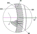
fig. 1 and fig. 2 are schematic structural diagrams of a first embodiment of the present invention. The utility model provides a food preparation machine, includes cup 1, is provided with reducing mechanism 2 for food preparation machine in the cup 1, and this reducing mechanism is including deciding ring gear 21, pushing away material piece 22 and lid 23, lid 23 sets up in the one end of deciding ring gear 21, and lid 23 and decide ring gear 21 and surround and form crushing chamber 20, pushing away material piece 22 is located crushing chamber 20, and drives rotatoryly by pivot 31, pushing away material piece 22 including pushing away the flitch 221, pushing away flitch 221 is located pushing away material piece 22 towards the protruding setting of lid 23 one end, decide ring gear 21 and have a plurality of fixed teeth 211 of arranging along circumference, be formed with blown down tank 210 between two adjacent fixed teeth 211.
In this embodiment, cup 1 below is provided with motor 3, pivot 31 runs through cup 1 and is connected with motor 3, decide ring gear 21 and be fixed in the bottom internal surface of cup 1, lid 23 is located the top of deciding ring gear 21, and fix as an organic whole with deciding ring gear 21, it communicates with each other with crushing chamber 20 to be located the feed inlet 230 that is provided with to run through on the lid 23, be located crushing chamber 20, when motor 3 drives pivot 31 high-speed rotatory, pivot 31 drives material pushing member 22 and rotates, material pushing plate 221 promotes the mixture of material and water and is centrifugal motion, it is broken by fixed tooth 211 to realize the material, and, the mixture of the material after being broken and water is spout along blown out chute 210 under the effect of centrifugal force.
The working principle of the food processor provided by the embodiment of the invention is as follows: during pulping, the crushing device for the food processing machine is immersed in liquid, when a motor drives a rotating shaft to rotate at a high speed, a pushing piece also rotates at a high speed and is positioned in a crushing cavity, a pushing plate on the pushing piece pushes a mixture of a material and water to do centrifugal motion, the material can impact fixed teeth at a high speed under the action of centrifugal force and is sheared, cut and crushed by the fixed teeth, the material can also rub with the fixed teeth along the surfaces of the fixed teeth in the rotating process to form friction grinding crushing, and meanwhile, when the gap between the pushing piece and the fixed teeth is smaller than the original size of the material, the material can be sheared and extruded between the pushing piece and the fixed teeth to form shearing crushing and extrusion crushing, and the material is crushed by the fixed teeth to form fine particles under the combined action of multiple acting forces. And, because the blown down tank has between the adjacent fixed tooth, when pushing away the material piece and rotating, the pressure increase of smashing the intracavity, the mixture of by broken material and water can spout crushing chamber through the blown down tank high speed, and at the in-process of outside injection, owing to receive the effect of smashing intracavity pressure and centrifugal inertia force, the extrusion can take place with the inner wall of blown down tank by broken material granule, the friction, after the blown down tank inner wall is continuous to the material granule extrudees and rubs, material cell inner wall can be heated the inflation and take place to burst, thereby tiny material granule can further obtain the breakage, meanwhile, material granule rubs with the inner wall of blown down tank, can form the friction and grind and smash, also can make tiny material granule obtain further grinding breakage. When the mixed slurry flow of material and water is jetted from the blown down tank, because the slurry flow velocity of flow is higher, the spun slurry flow can reflect, roll to the cup center after striking the cup lateral wall to be provided with the feed inlet on the lid, the slurry flow that reflects back can follow the feed inlet and get into crushing intracavity again, continues to participate in the breakage, and according to the continuous circulation breakage that carries on of above-mentioned mode.
According to the food processing machine, the prepared beverage is very fine in grinding fineness through the continuous circular crushing mode, the requirement that common consumers drink bean beverages without filtering pulp and residue can be really met, and the bean beverages are free of granular sensation and fine and smooth in taste when being drunk. The inventor finds that the food processor of the invention can crush more finely because the crushing device of the food processor of the invention adopts a novel crushing structure different from the prior one, mainly utilizes the high-speed rotation of the material pushing piece to drive the material pushing plate to push the material to do high-speed centrifugal rotation motion, so that the material is crushed and crushed in the crushing cavity under the combined action of various forces, such as shearing crushing, extrusion crushing, impact crushing, cutting crushing, friction grinding crushing, material cell thermal explosion crushing and the like. Compare in the single blade cutting formula of current domestic soybean milk machine and smash, and the single low-speed abrasive type of commercial soybean milk machine is smashed, the material pushing member of this embodiment does not participate in the direct crushing to the material, only provide propelling force to the material, it is broken by the fixed tooth to make the material, thereby can more effectual broken material, and, because the fixed tooth of this embodiment has a plurality ofly, and arrange around the fixed tooth circle, therefore, compare in prior art material and the probability increase of fixed tooth emergence effect, in addition, through the broken back of circulation many times, can make the material by broken more meticulous, crushing efficiency is very high.
As shown in fig. 3, in the present embodiment, the material pushing member 22 is a disc-shaped structure, the material pushing member 22 includes a mounting portion 220 fixed on the rotating shaft, a material pushing plate 221 is fixed on the disc-shaped mounting portion 220, the material pushing plate 221 is located at an edge of the mounting portion 220, the material pushing plate 221 extends from the edge of the disc to the center of the rotating shaft, wherein a distance height from the bottom of the material pushing member to the inner surface of the bottom of the cup body 1 is H3, and H3 is required to be at least greater than 0.2 mm. Because the pushing member 22 rotates at a high speed along with the rotating shaft 31, if the distance H3 is small, the friction between the pushing member 22 and the bottom wall of the cup body 1 is increased, which not only is noise easily generated and the probability of damage to the pulverizing device increased, but also increases the load of the pushing member 22, the motor may be burned out due to an excessive load, and meanwhile, the friction between the pushing member 22 and the cup body 1 may cause the temperature in the pulverizing cavity 20 to rise, and the scorching phenomenon is easily caused. For the pushing member of the present invention, H3 is generally not too large, because when H3 is too large, the volume of the clearance cavity 10 between the pushing member 22 and the cup body 1 will also increase, and the slurry in the clearance cavity 10 will not participate in the circulation, at this time, the pushing member of the disc structure needs to be structurally transformed, for example, the pushing member 22 needs to be provided with a through circulation diversion hole 222-1, and the slurry in the clearance cavity 10 can be guided into the crushing cavity 20 through the diversion hole 222-1 for circular crushing. For example, as shown in fig. 4, the pushing member 22 is designed to be a blade-like structure, and the structure thereof is that one end of the pushing plate 221 is fixed on the mounting portion 220, and the other end extends to the outside far from the mounting portion 220 to form a blade-like structure, at this time, a flow guiding notch 222-2 is formed between the blades, and the slurry in the clearance cavity 10 can enter the crushing cavity 20 through the flow guiding notch 222-2 to participate in the circular crushing. Of course, the distance (H3) between the pushing member of the blade-like structure and the bottom of the cup body is not too large, and is required to be at least more than 0.2 mm. In addition, in the invention, the connection between the material pushing plate and the mounting part can be an integrally formed structure, or can be fixedly integrated through mounting and matching.
It should be noted that the material pushing plate may be a continuous extending structure, for example, extending to the center of the rotating shaft, or may be an intermittent arrangement structure, for example, a gap is provided on the material pushing plate, or an intermittent gap is provided between the material pushing plate and the center of the rotating shaft. When the notch is arranged and the size of the notch is smaller than the original size of the material, the load of the pushing piece can be effectively reduced in the rotating process of the pushing piece, slurry flows can flow out through the notch, large materials cannot pass through the notch and are still pushed by the pushing plate to operate, so that the pushing load of the pushing plate on partial slurry is reduced, the load of the pushing piece is reduced, and the noise of the whole machine is further reduced. Of course, other designs can be provided for the structure which effectively reduces the load of the pushing piece and the noise of the whole machine. For example, as shown in fig. 4, the height of the material pushing plate is gradually reduced from outside to inside, which is advantageous in that: the load of the material pushing part can be reduced while more materials are broken. Because most materials receive the effect of centrifugal force and can keep away from the pivot center rotatory, and will keep away from the higher time of the high setting of the scraping wings at pivot center, be favorable to the scraping wings to promote more materials and participate in the breakage, and will be close to the lower time of the high setting of the scraping wings at pivot center, can reduce the effect of blockking the liquid flow of the scraping wings near the pivot to can reduce the load that the pushing parts bore. The structure of the material pushing plate with the height gradually reduced from outside to inside comprises a bottom plane and a top inclined plane; a bottom bevel, a top plane; and the bottom and the top are both of a slope structure and the like. For example, as shown in fig. 3, one end of the material pushing plate close to the center of the rotating shaft is made into a chamfer structure, and the structure has the same function as that in fig. 4, so that the load of the material pushing piece is reduced while material pushing is ensured. Of course, the arrangement and variation of this construction of the ejector plate can be adapted to other ejector configurations of the present invention.
It should be noted that the material pushing plate in this embodiment is mainly used for pushing the mixed slurry of the material and the water to do centrifugal motion, and the material pushing plate is more favorable for pushing the material to move, under the condition that the rotating speed of the motor is constant, the material slides along the side wall pushing surface of the pushing plate in the moving process of pushing the material by the pushing plate, because the linear velocity of each part of the pushing piece is increased along with the increase of the radius of the pushing piece, the pushing plate can accelerate the material in the process that the material slides along the pushing plate, thereby leading the material to have higher linear velocity to impact the fixed teeth, forming the crushing by the fixed teeth, the friction grinding crushing, the cutting crushing, and simultaneously, in the pushing process, when the gap between the pushing plate and the fixed teeth is smaller than the original size of the material, the pushing plate and the fixed teeth can also interact with each other to shear and extrude the material, so that the shearing, crushing and extruding crushing of the material are realized. In the rotating process of the pushing piece, the material can do centrifugal motion in the crushing cavity, so that the pushing plate is arranged at the edge of the pushing piece, and the pushing acceleration effect is more favorably realized. In order to enhance the pushing effect of the pushing plate, as shown in fig. 5, a chamfer 2210 may be further disposed on the edge of the pushing plate 221, and the chamfer 2210 needs to be disposed toward the rotation direction of the pushing element, so that the pushing area of the pushing plate can be increased, and the pushing plate can push more materials to move, and in addition, when the gap between the pushing element and the fixed teeth is small (as shown in fig. 8), when the pushing element rotates, an accommodating cavity 100 is formed between the chamfer 2210 and the fixed teeth 211, so that more materials can stay in the accommodating cavity 100 and can be pushed by the pushing plate 221 to move. Meanwhile, because chamfer 2210 is the bevel structure, the material can slide, lead to on deciding the tooth along the incline direction of chamfer, realize that the material strikes surely the tooth more easily, even the material strikes surely the tooth bounce-back, also can be towards the rebound in the holding chamber 100, consequently, holding chamber 100 still has the effect of gathering materials, has promoted the efficiency that the material was broken. Of course, the rear side of the material pushing plate can be provided with a chamfer, at the moment, the mass of the material pushing plate is reduced, the load of a material pushing part and a motor can be correspondingly reduced, and the noise of the whole machine is effectively reduced.
The material pushing plate in this embodiment may also be obliquely disposed on the material pushing member, as shown in fig. 6, the material pushing plate is located at the edge of the disc, and the material pushing plate is obliquely disposed on the material pushing member, wherein a central line of two end portions of the material pushing plate is N1, a line connecting a center of one end of the material pushing plate away from the rotating shaft to the center of the rotating shaft is N2, and an acute angle formed by N1 and N2 is α. The inventor finds out according to research that for the pushing element structure shown in fig. 6, if the pushing element rotates clockwise, α is required to be not less than 0 and not more than 45 degrees, because after the pushing plate is obliquely arranged, when α is more than 45 degrees, the pushing plate is easy to push the material to the center of the rotating shaft, and the material is not pushed to the direction of the fixed teeth, the material is not easy to be sheared and extruded by the pushing plate and the fixed teeth, and the material is not easy to collide to the fixed teeth due to the blocking of the pushing plate, so that the crushing, cutting and friction grinding effects of the fixed teeth on the material cannot be formed. Meanwhile, the inventor also finds that the pushing plate is obliquely arranged on the pushing piece, so that an unexpected effect can be brought, the pushing plate can guide liquid flow, the load applied to the pushing piece in the rotating process is reduced, the noise of the food processor is reduced, and according to the verification of the realization effect, when the alpha is more than or equal to 0 and less than or equal to 15 degrees, the comprehensive effect is better, wherein the alpha is = 0-5 degrees, and the effect is the best. In fig. 6, if the ejector pad is the anticlockwise rotation, when the ejector pad slope sets up, the ejector pad can lead the material, form similar helical blade structure, and under the effect of centrifugal force, the material slides and strikes the fixed tooth along the continuous direction in the side of ejector pad, thereby it is broken by the fixed tooth, at this moment, the alpha angle that forms should not too big yet, if alpha increase, rotatory in-process, the effective ejection face of ejector pad will reduce, be unfavorable for the propelling movement to the material, under this condition, general alpha requires to be less than 60. In the present invention, the lengths of the plurality of pushing plates provided on the pushing member may be equal or different, and are not limited to the structure described in the present embodiment. Of course, it should be noted that the pushing surface on the side surface of the pushing plate in the present invention may be disposed vertically to the horizontal plane, or may be disposed obliquely to the horizontal plane, and when the pushing surface is disposed obliquely to the horizontal plane, the pushing surface may be inclined downward relative to the horizontal plane and the pushing surface may be inclined upward relative to the horizontal plane. If for the first kind of structure, the material face that pushes away of downward sloping helps promoting the rotatory in-process of material, prevents that the material from colliding the scraping wings backward to upwards bounce-back to collapse out and smash the chamber outside, and the material face that pushes away of downward sloping can effectual inject the direction of material bounce-back, reduces the probability that the material collapses out and smashes the chamber. Meanwhile, the downward inclination of the pushing surface is not beneficial to the guiding of the slurry flow, so that the load borne by the pushing piece is increased, and the noise of the whole machine or the burning-out phenomenon of a motor can be possibly generated. Therefore, when the pusher surface is inclined downward, the angle of inclination with respect to the vertical plane is generally required to be less than 15 °. If for the second kind of structure, the face of pushing away the material that upwards slopes helps leading to the thick liquid stream, reduces the load that pushes away the material piece and bear, but simultaneously, when the material collided the face of pushing away the material, the face of pushing away the material also can lead to the material, at this moment, because the slope direction of material is towards the discharge gate on the lid to the material bounce-back along the direction of pushing away the face of material, easily burst out from the feed inlet on the lid, be unfavorable for the material to concentrate on crushing intracavity and smash, reduced crushing efficiency. Therefore, when the pushing surface is inclined upward, the inclination angle formed by the pushing surface and the vertical plane is required to be less than 10 degrees.
In addition, the inventor also finds that the more the pushing plates are arranged on the pushing piece, the larger the load of the motor is, so that for the invention, the pushing plates are generally arranged in an amount of 2-8 and are uniformly distributed, and the dynamic balance performance of the pushing piece during the rotation motion is better facilitated. Meanwhile, the inventor also finds that if the effective length of a single material pushing plate is L3 and the rotating radius of the material pushing piece is R, the requirement that L3/R is more than or equal to 0.15 and less than or equal to 0.8 is met, because if L3/R is less than 0.15, the rotating radius of the material pushing plate relative to the material pushing piece is smaller, the amount of the material in the crushing cavity is related to the volume of the crushing cavity, the volume of the crushing cavity is related to the rotating radius of the material pushing piece, and when L3 is smaller, the amount of the material pushed by the material pushing plate is smaller, the amount of the material crushed by the fixed teeth in the crushing cavity is reduced in unit time, and accordingly the efficiency of the material crushed is reduced, and at the moment, the crushing device needs longer crushing time to crush and crush. Meanwhile, the inventor also finds that the value of L3/R is not too large, L3 is too large, and when the value is infinitely close to the rotating radius R of the material pushing piece, the load of the motor is larger, the quality requirement on the motor is higher, the cost of the motor is increased, and the phenomenon of burning out is easy to occur. In addition, when the motor load is large, the resonance phenomenon of the food processor is easily caused along with large noise. It should be noted that the effective length L3 of the stripper plate refers to two concentric circles formed by taking the center of the rotating shaft as the center of a circle and the distances from the centers of the two ends of the stripper plate to the center of the rotating shaft as the radius, wherein the difference between the radii of the two concentric circles is the effective length of the stripper plate (L3). It should be noted that, for the present invention, the pushing plate may be straight, curved, streamline, zigzag, etc., as long as the pushing plate has the function of centrifugal pushing.
As shown in fig. 7, a ring of baffle 229 may be further disposed on the top of the material pushing plate, the baffle 229 connects the material pushing plates together, when the material pushing plate pushes the material to operate, the baffle 229 on the top of the material pushing plate may block the material from collapsing, effectively limiting the material to be pushed by the material pushing plate and to be crushed by the fixed teeth. At this moment, baffle and scraping wings structure as an organic whole, the baffle rotates along with the rotation of scraping wings, and the material gets into from the through-hole that the baffle center formed, and meanwhile, the lid also has the same function, and the lid has realized with the baffle that dual fender material concentrates kibbling effect, increases behind the baffle, and more materials can be promoted by the scraping wings and decide the tooth and take place the breakage, consequently, to this embodiment, when being provided with the baffle on the scraping wings, also can not need the lid, and at this moment, the baffle is equivalent to the lid. Of course, it should be noted that the baffle may be a continuous annular structure as shown in fig. 7, or may be an intermittent annular structure, so that the total weight of the pushing member is reduced, the cost is reduced, the load borne by the pushing member during operation is effectively reduced, and the pressure relief effect on the slurry in the crushing cavity is also achieved.
As shown in fig. 8 and 9, in this embodiment, the fixed tooth 211 includes a first edge 2111, a second edge 2112, and a fixed tooth surface 2113 connecting the first edge and the second edge, in the rotation direction of the rotation shaft, the first edge 2111 is located in front of the second edge 2112, the center of the rotation shaft is used as the center of the circle, the first edge 2111 and the second edge 2112 are not on the same circle, and the distance R1 from the first edge to the center of the circle is greater than the distance R2 from the second edge to the center of the circle.
The fixed tooth surface in the embodiment is a plane and is used for connecting a first edge and a second edge, because R1 is more than R2, the first edge of the previous fixed tooth is far away from the center of the rotating shaft, and the second edge of the next fixed tooth is closer to the center of the rotating shaft, therefore, a distance difference exists between the first edge and the second edge, when the material pushing plate pushes the material to rotate in the working process, the material slides towards the edge of the fixed tooth by clinging to the fixed tooth surface, because the distance difference exists between the two adjacent edges of the fixed tooth, the fixed tooth surface can guide and slide the material, when the material slides to the second edge of the fixed tooth, the second edge of the fixed tooth blocks the material, because the rotating speed of the material pushing plate pushing the material to do centrifugal motion is higher, the second edge shears and cuts the material in a high-speed state, and the material is simultaneously extruded and pushed by the material pushing plate, therefore, the material is crushed into fine particles by the edge of the fixed tooth and the pushing plate, and the crushed material can be simultaneously blocked by the second edge and can be ejected out of the crushing cavity along the discharge chute between the fixed teeth under the guiding action. In this embodiment, the first edge and the second edge are perpendicular to the horizontal plane, and of course, the first edge and the second edge may be inclined to the horizontal plane. When the first edge and the second edge are obliquely arranged, the material rotates at a high speed under the action of centrifugal force, and compared with the situation that the edge of the fixed tooth is vertical to the horizontal plane, the contact surface with the edge is smaller at the moment when the material impacts the edge of the fixed tooth. The inventor of the invention finds that when the inclination direction of the fixed tooth edge is opposite to the rotation direction of the rotating shaft, the crushing efficiency of the materials is higher, but at the same time, the load born by the material pushing piece is also increased greatly. And when the fixed tooth edge is obliquely arranged, the production and the manufacture of modern industry are not facilitated, and the cost is multiplied. The inventor has found, therefore, that the teeth are generally arranged at an angle of not more than 60 ° relative to the vertical plane when the teeth are generally arranged at an angle. For the invention, the width between the first edge and the second edge, namely the width of a single fixed tooth, is required to be between 0.3mm and 3.5mm, because the width of the fixed tooth is smaller than 0.3mm, the strength of the fixed tooth cannot be ensured, the fixed tooth is possibly broken in the process of high-speed impact of materials, the materials are difficult to manufacture technically, and the width of the fixed tooth is too wide and is larger than 3.5mm, under the condition of a certain diameter of a fixed tooth ring, the number of the fixed teeth is greatly reduced, so that the possibility of impact of the materials and the fixed teeth is reduced, and the probability of breakage of the materials by the fixed teeth is reduced. And if the number of the fixed teeth is the same, the fixed gear ring is required to have a larger inner diameter, so that the size of the pushing part and the rated load of the motor are correspondingly increased, the cost of the whole machine is increased more, and the popularization and application and batch production of common families are not facilitated.
It should be noted that the distance difference between the fixed tooth edges, i.e. R1-R2, is required to be 0.01mm or more and R1-R2 or less and 0.2mm or less for the embodiment of the present invention, and if R1-R2 are smaller and smaller than 0.01mm, the fixed tooth edges are difficult to perform the shearing and cutting functions on the material, and the material pushing plate is difficult to combine with the second edge to crush the material due to the smaller distance difference. In addition, R1-R2 cannot be too large, if the size of the particles is larger than 0.2mm, the particles of the materials crushed by the second edge of the fixed teeth are larger, the discharge chute is easy to be blocked by the larger particles of the materials, and in addition, the phenomena that the materials and the material pushing plate are blocked easily exist due to the fact that R1-R2 are too large. The inventor finds that the difference value of R1-R2 is closely related to the fineness of the crushed powder, and the smaller the value of R1-R2 is, the finer the crushed powder is. In general, in order to obtain a fineness of 50 μm, the values of R1-R2 should be between 0.03 and 0.05 mm; if the crushing fineness of 75 μm is to be finally obtained, the numerical value of R1-R2 is preferably 0.05-0.07 mm; the difference of R1-R2 with the optimal crushing fineness of 100 mu m is about 0.06-0.1 mm; the difference R1-R2 which is the best grinding fineness of 0.2mm is about 0.1-0.2 mm. Generally, R1-R2=0.01mm is difficult to satisfy in terms of manufacturing process, which determines that the pulverization fineness of 10 μm or less is difficult.
As shown in fig. 10, the fixed ring gear 21 according to the embodiment of the present invention includes a base portion 212, the base portion 212 is used to fix the fixed teeth 211, the fixed teeth may be directly formed on the base portion by wire cutting, or the fixed teeth may be integrally fixed around the base portion by other fixing methods such as welding, bonding, sintering, casting, etc., and the base portion may be fixed at both ends of the fixed teeth in order to enhance the fixing effect of the fixed teeth and increase the installation strength of the fixed teeth. For this embodiment, the base portion may be secured to the bottom interior surface of the cup by screws or other non-removable fastening means. Of course, in order to facilitate the detachment and cleaning, the base body portion may be fixed to the inner surface of the bottom of the cup body by a magnetic attraction manner or other fixing manners which are easily detachable. For the present invention, the first edge and the second edge of the fixed tooth forming the distance difference may also be formed by a rectangular tooth axially rotated with respect to the base body, i.e. as shown in fig. 11. Meanwhile, the structure of the tooth fixing surface is not limited to the planar structure in the present embodiment, and may be a concave circular arc surface structure. For the embodiment of the invention, the diameter of the fixed gear ring is 20 mm-120 mm, preferably 50 mm-90 mm, and the number of the fixed teeth is 30-500, preferably 100-300. For the invention, the number of the fixed teeth on the unit arc length (cm) of the fixed tooth ring is preferably 3-20.
The inventor also finds that the ratio of the inner diameter of the fixed gear ring to the height of the fixed gear is required to be in the range of 1/40-3/5, because the squat-shaped fixed gear ring structure is more beneficial to crushing materials.
According to the invention, the discharge grooves are formed between the fixed teeth, materials rotating at a high speed are crushed, cut, ground by friction and sheared by the fixed teeth to form fine material particles, and then the fine material particles are mixed with slurry and discharged out of the crushing cavity through the discharge grooves, but in the process that the material particles pass through the discharge grooves, material particle cells are extruded and rubbed by the discharge grooves, and are continuously extruded and rubbed with the inner walls of the discharge grooves, so that the inner walls of the material particle cells are heated and expanded, and the cells burst from the inside, and further crushing of the material particles is realized. Simultaneously, the effect of blown down tank still is used for exporting the mixture of the material of being broken in smashing the intracavity and water outside smashing the chamber, reduces the liquid pressure in smashing the intracavity and pushes away the operation load of material spare. Thus, there are certain requirements for the spout to be dimensioned. The inventor finds that the discharge chute is formed by the side walls of the adjacent fixed teeth at intervals, so that the minimum width of the discharge chute is required to be 0.1mm to L2 to 1 mm. Because the slurry flows through the discharge chute at the position of the minimum width of the discharge chute at the minimum flow rate, the slurry amount flowing out of the crushing cavity in unit time is limited. If L2 undersize, and be less than 0.1mm, then be located the unable quick outflow of thick liquid of smashing the intracavity, at this moment, the pressure that smashes the intracavity is great, the load that pushes away material spare and bear is great, the motor is easy to be burnt out because of the too big possibility of load, the noise value that food preparation machine produced is also great, and the thick liquid stream that is located smash the chamber outside also can't get into again and smash the intracavity and continue to participate in smashing because of smashing intracavity pressure great, thereby reducing the crushing efficiency of reducing grinding device, meanwhile, the minimum width undersize of blown down tank also causes easily to block up the blown down tank, be unfavorable for the user to wash, and also hardly satisfy less than 0.1mm industrial manufacturing precision. Similarly, if L2 is too large and larger than 1mm, the extrusion and friction between the material particles crushed by the fixed teeth and the inner wall of the discharge chute will be reduced, and the probability of bursting of the inner wall of the material particle cell due to heating will be greatly reduced. Therefore, the possibility that fine particle materials are not crushed in time, namely are discharged from the discharge chute is increased, and the fine particle materials are still not completely crushed even after being circulated for many times, so that bean blocks exist, and meanwhile, if the discharge chute is excessively large, the number of the fixed teeth of the crushing cavity with the corresponding volume is correspondingly reduced, so that the probability that the materials are crushed by the fixed teeth is greatly reduced, therefore, for the food processing machine provided by the invention, the L2 with the size of 0.1mm or more and the L2 with the size of 1mm or less are required to be within the range, the food processing machine provided by the invention has better circulating crushing efficiency, and according to research, the effect is better when the L2=0.1 mm-0.5 mm, and further the L2=0.15 mm-0.4 mm. It should be noted that, when the side walls of two adjacent fixed teeth in the invention are parallel, the widths of the discharge chutes are equal, and at this time, the minimum width of the discharge chute is the width of the discharge chute. Wherein, during actual design, the effect of the mode that the blown down tank generally designed interior little big outward is favorable to the smashing of material more to, when carrying out self-cleaning, the blown down tank is difficult to hide the sediment, hide dirty, convenient washing.
In addition, the length of the discharge chute also has an important influence on the invention. Because, when the blown down tank is shorter, the intensity of tooth is less strong singly, and the material of high-speed motion is probably hit the bits of broken glass in the twinkling of an eye and decides the tooth, and simultaneously, the blown down tank is shorter, also does not benefit to the extrusion and the friction effect that the inner wall of blown down tank goes on to the material granule, can not play corresponding effect to the further crushing of material granule. And if the blown down tank sets up longer, from smashing the high-speed spun thick liquid stream of intracavity, owing to receive the extrusion and the friction of blown down tank inner wall, and the energy attenuation appears by a wide margin to from unable realization self-loopa of blown down tank spun thick liquid stream reentrant crushing intracavity in the feed inlet of lid, be unfavorable for the circulation crushing effect of material. Therefore, the length of the discharge chute is required to be between 1.5mm and 10mm for the invention. For the present invention, the first edge and the second edge of the fixed teeth may be disposed in parallel or not, when the fixed teeth are disposed in non-parallel, the discharge chute formed by the adjacent fixed teeth is in a tapered structure, and the width dimension of the discharge chute will also change. Because, push away the material spare in this embodiment and be close to in the lower part of deciding the ring gear, when blown down tank lower part width is less, be favorable to deciding the broken material of tooth, blown down tank upper portion width is great, is favorable to smashing the intracavity thick liquid pressure release. According to research, the inventor finds that when the first edge and the second edge are of non-parallel structures, the taper angle formed by the first edge and the second edge is required to be 0-20 degrees, and when the taper angle is located in the range, the pressure of slurry in a crushing cavity can be effectively relieved on the premise of not influencing the material crushing efficiency, and the load borne by a material pushing piece is reduced.
For the invention, the matching structure of the material pushing piece and the fixed gear ring is one of the important structures of the invention.
For example, the pushing element of the present invention rotates relative to the fixed gear ring, so a certain gap needs to be provided between the pushing element and the fixed gear ring, wherein the average gap value between the pushing element and the fixed gear ring is set to L1 (i.e. the average gap value between the pushing plate and the second edge of the fixed gear), according to research, the smaller the L1 value is, the finer the fineness of the crushed material is, but at the same time, during the rotation process of the pushing element driven by the rotating shaft, due to the swinging of the rotating shaft and the dynamic balance of the pushing element, the pushing element may collide with the fixed gear during the operation process, and the abrasion and damage phenomena of the crushing device are likely to occur, and in modern industrial manufacturing, due to the limitation of manufacturing accuracy and the assembly tolerance and the assembly gap during the assembly process, it is difficult to achieve that L1 is smaller than 0.1mm during the actual production. In addition, the inventor also finds that the larger the L1 value is, the larger the fineness of the crushed material is, the larger the gap value between the pushing plate and the fixed teeth is, and the pushing and shearing matching of the pushing plate and the fixed teeth edges on the material cannot be realized, so that the requirement of the inventor for 50-mesh filtration without slag cannot be met. According to research, the inventor finds that for the invention, when the L1 is within the range of 0.1 mm-1 mm, the requirement of no slag in 50-mesh filtration which can be realized by the invention is basically met, and the grinding effect is better. Among them, L1 is more preferably 0.15mm to 0.4 mm.
For example, as shown in fig. 2, the effective height of the material pushing plate provided in the material pushing member of the present invention is H1, and the height of the fixed teeth is H2. For the invention, the pushing plate is positioned in the crushing cavity, and the bottom of the pushing plate is required to be at least flush with the bottom of the fixed teeth, because the pushing plate is required to be matched with the fixed teeth to realize extrusion crushing and shearing crushing of materials. It should be noted that the effective height H1 of the stripper plate is the average distance from the level of the bottom of the fixed teeth to the top surface of the stripper plate on the stripper member. That is, if the bottom of the pushing element is flush with the bottom of the fixed teeth and the top surface of the pushing plate is in a horizontal structure, the effective height H1 is the actual distance from the bottom of the pushing element to the top of the pushing plate, and if the top surface of the pushing plate is an inclined plane, the effective height is the average height of the bottom of the pushing element from the top inclined plane of the pushing plate. Of course, for the fixed gear ring with the base body, the material pushing plate can be located partially within the height of the base body, and the function of the present invention can also be achieved, and at this time, the effective height H1 of the material pushing plate is still the average value of the distance from the position where the material pushing plate is flush with the bottom of the fixed gear to the top surface of the material pushing plate. The inventor of the present invention found that there is a certain relationship between H1 and H2, and if H1/H2 is increased, that is, close to 1, the matching surface between the pushing plate and the fixed teeth is increased, and the crushing amount and the crushing effect on the material are also increased, but at the same time, the actual height of the pushing plate is increased, and the load borne by the pushing piece is also increased, at this time, the load of the motor is increased, so that the motor burnout phenomenon easily occurs, and at the same time, the motor idling phenomenon easily occurs, and at this time, the noise of the whole machine is also large, which affects the normal pulping operation of consumers. In addition, H1/H2 cannot be too small, and if the size is too small, the matching surface between the pushing plate and the fixed teeth is reduced, and the effect of crushing the materials is also reduced. According to the research, the inventor finds that the food processor can basically meet the filter-free and slag-free requirements of the invention when the ratio of 1/3 to H1/H2 to 5/6 is not more than 1/3, wherein the comprehensive effect is better when the ratio of H1/H2= 0.4-0.6.
To this embodiment, the lid encloses with deciding the ring gear and forms crushing chamber, and the lid is hugged closely in the top fixed surface who decides the ring gear, and the lid can be strengthened deciding the tooth top, can prevent to decide the tooth and be struck the rupture by the material, can have the multiple to the fixed mode of lid and deciding the ring gear, for example the lid passes through the screw, welds, bonds to and modes such as integrated into one piece are fixed, realize lid and decide the undetachable structure of ring gear. Certainly, also can fix through lid and the detachable structure mode of deciding the ring gear, for example, lid and deciding the ring gear and pass through magnetism and inhale, the screw thread closes soon, the mode such as spiral shell is fixed, realizes dismantling the washing after the slurrying. The cover body is used for surrounding the fixed gear ring to form a crushing cavity, materials can be limited in the crushing cavity to be crushed in a centralized mode, the materials have certain hardness, when the materials are pushed by the pushing piece to move at a high speed, the materials are prone to being rebounded under the blocking effect of the pushing piece and the fixed gear ring, the materials can be blocked back into the crushing cavity by the cover body, the materials can continuously participate in centrifugal motion, and the materials are crushed by the fixed gear. Therefore, the cover body has the function of stopping materials and centralizing the materials in the crushing cavity for crushing.
Of course, other structural forms can be adopted for the structure which can lead the material to be collected in the crushing cavity for crushing.
For example, as shown in the structure of fig. 7, when the cover body is not provided, the baffle and the fixed gear ring surround to form a crushing cavity, the baffle rotates along with the pushing piece, and meanwhile, the baffle has the same material blocking effect as the cover body, so that the material can be concentrated in the crushing cavity to be crushed, and at the moment, the baffle is the cover body.
For example, as shown in fig. 12, the fixed gear ring is a conical structure, the top of each fixed tooth of the fixed gear ring is provided with a material blocking portion 2110 protruding toward the center, the material blocking portions 2110 are arranged along the circumference of the fixed gear ring, in the structure, the crushing cavity is formed by the inner wall of the fixed gear ring and the material blocking portions in a surrounding manner, when the pushing member rotates, materials rebound, the material blocking portions 2110 can block the materials back into the crushing cavity to be crushed by the fixed teeth, and crushed material particles enter the crushing cavity along with slurry from the feed inlet at the top of the material blocking portions 2110 to continuously participate in the circular crushing, in the structure shown in fig. 12, the material blocking portions and the fixed teeth are integrally formed, through grooves are arranged among the material blocking portions, the through grooves between the through grooves and the fixed teeth are communicated, the through grooves and the discharge grooves have different functions, the through grooves between the material blocking portions are mainly used for pressure relief, and the slurry pressure in the crushing cavity can be discharged out of the crushing cavity through the, the load of the material pushing part can be effectively reduced, and for the structure, the material blocking part 2110 has the same function as the cover body, so that under the structure, the same function of the invention can be realized even without the cover body, and at the moment, the material blocking part is the cover body. When the fixed gear ring is arranged in a conical shape, the edge of the pushing piece can be manufactured into a structure which is adaptive to the conical degree of the fixed gear. It should be noted that, for the structure shown in fig. 12, the fixed gear ring may be only a cone-shaped structure or the fixed gear ring may only have a material blocking portion instead of a cover body, so that the centralized crushing and material blocking functions of the present invention can be realized, and the material can be prevented from being collapsed, which is not described herein one by one.
In addition, it should be noted that, when the fixed gear ring is in a straight barrel structure or an inverted cone structure, if the height of the fixed gear is large enough relative to the rotation diameter of the pushing member, the top of the fixed gear ring may not be provided with a cover structure, because the material is pushed by the pushing member to bounce, and the material cannot break out of the crushing cavity formed by the fixed gear ring because the whole height of the fixed gear ring is high, the material still falls back into the crushing cavity after bouncing, and is pushed by the pushing member and crushed by the fixed gear. At the moment, the fixed gear ring is thin and high, and the ratio of the height of the fixed gear ring to the rotating diameter of the pushing piece is at least larger than 0.9, so that the material is not easy to collapse out of the crushing cavity.
In the case of the cover body in this embodiment, as shown in fig. 13, a feeding hole 230 is provided at the center of the cover body, through which the slurry outside the crushing cavity 20 can enter the crushing cavity to participate in crushing again, so that the material can circulate inside and outside the crushing cavity, and the efficiency of crushing the material is further improved. It should be noted that, a plurality of feeding holes may be provided, which is not limited to the center of the cover body in this embodiment, but the center of the cover body is more favorable for the material to be concentrated in the crushing cavity for crushing, because if the feeding holes are provided near the edge of the cover body, the material collided in the crushing cavity may jump out from the feeding holes near the edge of the cover body due to the rebound because the material performs centrifugal motion along with the material pushing member. For the embodiment, the area of the feeding hole is S (the minimum area of the cross section of the feeding hole), the inner volume of the crushing cavity formed by the surrounding of the cover body and the fixed gear ring is V, wherein S/V is required to be more than or equal to 0.03/mm and less than or equal to 0.5/mm. Because the S/V is too small and is less than 0.03/mm, the slurry flow positioned outside the crushing cavity cannot enter the crushing cavity in time to participate in crushing, a blank beating phenomenon may exist on a pushing piece positioned in the crushing cavity, and the material crushing efficiency is reduced. And S/V should not too big yet, and be greater than 0.5/mm, when S/V was too big, the material that is located crushing intracavity when crushing intracavity, can be ceaselessly bounce in crushing intracavity, probably pop out from the feed inlet even, is unfavorable for the concentrated crushing of material. The inventor finds that, for the embodiment, the horizontal distance between the inner wall of the fixed gear ring and the edge of the feed port is required to be at least larger than 1mm, so that the materials can be centralized in the crushing cavity and can be crushed, and the materials cannot be ejected from the feed port.
In fig. 13, a plurality of silencing grooves 231 are arranged on the cover body and around the edge of the feed inlet, wherein the width of a single silencing groove is L4, and L4 is required to be not less than 0.5mm and not more than 2mm, when the width of the silencing groove is within the range, the silencing groove can reduce the pressure of the crushing cavity and reduce the operation load of the pushing part and the motor, and the slurry in the crushing cavity can be discharged out of the crushing cavity through the silencing groove under the action of the pressure, so that the noise generated by overlarge load of the motor is reduced, therefore, the silencing groove also has the function of relieving the pressure of the slurry in the crushing cavity, and the effective circulation of the slurry is ensured. If the silencing groove is too wide, the material is not beneficial to being intensively crushed, and if the silencing groove is too narrow, the functions of pressure relief and noise reduction can not be achieved. Certainly, the silencing groove structure can also be arranged on the pushing piece, and when the pushing piece is provided with the silencing groove or the silencing seam, the loads borne by the pushing piece and the motor can be effectively reduced, so that the function of reducing noise can be achieved.
Similarly, in this embodiment, if it is desired to effectively release the pressure in the pulverization chamber, another pressure release structure may be provided in the pulverization chamber.
As shown in fig. 14 and 15, the pressure relief structure is a pressure relief notch 213-1 formed in the top of the fixed gear ring, the number of the pressure relief notches may be one or more, and after the cover body and the fixed gear ring surround to form a crushing cavity, a gap may be formed between the top of the fixed gear ring and the cover body, and in the process that the pushing member drives the slurry to rotate, because the pressure in the crushing cavity is too high, a part of the pressure in the crushing cavity may be discharged through the pressure relief notch, thereby reducing the load borne by the pushing member and the motor and facilitating noise reduction. Generally, the size of the pressure relief notch is smaller than 5mm, so that large-particle materials cannot be ejected from the pressure relief notch in the process of crushing the materials. Of course, the pressure relief notch may also be disposed on the cover body and located at the edge of the joint of the fixed gear ring and the cover body, or the fixed gear ring and the cover body are simultaneously provided with corresponding pressure relief notches.
The pressure relief structure may also be as shown in fig. 16, that is, the cover and the fixed gear ring surround to form a non-closed crushing cavity, and a gap is formed between the cover and the fixed gear ring to form a pressure relief gap 213-2. Because the pressure relief gap 213-2 is formed between the cover body and the fixed gear ring, in the pulping process, part of the serous fluid in the crushing cavity can be discharged through the pressure relief gap, so that the pressure in the crushing cavity is timely reduced, and the load born by the material pushing part and the motor is reduced. It should be noted that, for the structure, the height of the pressure relief gap is H4, and H4 is required to be less than or equal to 3mm, because if the pressure relief gap is too large, a large material may be ejected out of the crushing cavity through the pressure relief gap during pulping, which is not beneficial to centralized crushing of the material. Generally, H4 is preferably 0.5 mm-1.5 mm, and not only the material is more finely crushed, but also the noise value is lower. During the practical application, can design into elastic connection between lid and the decide ring gear, when smashing intracavity pressure when too big, the thick liquid that is located smashing the intracavity can jack-up lid and decide the ring gear separation to discharge through the lid and the pressure release gap of deciding between the ring gear, thereby effectively reduce the pressure of smashing the intracavity, reduce the load that pushes away material spare and motor, reduced food preparation machine's noise.
The inventor of the present invention utilized the food processor having the structure of the present embodiment to experimentally prepare soybean milk, and filtered and weighed the prepared soybean milk according to different rotation speeds of the motor, so as to obtain different experimental data results, as shown in tables 1 and 2:
table 1: experimental data of filtering and weighing soybean milk prepared from 80g of dry soybeans

Table 2: experimental data of filtering and weighing soybean milk prepared from 120g of wet soybeans
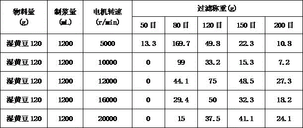
In the experimental result, the prepared soybean milk was subjected to superimposed filtration by using 50 mesh, 80 mesh, 120 mesh, 150 mesh and 200 mesh filtration screens under the same material amount and water amount, and after standing for 20 minutes, the soybean dregs obtained by filtration by using 50 mesh, 80 mesh, 120 mesh, 150 mesh and 200 mesh filtration were weighed.
According to the analysis of the experimental results, the inventor finds that the properties of the materials have great influence on the crushing result, the dry materials are easier to crush, the dry materials have higher hardness, the crushing such as extrusion, shearing, collision, cutting and friction and the like in the food processing machine can be more easily realized, the materials have stronger toughness and stronger viscosity after being soaked, and the crushing effect of extrusion, shearing, collision and cutting in the food processing machine is slightly poor. Furthermore, the inventor finds that the quantity of the filtered bean dregs is reduced by times if the crushing time is prolonged after the materials are soaked.
Table 3: relationship between filtering mesh number and bean dregs granularity
| Number of |
20 | 30 | 40 | 50 | 60 | 80 | 100 | 120 | 140 | 200 |
| Particle size (. mu.m) | 840 | 590 | 420 | 297 | 250 | 178 | 150 | 124 | 104 | 74 |
According to the relation table of the filter mesh number and the bean dregs granularity, the invention can find that no dregs exist basically after being filtered by a filter screen with 50 meshes, the average grain size of the bean dregs is less than 300 mu m, and the amount of the bean dregs after being filtered by 80 meshes is small, and the average grain size of the bean dregs is less than 178 mu m, so that even if a small amount of the bean dregs exist after being filtered by 80 meshes, the taste of general consumers is not influenced basically, and the bean dregs are still smooth and fine and are easy to be drunk.
The inventor also finds that for the invention, if the rotating speed of the motor is lower than 5000r/min, more bean dregs exist after being filtered by the filter screen of 50 meshes, and the aim of drinking without filtering can not be fulfilled for consumers, therefore, for the invention, the rotating speed of the motor is required to be at least 5000 r/min. Meanwhile, the inventor also finds that the grinding effect of the invention can be greatly improved by increasing the rotating speed of the motor, but at the same time, the cost of the motor is increased, the loss is higher, and the noise generated by the motor is increased. Therefore, the rotating speed of the motor is preferably 8000r/min to 30000r/min in consideration of the crushing effect and adverse factors. It should be noted that the time for making soybean milk by the food processing machine of the embodiment of the invention is shorter than the time for making soybean milk by a blade grinding type soybean milk machine in the prior art, and because the motor has higher rotating speed and shorter time for grinding materials, a hot soybean milk beverage can be quickly made within 10 minutes generally, and meanwhile, the grinding efficiency is higher, the grinding fineness is finer, and the beverage taste is finer and smoother and more smooth.
It should be noted that the transformation and parameter selection of the above-described structure in this embodiment can be applied to other embodiments of the present invention.
Example two:
fig. 17, 18 and 19 are schematic structural views of a second embodiment of the present invention. In the first embodiment, because the gap between the pushing member and the fixed teeth is small, and the gap between the discharging grooves between the fixed teeth is also small, the large material is difficult to be extruded and sheared by the pushing member and the fixed teeth, and particularly for the material with high hardness, the large material is easy to be ejected out of the crushing cavity after being impacted by the pushing member, so that the large material is difficult to be completely crushed. Therefore, in order to achieve the crushing effect of the present invention, for the first embodiment, it is necessary to perform pre-crushing on the large materials, coarsely crush the large materials into smaller material particles, and then place the material particles in the crushing cavity for fine crushing. However, such operations are relatively complicated and not convenient for the consumer. Therefore, in this embodiment, in addition to the first embodiment, the crushing apparatus is provided with the preliminary crushing structure, and the large material is preliminarily coarsely crushed by the preliminary crushing structure, and fine material is finely crushed simultaneously with the coarse crushing, so that the automatic integration of the coarse crushing and the fine crushing of the food processor is realized.
In this embodiment, the pre-crushing structure is arranged in the crushing cavity, the pre-crushing structure comprises a first shearing knife 25 which is arranged on the pushing member and protrudes towards the cover body and a second shearing knife 26 which is arranged on the cover body and protrudes towards the pushing member, the first shearing knife 25 and the second shearing knife 26 are arranged in a staggered manner, and in the rotating process of the pushing member, the first shearing knife 25 and the second shearing knife 26 form shearing cooperation with the material.
In crushing intracavity, through the shearing cooperation of shearing sword and second shearing sword, the bold material can be sheared into less material granule in advance, then less material granule through the scraping wings propelling movement that sets up on the pushing part again with decide extrusion of tooth, shearing and with deciding the collision of tooth, cutting, realize the broken of material and smash.
Of course, the pre-crushing structure in this embodiment may also have other structures, for example, as shown in fig. 20, the material pushing member is a blade-shaped structure, the pre-crushing structure is a blade 25-1 disposed on a blade of the material pushing member, the blade 25-1 is perpendicular to the material pushing plate, the blade 25-1 cuts and crushes the large material to form smaller material particles, and then the material pushing plate pushes the smaller material particles to cooperate with the fixed teeth, so that the material is crushed and crushed.
For another example, as shown in fig. 21, the pushing member is a disc-shaped structure, the pre-crushing structure is a convex blade 25-2 disposed on a disc of the pushing member, and the convex blade 25-2 protrudes toward the cover body and is distributed at the center of the disc. In the process of high-speed rotation of the pushing piece, the convex edge scrapes and grinds large materials, so that the large materials are coarsely crushed into fine material particles.
For example, as shown in fig. 18 and 22, the pre-crushing structure may also be a stationary knife 26-1 disposed on the cover body, the stationary knife 26-1 protrudes toward the pushing element, the pushing element rotates at a high speed to drive the material to move, and when the material collides with the stationary knife 26-1, the material is crushed into smaller material particles, which can also perform a coarse crushing function. It should be noted that the stationary knife is preferably arranged on the cover body at the edge of the crushing cavity and above the material pushing plate, because when the material pushing member drives the material to move, the material is in centrifugal motion, and the edge arranged on the crushing cavity is favorable for improving the probability of collision between the material and the stationary knife, meanwhile, the stationary knife can also form shearing and grinding cooperation with the material pushing plate, and can also improve the efficiency of coarse crushing of the material.
Through set up crushing structure in advance on reducing mechanism, the crushing efficiency of promotion material that can be great, simultaneously, also can accelerate food preparation machine's slurrying time. It should be noted that the above-mentioned pre-pulverization structures may be combined in various ways, and are not limited to the above-mentioned structures. And, the structure of smashing in advance also can set up in crushing chamber outsidely, for example, install crushing blade on the pivot, utilize crushing blade to carry out coarse crushing and also can play corresponding effect.
On the basis of this embodiment, the present inventors further modified the crushing apparatus as shown in fig. 23, 24, and 25. Be provided with the structure of guide cylinder 27 in the top of feed inlet, guide cylinder 27 has both made things convenient for placing of material, at the in-process of pulping, can also prevent that the bold material from collapsing out the crushing chamber outside from the feed inlet, promote the pressure release function in crushing chamber, can also set the guide cylinder into the grid form (shown structure in the figure promptly), when crushing chamber pressure is too big, the grid through feed inlet and guide cylinder that partial thick liquid can be quick is from smashing the chamber blowout, can effectively reduce the pressure of smashing the intracavity, and also can prevent simultaneously that the bold material from spouting crushing extraluminal, the concentrated kibbling function in crushing chamber has been improved. In addition, the inventor also arranges a grating ring 28 on the cover body and towards the pushing element, the grating ring 28 is arranged between the convex edge 25-2 on the pushing element and the pushing plate 221, the grating ring 28 is used for concentrating large materials and coarsely crushing the large materials by the convex edge 25-2 to realize concentrated coarse crushing of the large materials, when the materials are coarsely crushed into smaller particles, the smaller material particles pass through the grating holes 281 of the grating ring 28 to enter the edge of the crushing cavity due to the action of centrifugal force, and are extruded, sheared, rubbed, cut and the like with the fixed teeth under the pushing action of the pushing plate 221. Because the material is firstly subjected to centralized rough crushing operation, the load born by the material pushing part and the motor is greatly reduced, the material is crushed, and the noise of the whole machine is reduced. And after the materials are intensively coarsely crushed, the crushing fineness of the finely crushed materials is more uniform.
Through set up concentrated crushing structure on the basis of this embodiment, more be favorable to the steady operation of motor, both promoted the crushing homogeneity of material, also reduced the noise of complete machine. It should be noted that, the centralized crushing structure can be integrated with the cover body, and can also be detached from the cover body in a detachable manner, so that the cleaning is convenient. And variations of the above-described structure may be applied to other embodiments of the present invention.
Example three:
fig. 26 is a schematic structural diagram of a third embodiment of the present invention. The difference from the above embodiment is that: for the embodiment, the crushing device for food processing machine of the invention is mounted on the food processing machine with the motor on, the food processing machine comprises the cup body 1 and the machine head 4 positioned above the cup body 1, the motor 3 is mounted in the machine head 4, like the above-mentioned embodiment, in the embodiment, the fixed gear ring 21 is fixed at the bottom of the cup body 1, the cover body 23 is fixed at the top of the fixed gear ring, the feed inlet 230 is arranged at the center of the cover body 23, and the motor shaft, i.e. the rotating shaft, penetrates through the feed inlet 230 and is fixedly connected with the pushing member 22 in the crushing cavity.
The present embodiment has the same slurry circulation manner and the same beneficial effects as the above embodiments, and is not described herein again, and the structural changes and parameter selections adopted in the above embodiments can also be fully applied.
Example four:
fig. 27 and 28 are schematic structural views of a fourth embodiment of the present invention. This embodiment is another embodiment of the food processor in which the food processor-use grinding apparatus of the present invention is mounted on a motor. The food processor comprises a cup body 1 and a machine head 4 positioned above the cup body 1, wherein a motor 3 is arranged in the machine head 4, the machine head comprises a machine head upper cover (not shown in the figure) and a machine head lower cover 41, and the food processor is different from the food processor in the third embodiment in that: in this embodiment, the fixed gear ring 21 is directly fixed to the bottom of the head lower cover 41, the cover body is the head lower cover, the crushing cavity 20 is formed by surrounding the outer surface of the bottom of the head lower cover and the fixed gear ring 21, the motor shaft is a rotating shaft, the motor shaft extends into the crushing cavity 20 and is fixedly connected with the pushing piece 22, the bottom of the fixed gear ring 21 is open, the open portion of the bottom of the fixed gear ring is a feed inlet, when the motor shaft drives the pushing piece to rotate, the pushing piece pulls slurry into the crushing cavity from the open portion of the bottom of the fixed gear ring, the pushing piece pushes the material entering the crushing cavity and the fixed gear to perform crushing actions such as extrusion, shearing, friction, grinding, cutting and the like, and under the action of centrifugal force, the crushed material is ejected out of the crushing cavity from a discharge chute between the fixed gears.
In this embodiment, decide ring gear accessible magnetism inhale or the mode of turnbuckle is fixed in aircraft nose lower cover bottom, realize deciding dismantling of ring gear fixed, make things convenient for consumer's dismantlement to wash, certainly, decide ring gear also can be fixed as an organic whole with the aircraft nose lower cover, including fixing through screw or other modes to and process into an organic whole structure through welding etc.. And to this embodiment, decide the ring gear bottom and open, the material needs can enter into crushing intracavity when pushing away the material piece and rotating, consequently, generally pushes away and need set up the water conservancy diversion breach that can make things convenient for the material to enter on the material piece. And, the scraping wings is protruding towards the aircraft nose lower cover and sets up, consequently, pushes away the material piece and has very powerful pumping action at the pivoted in-process, and the material can be inhaled crushing intracavity like this, and at this moment, the scraping wings also has pumping part's effect. Unlike the previous embodiments, the circulation direction of the slurry is different in this embodiment, but the beneficial effects are the same, and are not described herein again.
In this embodiment, a separate cover member may be disposed on the top of the fixed gear ring, and in this case, the cover may be fixed to the lower cover of the machine head or directly fixed to the motor shaft. When the cover body is fixed on the motor shaft, the cover body does not rotate along with the motor shaft, at most, the cover body and the fixed gear ring are driven to rotate along with the rotation of liquid flow, and the rotation speed difference between the cover body and the motor shaft is large. It should be noted that, when the crushing device for a food processor of the present invention is applied to a food processor with a motor disposed thereon, the food processor may be a soymilk grinder with a double-layer lower cover structure, or a soymilk grinder with a single-layer lower cover structure.
The food processor of the present invention may have or may not have a heating device, and may produce soybean milk, other bean drinks, fruit juice, and the like.
It will be appreciated by those skilled in the art that the present invention includes, but is not limited to, those illustrated in the accompanying drawings and described in the foregoing detailed description. Any modification which does not depart from the functional and structural principles of the present invention is intended to be included within the scope of the claims.
Claims (9)
1. The utility model provides a reducing mechanism for food processing machine which characterized in that: the cover body is arranged at one end of the fixed gear ring, the cover body and the fixed gear ring are encircled to form a crushing cavity, the pushing part is located in the crushing cavity and is driven to rotate by a rotating shaft, the fixed gear ring is provided with a plurality of fixed teeth arranged along the circumferential direction, a discharge chute is formed between every two adjacent fixed teeth, the fixed teeth are located in the crushing cavity, when the rotating shaft drives the pushing part to rotate, the pushing part pushes a mixture of materials and water to do centrifugal motion, the materials are crushed by the fixed teeth, the mixture of the crushed materials and the water is discharged along the discharge chute under the action of centrifugal force, each fixed tooth comprises a first edge, a second edge and a fixed tooth surface connecting the first edge and the second edge, the first edge is located in front of the second edge along the rotating direction of the rotating shaft, the center of the rotating shaft is used as the center of a circle, the first edge and the second edge are not located on the same circle, and the distance R1 from the first edge to the center of the circle is greater than the distance R2 from the second edge to the center of the circle.
2. The reducing apparatus for food processing machines of claim 1, wherein: wherein, R1-R2 are more than or equal to 0.01mm and less than or equal to 0.2 mm;
or the fixed gear ring comprises a base body part, the fixed gear is fixed on the base body part, the fixed gear is a rectangular gear, and the rectangular gear is obliquely arranged relative to the center of the rotating shaft;
or the fixed tooth surface is a plane or a concave arc surface.
3. The reducing apparatus for food processing machines of claim 1, wherein: the material pushing piece comprises an installation part fixed on the rotating shaft and a material pushing plate fixed on the installation part, and the material pushing plate is arranged in parallel to the rotating shaft in a protruding mode.
4. The reducing apparatus for food processing machines according to claim 3, wherein: the average gap between the end part of the material pushing plate and the fixed teeth is L1, wherein the average gap is more than or equal to 0.1mm and less than or equal to L1 and less than or equal to 1 mm.
5. The reducing apparatus for food processing machines according to claim 3, wherein: the minimum width of the discharge chute is L2, wherein L2 is more than or equal to 0.1mm and less than or equal to 1 mm;
or the number of the material pushing plates is multiple, the effective length of a single material pushing plate is L3, the rotating radius of the material pushing piece is R, wherein L3/R is more than or equal to 0.15 and less than or equal to 0.8;
or the mounting part is of a disc-shaped structure, the material pushing plate is located at the edge of the disc, the material pushing plate is obliquely arranged on the mounting part, the central connecting line of the two end parts of the material pushing plate is N1, the connecting line from the center of one end of the material pushing plate, which is far away from the rotating shaft, to the center of the rotating shaft is N2, the acute angle formed by N1 and N2 is alpha, and alpha is more than 0 and less than or equal to 60 degrees.
6. The crushing apparatus for food processing machines according to any one of claims 1 to 5, wherein: the crushing device further comprises a pre-crushing structure, and the pre-crushing structure is arranged in the crushing cavity.
7. The reducing apparatus for food processors of claim 6, wherein: the pre-crushing structure is a static knife which is arranged on the cover body and protrudes towards the material pushing part;
or the pre-crushing structure is a convex blade which is arranged on the pushing piece and protrudes towards the cover body;
or, the pre-crushing structure is arranged on the cover body and faces to the first shearing knife protruding from the material pushing part and is arranged on the material pushing part and faces to the second shearing knife protruding from the cover body, the first shearing knife and the second shearing knife are arranged in a staggered mode, and when the material pushing part rotates, the second shearing knife and the first shearing knife form shearing matching.
8. The crushing apparatus for food processing machines according to any one of claims 1 to 5, wherein: the cover body is provided with a feed inlet, the area of the feed inlet is S, the volume of the crushing cavity is V, and S/V is more than or equal to 0.03/mm and less than or equal to 0.5/mm;
or the cover body is provided with a plurality of strip-shaped silencing grooves, the width of each strip-shaped silencing groove is L4, and L4 is more than or equal to 0.5mm and less than or equal to 2 mm.
9. A food processor, includes the cup, its characterized in that: a comminution device for a food processor as claimed in any one of claims 1 to 8 is provided in the cup body.
Priority Applications (1)
| Application Number | Priority Date | Filing Date | Title |
|---|---|---|---|
| CN201511012671.0A CN106923700B (en) | 2015-12-31 | 2015-12-31 | Reducing mechanism and food preparation machine for food preparation machine |
Applications Claiming Priority (1)
| Application Number | Priority Date | Filing Date | Title |
|---|---|---|---|
| CN201511012671.0A CN106923700B (en) | 2015-12-31 | 2015-12-31 | Reducing mechanism and food preparation machine for food preparation machine |
Publications (2)
| Publication Number | Publication Date |
|---|---|
| CN106923700A CN106923700A (en) | 2017-07-07 |
| CN106923700B true CN106923700B (en) | 2021-04-09 |
Family
ID=59458614
Family Applications (1)
| Application Number | Title | Priority Date | Filing Date |
|---|---|---|---|
| CN201511012671.0A Active CN106923700B (en) | 2015-12-31 | 2015-12-31 | Reducing mechanism and food preparation machine for food preparation machine |
Country Status (1)
| Country | Link |
|---|---|
| CN (1) | CN106923700B (en) |
Families Citing this family (4)
| Publication number | Priority date | Publication date | Assignee | Title |
|---|---|---|---|---|
| CN107321445B (en) * | 2017-08-30 | 2023-06-13 | 四川绿矿环保科技有限公司 | Rotary extrusion crusher |
| CN111728505B (en) * | 2020-05-11 | 2022-04-05 | 九阳股份有限公司 | Food preparation machine that cleaning performance is good |
| CN114468804B (en) * | 2020-10-28 | 2023-04-11 | 广东美的白色家电技术创新中心有限公司 | Grinding assembly |
| CN115318422B (en) * | 2022-09-02 | 2023-12-26 | 徐州徐工矿业机械有限公司 | Method for treating iron passing of gyratory crusher |
Citations (6)
| Publication number | Priority date | Publication date | Assignee | Title |
|---|---|---|---|---|
| CN101438941A (en) * | 2008-10-31 | 2009-05-27 | 江南大学 | Food material-pulverizing device based on incision principle |
| CN101693220A (en) * | 2009-10-01 | 2010-04-14 | 江南大学 | Crushing head device used for high-efficient shearing fine crusher |
| CN202021077U (en) * | 2010-12-20 | 2011-11-02 | 无锡赫普轻工设备技术有限公司 | Wet ultrafine grinding equipment for fiber material |
| CN202365650U (en) * | 2011-10-21 | 2012-08-08 | 九阳股份有限公司 | Grinder convenient for discharging |
| CN202760086U (en) * | 2012-06-25 | 2013-03-06 | 九阳股份有限公司 | Micro-grinding soybean milk machine |
| CN104545460A (en) * | 2015-01-04 | 2015-04-29 | 浙江绍兴苏泊尔生活电器有限公司 | Smashing device and soybean milk machine with same |
Family Cites Families (1)
| Publication number | Priority date | Publication date | Assignee | Title |
|---|---|---|---|---|
| DE102010039720B4 (en) * | 2010-08-24 | 2014-04-30 | BSH Bosch und Siemens Hausgeräte GmbH | Device for treating a material to be processed |
-
2015
- 2015-12-31 CN CN201511012671.0A patent/CN106923700B/en active Active
Patent Citations (6)
| Publication number | Priority date | Publication date | Assignee | Title |
|---|---|---|---|---|
| CN101438941A (en) * | 2008-10-31 | 2009-05-27 | 江南大学 | Food material-pulverizing device based on incision principle |
| CN101693220A (en) * | 2009-10-01 | 2010-04-14 | 江南大学 | Crushing head device used for high-efficient shearing fine crusher |
| CN202021077U (en) * | 2010-12-20 | 2011-11-02 | 无锡赫普轻工设备技术有限公司 | Wet ultrafine grinding equipment for fiber material |
| CN202365650U (en) * | 2011-10-21 | 2012-08-08 | 九阳股份有限公司 | Grinder convenient for discharging |
| CN202760086U (en) * | 2012-06-25 | 2013-03-06 | 九阳股份有限公司 | Micro-grinding soybean milk machine |
| CN104545460A (en) * | 2015-01-04 | 2015-04-29 | 浙江绍兴苏泊尔生活电器有限公司 | Smashing device and soybean milk machine with same |
Also Published As
| Publication number | Publication date |
|---|---|
| CN106923700A (en) | 2017-07-07 |
Similar Documents
| Publication | Publication Date | Title |
|---|---|---|
| CN106923700B (en) | Reducing mechanism and food preparation machine for food preparation machine | |
| CN204378902U (en) | Food processor | |
| CN203493439U (en) | Soybean milk machine | |
| CN102188159A (en) | Soybean milk machine | |
| CN106923703B (en) | Reducing mechanism and food preparation machine for food preparation machine | |
| CN107319964B (en) | Reducing mechanism and food preparation machine for food preparation machine | |
| CN109602299B (en) | Soybean milk machine | |
| CN205568787U (en) | Soybean milk machine | |
| CN108309087B (en) | Reducing mechanism and food preparation machine for food preparation machine | |
| CN102188158B (en) | Soybean milk machine | |
| CN108309086B (en) | Food processing machine | |
| CN208755781U (en) | Fine grinding device assembly and movable grinding piece thereof | |
| CN206700068U (en) | A kind of soy bean milk making machine | |
| CN106264129B (en) | Crushing assembly for soybean milk machine and soybean milk machine with same | |
| CN206700061U (en) | A kind of soy bean milk making machine | |
| CN206792307U (en) | A kind of food processing machine reducing mechanism and its food processor | |
| CN202135650U (en) | Soybean milk machine | |
| CN207341664U (en) | A kind of food processor | |
| CN108236407B (en) | Soybean milk machine | |
| CN108236408B (en) | Soybean milk machine | |
| CN218622446U (en) | Garbage disposal device | |
| CN111195547A (en) | Feed powder making device | |
| CN205885327U (en) | Food processor | |
| CN204889741U (en) | Food processor | |
| CN214317844U (en) | Cup body for food processing machine and food processing machine using cup body |
Legal Events
| Date | Code | Title | Description |
|---|---|---|---|
| PB01 | Publication | ||
| PB01 | Publication | ||
| SE01 | Entry into force of request for substantive examination | ||
| SE01 | Entry into force of request for substantive examination | ||
| GR01 | Patent grant | ||
| GR01 | Patent grant |