CN106906911B - Steel truss jacking ball point integral rotating device, jacking system and construction method - Google Patents
Steel truss jacking ball point integral rotating device, jacking system and construction method Download PDFInfo
- Publication number
- CN106906911B CN106906911B CN201710300454.4A CN201710300454A CN106906911B CN 106906911 B CN106906911 B CN 106906911B CN 201710300454 A CN201710300454 A CN 201710300454A CN 106906911 B CN106906911 B CN 106906911B
- Authority
- CN
- China
- Prior art keywords
- jacking
- steel
- net rack
- steel net
- rotating device
- Prior art date
- Legal status (The legal status is an assumption and is not a legal conclusion. Google has not performed a legal analysis and makes no representation as to the accuracy of the status listed.)
- Active
Links
Images



Classifications
-
- E—FIXED CONSTRUCTIONS
- E04—BUILDING
- E04B—GENERAL BUILDING CONSTRUCTIONS; WALLS, e.g. PARTITIONS; ROOFS; FLOORS; CEILINGS; INSULATION OR OTHER PROTECTION OF BUILDINGS
- E04B1/00—Constructions in general; Structures which are not restricted either to walls, e.g. partitions, or floors or ceilings or roofs
- E04B1/35—Extraordinary methods of construction, e.g. lift-slab, jack-block
- E04B1/3511—Lift-slab; characterised by a purely vertical lifting of floors or roofs or parts thereof
-
- E—FIXED CONSTRUCTIONS
- E04—BUILDING
- E04B—GENERAL BUILDING CONSTRUCTIONS; WALLS, e.g. PARTITIONS; ROOFS; FLOORS; CEILINGS; INSULATION OR OTHER PROTECTION OF BUILDINGS
- E04B1/00—Constructions in general; Structures which are not restricted either to walls, e.g. partitions, or floors or ceilings or roofs
- E04B1/35—Extraordinary methods of construction, e.g. lift-slab, jack-block
- E04B1/355—Extraordinary methods of construction, e.g. lift-slab, jack-block characterised by the tilting up of whole buildings or sections thereof, e.g. walls, portal frames
Landscapes
- Engineering & Computer Science (AREA)
- Architecture (AREA)
- Physics & Mathematics (AREA)
- Electromagnetism (AREA)
- Civil Engineering (AREA)
- Structural Engineering (AREA)
- Conveying And Assembling Of Building Elements In Situ (AREA)
Abstract
A steel mesh frame jacking ball point integral rotating device, a jacking system and a construction method are disclosed, wherein the steel mesh frame jacking ball point integral rotating device comprises a base, a support frame arranged on the base and a clamp member clamped on the support frame; the base comprises a horizontal bottom plate and two vertical plates which are connected to the bottom plate in parallel at intervals; the support frame comprises a support ring and a support rod connected to the opposite side of the support ring; the supporting rod is clamped in the first clamping groove in the vertical plate on the corresponding side and can rotate in the first clamping groove; the two hoop members are respectively connected to the tops of the two vertical plates and are clamped above the supporting rod; the clamp piece is including vertical clamp plate and the connecting rod of connection in clamp plate bottom surface both sides. The invention solves the technical problems of difficult variable angle jacking, difficult control of the inclination angle, high construction cost and longer construction period of the traditional steel net frame structure.
Description
Technical Field
The invention relates to a steel truss jacking ball point integral rotating device, a jacking system and a construction method, which are used during steel truss integral jacking high-altitude variable-angle construction.
Background
With the increasingly pursuit of aesthetic requirements of people, the structural requirements of stadiums are high, and the deformed steel net rack is also a characteristic of the development direction of sports careers. The prior rigid net rack is assembled in blocks, lifted and scattered in high altitude. But the steel net rack assembled in blocks, lifted and scattered in high altitude has high cost and long construction period. Therefore, the variable-angle jacking tool for the steel net rack ball points, which is provided by the invention, has the advantages of turnover, flexible arrangement, simplicity in installation, low manufacturing cost, firmness and durability, and is very necessary for the variable-angle jacking tools for the steel net rack ball points with different diameters, so that the construction period and the construction cost can be greatly saved.
Disclosure of Invention
The invention provides a steel truss jacking ball point integral rotating device, a jacking system and a construction method, and aims to solve the technical problems that a traditional steel truss structure is difficult to jack at variable angles, the inclination angle is difficult to control, the construction cost is high, and the construction period is long.
The technical scheme of the invention is as follows.
A steel truss jacking ball point integral rotating device comprises a base, a support frame arranged on the base and a clamp member clamped on the support frame; the base comprises a horizontal bottom plate and two vertical plates which are connected to the bottom plate in parallel at intervals; the middle of the top of each vertical plate is provided with a vertical first clamping groove, and the first clamping grooves on the two vertical plates correspond to each other; connecting blind holes are respectively formed in the top surface of the vertical plate and positioned on two sides of the first clamping groove; the supporting frame is horizontally arranged at the top of the base, and two ends of the supporting frame are respectively connected with the two vertical plates; the support frame comprises a support ring and a support rod connected to the opposite side of the support ring; the supporting rod is clamped in the first clamping groove on the vertical plate on the corresponding side and can rotate in the first clamping groove; the two clamping hoop members are respectively connected to the tops of the two vertical plates and clamped above the supporting rod; the hoop component comprises a vertical hoop plate and connecting rods connected to two sides of the bottom surface of the hoop plate; the distance between the connecting rods is equal to the distance between the connecting blind holes on the top surface of the vertical plate, and the connecting rods are correspondingly inserted in the connecting blind holes; and a second clamping groove corresponding to the first clamping groove is formed between the bottom surface of the clamp plate and the connecting rods positioned at the two sides.
Preferably, the first clamping groove is a semicircular clamping groove, and the second clamping groove is a semicircular clamping groove; the first clamping groove and the second clamping groove are spliced into a circular hoop, and the supporting rod hoop is arranged in the circular hoop.
Preferably, the bottom plate and the vertical plate are both made of steel plates, and the bottom plate and the vertical plate are connected in a welding mode; the supporting ring and the supporting rod are both made of steel rod pieces and are connected with each other in a welding mode; the clamp plate is made of a steel plate, the connecting rod is made of a steel rod piece, and the clamp plate and the connecting rod are connected in a welding mode.
A jacking system containing a steel net rack jacking ball point integral rotating device comprises a steel net rack, a lifting device and a fixed ball pivot point device; the steel net rack is gradually inclined upwards from the edge to the middle, and the edge of the steel net rack is connected with the main body structure; the method is characterized in that: the two lifting devices are correspondingly arranged below the two spherical nodes of the steel net rack along the inclination direction of the steel net rack; the steel mesh frame jacking ball point integral rotating device is arranged at the top of the lifting device close to one side of the edge of the steel mesh frame; the fixed ball pivot device is arranged at the top of the lifting device close to one side of the middle part of the steel mesh frame; the spherical nodes are respectively supported on a support frame of the steel mesh frame jacking ball point integral rotating device and the top of the fixed ball pivot device.
Preferably, the lifting device comprises a hydraulic jack and a jacking tower fixedly connected to the top of the hydraulic jack; through holes are arranged on a bottom plate of the steel mesh frame jacking ball point integral rotating device at intervals, and the steel mesh frame jacking ball point integral rotating device is connected with the jacking tower frame through bolts penetrating through the through holes.
Preferably, the fixed ball pivot device comprises a vertical steel plate support with a cross-shaped horizontal section and a horizontal connecting plate connected to the bottom of the vertical steel plate support; the top edge of the vertical steel plate support is gradually inclined downwards from the end part to the middle part to form a groove matched with the spherical node; the spherical joint close to one side of the middle part of the steel mesh frame is detachably connected with the fixed ball pivot device.
Preferably, the diameter of the spherical node is larger than that of the supporting ring on the supporting frame; the spherical node close to one side of the edge of the steel net rack is supported on the supporting ring of the supporting frame and can rotate on the supporting ring.
A construction method of a jacking system comprising a steel truss jacking ball point integral rotating device comprises the following steps.
Step one, manufacturing the steel truss jacking ball point integral rotating device, which comprises a base, a support frame and a hoop.
Step two, installing a lifting device; the two lifting devices are arranged along the inclined direction of the steel mesh frame to be installed, and the distance between the two lifting devices is equal to the distance between two adjacent spherical nodes on the steel mesh frame to be installed.
And step three, mounting a base of the steel mesh frame jacking ball point integral rotating device on the top of the lifting device close to one side of the edge of the steel mesh frame, and mounting a fixed ball pivot device on the top of the lifting device close to one side of the middle of the steel mesh frame.
And step four, horizontally mounting the support frame on the base, clamping the support rods on two sides of the support frame in first clamping grooves on vertical plates on two sides of the base respectively, and enabling the support rods to rotate in the first clamping grooves.
And fifthly, clamping the hoop on the support rods on two sides of the support frame, and correspondingly inserting the connecting rods on two sides of the bottom surface of the hoop into the connecting blind holes on the top surface of the vertical plate.
And step six, placing the steel net rack to be installed on the top of the steel net rack jacking ball point integral rotating device and the top of the fixed ball pivot point device.
Step seven, jacking the two lifting devices simultaneously, wherein when the spherical node close to one side of the edge of the steel net rack is lifted to the designed elevation, the lifting device below the spherical node is not jacked any more; and continuing to lift the spherical node close to one side of the middle part of the steel net rack, and when the spherical node close to one side of the middle part of the steel net rack rises to the designed elevation, the lifting device below the spherical node does not lift the spherical node.
And step eight, fixedly connecting the edge part of the steel net rack with the main body structure.
Preferably, the step two of installing the lifting device comprises the installation of a jack and the installation of a jacking tower; in the third step, the base of the steel mesh frame jacking ball point integral rotating device is connected to the jacking tower frame of the lifting device close to one side of the edge of the steel mesh frame through bolts, and the horizontal connecting plate at the bottom of the fixed ball point device is connected to the jacking tower frame of the lifting device close to one side of the middle of the steel mesh frame through bolts.
Preferably, the lower parts of two adjacent spherical nodes on the steel net frame in the step six are respectively embedded in the corresponding supporting circular rings and the grooves at the tops of the fixed ball pivot devices, and the spherical nodes can rotate relatively in the supporting circular rings and the grooves.
Compared with the prior art, the invention has the following characteristics and beneficial effects.
1. Because the existing steel net frames are mostly of special-shaped structures, the structure is complex to install, and variable-angle jacking is needed after jacking to a certain position; the traditional jacking system is used for jacking, so that the inclination angle of the steel net rack is difficult to control, the construction cost is high, and the construction period is long; through calculation, compared with the traditional technology, the lifting and splicing integrated lifting device has the advantages that the lifting and splicing cost is 0.5 times lower than that of the common lifting and splicing technology, the lifting can be carried out for 750mm each hour by utilizing the integral lifting, and the construction period is saved compared with the traditional structure.
2. The support rods on two sides of the support frame of the steel mesh frame jacking ball point integral rotating device are clamped in the first clamping grooves on the top surfaces of the vertical plates, and the clamping hoop members are clamped at the upper parts of the support rods; the supporting rod avoided by the structure slides out of the first clamping groove when rotating in the clamping groove, and the safety factor of the structure is improved.
3. The steel truss jacking ball point integral rotating device is simple in structure and convenient to install on site; and the steel truss jacking ball point integral rotating device is connected with the lifting device through the connecting bolt, and can be used repeatedly.
4. In the jacking system, the diameter of the supporting circular ring is smaller than that of the corresponding spherical node, and the lower parts of two adjacent spherical nodes on the steel net frame are respectively embedded in the corresponding supporting circular rings, so that the spherical nodes can be prevented from falling from the annular support; the spherical nodes with low designed elevation and the corresponding support rings can rotate relatively, and the spherical nodes with high designed elevation and the corresponding support rings are connected in a welding mode; when adjusting the inclination of steel rack, rotate as the fulcrum to the support ring below the spherical node that the design elevation is low, the spherical node that the design elevation is high is connected with the support ring welded connection below rather than, has prevented that spherical node from slipping the danger that gets off from supporting the ring, has improved its factor of safety height.
5. The jacking ball point integral rotating device provided by the invention has the advantages of turnover, firmness, durability, flexible arrangement, simplicity in installation and low manufacturing cost, can be used for variable-angle jacking of different-diameter steel mesh frame ball points, and can greatly save the construction period and the construction cost.
6. In the construction of the steel net rack structure, the lifting can be carried out by using the lifting device as long as the diameter of the spherical node of the steel net rack is larger than that of the supporting ring; therefore, the steel net frame spherical joint jacking device can jack steel net frame spherical joints with different diameters, and is wide in application range.
7. The invention has flexible arrangement, simple installation, low manufacturing cost, firmness and durability, and is very suitable for variable-angle jacking, so that the construction period and the construction cost can be greatly saved.
Drawings
Fig. 1 is a schematic view showing the overall structure of the steel net cage lifting ball point integral rotating device according to the present invention.
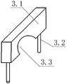
Fig. 2 is a schematic structural view of a clip member of the steel net cage lifting ball point integral rotating apparatus according to the present invention.
Fig. 3 is a structural view illustrating a support frame of the steel net frame jacking ball point integral rotating device according to the present invention.
Fig. 4 is a structural view illustrating a base of the steel net cage lifting ball point integral rotating device according to the present invention.
Fig. 5 is a process diagram of the lifting system according to the present invention when the spherical node with a low design elevation rises to its design elevation during the construction process.
Fig. 6 is a process diagram of the lifting system according to the present invention when the spherical node with a high design elevation rises to its design elevation during the construction process.
Fig. 7 is a schematic structural view of a fixed ball pivot device in the jacking system of the invention.
Reference numerals: 1 a base, 1.1 a bottom plate, 1.2 a riser, 1.3 a first draw-in groove, 1.4 a connection blind hole, 2 a support frame, 2.1 a support ring, 2.2 a bracing piece, 3 a hoop spare, 3.1 a hoop board, 3.2 a connecting rod, 3.3 a second draw-in groove, 4 a steel net rack, 5 a jacking pylon, 6 a major structure, 7 a spherical node, 8 a fixed ball fulcrum device, 8.1 a vertical steel plate support, 8.2 a horizontal connecting plate.
Detailed Description
As shown in fig. 1-4, the steel truss jacking ball point integral rotating device comprises a base 1, a support frame 2 arranged on the base 1 and a clamp member 3 clamped on the support frame 2; the base 1 comprises a horizontal bottom plate 1.1 and two vertical plates 1.2 which are connected to the bottom plate 1.1 in parallel at intervals; a vertical first clamping groove 1.3 is formed in the middle of the top of each vertical plate 1.2, and the first clamping grooves 1.3 on the two vertical plates 1.2 correspond to each other; connecting blind holes 1.4 are respectively formed in the top surface of the vertical plate 1.2 and on two sides of the first clamping groove 1.3; the supporting frame 2 is horizontally arranged at the top of the base 1, and two ends of the supporting frame 2 are respectively connected with the two vertical plates 1.2; the support frame 2 comprises a support ring 2.1 and a support rod 2.2 connected to the opposite side of the support ring 2.1; the supporting rod 2.2 is clamped in the first clamping groove 1.3 on the vertical plate 1.2 on the corresponding side and can rotate in the first clamping groove 1.3; the two clamp parts 3 are respectively connected to the tops of the two vertical plates 1.2 and clamped above the supporting rod 2.2; the clamp piece 3 comprises a vertical clamp plate 3.1 and connecting rods 3.2 connected to two sides of the bottom surface of the clamp plate 3.1; the distance between the connecting rods 3.2 is equal to the distance between the blind connecting holes 1.4 on the top surface of the vertical plate 1.2, and the connecting rods 3.2 are correspondingly inserted in the blind connecting holes 1.4; and a second clamping groove 3.3 corresponding to the first clamping groove 1.3 is also formed between the bottom surface of the clamp plate 3.1 and the connecting rods 3.2 positioned at the two sides.
In this embodiment, the first slot 1.3 is a semicircular slot, and the second slot 3.3 is a semicircular slot; the first clamping groove 1.3 and the second clamping groove 3.3 are spliced into a circular hoop, the supporting rod 2.2 is hooped in the circular hoop, and the supporting rod 2.2 is prevented from leaving the clamping grooves.
In this embodiment, the bottom plate 1.1 and the vertical plate 1.2 are both made of steel plates, and the bottom plate 1.1 and the vertical plate 1.2 are connected by welding (the welding seam is required to reach a first-level welding seam); the supporting ring 2.1 and the supporting rod 2.2 are both made of steel rod pieces, and the supporting ring 2.1 and the supporting rod 2.2 are connected in a welding mode; the hoop plate 3.1 is made of a steel plate, the connecting rod 3.2 is made of a steel rod piece, and the hoop plate 3.1 and the connecting rod 3.2 are connected through welding.
The jacking system comprises a steel net rack 4, a lifting device and a fixed ball pivot device; the steel net rack 4 is gradually inclined upwards from the edge to the middle, and the edge of the steel net rack is connected with the main body structure 6; the two lifting devices are correspondingly arranged below the two spherical nodes 7 of the steel net rack 4 along the inclined direction of the steel net rack 4; the steel net rack jacking ball point integral rotating device is arranged at the top of the lifting device close to one side of the edge of the steel net rack 4; the fixed ball pivot device is arranged at the top of the lifting device close to one side of the middle part of the steel net rack 4; the spherical joint 7 is respectively supported on the support frame 2 of the steel mesh frame jacking ball point integral rotating device and the top of the fixed ball pivot device.
In this embodiment, the lifting device includes a hydraulic jack and a lifting tower 5 fixedly connected to the top of the hydraulic jack; through holes are arranged on a bottom plate 1.1 of the steel mesh frame jacking ball point integral rotating device at intervals, and the steel mesh frame jacking ball point integral rotating device is connected with a jacking tower frame 5 through bolts penetrating through the through holes.
In the embodiment, the fixed ball pivot device comprises a vertical steel plate support 8.1 with a cross-shaped horizontal section and a horizontal connecting plate 8.2 connected to the bottom of the vertical steel plate support 8.1; the top edge of the vertical steel plate support 8.1 is gradually inclined downwards from the end part to the middle part to form a groove matched with the spherical node 7; the spherical joint close to one side of the middle part of the steel net rack 4 is detachably connected with the fixed ball pivot device.
In this embodiment, the diameter of the spherical node 7 is larger than the diameter of the supporting ring 2.1 on the supporting frame 2; the spherical joint close to one side of the edge of the steel net rack 4 is supported on the supporting ring 2.1 of the supporting frame 2 and can rotate on the supporting ring 2.1.
The construction method of the jacking system with the steel truss jacking ball point integral rotating device comprises the following steps.
Step one, manufacturing the steel truss jacking ball point integral rotating device, which comprises a base 1, a support frame 2 and a hoop component 3.
Step two, installing a lifting device; two lifting devices are arranged along the inclined direction of the steel net rack 4 to be installed, and the distance between the two lifting devices is equal to the distance between two adjacent spherical nodes 7 on the steel net rack 4 to be installed.
And step three, mounting a base 1 of the steel net rack jacking ball point integral rotating device at the top of the lifting device close to one side of the edge of the steel net rack 4, and mounting a fixed ball pivot device at the top of the lifting device close to one side of the middle part of the steel net rack 4.
Step four, horizontally installing the support frame 2 on the base 1, respectively clamping the support rods 2.2 at two sides of the support frame 2 in the first clamping grooves 1.3 on the vertical plates 1.2 at two sides of the base 1, and enabling the support rods 2.2 to be rotatable in the first clamping grooves 1.3.
And step five, clamping the clamp parts 3 on the support rods 2.2 at two sides of the support frame 2, and correspondingly inserting the connecting rods 3.2 at two sides of the bottom surface of the clamp parts 3 into the connecting blind holes 1.4 on the top surface of the vertical plate 1.2.
And step six, placing the steel net frame 4 to be installed on the top of the steel net frame jacking ball point integral rotating device and the top of the fixed ball pivot point device.
Step seven, jacking the two lifting devices simultaneously, and when the spherical node close to one side of the edge of the steel net rack 4 is lifted to the designed elevation, the lifting device below the spherical node is not jacked any more; continue the spherical node that the jacking is close to steel net rack 4 middle part one side, when the spherical node that is close to steel net rack 4 middle part one side rises to its design elevation, the rising device of its below is the jacking no longer, when only the jacking is close to the spherical node of steel net rack 4 middle part one side, the bracing piece 2.2 of steel net rack jacking ball point integral rotation device rotates in the draw-in groove that corresponds, plays variable angle pivoted effect.
And step eight, fixedly connecting the edge part of the steel net rack 4 with the main structure 6.
In this embodiment, the step two of installing the lifting device includes installing a jack and installing a jacking tower 5; in the third step, the base 1 of the steel net rack jacking ball point integral rotating device is connected on the jacking tower of the lifting device close to one side of the edge of the steel net rack 4 through bolts, and the horizontal connecting plate 8.2 at the bottom of the fixed ball fulcrum device is connected on the jacking tower of the lifting device close to one side of the middle part of the steel net rack 4 through bolts.
In this embodiment, the lower portions of two adjacent spherical joints 7 on the steel framework 4 in the step six are respectively embedded in the corresponding supporting ring 2.1 and the groove at the top of the fixed ball pivot device, and the spherical joints 7 can rotate relatively in the supporting ring 2.1 and the groove.
The embodiments described in this specification are merely illustrative of implementations of the inventive concept and the scope of the invention should not be considered limited to the specific forms set forth in the embodiments but encompasses equivalent technical means as would be appreciated by those skilled in the art based on the inventive concept.
Claims (7)
1. A jacking system containing a steel net rack jacking ball point integral rotating device comprises a steel net rack (4), a lifting device and a fixed ball pivot point device (8); the steel net rack (4) is gradually inclined upwards from the edge to the middle, and the edge of the steel net rack is connected with the main body structure (6); the method is characterized in that: the steel truss jacking ball point integral rotating device comprises a base (1), a support frame (2) arranged on the base (1) and a clamp member (3) clamped on the support frame (2); the base (1) comprises a horizontal bottom plate (1.1) and two vertical plates (1.2) which are connected to the bottom plate (1.1) in parallel at intervals; a vertical first clamping groove (1.3) is formed in the middle of the top of each vertical plate (1.2), and the first clamping grooves (1.3) on the two vertical plates (1.2) correspond to each other; connecting blind holes (1.4) are respectively formed in the top surface of the vertical plate (1.2) and positioned on two sides of the first clamping groove (1.3); the supporting frame (2) is horizontally arranged at the top of the base (1), and two ends of the supporting frame (2) are respectively connected with the two vertical plates (1.2); the support frame (2) comprises a support ring (2.1) and a support rod (2.2) connected to the opposite side of the support ring (2.1); the supporting rod (2.2) is clamped in a first clamping groove (1.3) on the vertical plate (1.2) on the corresponding side and can rotate in the first clamping groove (1.3); the two clamp parts (3) are respectively connected to the tops of the two vertical plates (1.2) and clamped above the supporting rod (2.2); the clamp piece (3) comprises a vertical clamp plate (3.1) and connecting rods (3.2) connected to two sides of the bottom surface of the clamp plate (3.1); the distance between the connecting rods (3.2) is equal to the distance between the connecting blind holes (1.4) on the top surface of the vertical plate (1.2), and the connecting rods (3.2) are correspondingly inserted in the connecting blind holes (1.4); a second clamping groove (3.3) corresponding to the first clamping groove (1.3) is also formed between the connecting rods (3.2) on the two sides of the bottom surface of the clamp plate (3.1); the two lifting devices are correspondingly arranged below two spherical nodes (7) of the steel net rack (4) along the inclined direction of the steel net rack (4); the steel net rack jacking ball point integral rotating device is arranged at the top of the lifting device close to one side of the edge of the steel net rack (4); the fixed ball pivot device (8) is arranged at the top of the lifting device close to one side of the middle part of the steel net rack (4); the spherical nodes (7) are respectively supported on a support frame (2) of the steel truss jacking ball point integral rotating device and a fixed ball pivot device (8); the lifting device comprises a hydraulic jack and a jacking tower frame (5) fixedly connected to the top of the hydraulic jack; through holes are arranged on a bottom plate (1.1) of the steel mesh frame jacking ball point integral rotating device at intervals, and the steel mesh frame jacking ball point integral rotating device is connected with a jacking tower frame (5) through bolts penetrating through the through holes; the fixed ball pivot device (8) comprises a vertical steel plate support (8.1) with a cross-shaped horizontal section and a horizontal connecting plate (8.2) connected to the bottom of the vertical steel plate support (8.1); the top edge of the vertical steel plate support (8.1) is gradually inclined downwards from the end part to the middle part to form a groove matched with the spherical joint (7); the spherical node close to one side of the middle part of the steel net rack (4) is detachably connected with the fixed ball fulcrum device (8).
2. The jacking system with the steel truss jacking ball point integral rotating device as claimed in claim 1, wherein: the first clamping groove (1.3) is a semicircular clamping groove, and the second clamping groove (3.3) is a semicircular clamping groove; the first clamping groove (1.3) and the second clamping groove (3.3) are spliced into a circular hoop, and the supporting rod (2.2) is hooped in the circular hoop.
3. The jacking system with the steel truss jacking ball point integral rotating device as claimed in claim 1, wherein: the bottom plate (1.1) and the vertical plate (1.2) are both made of steel plates, and the bottom plate (1.1) and the vertical plate (1.2) are connected in a welding manner; the supporting circular ring (2.1) and the supporting rod (2.2) are both made of steel rod pieces, and the supporting circular ring (2.1) and the supporting rod (2.2) are connected in a welding manner; the clamp plate (3.1) is made of a steel plate, the connecting rod (3.2) is made of a steel rod piece, and the clamp plate (3.1) is connected with the connecting rod (3.2) in a welding mode.
4. The jacking system with the steel truss jacking ball point integral rotating device as claimed in claim 1, wherein: the diameter of the spherical node (7) is larger than that of a supporting ring (2.1) on the supporting frame (2); the spherical joint close to one side of the edge of the steel net rack (4) is supported on a supporting ring (2.1) of the supporting frame (2) and can rotate on the supporting ring (2.1).
5. A construction method of a jacking system with a steel truss jacking ball point integral rotating device as claimed in any one of claims 1 and 4, comprising the steps of:
manufacturing a steel truss jacking ball point integral rotating device, wherein the steel truss jacking ball point integral rotating device comprises a base (1), a support frame (2) and a hoop piece (3);
step two, installing a lifting device; arranging two lifting devices along the inclined direction of a steel net rack (4) to be installed, wherein the distance between the two lifting devices is equal to the distance between two adjacent spherical nodes (7) on the steel net rack (4) to be installed;
step three, installing a base (1) of a steel net rack jacking ball point integral rotating device at the top of a lifting device close to one side of the edge of the steel net rack (4), and installing a fixed ball pivot point device (8) at the top of the lifting device close to one side of the middle part of the steel net rack (4);
step four, horizontally installing the support frame (2) on the base (1), respectively clamping the support rods (2.2) on two sides of the support frame (2) in first clamping grooves (1.3) on vertical plates (1.2) on two sides of the base (1), and enabling the support rods (2.2) to rotate in the first clamping grooves (1.3);
fifthly, clamping the clamp members (3) on the support rods (2.2) on the two sides of the support frame (2), and correspondingly inserting the connecting rods (3.2) on the two sides of the bottom surface of the clamp members (3) into the connecting blind holes (1.4) on the top surface of the vertical plate (1.2);
sixthly, placing the steel net rack (4) to be installed on the top of the steel net rack jacking ball point integral rotating device and the top of the fixed ball pivot point device (8);
step seven, jacking the two lifting devices simultaneously, and when the spherical node close to one side of the edge of the steel net rack (4) rises to the designed elevation, the lifting device below the spherical node is not jacked any more; continuously jacking the spherical node close to one side of the middle part of the steel net rack (4), and when the spherical node close to one side of the middle part of the steel net rack (4) rises to the designed elevation, the lifting device below the spherical node does not jack any more;
and step eight, fixedly connecting the edge part of the steel net rack (4) with the main structure (6).
6. The construction method of the jacking system with the steel truss jacking ball point integral rotating device as claimed in claim 5, wherein: the step two, installing the lifting device comprises installing a jack and installing a jacking tower frame (5); in the third step, the base (1) of the steel net rack jacking ball point integral rotating device is connected to the jacking tower frame of the lifting device close to one side of the edge of the steel net rack (4) through bolts, and the horizontal connecting plate (8.2) at the bottom of the fixed ball point device (8) is connected to the jacking tower frame of the lifting device close to one side of the middle of the steel net rack (4) through bolts.
7. The construction method of the jacking system with the steel truss jacking ball point integral rotating device as claimed in claim 5, wherein: and the lower parts of two adjacent spherical nodes (7) on the steel net rack (4) in the step six are respectively embedded in the corresponding supporting circular ring (2.1) and the groove at the top of the fixed ball fulcrum device (8), and the spherical nodes (7) can relatively rotate in the supporting circular ring (2.1) and the groove.
Priority Applications (1)
| Application Number | Priority Date | Filing Date | Title |
|---|---|---|---|
| CN201710300454.4A CN106906911B (en) | 2017-05-02 | 2017-05-02 | Steel truss jacking ball point integral rotating device, jacking system and construction method |
Applications Claiming Priority (1)
| Application Number | Priority Date | Filing Date | Title |
|---|---|---|---|
| CN201710300454.4A CN106906911B (en) | 2017-05-02 | 2017-05-02 | Steel truss jacking ball point integral rotating device, jacking system and construction method |
Publications (2)
| Publication Number | Publication Date |
|---|---|
| CN106906911A CN106906911A (en) | 2017-06-30 |
| CN106906911B true CN106906911B (en) | 2022-07-01 |
Family
ID=59210885
Family Applications (1)
| Application Number | Title | Priority Date | Filing Date |
|---|---|---|---|
| CN201710300454.4A Active CN106906911B (en) | 2017-05-02 | 2017-05-02 | Steel truss jacking ball point integral rotating device, jacking system and construction method |
Country Status (1)
| Country | Link |
|---|---|
| CN (1) | CN106906911B (en) |
Families Citing this family (3)
| Publication number | Priority date | Publication date | Assignee | Title |
|---|---|---|---|---|
| CN108571077A (en) * | 2018-05-18 | 2018-09-25 | 中国二十二冶集团有限公司 | Across the rotation axis assembly installation method of rack starting |
| CN111980165A (en) * | 2020-08-07 | 2020-11-24 | 中建八局第二建设有限公司 | Large-span net rack external-expanding splicing integral jacking construction method |
| CN118128183B (en) * | 2024-04-30 | 2024-08-20 | 山西四建集团有限公司 | Large-span reticulated shell structure and space vertical swivel mounting method |
Citations (6)
| Publication number | Priority date | Publication date | Assignee | Title |
|---|---|---|---|---|
| NL1001314C2 (en) * | 1995-09-29 | 1997-04-03 | Ballast Nedam Groep Nv | Method for erecting a building and building erected in this way. |
| CN201276564Y (en) * | 2008-06-11 | 2009-07-22 | 邹慈生 | Dumping methane fermentation device |
| CN101956426A (en) * | 2010-04-13 | 2011-01-26 | 天津大学 | Multi-hinge-line lifting-up spherical surface reticulated shell structure and construction method thereof |
| CN203879020U (en) * | 2014-04-15 | 2014-10-15 | 中国建筑第八工程局有限公司 | Net rack splicing moulding bed |
| CN204370833U (en) * | 2014-12-19 | 2015-06-03 | 山西四建集团有限公司 | Elements of Space Grid Truss supporting apparatus |
| CN206681155U (en) * | 2017-05-02 | 2017-11-28 | 中建城市建设发展有限公司 | A kind of Elements of Space Grid Truss jacking ball point Integral rotating device and jack-up system |
-
2017
- 2017-05-02 CN CN201710300454.4A patent/CN106906911B/en active Active
Patent Citations (6)
| Publication number | Priority date | Publication date | Assignee | Title |
|---|---|---|---|---|
| NL1001314C2 (en) * | 1995-09-29 | 1997-04-03 | Ballast Nedam Groep Nv | Method for erecting a building and building erected in this way. |
| CN201276564Y (en) * | 2008-06-11 | 2009-07-22 | 邹慈生 | Dumping methane fermentation device |
| CN101956426A (en) * | 2010-04-13 | 2011-01-26 | 天津大学 | Multi-hinge-line lifting-up spherical surface reticulated shell structure and construction method thereof |
| CN203879020U (en) * | 2014-04-15 | 2014-10-15 | 中国建筑第八工程局有限公司 | Net rack splicing moulding bed |
| CN204370833U (en) * | 2014-12-19 | 2015-06-03 | 山西四建集团有限公司 | Elements of Space Grid Truss supporting apparatus |
| CN206681155U (en) * | 2017-05-02 | 2017-11-28 | 中建城市建设发展有限公司 | A kind of Elements of Space Grid Truss jacking ball point Integral rotating device and jack-up system |
Also Published As
| Publication number | Publication date |
|---|---|
| CN106906911A (en) | 2017-06-30 |
Similar Documents
| Publication | Publication Date | Title |
|---|---|---|
| CN106906911B (en) | Steel truss jacking ball point integral rotating device, jacking system and construction method | |
| CN111424822A (en) | Support-free construction method for annular large cantilever cable bearing grid structure | |
| CN109826082B (en) | Construction method for installing decorative structure in multi-tower combined space of cable-stayed bridge | |
| CN205852606U (en) | Three dimensions tubular truss assembly moulding bed | |
| CN109440942B (en) | Installation structure and construction process of factory building roof grid | |
| CN206681155U (en) | A kind of Elements of Space Grid Truss jacking ball point Integral rotating device and jack-up system | |
| CN111716034B (en) | Assembling and welding method for spherical tank with large skirt support structure | |
| CN202817599U (en) | Jumper wire bracing frame | |
| CN104563476B (en) | A kind of large-size spherical tank interior construction device | |
| CN2509281Y (en) | Adjustable bearing structure for overhead floors | |
| CN110924682A (en) | Adjustable support system of precast beam component and use method thereof | |
| CN216239356U (en) | How word form high-speed railway station room steel space frame roofing | |
| CN111502027B (en) | Inverted cone jacking method for large-span grid structure | |
| CN215166585U (en) | Quick connecting device without beam arch | |
| KR101858539B1 (en) | Scaffold clamp for multiple support | |
| CN112609954B (en) | Novel automatic climbing system in elevator shaft and construction method thereof | |
| CN209838282U (en) | Connecting device between manual ladder stand and pier column | |
| CN212026316U (en) | Foundation bolt fixing device | |
| CN114150879A (en) | Adjustable supporting device for splicing large-scale complex steel structure nodes | |
| CN109296217B (en) | Reinforcement member of wood column and use method thereof | |
| CN203428849U (en) | Detachable hoisting support | |
| CN203223042U (en) | Novel space truss structure memorial archway | |
| CN115182597B (en) | Human-shaped double-inclined-span steel column butt joint construction method | |
| CN206538036U (en) | Tool-type adjustable hydraulic cable reel stent | |
| CN206971698U (en) | The jacking-up spacing structure of the automatic lifting system of Steel Structure Installation |
Legal Events
| Date | Code | Title | Description |
|---|---|---|---|
| PB01 | Publication | ||
| PB01 | Publication | ||
| SE01 | Entry into force of request for substantive examination | ||
| SE01 | Entry into force of request for substantive examination | ||
| GR01 | Patent grant | ||
| GR01 | Patent grant |