CN106848552B - Circularly polarized antenna array structure based on spatial phase compensation and phase compensation method - Google Patents
Circularly polarized antenna array structure based on spatial phase compensation and phase compensation method Download PDFInfo
- Publication number
- CN106848552B CN106848552B CN201611143610.2A CN201611143610A CN106848552B CN 106848552 B CN106848552 B CN 106848552B CN 201611143610 A CN201611143610 A CN 201611143610A CN 106848552 B CN106848552 B CN 106848552B
- Authority
- CN
- China
- Prior art keywords
- antenna
- phase compensation
- row
- subarrays
- circularly polarized
- Prior art date
- Legal status (The legal status is an assumption and is not a legal conclusion. Google has not performed a legal analysis and makes no representation as to the accuracy of the status listed.)
- Active
Links
- 238000000034 method Methods 0.000 title claims abstract description 20
- 230000010287 polarization Effects 0.000 claims description 6
- 230000003247 decreasing effect Effects 0.000 claims 2
- 230000006866 deterioration Effects 0.000 abstract description 6
- 238000003491 array Methods 0.000 description 13
- 238000010586 diagram Methods 0.000 description 3
- 230000006870 function Effects 0.000 description 3
- 230000015572 biosynthetic process Effects 0.000 description 2
- 230000007423 decrease Effects 0.000 description 2
- 230000000694 effects Effects 0.000 description 2
- 238000012545 processing Methods 0.000 description 2
- 238000004088 simulation Methods 0.000 description 2
- 238000004891 communication Methods 0.000 description 1
- 238000004590 computer program Methods 0.000 description 1
- 238000010276 construction Methods 0.000 description 1
- 238000013500 data storage Methods 0.000 description 1
- 238000013461 design Methods 0.000 description 1
- 238000001514 detection method Methods 0.000 description 1
- 238000006073 displacement reaction Methods 0.000 description 1
- 238000012986 modification Methods 0.000 description 1
- 230000004048 modification Effects 0.000 description 1
- 230000003287 optical effect Effects 0.000 description 1
- 230000000750 progressive effect Effects 0.000 description 1
Images


Classifications
-
- H—ELECTRICITY
- H01—ELECTRIC ELEMENTS
- H01Q—ANTENNAS, i.e. RADIO AERIALS
- H01Q1/00—Details of, or arrangements associated with, antennas
- H01Q1/36—Structural form of radiating elements, e.g. cone, spiral, umbrella; Particular materials used therewith
- H01Q1/38—Structural form of radiating elements, e.g. cone, spiral, umbrella; Particular materials used therewith formed by a conductive layer on an insulating support
-
- H—ELECTRICITY
- H01—ELECTRIC ELEMENTS
- H01Q—ANTENNAS, i.e. RADIO AERIALS
- H01Q1/00—Details of, or arrangements associated with, antennas
- H01Q1/50—Structural association of antennas with earthing switches, lead-in devices or lightning protectors
-
- H—ELECTRICITY
- H01—ELECTRIC ELEMENTS
- H01Q—ANTENNAS, i.e. RADIO AERIALS
- H01Q21/00—Antenna arrays or systems
- H01Q21/0006—Particular feeding systems
Landscapes
- Variable-Direction Aerials And Aerial Arrays (AREA)
Abstract
本发明提供基于空间相位补偿的圆极化天线阵结构及相位补偿方法,所述天线阵结构包括预设数量的天线单元,各个天线单元包括贴片以及设置于所述贴片中心的馈电点,所述贴片的两个对角按照预设切角尺寸进行切角,所述贴片中按照预设开槽尺寸开设U型槽位;旋转角度间隔为90°的4个天线单元构成一个子阵,各个子阵在水平方向和垂直方向分布,在垂直方向中,下一排子阵中的各个天线单元相比于上一排子阵的各个天线单元分别进行90°旋转,并且每个子阵的第二排首个天线单元采用45°相位补偿。本发明提供的基于空间相位补偿的圆极化天线阵结构及相位补偿方法,能够解决因大角度扫描导致轴比恶化影响天线阵性能的问题。
The present invention provides a circularly polarized antenna array structure and a phase compensation method based on spatial phase compensation. The antenna array structure includes a preset number of antenna elements, and each antenna element includes a patch and a feeding point disposed at the center of the patch. , the two diagonal corners of the patch are chamfered according to the preset chamfering size, and the U-shaped slot is opened according to the preset slotting size in the patch; four antenna units with a rotation angle interval of 90° form a Subarrays, each subarray is distributed in the horizontal direction and the vertical direction, in the vertical direction, each antenna element in the next row of subarrays is rotated by 90° compared to each antenna element in the previous row of subarrays, and each subarray is rotated by 90°. The first antenna element in the second row of the array adopts 45° phase compensation. The circularly polarized antenna array structure and phase compensation method based on spatial phase compensation provided by the present invention can solve the problem that the deterioration of the axial ratio caused by large-angle scanning affects the performance of the antenna array.
Description
技术领域technical field
本发明涉及圆极化天线阵列技术领域,具体涉及一种基于空间相位补偿的圆极化天线阵结构及相位补偿方法。The invention relates to the technical field of circularly polarized antenna arrays, in particular to a circularly polarized antenna array structure and a phase compensation method based on spatial phase compensation.
背景技术Background technique
相控阵天线是用电子方法实现天线波束指向在空间转动或扫描的天线,越来越广泛地运用在军事、民用各个方面。相控阵天线的天线单元结构多种多样,其中微带贴片天线单元因具有体积小、质量小、平面结构薄、能与载体共形、易于实现线极化和圆极化等优点而得到广泛应用,常用于构成相控阵天线的天线单元。Phased array antennas are antennas that use electronic methods to achieve antenna beam pointing in space to rotate or scan, and are more and more widely used in military and civilian applications. The antenna element structure of the phased array antenna is various, among which the microstrip patch antenna element has the advantages of small size, small mass, thin plane structure, conformal shape with the carrier, easy to realize linear polarization and circular polarization, etc. Widely used, it is often used to form the antenna unit of the phased array antenna.
由于圆极化天线能发射或接收线极化或圆极化电磁信号,而线极化天线不具备这样的特性,所以通信与侦测等应用领域常使用具有圆极化特性的相控阵天线。圆极化天线发射与接收的性能由多方面因素决定,其中圆极化天线的轴比是主要指标,通常情况下,扫描角度越大,轴比恶化越明显,因此在设计圆极化相控阵天线时,需要重点分析扫描角度较大时轴比是否能满足指标要求。Because circularly polarized antennas can transmit or receive linearly polarized or circularly polarized electromagnetic signals, while linearly polarized antennas do not have such characteristics, phased array antennas with circularly polarized characteristics are often used in applications such as communication and detection. . The transmit and receive performance of a circularly polarized antenna is determined by many factors, among which the axial ratio of the circularly polarized antenna is the main indicator. Usually, the larger the scanning angle, the more obvious the deterioration of the axial ratio. Therefore, in the design of circularly polarized phase control When the array antenna is used, it is necessary to focus on analyzing whether the axial ratio can meet the index requirements when the scanning angle is large.
研究发现,不同的二次圆极化排列方式会导致不同的圆极化效果,大扫描角度时,轴比差别较大,目前尚未出现能够较好改善圆极化天线性能的相控阵天线结构。The study found that different secondary circular polarization arrangements will lead to different circular polarization effects. When the scanning angle is large, the axial ratio is greatly different. At present, there is no phased array antenna structure that can better improve the performance of circularly polarized antennas. .
发明内容SUMMARY OF THE INVENTION
本发明实施例的目的在于提供一种基于空间相位补偿的圆极化天线阵结构及相位补偿方法,能够解决因大角度扫描导致轴比恶化影响天线阵性能的问题。The purpose of the embodiments of the present invention is to provide a circularly polarized antenna array structure and phase compensation method based on spatial phase compensation, which can solve the problem that the deterioration of the axial ratio caused by the large-angle scanning affects the performance of the antenna array.
为实现上述目的,本发明实施例一方面提供一种基于空间相位补偿的圆极化天线阵结构,包括预设数量的天线单元,各个天线单元包括贴片以及设置于所述贴片中心的馈电点,所述贴片的两个对角按照预设切角尺寸进行切角,所述贴片中按照预设开槽尺寸开设U型槽位;其中,旋转角度间隔为90°的4个天线单元构成一个子阵,各个子阵在水平方向和垂直方向分布,在垂直方向中,下一排子阵中的各个天线单元相比于上一排子阵的各个天线单元分别进行90°旋转,并且每个子阵的第二排首个天线单元采用45°相位补偿。In order to achieve the above object, one aspect of the embodiments of the present invention provides a circularly polarized antenna array structure based on spatial phase compensation, which includes a preset number of antenna elements, and each antenna element includes a patch and a feeder disposed at the center of the patch. Electric point, the two opposite corners of the patch are chamfered according to the preset chamfering size, and U-shaped slots are opened in the patch according to the preset slotting size; wherein, the rotation angle interval is 4 90° The antenna elements form a sub-array, and each sub-array is distributed in the horizontal and vertical directions. In the vertical direction, each antenna element in the next row of sub-arrays is rotated by 90° compared to each of the antenna elements in the previous row of sub-arrays. , and the first antenna element in the second row of each sub-array adopts 45° phase compensation.
进一步地,各个天线单元的馈电方式采用同轴馈电,并且所述预设数量的天线单元按照三角形栅格形式进行分布。Further, the feeding mode of each antenna unit adopts coaxial feeding, and the predetermined number of antenna units are distributed in the form of a triangular grid.
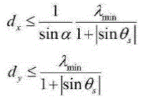
进一步地,按照下述公式确定天线单元之间的间距范围:Further, the distance range between the antenna elements is determined according to the following formula:


其中,dx表示相邻天线单元在水平方向的间距,dy表示相邻天线单元在垂直方向的间距,α为三角形栅格形式分布的腰与水平方向的夹角,θs为波束扫描角,λmin为天线带内最小工作波长。Among them, d x represents the spacing between adjacent antenna elements in the horizontal direction, dy represents the spacing between adjacent antenna elements in the vertical direction, α is the angle between the waist of the triangular grid and the horizontal direction, and θ s is the beam scanning angle , λ min is the minimum operating wavelength in the antenna band.
进一步地,按照下述公式确定天线单元的补偿相位值:Further, the compensation phase value of the antenna unit is determined according to the following formula:

其中,phase表示天线单元的补偿相位值,λ表示天线带的工作波长,φ表示天线阵列剖面角度。Among them, phase represents the compensation phase value of the antenna unit, λ represents the working wavelength of the antenna band, and φ represents the cross-sectional angle of the antenna array.
进一步地,当天线单元辐射左旋圆极化波时,在垂直方向中,下一排子阵中的各个天线单元相比于上一排子阵的各个天线单元分别进行顺时针旋转90°;当天线单元辐射右旋圆极化波时,下一排子阵中的各个天线单元相比于上一排子阵的各个天线单元分别进行逆时针旋转90°。Further, when the antenna unit radiates left-handed circularly polarized waves, in the vertical direction, each antenna unit in the next row of subarrays is rotated 90° clockwise compared to each antenna unit in the previous row of subarrays; when When the antenna elements radiate right-handed circularly polarized waves, each antenna element in the next row of sub-arrays is respectively rotated 90° counterclockwise compared to each of the antenna elements in the previous row of sub-arrays.
进一步地,当天线单元辐射左旋圆极化波时,在垂直方向中,旋转后的子阵第二排首个天线单元进行+45°的相位补偿;当天线单元辐射右旋圆极化波时,在垂直方向中,旋转后的子阵第二排首个天线单元进行-45°的相位补偿。Further, when the antenna unit radiates left-handed circularly polarized waves, in the vertical direction, the first antenna unit in the second row of the rotated sub-array performs +45° phase compensation; when the antenna unit radiates right-handed circularly polarized waves , in the vertical direction, the first antenna element in the second row of the rotated sub-array performs -45° phase compensation.
进一步地,当天线单元辐射左旋圆极化波时,在水平方向中,各个天线单元的旋转角度依次递减90°;当天线单元辐射右旋圆极化波时,在水平方向中,各个天线单元的旋转角度依次增加90°。Further, when the antenna unit radiates the left-handed circularly polarized wave, in the horizontal direction, the rotation angle of each antenna unit decreases by 90° in turn; when the antenna unit radiates the right-handed circularly polarized wave, in the horizontal direction, each antenna unit The rotation angle increases by 90° in turn.
为实现上述目的,本申请实施方式另一方面提供一种相位补偿方法,所述方法包括:将旋转角度间隔为90°的4个天线单元构成一个子阵,其中,各个子阵在水平方向和垂直方向分布;在垂直方向中,下一排子阵中的各个天线单元相比于上一排子阵的各个天线单元分别进行90°旋转,并且每个子阵的第二排首个天线单元采用45°相位补偿。In order to achieve the above object, embodiments of the present application provide, on the other hand, a phase compensation method, the method comprising: forming a sub-array with four antenna elements with a rotation angle interval of 90°, wherein each sub-array is in the horizontal direction and Distribution in the vertical direction; in the vertical direction, each antenna element in the next row of subarrays is rotated by 90° compared to each antenna element in the previous row of subarrays, and the first antenna element in the second row of each subarray adopts 45° phase compensation.
进一步地,各个天线单元的馈电方式采用同轴馈电,并且所述预设数量的天线单元按照三角形栅格形式进行分布。Further, the feeding mode of each antenna unit adopts coaxial feeding, and the predetermined number of antenna units are distributed in the form of a triangular grid.
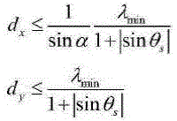
进一步地,按照下述公式确定天线单元之间的间距范围:Further, the distance range between the antenna elements is determined according to the following formula:
其中,dx表示相邻天线单元在水平方向的间距,dy表示相邻天线单元在垂直方向的间距,α为三角形栅格形式分布的腰与水平方向的夹角,θs为波束扫描角,λmin为天线带内最小工作波长。Among them, d x represents the spacing between adjacent antenna elements in the horizontal direction, dy represents the spacing between adjacent antenna elements in the vertical direction, α is the angle between the waist of the triangular grid and the horizontal direction, and θ s is the beam scanning angle , λ min is the minimum operating wavelength in the antenna band.
本申请实施方式提供的基于空间相位补偿的圆极化天线阵结构及相位补偿方法,使用中心馈电的圆极化天线单元,便于天线装配时单元旋转组阵和馈电;特有的空间相位补偿法是基于常规旋转组阵的基础,在水平方向和垂直方向分别进行有规律的相位补偿,以构成圆极化天线阵列,能够有效改善天线阵列的轴比参数,从而能够解决因大角度扫描以及轴比恶化影响天线阵性能的问题。进一步的,采用三角形栅格的布阵形式,可有效提高天线口径效率。The circularly polarized antenna array structure and phase compensation method based on spatial phase compensation provided by the embodiments of the present application use a centrally fed circularly polarized antenna unit, which is convenient for unit rotation, array formation and feeding during antenna assembly; unique spatial phase compensation The method is based on the basis of conventional rotating arrays, and regular phase compensation is carried out in the horizontal and vertical directions to form a circularly polarized antenna array, which can effectively improve the axial ratio parameters of the antenna array, so as to solve the problem of large-angle scanning and The deterioration of the axial ratio affects the performance of the antenna array. Further, using the triangular grid array form can effectively improve the antenna aperture efficiency.
附图说明Description of drawings
为了更清楚地说明本发明实施例中的技术方案,下面将对本发明实施例描述中所需要使用的附图作简单的介绍,显而易见地,下面描述中的附图仅仅是本发明的一些实施例,对于本领域普通技术人员来讲,在不付出创造性劳动的前提下,还可以根据本发明实施例的内容和这些附图获得其他的附图。In order to illustrate the technical solutions in the embodiments of the present invention more clearly, the following briefly introduces the accompanying drawings that need to be used in the description of the embodiments of the present invention. Obviously, the drawings in the following description are only some embodiments of the present invention. , for those of ordinary skill in the art, other drawings can also be obtained according to the contents of the embodiments of the present invention and these drawings without creative efforts.
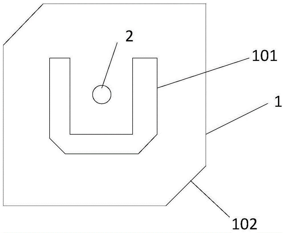
图1是本实施例所述的天线单元的结构示意图;FIG. 1 is a schematic structural diagram of the antenna unit according to this embodiment;
图2是本实施例中天线阵的各个天线单元的相位示意图;Fig. 2 is the phase schematic diagram of each antenna element of the antenna array in this embodiment;
图3是本实施例中天线阵的结构示意图;3 is a schematic structural diagram of an antenna array in this embodiment;
图4是本实施例所述的相位补偿方法流程图。FIG. 4 is a flowchart of the phase compensation method described in this embodiment.
贯穿附图,应该注意的是,相似的标号用于描绘相同或相似的元件、特征和结构。Throughout the drawings, it should be noted that like reference numerals are used to depict the same or similar elements, features and structures.
具体实施方式Detailed ways
提供以下参照附图的描述来帮助全面理解由权利要求及其等同物限定的本公开的各种实施例。以下描述包括帮助理解的各种具体细节,但是这些细节将被视为仅是示例性的。因此,本领域普通技术人员将认识到,在不脱离本公开的范围和精神的情况下,可对本文所述的各种实施例进行各种改变和修改。另外,为了清晰和简洁,公知功能和构造的描述可被省略。The following description with reference to the accompanying drawings is provided to assist in a comprehensive understanding of various embodiments of the present disclosure as defined by the claims and their equivalents. The following description includes various specific details to aid in that understanding, but these details are to be regarded as merely exemplary. Accordingly, those of ordinary skill in the art will recognize that various changes and modifications of the various embodiments described herein can be made without departing from the scope and spirit of the present disclosure. Also, descriptions of well-known functions and constructions may be omitted for clarity and conciseness.
以下描述和权利要求书中所使用的术语和词汇不限于文献含义,而是仅由发明人用来使本公开能够被清晰和一致地理解。因此,对于本领域技术人员而言应该明显的是,提供以下对本公开的各种实施例的描述仅是为了示例性目的,而非限制由所附权利要求及其等同物限定的本公开的目的。The terms and words used in the following description and claims are not limited to the bibliographical meanings, but, are merely used by the inventor to enable a clear and consistent understanding of the present disclosure. Accordingly, it should be apparent to those skilled in the art that the following description of various embodiments of the present disclosure is provided for illustrative purposes only and not for the purpose of limiting the present disclosure as defined by the appended claims and their equivalents .
应该理解,除非上下文明确另外指示,否则单数形式也包括复数指代。因此,例如,对“组件表面”的引用包括对一个或更多个这样的表面的引用。It should be understood that the singular forms also include the plural unless the context clearly dictates otherwise. Thus, for example, reference to "a component surface" includes reference to one or more of such surfaces.
本申请实施方式提供一种基于空间相位补偿的圆极化天线阵结构,所述天线阵结构中可以包括预设数量的天线单元。请参阅图1,各个天线单元包括贴片1以及设置于所述贴片中心的馈电点2,各个天线单元的馈电方式可以采用同轴馈电,所述贴片1的两个对角102按照预设切角尺寸进行切角,所述贴片1中按照预设开槽尺寸开设U型槽位101。其中,天线阵可以工作在Ka频段,调整贴片的各个尺寸可调节天线工作的频段。具体的,调节U型槽位101的开槽尺寸可有效调节阻抗匹配,调节对角102的切角尺寸可调整单元圆极化效果。Embodiments of the present application provide a circularly polarized antenna array structure based on spatial phase compensation, and the antenna array structure may include a preset number of antenna elements. Please refer to FIG. 1 , each antenna unit includes a
在本实施方式中,组阵建模之前,可以首先计算天线单元之间的初始间距和各个天线单元的相位值。为保证天线扫描范围内不出现栅瓣,天线单元的间距dx、dy需满足下式:In this embodiment, before forming the array modeling, the initial spacing between antenna elements and the phase value of each antenna element may be calculated first. In order to ensure that grating lobes do not appear in the scanning range of the antenna, the spacing d x and dy of the antenna elements must satisfy the following formulas:

其中,dx表示相邻天线单元在水平方向的间距,dy表示相邻天线单元在垂直方向的间距,α为三角形栅格形式分布的腰与水平方向的夹角,θs为波束扫描角,λmin为天线带内最小工作波长。根据公式计算初始值后,在水平方向可以取5.66mm作为水平间距,垂直方向可以取4.9mm作为垂直间距。天线阵列中,贴片的旋向需要与馈电相位保持一致,并且,在进行相位扫描时,每个单元都需要进行相位补偿,各个天线单元的补偿相位值由以下公式得到:Among them, d x represents the spacing between adjacent antenna elements in the horizontal direction, dy represents the spacing between adjacent antenna elements in the vertical direction, α is the angle between the waist of the triangular grid and the horizontal direction, and θ s is the beam scanning angle , λ min is the minimum operating wavelength in the antenna band. After calculating the initial value according to the formula, 5.66mm can be taken as the horizontal spacing in the horizontal direction, and 4.9mm can be taken as the vertical spacing in the vertical direction. In the antenna array, the rotation direction of the patch needs to be consistent with the feed phase, and during phase scanning, each element needs to perform phase compensation, and the compensation phase value of each antenna element is obtained by the following formula:

其中,phase表示天线单元的补偿相位值,λ表示天线带的工作波长,φ表示天线阵列剖面角度。Among them, phase represents the compensation phase value of the antenna unit, λ represents the working wavelength of the antenna band, and φ represents the cross-sectional angle of the antenna array.
在本实施方式中,64个天线单元可以构成8*8阵列。为改善相控阵微带天线轴比,等边三角形栅格形式组阵的单元数比方形栅格形式组阵的单元数节省13.3%,可有效提高天线口径效率,所以在本实施方式中为了节省单元与单元馈电系统,所述预设数量的天线单元在水平方向和垂直方向可以按照三角形栅格形式进行分布。In this embodiment, 64 antenna elements can form an 8*8 array. In order to improve the axial ratio of the phased array microstrip antenna, the number of elements in the equilateral triangle grid array is 13.3% less than that in the square grid array, which can effectively improve the antenna aperture efficiency. The unit and unit feeding system are saved, and the preset number of antenna units can be distributed in the form of a triangular grid in the horizontal direction and the vertical direction.
请参阅图2和图3,旋转角度间隔为90°的4个天线单元构成一个子阵,各个子阵在水平方向和垂直方向分布,在垂直方向中,下一排子阵中的各个天线单元相比于上一排子阵的各个天线单元分别进行90°旋转,并且每个子阵的第二排首个天线单元采用45°相位补偿。具体的,三角形栅格形式布阵与方形栅格形式布阵的区别在于第二排的单元发生了位移,所以需要进行相位补偿,补偿相位的大小可由位移距离计算得到,λ/4对应45°。在常规旋转组阵的基础上,可以给第二排首个阵元补偿45°相位角,所以第二排首个单元由90°变为135°。在垂直方向,下一个子阵由上一个子阵旋转90°得到,从而得到第三排和第四排单元,并且第四排首个单元的旋向和相位都需增加45°。在水平方向,按照天线单元间90°相位差的变化规律依次得到水平方向8个阵元,最终构成了8*8天线阵列,每个天线单元的初始相位如图2所示。Please refer to Figure 2 and Figure 3. Four antenna elements with a rotation angle interval of 90° form a sub-array, and each sub-array is distributed in the horizontal and vertical directions. In the vertical direction, each antenna element in the next row of sub-arrays Compared with the previous row of sub-arrays, each antenna element is rotated by 90°, and the first antenna element in the second row of each sub-array adopts 45° phase compensation. Specifically, the difference between the triangular grid array and the square grid array is that the cells in the second row are displaced, so phase compensation is required. The size of the compensation phase can be calculated from the displacement distance, and λ/4 corresponds to 45° . On the basis of the conventional rotating array, the first array element in the second row can be compensated for a 45° phase angle, so the first element in the second row is changed from 90° to 135°. In the vertical direction, the next sub-array is obtained by rotating the previous sub-array by 90°, thereby obtaining the third row and the fourth row of cells, and the rotation and phase of the first cell of the fourth row need to be increased by 45°. In the horizontal direction, 8 array elements in the horizontal direction are obtained in sequence according to the change law of the 90° phase difference between the antenna elements, and finally an 8*8 antenna array is formed. The initial phase of each antenna element is shown in Figure 2.
在本实施方式中,天线的初始相位需要和贴片旋向保持一致。本申请实施方式分析了天线阵列波束剖面角为0度,扫描角为60度时工作频带内高中低频点轴比的仿真结果,通过统计不同剖面不同扫描角度的仿真数据可知,当扫描角度在0°至60°范围内变化时,轴比值均小于3dB。本申请实施方式还分析了天线阵列波束剖面角为0°,扫描角为75°时高中低频点轴比的仿真结果,通过统计不同剖面不同扫描角度的仿真数据可知,当扫描角度在0°至75°范围内变化时,轴比值均小于5dB。结果表明,本申请实施方式中的天线阵结构与常规的组阵结构相比,能有效改善大角度扫描时轴比的恶化,使天线阵列辐射较好的圆极化波。In this embodiment, the initial phase of the antenna needs to be consistent with the patch rotation. The embodiment of the present application analyzes the simulation results of the axial ratio of the high, medium and low frequency points in the working frequency band when the beam profile angle of the antenna array is 0 degrees and the scanning angle is 60 degrees. When changing from ° to 60 °, the axial ratio is less than 3dB. The embodiment of the present application also analyzes the simulation results of the axial ratio of the high, medium and low frequency points when the beam profile angle of the antenna array is 0° and the scanning angle is 75°. When changing within the range of 75°, the axial ratio is less than 5dB. The results show that, compared with the conventional array structure, the antenna array structure in the embodiment of the present application can effectively improve the deterioration of the axial ratio during large-angle scanning, so that the antenna array can radiate better circularly polarized waves.
在本实施方式中,当天线单元辐射左旋圆极化波时,在垂直方向中,下一排子阵中的各个天线单元相比于上一排子阵的各个天线单元分别进行顺时针旋转90°;当天线单元辐射右旋圆极化波时,下一排子阵中的各个天线单元相比于上一排子阵的各个天线单元分别进行逆时针旋转90°。In this embodiment, when the antenna elements radiate left-handed circularly polarized waves, in the vertical direction, each antenna element in the next row of sub-arrays rotates 90 degrees clockwise compared to each antenna element in the previous row of sub-arrays. °; when the antenna unit radiates the right-handed circularly polarized wave, each antenna unit in the next row of sub-arrays is respectively rotated 90° counterclockwise compared to each of the antenna units in the previous row of sub-arrays.
此外,当天线单元辐射左旋圆极化波时,在垂直方向中,旋转后的子阵第二排首个天线单元进行+45°的相位补偿;当天线单元辐射右旋圆极化波时,在垂直方向中,旋转后的子阵第二排首个天线单元进行-45°的相位补偿。In addition, when the antenna unit radiates left-handed circularly polarized waves, in the vertical direction, the first antenna unit in the second row of the rotated sub-array performs +45° phase compensation; when the antenna unit radiates right-handed circularly polarized waves, In the vertical direction, the first antenna element in the second row of the rotated sub-array performs -45° phase compensation.
在本实施方式中,当天线单元辐射左旋圆极化波时,在水平方向中,各个天线单元的旋转角度依次递减90°;当天线单元辐射右旋圆极化波时,在水平方向中,各个天线单元的旋转角度依次增加90°。In this embodiment, when the antenna unit radiates the left-handed circularly polarized wave, in the horizontal direction, the rotation angle of each antenna unit decreases by 90° in turn; when the antenna unit radiates the right-handed circularly polarized wave, in the horizontal direction, The rotation angle of each antenna element is sequentially increased by 90°.
请参阅图4,本申请实施方式还提供一种相位补偿方法,所述方法包括以下步骤。Referring to FIG. 4 , an embodiment of the present application further provides a phase compensation method, and the method includes the following steps.
S1:将旋转角度间隔为90°的4个天线单元构成一个子阵,其中,各个子阵在水平方向和垂直方向分布;S1: 4 antenna units with a rotation angle interval of 90° form a sub-array, wherein each sub-array is distributed in the horizontal direction and the vertical direction;
S2:在垂直方向中,下一排子阵中的各个天线单元相比于上一排子阵的各个天线单元分别进行90°旋转,并且每个子阵的第二排首个天线单元采用45°相位补偿。S2: In the vertical direction, each antenna element in the next row of subarrays is rotated by 90° compared to each antenna element in the previous row of subarrays, and the first antenna element in the second row of each subarray adopts 45° Phase compensation.
在本实施方式中,各个天线单元的馈电方式采用同轴馈电,并且所述预设数量的天线单元按照三角形栅格形式进行分布。In this embodiment, the feeding mode of each antenna unit adopts coaxial feeding, and the predetermined number of antenna units are distributed in the form of a triangular grid.
在本实施方式中,按照下述公式确定天线单元之间的间距范围:In this embodiment, the distance range between the antenna elements is determined according to the following formula:

其中,dx表示相邻天线单元在水平方向的间距,dy表示相邻天线单元在垂直方向的间距,α为三角形栅格形式分布的腰与水平方向的夹角,θs为波束扫描角,λmin为天线带内最小工作波长。Among them, d x represents the spacing between adjacent antenna elements in the horizontal direction, dy represents the spacing between adjacent antenna elements in the vertical direction, α is the angle between the waist of the triangular grid and the horizontal direction, and θ s is the beam scanning angle , λ min is the minimum operating wavelength in the antenna band.
本申请实施方式提供的基于空间相位补偿的圆极化天线阵结构及相位补偿方法,使用中心馈电的圆极化天线单元,便于天线装配时单元旋转组阵和馈电;特有的空间相位补偿法是基于常规旋转组阵的基础,在水平方向和垂直方向分别进行有规律的相位补偿,以构成圆极化天线阵列,能够有效改善天线阵列的轴比参数,从而能够解决因大角度扫描以及轴比恶化影响天线阵性能的问题。进一步的,采用三角形栅格的布阵形式,可有效提高天线口径效率。The circularly polarized antenna array structure and phase compensation method based on spatial phase compensation provided by the embodiments of the present application use a centrally fed circularly polarized antenna unit, which is convenient for unit rotation, array formation and feeding during antenna assembly; unique spatial phase compensation The method is based on the basis of conventional rotating arrays, and regular phase compensation is carried out in the horizontal and vertical directions to form a circularly polarized antenna array, which can effectively improve the axial ratio parameters of the antenna array, so as to solve the problem of large-angle scanning and The deterioration of the axial ratio affects the performance of the antenna array. Further, using the triangular grid array form can effectively improve the antenna aperture efficiency.
应该注意的是,如上所述的本公开的各种实施例通常在一定程度上涉及输入数据的处理和输出数据的生成。此输入数据处理和输出数据生成可在硬件或者与硬件结合的软件中实现。例如,可在移动装置或者相似或相关的电路中采用特定电子组件以用于实现与如上所述本公开的各种实施例关联的功能。另选地,依据所存储的指令来操作的一个或更多个处理器可实现与如上所述本公开的各种实施例关联的功能。如果是这样,则这些指令可被存储在一个或更多个非暂时性处理器可读介质上,这是在本公开的范围内。处理器可读介质的示例包括只读存储器(ROM)、随机存取存储器(RAM)、CD-ROM、磁带、软盘和光学数据存储装置。另外,用于实现本公开的功能计算机程序、指令和指令段可由本公开所属领域的程序员容易地解释。It should be noted that the various embodiments of the present disclosure as described above generally involve the processing of input data and the generation of output data to some extent. This input data processing and output data generation can be implemented in hardware or software in combination with hardware. For example, certain electronic components may be employed in a mobile device or similar or related circuitry for implementing the functions associated with the various embodiments of the present disclosure as described above. Alternatively, one or more processors operating in accordance with stored instructions may implement the functions associated with the various embodiments of the present disclosure as described above. If so, it is within the scope of this disclosure that the instructions may be stored on one or more non-transitory processor-readable media. Examples of the processor-readable medium include read only memory (ROM), random access memory (RAM), CD-ROMs, magnetic tapes, floppy disks, and optical data storage devices. In addition, functional computer programs, instructions, and instruction segments for implementing the present disclosure can be easily construed by programmers skilled in the art to which the present disclosure pertains.
本说明书中的各个实施方式均采用递进的方式描述,各个实施方式之间相同相似的部分互相参见即可,每个实施方式重点说明的都是与其他实施方式的不同之处。Each embodiment in this specification is described in a progressive manner, and the same and similar parts between the various embodiments may be referred to each other, and each embodiment focuses on the differences from other embodiments.
尽管已参照本公开的各种实施例示出并描述了本公开,但是本领域技术人员将理解,在不脱离由所附权利要求及其等同物限定的本公开的精神和范围的情况下,可对其进行形式和细节上的各种改变。While the present disclosure has been shown and described with reference to various embodiments of the present disclosure, those skilled in the art will appreciate that, without departing from the spirit and scope of the present disclosure as defined by the appended claims and their equivalents Various changes in form and detail are made to it.
Claims (8)
Priority Applications (1)
| Application Number | Priority Date | Filing Date | Title |
|---|---|---|---|
| CN201611143610.2A CN106848552B (en) | 2016-12-13 | 2016-12-13 | Circularly polarized antenna array structure based on spatial phase compensation and phase compensation method |
Applications Claiming Priority (1)
| Application Number | Priority Date | Filing Date | Title |
|---|---|---|---|
| CN201611143610.2A CN106848552B (en) | 2016-12-13 | 2016-12-13 | Circularly polarized antenna array structure based on spatial phase compensation and phase compensation method |
Publications (2)
| Publication Number | Publication Date |
|---|---|
| CN106848552A CN106848552A (en) | 2017-06-13 |
| CN106848552B true CN106848552B (en) | 2020-02-07 |
Family
ID=59139779
Family Applications (1)
| Application Number | Title | Priority Date | Filing Date |
|---|---|---|---|
| CN201611143610.2A Active CN106848552B (en) | 2016-12-13 | 2016-12-13 | Circularly polarized antenna array structure based on spatial phase compensation and phase compensation method |
Country Status (1)
| Country | Link |
|---|---|
| CN (1) | CN106848552B (en) |
Families Citing this family (12)
| Publication number | Priority date | Publication date | Assignee | Title |
|---|---|---|---|---|
| CN109193182A (en) * | 2018-08-31 | 2019-01-11 | 北京乾中源科技有限公司 | A kind of circular conical surface conformal phased array antenna of 360 ° omni-directional scanning |
| CN109541324B (en) * | 2018-11-12 | 2020-09-25 | 北京航空航天大学 | A Method for Measuring Phase Center of Element Antennas in Array Based on Constricted Field |
| CN110086000A (en) * | 2019-05-15 | 2019-08-02 | 南京理工大学 | A kind of wide bandwidth scan angle phased array antenna |
| CN110233336B (en) * | 2019-05-20 | 2022-01-14 | 中国电子科技集团公司第三十八研究所 | Series-fed circularly polarized antenna normal array |
| CN112886280B (en) * | 2019-11-29 | 2022-06-07 | 华为技术有限公司 | Antenna system and communication equipment |
| US11641067B1 (en) | 2020-05-18 | 2023-05-02 | Amazon Technologies, Inc. | Passive antenna elements used to fill gaps in a paneltzed phased array antenna |
| US11664593B1 (en) | 2020-05-18 | 2023-05-30 | Amazon Technologies, Inc. | Antenna module with feed elements on a triangular lattice for antenna arrays |
| CN113517554B (en) * | 2021-08-11 | 2024-02-13 | 成都华芯天微科技有限公司 | Low-profile broadband dual-circularly polarized phased array antenna system |
| CN114583447B (en) * | 2022-04-01 | 2026-04-14 | 维沃移动通信有限公司 | Ultra-bandwidth antenna array and electronic equipment |
| CN115480316B (en) * | 2022-10-01 | 2025-01-17 | 北京卫星信息工程研究所 | An aeromagnetic compensation method for vector magnetic field sensor based on small signal model |
| CN115425412B (en) * | 2022-11-08 | 2023-03-24 | 成都华芯天微科技有限公司 | Phased array antenna with polarization mode adjusting function and phase configuration method |
| CN115986402B (en) * | 2022-12-22 | 2023-08-15 | 广州程星通信科技有限公司 | Circularly polarized phased array antenna |
Family Cites Families (6)
| Publication number | Priority date | Publication date | Assignee | Title |
|---|---|---|---|---|
| US4198640A (en) * | 1978-06-22 | 1980-04-15 | Rca Corporation | Reflectarray antenna |
| JP2000134024A (en) * | 1998-10-22 | 2000-05-12 | Mitsubishi Electric Corp | Array antenna device |
| CN103296341B (en) * | 2012-02-29 | 2019-02-01 | 深圳光启创新技术有限公司 | A kind of filter |
| CN103762423A (en) * | 2014-01-24 | 2014-04-30 | 中国科学院光电技术研究所 | Reflection array antenna beam scanning antenna based on rotary phase shift surface technology |
| CN105261838B (en) * | 2015-10-23 | 2018-08-07 | 中国科学院国家空间科学中心 | A kind of three frequency microstrip reflection array antenna of single layer |
| CN106099337B (en) * | 2016-01-12 | 2018-10-23 | 中国电子科技集团公司第十研究所 | Large-scale K-band conformal antenna front and preparation method thereof |
-
2016
- 2016-12-13 CN CN201611143610.2A patent/CN106848552B/en active Active
Also Published As
| Publication number | Publication date |
|---|---|
| CN106848552A (en) | 2017-06-13 |
Similar Documents
| Publication | Publication Date | Title |
|---|---|---|
| CN106848552A (en) | Circular polarization antenna array structure and phase compensating method based on space phase compensation | |
| CN113097735B (en) | Multifunctional super-surface and stealth antenna | |
| CN105226400B (en) | A broadband dual-polarized phased array antenna and full-polarization beamforming method | |
| CN112787098A (en) | Two-dimensional circularly polarized wide-angle scanning phased array antenna | |
| CN106911010B (en) | Large-unit-spacing phased array antenna based on subarray level | |
| CN102820542B (en) | Waveguide aperture antenna and wireless communication system | |
| CN108666743B (en) | Orthogonally polarized planar array antenna designed by cross-polarization suppression method | |
| CN107534215B (en) | Sparse Phase Mode Planar Feeding for Ring Arrays | |
| CN113594688B (en) | Circularly polarized antenna unit and antenna array | |
| CN113451782B (en) | Planar luneberg lens antenna with wide scanning angle | |
| CN103560336A (en) | Ku-band dual-band dual-polarized microstrip planar reflectarray antenna | |
| CN106096160A (en) | The axle of large-angle scanning rotational circle polarization micro-strip array antenna compares optimization method | |
| CN103219595A (en) | Circularly polarized antenna array having spinning characteristic in space structure | |
| CN105552538B (en) | A kind of two dimension wide-angle plane of scanning motion phased array antenna | |
| CN105261842A (en) | Microstrip reflective array unit loaded with cross slot on ground, and reflective array antenna | |
| CN110233336B (en) | Series-fed circularly polarized antenna normal array | |
| US9419347B2 (en) | Circularly polarized antenna | |
| CN116073132B (en) | Single-layer patch broadband low-profile double-circular polarization millimeter wave reflective array antenna | |
| US9614292B2 (en) | Circularly polarized antenna | |
| CN102176538A (en) | Multi-beam medium column lens antenna | |
| Chen et al. | An extremely compact multibeam folded transmitarray antenna based on reflectarray with additional phase compensation | |
| CN115832693A (en) | A Grating Lobe-less Patch Antenna Array with High Gain, Wide Angle Scanning and Large Element Spacing | |
| CN104882681A (en) | Circularly polarized antenna and manufacture method thereof | |
| Liao et al. | Broadband circular polarized reflectarray based on multi‐resonance unit | |
| CN108321551B (en) | Antenna array and antenna device |
Legal Events
| Date | Code | Title | Description |
|---|---|---|---|
| PB01 | Publication | ||
| PB01 | Publication | ||
| SE01 | Entry into force of request for substantive examination | ||
| SE01 | Entry into force of request for substantive examination | ||
| GR01 | Patent grant | ||
| GR01 | Patent grant |