CN106839552B - Ice maker assembly and refrigerator having the same - Google Patents
Ice maker assembly and refrigerator having the same Download PDFInfo
- Publication number
- CN106839552B CN106839552B CN201611101626.7A CN201611101626A CN106839552B CN 106839552 B CN106839552 B CN 106839552B CN 201611101626 A CN201611101626 A CN 201611101626A CN 106839552 B CN106839552 B CN 106839552B
- Authority
- CN
- China
- Prior art keywords
- guide
- water tank
- tray
- ice
- frame
- Prior art date
- Legal status (The legal status is an assumption and is not a legal conclusion. Google has not performed a legal analysis and makes no representation as to the accuracy of the status listed.)
- Active
Links
Images


Classifications
-
- F—MECHANICAL ENGINEERING; LIGHTING; HEATING; WEAPONS; BLASTING
- F25—REFRIGERATION OR COOLING; COMBINED HEATING AND REFRIGERATION SYSTEMS; HEAT PUMP SYSTEMS; MANUFACTURE OR STORAGE OF ICE; LIQUEFACTION SOLIDIFICATION OF GASES
- F25C—PRODUCING, WORKING OR HANDLING ICE
- F25C1/00—Producing ice
- F25C1/04—Producing ice by using stationary moulds
-
- F—MECHANICAL ENGINEERING; LIGHTING; HEATING; WEAPONS; BLASTING
- F25—REFRIGERATION OR COOLING; COMBINED HEATING AND REFRIGERATION SYSTEMS; HEAT PUMP SYSTEMS; MANUFACTURE OR STORAGE OF ICE; LIQUEFACTION SOLIDIFICATION OF GASES
- F25C—PRODUCING, WORKING OR HANDLING ICE
- F25C1/00—Producing ice
- F25C1/22—Construction of moulds; Filling devices for moulds
- F25C1/25—Filling devices for moulds
-
- F—MECHANICAL ENGINEERING; LIGHTING; HEATING; WEAPONS; BLASTING
- F25—REFRIGERATION OR COOLING; COMBINED HEATING AND REFRIGERATION SYSTEMS; HEAT PUMP SYSTEMS; MANUFACTURE OR STORAGE OF ICE; LIQUEFACTION SOLIDIFICATION OF GASES
- F25C—PRODUCING, WORKING OR HANDLING ICE
- F25C1/00—Producing ice
- F25C1/22—Construction of moulds; Filling devices for moulds
- F25C1/24—Construction of moulds; Filling devices for moulds for refrigerators, e.g. freezing trays
-
- F—MECHANICAL ENGINEERING; LIGHTING; HEATING; WEAPONS; BLASTING
- F25—REFRIGERATION OR COOLING; COMBINED HEATING AND REFRIGERATION SYSTEMS; HEAT PUMP SYSTEMS; MANUFACTURE OR STORAGE OF ICE; LIQUEFACTION SOLIDIFICATION OF GASES
- F25C—PRODUCING, WORKING OR HANDLING ICE
- F25C5/00—Working or handling ice
- F25C5/18—Storing ice
- F25C5/182—Ice bins therefor
-
- F—MECHANICAL ENGINEERING; LIGHTING; HEATING; WEAPONS; BLASTING
- F25—REFRIGERATION OR COOLING; COMBINED HEATING AND REFRIGERATION SYSTEMS; HEAT PUMP SYSTEMS; MANUFACTURE OR STORAGE OF ICE; LIQUEFACTION SOLIDIFICATION OF GASES
- F25D—REFRIGERATORS; COLD ROOMS; ICE-BOXES; COOLING OR FREEZING APPARATUS NOT OTHERWISE PROVIDED FOR
- F25D23/00—General constructional features
- F25D23/12—Arrangements of compartments additional to cooling compartments; Combinations of refrigerators with other equipment, e.g. stove
-
- F—MECHANICAL ENGINEERING; LIGHTING; HEATING; WEAPONS; BLASTING
- F25—REFRIGERATION OR COOLING; COMBINED HEATING AND REFRIGERATION SYSTEMS; HEAT PUMP SYSTEMS; MANUFACTURE OR STORAGE OF ICE; LIQUEFACTION SOLIDIFICATION OF GASES
- F25C—PRODUCING, WORKING OR HANDLING ICE
- F25C2400/00—Auxiliary features or devices for producing, working or handling ice
- F25C2400/06—Multiple ice moulds or trays therefor
-
- F—MECHANICAL ENGINEERING; LIGHTING; HEATING; WEAPONS; BLASTING
- F25—REFRIGERATION OR COOLING; COMBINED HEATING AND REFRIGERATION SYSTEMS; HEAT PUMP SYSTEMS; MANUFACTURE OR STORAGE OF ICE; LIQUEFACTION SOLIDIFICATION OF GASES
- F25C—PRODUCING, WORKING OR HANDLING ICE
- F25C2400/00—Auxiliary features or devices for producing, working or handling ice
- F25C2400/14—Water supply
-
- F—MECHANICAL ENGINEERING; LIGHTING; HEATING; WEAPONS; BLASTING
- F25—REFRIGERATION OR COOLING; COMBINED HEATING AND REFRIGERATION SYSTEMS; HEAT PUMP SYSTEMS; MANUFACTURE OR STORAGE OF ICE; LIQUEFACTION SOLIDIFICATION OF GASES
- F25D—REFRIGERATORS; COLD ROOMS; ICE-BOXES; COOLING OR FREEZING APPARATUS NOT OTHERWISE PROVIDED FOR
- F25D23/00—General constructional features
- F25D23/02—Doors; Covers
- F25D23/04—Doors; Covers with special compartments, e.g. butter conditioners
Landscapes
- Engineering & Computer Science (AREA)
- Physics & Mathematics (AREA)
- Mechanical Engineering (AREA)
- Thermal Sciences (AREA)
- General Engineering & Computer Science (AREA)
- Chemical & Material Sciences (AREA)
- Combustion & Propulsion (AREA)
- Devices That Are Associated With Refrigeration Equipment (AREA)
- Production, Working, Storing, Or Distribution Of Ice (AREA)
Abstract
本发明公开了可移动地设置在储存空间中的制冰机组件,并且提供了包含该制冰机组件的冰箱。制冰机组件设置在冰箱的储存空间中以形成冰,制冰机组件包括配置为形成冰的制冰单元和配置为储存在制冰单元中形成的冰的篮单元,其中制冰单元包括安装在冰箱处的框架、安装在框架处并具有形成冰的空间的托盘、可倾斜地安装在框架处并配置为向托盘供水的水箱,以及当水箱沿一个方向倾斜时,储存在水箱中的水被供应到托盘。

The present invention discloses an ice maker assembly movably disposed in a storage space, and provides a refrigerator including the ice maker assembly. The ice maker assembly is disposed in the storage space of the refrigerator to form ice, the ice maker assembly includes an ice making unit configured to form ice and a basket unit configured to store the ice formed in the ice making unit, wherein the ice making unit includes a mounting A frame at a refrigerator, a tray installed at the frame and having a space for forming ice, a water tank tiltably installed at the frame and configured to supply water to the tray, and water stored in the water tank when the water tank is inclined in one direction are supplied to trays.
Description
技术领域technical field
本公开涉及具有改进结构的制冰机组件和具有该制冰机组件的冰箱。The present disclosure relates to an ice maker assembly having an improved structure and a refrigerator having the ice maker assembly.
背景技术Background technique
通常,冰箱是将蒸发器中产生的冷气被供应到冷冻室和冷藏室以长时间保持各种食物的新鲜度的家用电器。应当保持在冷冻温度或更低温度的食物,例如肉、鱼、冷冻甜点等被储存在冷冻室中,而应当保持在高于冷冻温度的温度的食物,例如蔬菜、水果、饮料等被储存在冷藏室中。Generally, a refrigerator is a home appliance that supplies cold air generated in an evaporator to a freezing compartment and a refrigerating compartment to maintain the freshness of various foods for a long time. Foods that should be kept at or below freezing temperature, such as meat, fish, frozen desserts, etc., are stored in the freezer compartment, while food that should be kept at temperatures above freezing temperature, such as vegetables, fruits, beverages, etc., are stored in the freezer compartment. in the refrigerator.
能够形成冰的制冰机组件可以设置在冷冻室中。制冰机组件可以包括配置为接纳水的托盘,配置为将冰从托盘分离的取出装置,以及配置为储存从托盘分离的冰的冰篮。取出装置可以通过扭曲托盘来将冰从托盘分离。冰篮可以设置在托盘下方使得从托盘分离的冰可以落下并容纳在托盘中。An ice maker assembly capable of forming ice may be disposed in the freezer compartment. The ice maker assembly may include a tray configured to receive water, an extraction device configured to separate ice from the tray, and an ice basket configured to store ice separated from the tray. The extraction device can separate the ice from the tray by twisting the tray. An ice basket may be provided below the tray so that ice separated from the tray may fall and be contained in the tray.
常规地,制冰机组件安装在冷冻室内的搁板上。用户拆下托盘,直接向托盘供水,并将托盘安装在冷冻室内的搁板上。当供应到托盘的水被冻结并变成冰时,使用取出装置将冰从托盘分离,并且分离的冰被储存在设置在托盘下方的冰篮中。Conventionally, ice maker assemblies are mounted on shelves within the freezer compartment. The user removes the tray, supplies water directly to the tray, and installs the tray on a shelf in the freezer compartment. When the water supplied to the tray is frozen and becomes ice, the ice is separated from the tray using a take-out device, and the separated ice is stored in an ice basket provided under the tray.
当制冰机组件如上所述安装在冷冻室内的搁板上时,冷冻室内部的大量空间被制冰机组件占据,使得空间利用率低。此外,由于用户必须直接拆下托盘以向托盘供水,所以使用不方便。When the ice maker assembly is installed on the shelf in the freezing chamber as described above, a large amount of space inside the freezing chamber is occupied by the ice maker assembly, resulting in low space utilization. In addition, it is inconvenient to use since the user has to directly remove the tray to supply water to the tray.
发明内容SUMMARY OF THE INVENTION
为了解决上述缺点,主要目的是提供可移动地设置在储存空间中的制冰机组件,并且提供了具有该制冰机组件的冰箱。In order to solve the above disadvantages, the main purpose is to provide an ice maker assembly movably disposed in a storage space, and to provide a refrigerator having the ice maker assembly.
另外,根据实施方式,提供了可向托盘供水而不用拆下托盘的制冰机组件以及具有该制冰机组件的冰箱。In addition, according to an embodiment, there are provided an ice maker assembly capable of supplying water to a tray without removing the tray, and a refrigerator having the ice maker assembly.
另外,根据实施方式,提供了可拆卸地设置有水箱、托盘和冰篮的制冰机组件以及具有该制冰机组件的冰箱。In addition, according to an embodiment, there are provided an ice maker assembly detachably provided with a water tank, a tray and an ice basket, and a refrigerator having the ice maker assembly.
根据本公开的一个方面,制冰机组件设置在冰箱的储存空间中以形成冰,制冰机组件可包括配置为形成冰的制冰单元和配置为储存在制冰单元中形成的冰的篮单元,其中制冰单元可包括安装在冰箱处的框架、安装在框架处并具有形成冰的空间的托盘、可倾斜地安装在框架处并配置为向托盘供水的水箱,并且当水箱沿一个方向倾斜时,储存在水箱中的水被供应到托盘。According to an aspect of the present disclosure, an ice maker assembly is disposed in a storage space of a refrigerator to form ice, and the ice maker assembly may include an ice making unit configured to form ice and a basket configured to store the ice formed in the ice making unit unit, wherein the ice making unit may include a frame mounted at the refrigerator, a tray mounted at the frame and having a space for forming ice, a water tank tiltably mounted at the frame and configured to supply water to the tray, and when the water tank is in one direction When tilted, the water stored in the tank is supplied to the tray.
水箱可设置成可从框架拆卸。The water tank may be arranged to be removable from the frame.
水箱可设置成能够关于与水箱一体形成的旋转突起倾斜。The water tank may be provided so as to be able to be tilted with respect to a rotating protrusion integrally formed with the water tank.
配置为引导水箱的倾斜移动的引导突起可设置在水箱的侧表面处,并且配置为引导引导突起移动的安装引导件设置在框架处。A guide protrusion configured to guide the oblique movement of the water tank may be provided at a side surface of the water tank, and a mounting guide configured to guide the movement of the guide protrusion may be provided at the frame.
安装引导件可以包括第一容纳部和第二容纳部,第一容纳部配置为使得引导突起可移动地插入其中,第二容纳部配置为使得旋转突起设置在水箱的插入第二容纳部中的侧表面处,并且当旋转突起在第二容纳部中旋转时,引导突起沿着第一容纳部移动。The mounting guide may include a first accommodating portion configured such that the guide protrusion is movably inserted therein, and a second accommodating portion configured such that the rotating protrusion is disposed in the second accommodating portion of the water tank inserted into the second accommodating portion. At the side surface, and when the rotating protrusion is rotated in the second receiving portion, the guide protrusion moves along the first receiving portion.
第一容纳部的一侧和第二容纳部的一侧可以打开,以使容纳在第一容纳部中的引导突起和容纳在第二容纳部中的旋转突起能够分别离开第一容纳部和第二容纳部。One side of the first accommodating part and one side of the second accommodating part may be opened so that the guide protrusion accommodated in the first accommodating part and the rotating protrusion accommodated in the second accommodating part can be separated from the first accommodating part and the second accommodating part, respectively. Second accommodation.
第一容纳部可以包括锁定部分,锁定部分配置为当水箱沿一个方向倾斜并打开时抵触引导突起,以保持水箱沿这个方向倾斜。The first receiving portion may include a locking portion configured to interfere with the guide protrusion when the water tank is inclined and opened in one direction to keep the water tank inclined in this direction.
第一容纳部可以包括底座引导件,底座引导件配置为当水箱沿另一方向倾斜并关闭时抵触引导突起以防止水箱自由打开。The first receiving portion may include a base guide configured to abut against the guide protrusion to prevent the water tank from opening freely when the water tank is tilted and closed in the other direction.
底座引导件可以由底座部分的向上凸起形成的一部分来提供,引导突起能够在底座引导件上移动。The base guide may be provided by a portion formed by an upward protrusion of the base portion, the guide protrusion being able to move on the base guide.
框架可以包括连接到托盘并且配置为可倾斜的控制杆,并且当控制杆倾斜时托盘可以关于旋转轴旋转。The frame may include a lever connected to the tray and configured to be tiltable, and the tray may rotate about the axis of rotation when the lever is tilted.
篮单元可包括框架和可拆卸地设置在框架处的篮,并且篮可倾斜地安装在框架处。The basket unit may include a frame and a basket detachably provided at the frame, and the basket may be obliquely installed at the frame.
引导突起可以从篮的侧表面突出,并且框架可以包括安装引导件,安装引导件配置为通过将引导突起插入安装引导件中来引导引导突起。The guide protrusion may protrude from the side surface of the basket, and the frame may include a mounting guide configured to guide the guide protrusion by inserting the guide protrusion into the mounting guide.
安装引导件的一侧可以是开口的以使引导突起能够离开安装引导件。One side of the mounting guide may be open to enable the guide protrusion to exit the mounting guide.
安装引导件可以包括抵触突起,引导突起可以包括锁定部分,锁定部分配置为使得抵触突起插入锁定部分中,并且当篮安装在框架处并且沿一个方向倾斜时,抵触突起可以插入锁定部分中以保持篮倾斜。The mounting guide may include an interference protrusion, the guide protrusion may include a locking portion, the locking portion is configured such that the interference protrusion is inserted into the locking portion, and when the basket is mounted at the frame and inclined in one direction, the interference protrusion may be inserted into the locking portion to hold Basket tilted.
当篮沿另一方向倾斜时,抵触突起的一侧可以抵触设置在安装引导件处的旋转限制器,从而固定篮以防止篮沿一个方向移动。When the basket is tilted in the other direction, one side of the abutting protrusion may interfere with a rotation limiter provided at the mounting guide, thereby securing the basket to prevent the basket from moving in one direction.
根据本公开的一个方面,冰箱可以包括:主体,主体配置为在其中形成储存空间;门,门安装在主体处以打开和关闭储存空间;制冰单元,制冰单元可拆卸地安装在门处并配置为形成冰;以及篮单元,篮单元可拆卸地安装在门处并配置为储存在制冰单元中形成的冰。其中制冰单元包括具有形成冰的空间的托盘和倾斜以向托盘供水的水箱。According to an aspect of the present disclosure, a refrigerator may include: a main body configured to form a storage space therein; a door installed at the main body to open and close the storage space; an ice making unit detachably installed at the door and configured to form ice; and a basket unit detachably mounted at the door and configured to store ice formed in the ice making unit. Wherein the ice making unit includes a tray having a space for forming ice and a water tank inclined to supply water to the tray.
多个安装突起可以设置在门的内表面处,多个安装突起可以在竖直方向上彼此间隔,并且配置为抵触安装突起的抵触件可以设置在制冰单元的侧表面和篮单元的侧表面处。A plurality of mounting protrusions may be provided at the inner surface of the door, the plurality of mounting protrusions may be vertically spaced from each other, and an interference member configured to interfere with the mounting protrusions may be provided at a side surface of the ice making unit and a side surface of the basket unit place.
制冰单元和篮单元在门处的安装位置在竖直方向上是可变的。The installation positions of the ice making unit and the basket unit at the door are vertically variable.
制冰单元可以包括可拆卸地安装在门处的框架,并且水箱和托盘可以可倾斜地安装在框架处。The ice making unit may include a frame detachably mounted at the door, and the water tank and the tray may be tiltably mounted at the frame.
框架可以包括配置为容纳从水箱供应的水的容纳部,可以在容纳部的底表面处形成用于排出水的孔,并且底表面可以倾斜以使得引入到容纳部中的水流向孔。The frame may include an accommodating portion configured to accommodate water supplied from the water tank, a hole for draining water may be formed at a bottom surface of the accommodating portion, and the bottom surface may be inclined so that water introduced into the accommodating portion flows toward the hole.
在进行以下具体实施方式之前,阐述贯穿本专利文件使用的某些词语和短语的定义可能是有利的:术语“包括(include)”和“包含(comprise)”及其衍生词意味着非限制性的包括;术语“或(or)”是包括性的,意思是和/或;短语“与...相关联(associate with)”和“与此相关联(associate therewith)”及其衍生词可以意味着包括、被包括在内、与…互连、包含、被包含在内、连接到或与...连接、联接到或与...联接、可与…相通、配合、交织、并置、接近、绑定到或与...绑定、具有、具有属性等;并且术语“控制器(controller)”是指控制至少一个操作的任何装置、系统或其一部分,这样的装置可以以硬件、固件或软件或者硬件、固件或软件的至少两种的某种组合来实现。应当注意与任何特定控制器相关联的功能可以是集中式或分布式的,无论是本地还是远程。在整个本专利文件中提供了某些词语和短语的定义,本领域普通技术人员应当理解,在许多情况下(即使不是大多数情况),这样的定义适用于这样定义的词语和短语的先前以及将来的使用。Before proceeding to the following detailed description, it may be beneficial to set forth definitions of certain words and phrases used throughout this patent document: The terms "include" and "comprise" and their derivatives are meant to be non-limiting includes; the term "or" is inclusive, meaning and/or; the phrases "associate with" and "associate therewith" and derivatives thereof may means to include, be included in, interconnect with, contain, be contained in, be connected to or be connected with, be coupled to or be coupled with, be in communication with, mate with, interweave, juxtapose with , near, bound to or with, has, has attributes, etc.; and the term "controller" refers to any device, system, or portion thereof, that controls at least one operation, such a device may be in hardware , firmware or software, or some combination of at least two of hardware, firmware or software. It should be noted that the functionality associated with any particular controller may be centralized or distributed, whether locally or remotely. Definitions for certain words and phrases are provided throughout this patent document, those of ordinary skill in the art should understand that in many, if not most instances, such definitions apply to previous and future use.
附图说明Description of drawings
为了更完整地理解本公开及其有益效果,现在参考结合附图的以下描述,其中相同的附图标记表示相同的部分:For a more complete understanding of the present disclosure and its benefits, reference is now made to the following description taken in conjunction with the accompanying drawings, wherein like reference numerals refer to like parts:
图1示出了根据本公开的各种实施方式的冰箱的正视图;1 illustrates a front view of a refrigerator according to various embodiments of the present disclosure;
图2示出了根据本公开的各种实施方式的冰箱的内部的视图;2 shows a view of the interior of a refrigerator according to various embodiments of the present disclosure;
图3A和图3B示出了根据本公开的各种实施方式的制冰机组件安装在冰箱的门上的状态的视图;3A and 3B are views illustrating a state in which an ice maker assembly is mounted on a door of a refrigerator according to various embodiments of the present disclosure;
图4示出了根据本公开的各种实施方式的制冰单元的视图;4 shows a view of an ice making unit according to various embodiments of the present disclosure;
图5示出了根据本公开的各种实施方式的制冰单元的分解立体图;5 shows an exploded perspective view of an ice making unit according to various embodiments of the present disclosure;
图6示出了根据本公开的各种实施方式的制冰单元的一部分的视图;6 shows a view of a portion of an ice making unit according to various embodiments of the present disclosure;
图7示出了根据本公开的各种实施方式的制冰单元的横向截面图;7 illustrates a transverse cross-sectional view of an ice making unit according to various embodiments of the present disclosure;
图8示出了根据本公开的各种实施方式的制冰单元的安装引导件的视图;8 illustrates a view of an installation guide of an ice making unit according to various embodiments of the present disclosure;
图9示出了根据本公开的各种实施方式的安装在制冰单元处的水箱的视图;9 illustrates a view of a water tank installed at an ice making unit according to various embodiments of the present disclosure;
图10和图11示出了根据本公开的各种实施方式的水箱的引导突起被安装引导件引导的状态的视图;10 and 11 are views showing a state in which the guide protrusion of the water tank is guided by the installation guide according to various embodiments of the present disclosure;
图12示出了根据本公开的各种实施方式的制冰单元的控制杆倾斜的状态的视图;12 is a view showing a state in which a lever of the ice making unit is inclined according to various embodiments of the present disclosure;
图13示出了根据本公开的各种实施方式的控制杆和托盘之间的连接件的视图;13 shows a view of a connection between a lever and a tray according to various embodiments of the present disclosure;
图14示出了根据本公开的各种实施方式的托盘的一部分的视图;14 shows a view of a portion of a tray according to various embodiments of the present disclosure;
图15示出了根据本公开的各种实施方式的托盘旋转的状态的视图;15 is a view showing a state in which a tray is rotated according to various embodiments of the present disclosure;
图16示出了根据本公开的各种实施方式的篮单元的视图。16 shows a view of a basket unit according to various embodiments of the present disclosure.
图17示出了根据本公开的各种实施方式的篮单元的分解立体图。17 shows an exploded perspective view of a basket unit according to various embodiments of the present disclosure.
图18示出了根据本公开的各种实施方式的篮倾斜的状态的视图;18 is a view showing a state in which the basket is tilted according to various embodiments of the present disclosure;
图19示出了根据本公开的各种实施方式的篮和框架的侧视图;Figure 19 shows a side view of a basket and frame according to various embodiments of the present disclosure;
图20示出了根据本公开的各种实施方式的设置在篮单元的框架处的引导件的视图;20 shows a view of a guide provided at the frame of the basket unit according to various embodiments of the present disclosure;
图21示出了根据本公开的各种实施方式的设置在篮处的倾斜引导件的视图;21 shows a view of a tilt guide provided at a basket according to various embodiments of the present disclosure;
图22和图23示出了根据本公开的各种实施方式的倾斜引导件被引导件引导的状态的视图;22 and 23 are views illustrating a state in which the inclined guide is guided by the guide according to various embodiments of the present disclosure;
图24示出了根据本公开的各种实施方式的篮单元的视图;Figure 24 shows a view of a basket unit according to various embodiments of the present disclosure;
图25示出了根据本公开的各种实施方式的制冰机组件的视图。25 shows a view of an ice maker assembly according to various embodiments of the present disclosure.
图26示出了根据本公开的各种实施方式的托盘在制冰机组件中旋转的状态的视图;26 is a view showing a state in which the tray is rotated in the ice maker assembly according to various embodiments of the present disclosure;
图27示出了根据本公开的各种实施方式的篮单元的视图。27 shows a view of a basket unit according to various embodiments of the present disclosure.
图28示出了根据本公开的各种实施方式的设置在制冰单元中的水箱的视图;28 shows a view of a water tank provided in an ice making unit according to various embodiments of the present disclosure;
图29示出了根据本公开的各种实施方式的设置在制冰单元中的框架的一部分的视图;以及Figure 29 shows a view of a portion of a frame disposed in an ice making unit according to various embodiments of the present disclosure; and
图30示出了根据本公开的各种实施方式的制冰单元的一部分的视图。30 shows a view of a portion of an ice making unit according to various embodiments of the present disclosure.
具体实施方式Detailed ways
下文讨论的图1至图30以及用于在本专利文件中描述本公开的原理的各种实施方式仅仅是说明性的,而不应以任何方式解释为限制本公开的范围。本领域技术人员将理解,本公开的原理可以在任何适当布置的装置中实现。1 through 30, discussed below, and the various embodiments used to describe the principles of the present disclosure in this patent document are by way of illustration only and should not be construed in any way to limit the scope of the disclosure. Those skilled in the art will understand that the principles of the present disclosure may be implemented in any suitably arranged device.
在下文中,将参照附图详细描述根据实施方式的制冰机组件和具有该制冰机组件的冰箱。Hereinafter, an ice maker assembly and a refrigerator having the same according to an embodiment will be described in detail with reference to the accompanying drawings.
图1示出了根据本公开的各种实施方式的冰箱的正视图;图2示出了根据本公开的各种实施方式的冰箱的内部的视图。1 illustrates a front view of a refrigerator according to various embodiments of the present disclosure; and FIG. 2 illustrates a view of an interior of the refrigerator according to various embodiments of the present disclosure.
参考图1和图2,根据实施方式的冰箱1可以包括食物储存空间、具有在至少一侧形成的开口的主体10以及配置为打开和关闭开口的门11、门12、门13和门14。门11、门12、门13和门14可以分别包括配置为便于打开和关闭门11、门12、门13和门14的把手111、把手121、把手131和把手141。门11、门12、门13和门14可以是设置成可绕折叶旋转的旋转门。门11、门12、门13和门14中的一个或多个可以是连接到配置为储存食物的篮的抽屉式门。在下文中,将描述门11、门12、门13和门14是旋转门的实施方式。1 and 2 , the refrigerator 1 according to the embodiment may include a food storage space, a
隔板15可以横向地设置在主体10内部。主体10的内部空间可以由隔板15分成冷藏室和冷冻室。例如,由隔板15提供的上储存空间110和上储存空间120可以是冷藏室,并且下部储存空间130和下部储存空间140可以是冷冻室。The
在下文中,将描述上储存空间110和上储存空间120被设置为冷藏室并且下储存空间130和下储存空间140被设置为冷冻室的实施方式。Hereinafter, an embodiment in which the
上储存空间110和上储存空间120可以分别由第一门11和第二门12打开和关闭。上储存空间110和上储存空间120可以包括由第一门11打开和关闭的第一上储存空间110和由第二门12打开和关闭的第二上储存空间120。第一上储存空间110和第二上储存空间120可以设置为单个集成空间。The
上储存空间110和上储存空间120的一部分可以通过侧壁113被分为第一上储存空间110和第二上储存空间120。使用侧壁113以及上储存空间110和上储存空间120的内表面,可以容易地安装搁板112和搁板122。搁板112和搁板122可以设置为可移动的。篮115和篮125可以可抽拉地设置在上储存空间110和上储存空间120中。The
配置为储存食物的篮114和篮124可以分别安装在第一门11和第二门12的内表面处。可以设置多个篮114和篮124,并且篮114和篮124可以根据用户的方便而设置为可移动的。
下储存空间130和下储存空间140可以包括由隔板16分隔开的第一下储存空间130和第二下储存空间140。第一下储存空间130可以由第三门13打开和关闭,并且第二下储存空间140可以由第四门14打开和关闭。The
搁板132和搁板142可以分别设置在第一下储存空间130和第二下储存空间140以在其上放置食物。篮133和篮143可以分别设置在第一下储存空间130和第二下储存空间140中以在其中储存食物。
配置为储存食物的篮134和篮144可以分别安装在第三门13和第四门14的内表面。可以设置多个篮134和篮144,并且篮134和篮144可以根据用户的方便而设置为可移动的。
制冰机组件2可以安装在第三门13和第四门14中的至少一个的内表面。例如,制冰机组件2可以安装在第四门14的内表面。类似于安装在第四门14的内表面的篮144,制冰机组件2可以根据用户的方便而设置为可移动的。The
在下文中,将描述制冰机组件2安装在第四门14处的实施方式。Hereinafter, an embodiment in which the
图3A和图3B示出了根据本公开的各种实施方式的制冰机组件安装在冰箱的门上的状态的视图。3A and 3B are views illustrating a state in which the ice maker assembly according to various embodiments of the present disclosure is mounted on a door of a refrigerator.
参考图3A和图3B,根据本公开的各种实施方式,制冰机组件2可以安装在冰箱的第四门14处。制冰机组件2可以包括制冰单元3和篮单元4。冰可以形成在制冰单元3中。制冰单元3中形成的冰可以储存在篮单元4中。篮单元4可以设置在制冰单元3的下方。Referring to FIGS. 3A and 3B , according to various embodiments of the present disclosure, the
多个安装突起145可以从第四门14的内表面突出。多个安装突起145可以设置为在竖直方向上间隔开预定距离。A plurality of mounting
制冰机组件2可以通过设置在制冰机组件2的侧表面并且抵触安装突起145的抵触件317和402(参见图4和图16)安装在第四门14的内表面处。抵触件还可以设置在安装在第四门14处的篮144的侧表面,并且抵触件还可以设置为抵触安装突起145。The
用户可以通过释放制冰机组件2的抵触件317和抵触件402与安装突起145之间的抵触而将制冰机组件2从第四门14拆下。用户可以拆下制冰机组件2以将制冰机组件2安装在设置在第四门14上部的安装突起145上,或安装在设置在第四门14下部的安装突起145上。通过这种方式,用户可以方便地改变制冰机组件2的安装位置。这里,篮单元4可以设置在制冰单元3的下方,使得由制冰单元3形成的冰可以落下并储存在篮单元4中。The user can remove the
图4示出了根据本公开的各种实施方式的制冰单元的视图,并且图5示出了根据本公开的各种实施方式的制冰单元的分解立体图。4 shows a view of an ice making unit according to various embodiments of the present disclosure, and FIG. 5 shows an exploded perspective view of the ice making unit according to various embodiments of the present disclosure.
参考图4和图5,根据实施方式的制冰单元3可以包括配置为接纳水以形成冰的托盘30、配置为安装托盘30的框架31和框架32,以及配置为向托盘30供水的水箱33。4 and 5 , the
框架31和框架32可以包括安装在第四门14处的第一框架31和安装在第一框架31前面的第二框架32。托盘30可以安装在第一框架31处。水箱33可以可倾斜地安装在第二框架32处。托盘30和水箱33可以分别可拆卸地安装在第一框架31和第二框架32处。The
控制杆34可进一步设置在第一框架31和第二框架32中的任一个处。例如,控制杆34可安装在第二框架32处。控制杆34可通过连接件35连接到托盘30。控制杆34可倾斜地设置,并且用户可以倾斜控制杆34以将冰从托盘30分离。从托盘30分离的冰可落下并储存在设置在制冰单元3下方的篮单元4中。The
配置为抵触第四门14的安装突起145的抵触件317可以从第一框架31的一侧突出。制冰单元3可以通过抵触安装突起145的抵触件317安装在第四门14处。用户可以通过释放抵触件317与安装突起145之间的抵触而将制冰单元3从第四门14拆下。The
可以在第一框架31处设置容纳部310,容纳部310是引入水箱33的水的空间。水可以供应到水箱33,并且当水箱33倾斜时,容纳在水箱33中的水可以被引入到容纳部310中。A receiving
孔312可以形成在形成容纳部310的第一框架31的底表面311处。供应到容纳部310的水可以通过孔312排出并供应到托盘30。供应到容纳部310的水可以通过孔312排出并且被引入到设置在容纳部310下方的托盘30中。A
第一框架31的底表面311可以形成为倾斜的。孔312可以形成在底表面311的最低部分处。供应到容纳部310的水可以由倾斜的底表面311引导以通过孔312排出。The
可以在底表面311下方提供配置为容纳托盘30的托盘容纳空间。配置为使得托盘30可旋转地安装在其上的安装件314可以设置在形成托盘容纳空间的第一框架31的侧表面。布置在托盘30的一侧的旋转轴301a可以安装在安装件314处。安装件314可以以孔或槽的形式提供使得布置在托盘30的一侧的旋转轴301a可旋转地插入其中。设置在托盘30的另一侧的旋转轴301可以安装在连接到控制杆34的连接件35处。A tray accommodating space configured to accommodate the
止动器315可以设置在第一框架31的侧表面处以抵触设置在托盘30的一侧的抵触突起302。止动器315可以被台阶化以抵触托盘30的一侧以防止托盘30的一侧旋转预定的角度或更大角度。A
配置为使得紧固构件穿过其中的紧固件316可以设置在第一框架31处使得第二框架32安装到其上。
第一开口320可以形成在第二框架32的前部以使得水箱33能够被安装并且水箱33中的水能够被供应到容纳部310。配置为引导引导突起332以使水箱33能够倾斜的安装引导件323可以设置在形成第一开口320的第二框架32的侧表面。下文将描述安装引导件323的详细配置。水箱33可以可倾斜地安装在第二框架32处并且可以设置为在需要时可从第二框架32拆卸。The
控制杆34可以安装在第二框架32的一侧。配置为容纳控制杆34的控制杆容纳部321可以设置在第二框架32处以使控制杆34和第二框架32的前表面形成相同的平坦表面。The
配置为使得托盘30能够插入和取出的第二开口322可以设置在第二框架32处。第二开口322可以设置在第一开口320的下方。A
水箱33可以可倾斜地安装在第二框架32处。设置为可旋转并插入安装引导件323(安装引导件323设置在第二框架32处)的一侧的旋转突起333以及由安装引导件323引导的引导突起332可以包括在水箱33的侧表面处。通过沿着安装引导件323移动的引导突起332,水箱33可以稳定地倾斜。旋转突起333和安装引导件323可以与水箱33一体地注塑成型。The
水箱33可以可拆卸地安装在第二框架32上。因此,用户可以根据需要将水箱33从第二框架32拆下。例如,当需要清洁水箱33时,可以将水箱33从制冰单元3拆下以进行清洁。The
把手331可以设置在水箱33的一侧以使得用户能够在握住把手331的同时容易地倾斜水箱33。A
可以在托盘30中设置制冰部300,制冰部300是容纳水并形成冰的空间。旋转轴301a和旋转轴301可以设置在托盘30的侧表面。旋转轴301a和旋转轴301可以从托盘30的侧表面突出。An
设置在托盘30的一个侧表面处的旋转轴301a可以可旋转地安装在第一框架31的安装件314处。设置在托盘30的另一侧表面处的旋转轴301可以连接到控制杆34。旋转轴301可以通过连接件35连接到控制杆34。将在下文描述控制杆34和连接件35的详细配置。A
配置为抵触止动器315的抵触突起302可以从托盘30的侧表面突出。抵触突起302可以仅形成在托盘30的一个侧表面处。控制杆34可以连接到设置在托盘30的另一侧表面处的旋转轴301,并且当用户倾斜控制杆34时,托盘30可以旋转。在托盘30旋转预定角度之后,托盘30的一侧的旋转被抵触止动器315的抵触突起302限制。然而,托盘30的另一侧由于控制杆34的原因可以比托盘的一侧旋转更多并且使托盘30被扭曲。托盘30被扭曲,并且容纳在制冰部300中的冰可以从制冰部300分离。从托盘30分离的冰可以落下并且容纳在设置在托盘30下方的篮单元4中。The
同时,托盘30的旋转轴301a和301以及抵触突起302可以与托盘30一体地注塑成型。Meanwhile, the
设置在托盘30的另一侧的旋转轴301可以通过连接件35连接到控制杆34。用户可以倾斜控制杆34以使托盘30绕旋转轴301旋转。The
连接件35可以包括壳体350和壳体351以及设置在壳体350和壳体351中的齿轮352和齿轮353。齿轮352和齿轮353可以包括连接到控制杆34的第一齿轮352和连接到托盘30的旋转轴301的第二齿轮353。第二齿轮353可以与第一齿轮352啮合。The
当控制杆34倾斜时,第一齿轮352可与控制杆34一起旋转。当第一齿轮352沿一个方向旋转时,第二齿轮353可沿另一方向旋转。当第二齿轮353旋转时,安装在第二齿轮353处的托盘30可与第二齿轮353一起旋转。When the
设置在托盘30的另一侧表面处的旋转轴301可以插入到设置在第二齿轮353处的旋转轴插入孔353a中。设置在托盘30的一个侧表面处的旋转轴301a可以可拆卸地安装在设置在第一框架31处的安装件314处,并且设置在托盘30的另一侧表面处的旋转轴301可以可拆卸地安装在旋转轴插入孔353a处。The
用户可以根据需要从制冰单元3拆下托盘30。例如,当托盘30需要清洁时,用户可以容易地从制冰单元3拆下托盘30以清洁托盘30。用户可以从制冰单元3拆下托盘30并通过形成在第二框架32处的第二开口322取出托盘30直至第二框架32的前部。The user can detach the
如上所述,水箱33和托盘30可拆卸地安装在制冰单元3处以使得制冰单元3可以被卫生地管理。As described above, the
盖36可以安装在形成在第二框架32处的第二开口322处。盖36设置成打开和关闭第二开口322。例如,盖36可以设置为可绕折叶轴360倾斜。用户可以打开盖36以将托盘30安装在第一框架31处,或者通过第二开口322将托盘30从第一框架31拆下。The
图6示出了根据各种实施方式的制冰单元的一部分的视图,图7示出了根据各种实施方式的制冰单元的横向截面图。6 shows a view of a portion of an ice making unit according to various embodiments, and FIG. 7 shows a transverse cross-sectional view of the ice making unit according to various embodiments.
参考图6和图7,根据各种实施方式,设置在制冰单元3处的水箱33可以倾斜。用户可以使用水箱33向托盘30供水。水箱33可以设置为绕旋转突起333倾斜。Referring to FIGS. 6 and 7 , according to various embodiments, the
形成在第一框架31处的容纳部310可以由水箱33常闭。当需要向托盘30供水时,用户可以倾斜水箱33以打开容纳部310。The
在水箱33上可以存在指示线(未示出),使得足够量的水可以供应到托盘30。用户可以沿一个方向A供水直到达到水箱33的指示线。There may be an indicator line (not shown) on the
在将足够量的水供应到水箱33之后,水箱33可以沿另一方向B倾斜。当水箱33沿另一方向B倾斜时,水箱33中的水可以被引入到容纳部310中并且通过形成在底表面311处的孔312排出。通过孔312排出的水可以被供应到托盘30。After a sufficient amount of water is supplied to the
通过这种方式,用户可以使用设置在制冰单元3处的水箱33容易地向托盘30供应足够量的水。In this way, the user can easily supply a sufficient amount of water to the
图8示出了根据各种实施方式的制冰单元的安装引导件的视图,图9示出了根据各种实施方式的安装在制冰单元处的水箱的视图,并且图10和图11示出了根据各种实施方式的水箱的引导突起被安装引导件引导的状态的视图。8 shows a view of an installation guide of an ice making unit according to various embodiments, FIG. 9 shows a view of a water tank installed at the ice making unit according to various embodiments, and FIGS. 10 and 11 show A view is shown of a state in which the guide protrusion of the water tank is guided by the installation guide according to various embodiments.
参考图8至图11,根据各种实施方式,水箱33可以可倾斜且可拆卸地安装在第二框架32处。设置在水箱33处的旋转突起333可以可旋转地安装在第二框架32处,并且第二框架32可以包括配置为引导引导突起332的移动的安装引导件323。通过沿着安装引导件323移动的引导突起332,水箱33可以稳定地倾斜。Referring to FIGS. 8 to 11 , according to various embodiments, the
安装引导件323可以以弯曲肋的形式设置。安装引导件323可以包括配置为使得引导突起332可移动地插入其中的第一容纳部324和配置为使得旋转突起333插入其中的第二容纳部325。The mounting guides 323 may be provided in the form of curved ribs. The mounting
第一容纳部324和第二容纳部325中的每一个可以具有一个开口侧。引导突起332和旋转突起333可以通过开口的一侧进入和离开第一容纳部324和第二容纳部325。通过这种方式,水箱33可以可拆卸地安装在第二框架32处。Each of the first receiving
插入到第二容纳部325中的旋转突起333可以设置成在相同位置旋转而不线性移动。第一容纳部324可以形成为与当水箱33绕旋转突起333旋转时的引导突起332的移动路径对应。也就是说,第一容纳部324可以设置成具有长于第二容纳部325的路径。The
同时,第一容纳部324和第二容纳部325可以通过弯曲单个完整的肋形成。Meanwhile, the first receiving
当在安装引导件323处可移动地插入到第一容纳部324中的引导突起332所在的部分被称为底座引导件327时,向下凹陷弯曲的第一底座部分326可以设置在底座引导件327的靠近第一容纳部324的入口328处的位置。设置在第一底座部分326处的底座引导件327可以抵触设置在入口328附近的锁定部分326a并且防止其自由离开第一容纳部324。When the portion where the
当水箱33沿一个方向A倾斜并打开时,引导突起332可以设置在第一底座部分326处并且可以抵触锁定部分326a,使得水箱33可以保持倾斜。When the
当水箱33沿另一方向B倾斜并关闭时,引导突起332可以设置在第二底座部分329处,第二底座部分329设置在第一容纳部324的内部。第二底座部分329可以通过向下凹陷地弯曲底座引导件327形成。也就是说,当水箱33沿另一方向B倾斜时,引导突起332可以沿着底座引导件327移动,并且当引导突起332设置在第二底座部分329时,可以通过直接在第二底座部分329前面向上凸起形成的底座引导件327a防止引导突起332自由地离开第二底座部分329。When the
因为如上所述防止引导突起332自由离开第一底座部分326,所以只要没有向其施加外力,水箱33就可以在打开的同时保持连接到第二框架32。因为引导突起332被防止离开第二底座部分329,所以只要没有向其施加外力,水箱33就可以保持关闭。Because the
因此,由于不需要除了水箱33和第二框架32之外的附加部分来实现水箱33的可倾斜结构,因此可以节省用于生产附加部分的制造成本。此外,由于可以省略用于组装附加部分的过程,因此可以提高生产效率。Therefore, since additional parts other than the
此外,因为水箱33可倾斜地设置在制冰单元3处,所以可以容易地向托盘30供应足够量的水,而不需要连接附加元件或者拆下托盘30以向托盘30供水。Furthermore, since the
此外,由于水箱33可拆卸地设置在第二框架32处,所以水箱33在从第二框架32拆下之后可以容易地清洁。因此,水箱33可以被卫生地管理。Furthermore, since the
图12示出了根据各种实施方式的制冰单元的控制杆倾斜的状态的视图,图13示出了根据各种实施方式的控制杆和托盘之间的连接件的视图,图14示出了根据各种实施方式的托盘的一部分的视图,并且图15示出了根据各种实施方式的托盘旋转的状态的视图。12 is a view showing a state in which a lever of the ice making unit is tilted according to various embodiments, FIG. 13 is a view showing a connection between the lever and a tray according to various embodiments, and FIG. 14 is a diagram showing A view of a part of the tray according to various embodiments is shown, and FIG. 15 shows a view of a state in which the tray is rotated according to various embodiments.
参考图12至图15,根据各种实施方式的制冰单元3可以包括连接到托盘30以旋转托盘30的控制杆34。控制杆34可以可倾斜地安装在第二框架32处。用户可沿一个方向倾斜杆34以将冰从托盘30分离。当控制杆34沿一个方向倾斜时,托盘30可旋转。托盘30旋转预定角度然后被扭曲,从而使托盘30中的冰能够从托盘30分离。Referring to FIGS. 12 to 15 , the
旋转轴301a和与旋转轴301a间隔开预定距离的抵触突起302可以设置在托盘30的一个侧表面30a处。当托盘30旋转预定角度时,抵触突起302可以抵触设置在第一框架31的内表面处的止动器315。A
旋转轴301可以设置在托盘30的另一侧表面30b处。设置在托盘30的另一侧表面30b处的旋转轴301可以通过齿轮连接到控制杆34。控制杆34可以连接到第一齿轮352,并且旋转轴301可以连接到与第一齿轮352啮合的第二齿轮353。当控制杆34倾斜时,托盘30可以由通过第一齿轮352、第二齿轮353和旋转轴301向托盘30传递的旋转力而旋转。The
尽管上文已经描述了控制杆34和托盘30通过齿轮连接的实施方式,但是控制杆34和托盘30的连接结构不限于上述的连接结构。Although the embodiment in which the
当控制杆34沿一个方向倾斜时,托盘30可以沿另一个方向倾斜。当托盘30沿另一方向旋转预定角度时,设置在托盘30的一个侧表面处的抵触突起302可以抵触止动器315。当抵触突起302抵触止动器315时,托盘30的一侧可以停止旋转,并且当控制杆34沿一个方向进一步倾斜时,托盘30的另一侧可以沿另一方向进一步旋转。由于托盘30的一侧和另一侧的旋转角度不同,所以托盘30的形状可能被扭曲,并且容纳在托盘30中的冰可以从托盘30分离。When the
通过分别从安装件314和第二齿轮353拆下旋转轴301a和旋转轴301,可以将托盘30从第一框架31拆下。用户可以在需要清洁托盘30时容易地将托盘30从第一框架31拆下并且卫生地管理托盘30。The
从托盘30分离的冰可以落下并容纳在设置在制冰单元3下方的篮单元4中。在下文中,将参照附图详细描述篮单元4的结构。The ice separated from the
图16示出了根据各种实施方式的篮单元的视图,图17示出了根据各种实施方式的篮单元的分解立体图,图18示出根据各种实施方式的篮倾斜的状态的视图,并且图19示出了根据各种实施方式的篮和框架的侧视图。16 shows a view of a basket unit according to various embodiments, FIG. 17 shows an exploded perspective view of the basket unit according to various embodiments, FIG. 18 shows a view of a state in which the basket is inclined according to various embodiments, And FIG. 19 shows a side view of a basket and frame according to various embodiments.
参考图16至图19,根据各种实施方式的篮单元4可以包括安装在第四门14处的框架40和安装在框架40处的篮41。篮41可以包括储存件410,储存件410是配置为容纳制冰单元3中形成的冰的空间。篮41可以安装在框架40处并倾斜。用户可以倾斜篮41以取出储存在篮41内的冰。Referring to FIGS. 16 to 19 , the
框架40可以可拆卸地安装在第四门14处。考虑到第二下储存空间140(参见图2)的空间利用率,用户可以改变篮单元4的位置。也就是说,用户可以将篮单元4放置在第四门14的上部或下部。The
在竖直方向上间隔开预定距离的多个安装突起145可以设置在第四门14的内表面处。可以抵触安装突起145的抵触件402可以设置在框架40的一个或多个侧表面处。抵触件402可以从框架40的侧表面突出。用户可以使抵触件402抵触安装突起145,以将框架40安装在第四门14的内表面。此外,用户可以释放抵触件402和安装突起145之间的抵触以将框架40从第四门14的内表面拆下。A plurality of mounting
框架40可以设置为围绕篮41的外表面的一部分。例如,框架40可以设置为围绕篮41的后表面、侧表面的至少一部分以及底表面的至少一部分。框架40可包括容纳部400,容纳部400配置为容纳篮41的后表面、侧表面的至少一部分以及底表面的至少一部分。由于篮41被容纳在容纳部400中,篮41可以被框架40稳定地支撑并且固定到第四门14的内表面。The
篮41可以可拆卸地安装在框架40处。此外,篮41被设置为在安装在框架40处时可倾斜。引导突起411可以形成在篮41处,并且配置为通过将引导突起411插入其中来引导引导突起411的安装引导件401可以设置在框架40处。安装引导件401可以与篮41一体地注塑成型。引导突起411可以与框架40一体地设置。The
在下文中,将描述篮41和框架40可倾斜地联接的结构。Hereinafter, a structure in which the
图20示出了根据各种实施方式的设置在篮单元的框架处的引导件的视图,图21示出了根据各种实施方式的设置在篮处的倾斜引导件的视图,并且图22和图23示出了根据各种实施方式的倾斜引导件被引导件引导的状态的视图。FIG. 20 shows a view of a guide provided at the frame of the basket unit according to various embodiments, FIG. 21 shows a view of an inclined guide provided at the basket according to various embodiments, and FIGS. 22 and 21 FIG. 23 is a view showing a state in which the inclined guide is guided by the guide according to various embodiments.
参考图20至图23,根据各种实施方式,引导突起411可以从篮41突出,并且配置为通过将引导突起411插入其中来引导引导突起411的安装引导件401可以设置在框架40处。20 to 23 , according to various embodiments, guide
安装引导件401的入口407可以被设置为打开,引导突起411通过入口407进入和离开安装引导件401。由于安装引导件401的入口407被设置为打开,所以引导突起411可以容易地插入安装引导件401中或离开安装引导件401。此外,篮41可以可拆卸地安装在框架40处。The
篮41可以在倾斜的同时安装在框架40处,并且可以在倾斜的同时从框架40拆下。The
引导突起411可以包括设置在相对于基本上直线延伸的连接件415的一端的第一引导件413和设置在另一端的第二引导件414。第一引导件413和第二引导件414的直径D1可以形成为大于连接件415的宽度D2。The
锁定部分416可以凹陷地形成在第一引导件413附近。The locking
安装引导件401可以包括配置为容纳第一引导件413的第一引导件容纳部403和配置为容纳第二引导件414的第二引导件容纳部404。The mounting
当篮41在倾斜的同时安装在框架40处时,第二引导件414可以设置在第二引导件容纳部404中。连接件413可以安置于设置在安装引导件401的下部的直线部分405上。When the
安装引导件401可以包括配置为插入到锁定部分416中的抵触突起408。抵触突起408可以朝向安装引导件401的内部突出。The mounting
抵触突起408可以在篮41倾斜的同时插入锁定部分416中。由于锁定部分416如上所述来抵触该抵触突起408,因此篮41可以保持倾斜预定角度,并且引导突起411可以不容易离开安装引导件401。The
当沿一个方向倾斜的篮41沿另一个方向倾斜时,安装引导件401可以关于第二引导件414在另一个方向上旋转,并且第一引导件413可以设置在第一引导件容纳部403中。第一引导件413可以在沿着另一个方向旋转的同时穿过向下凸出地形成的旋转限制器406。旋转限制器406可以形成为向下凸出以具有低于第一引导件容纳部403的高度。旋转限制器406可以设置为具有张力,使得第一引导件403可以通过外力容易地穿过旋转限制器406。When the
当第一引导件413设置在第一引导件容纳部403中时,第一引导件413可以抵触旋转限制器406,并且只要没有向其施加外力,第一引导件413就保持设置在第一引导件容纳部403中。通过这种方式,当篮41关闭时,只要没有向其施加外力就可以防止篮41自由地打开。When the
如上所述,用户可以通过倾斜篮41容易地取出冰。由于不需要除了篮41和框架40之外的附加元件就可以使篮41能够倾斜地设置,因此可以节省用于生产附加元件的制造成本。此外,由于可以省略用于组装附加需要的部分的过程,因此可以提高生产效率。As described above, the user can easily take out the ice by tilting the
此外,由于篮41可拆卸地设置在框架40处,因此用户可以根据需要容易地将篮41从框架40拆下以清洁篮41。因此,篮41可以被卫生地管理。In addition, since the
图24示出根据各种实施方式的篮单元的视图。24 shows a view of a basket unit according to various embodiments.
参考图24,根据另一实施方式的篮单元5可以包括框架50和篮51。篮51可以可抽拉地设置为抽屉。篮51可以包括储存件510,储存件510是配置为容纳制冰单元3中形成的冰的空间。图24所示的制冰单元可以与图4至图15所示的制冰单元相同。Referring to FIG. 24 , the
框架50可以包括配置为容纳篮51的容纳部500。配置为抵触从冰箱门突出的安装突起的抵触件可以设置在框架50的外表面处。框架50可以通过抵触安装突起的抵触件而安装在冰箱门处。The
配置为引导篮51的移动的轨道501可以设置在框架50的内表面处。轨道501可以设置为从框架50的前部朝向其后部延伸。配置为沿着轨道501移动的滑块511可以设置在篮51的外表面处。在篮51的外表面处可设置有滚柱,以使滑块511能够沿着轨道501平滑地滑动。A
图25示出了根据各种实施方式的制冰机组件的视图,图26示出了根据各种实施方式的托盘在制冰机组件中旋转的状态的视图,并且图27示出了根据各种实施方式的篮单元的视图。25 shows a view of the ice maker assembly according to various embodiments, FIG. 26 shows a view of a state in which the tray is rotated in the ice maker assembly according to various embodiments, and FIG. 27 shows a view according to various embodiments. A view of an embodiment of the basket unit.
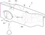
参考图25至图27,根据各种实施方式,制冰机组件6可以包括配置为形成冰的制冰单元7和配置为储存在制冰单元7中形成的冰的篮单元8。Referring to FIGS. 25-27 , according to various embodiments, the
其中形成冰的多个托盘72和托盘73可以设置在制冰单元7中。例如,托盘72和托盘73可以包括第一托盘72和设置在第一托盘72下方的第二托盘73。A plurality of
托盘72和托盘73可以可旋转地安装在设置在制冰单元7中的框架70处。多个托盘72和托盘73可以沿竖直方向设置。由于多个托盘72和托盘73设置在制冰单元7中,因此每单位小时可以形成大量的冰。The
制冰单元7可以包括设置为可倾斜的控制杆74,并且托盘72和托盘73可以由控制杆74旋转。当托盘72和托盘73旋转预定角度并且控制杆74进一步倾斜时,托盘72和托盘73的形状被扭曲,并且在托盘72和托盘73中形成的冰可以从托盘72和托盘73分离。图3至图15所示的结构可以类似地应用于扭曲托盘72和托盘73的形状的配置。The
从托盘72和托盘73分离的冰可落下并储存在设置在制冰单元7下方的篮单元8中。篮单元8可以包括设置为可旋转的控制杆81。当控制杆81旋转时,可以取出储存在形成在篮单元8内的储存件80中的冰。The ice separated from the
用户可以旋转控制杆81以取出所需量的冰。例如,当用户试图取出大量的冰时,与当用户试图取出少量的冰时相比,用户可以旋转控制杆81更多次数。The user can rotate the
多个叶片811可以连接到控制杆81。多个叶片811可以设置在储存件80中。多个叶片811可以设置为从中心部分(未示出)向外延伸,中心部分从控制杆81的中心延伸。预定量的冰可以容纳在设置于相邻叶片811之间的容纳部810中。当控制杆81旋转时,容纳在容纳部810中的冰可以通过出口排出。A plurality of
用户可以旋转杆81直到取出所需量的冰。通过这种方式,用户可以在没有单独的工具的情况下使用控制杆81容易地取出冰。此外,由于用户不必直接用手取出冰,因此冰可以被卫生地取出。The user can rotate the
储存件80的底表面800可以朝向容纳部810逐渐向下倾斜,使得冰可以容易地容纳在容纳部810中。从托盘72和托盘73分离和落下的冰可以沿着倾斜的底表面800移动以朝向容纳部810移动。足够量的冰可以容纳在容纳部810中,并且可以根据用户旋转杆81的程度取出预定量的冰。The
配置为向托盘72和托盘73供应水的水箱71可以设置在托盘72和托盘73的上方。水箱71可以可拆卸地安装在框架70处。A
在下文中,将描述将储存在水箱71中的水供应到多个托盘72和托盘73的结构。Hereinafter, a structure for supplying the water stored in the
图28示出了根据各种实施方式的设置在制冰单元中的水箱的视图,图29示出了根据各种实施方式的设置在制冰单元中的框架的一部分的视图,并且图30示出了根据各种实施方式的制冰单元的一部分的视图。FIG. 28 shows a view of a water tank provided in an ice making unit according to various embodiments, FIG. 29 shows a view of a portion of a frame provided in the ice making unit according to various embodiments, and FIG. 30 shows A view of a portion of an ice making unit according to various embodiments is shown.
参考图28至图30,根据各种实施方式,制冰单元7可以包括配置为向多个托盘72和托盘73供水的水箱71。水箱71可以设置在托盘72和托盘73的上方。Referring to FIGS. 28 to 30 , according to various embodiments, the
水箱71可以可拆卸地安装在框架70处。水箱71可以包括把手710,以使得用户在握住把手710的同时能够容易地安装或拆下水箱71。The
水箱71可以包括多个出口711和出口712。框架70可以包括设置在与多个出口711和出口712对应的位置处的多个入口701和入口702。例如,水箱71可以包括第一出口711和与第一出口711间隔开预定距离的第二出口712。框架70可以包括对应于第一出口711的第一入口701和对应于第二出口712的第二入口702。The
当水箱71安装在框架70处时,第一出口711可以与第一入口701相通,并且第二出口712可以与第二入口702相通。When the
从第一入口701延伸的流动通道可以形成在框架70内部。从第一入口701延伸的流动通道可以在第一托盘72上方延伸。连接到从框架70延伸的流动通道的流动通道引导件703可以设置在第一托盘72的上方。出口703a可以形成在流动通道引导件703的底表面,并且水可以通过出口703a供应到第一托盘72。A flow channel extending from the
从第二入口702延伸的流动通道可以形成在框架70内部。从第二入口702延伸的流动通道可以在第二托盘73上方延伸。连接到从框架70延伸的流动通道的流动通道引导件704可以设置在第二托盘73的上方。出口704a可以形成在流动通道引导件704的底表面,并且水可以通过出口704a供应到第二托盘73。A flow channel extending from the
通过这种方式,储存在水箱71中的水可以通过形成在框架70中的流动通道供应到沿竖直方向堆叠的多个托盘72和托盘73。In this way, the water stored in the
基于根据实施方式的制冰机组件和具有该制冰机组件的冰箱,制冰机组件可移动地安装在冷冻室中,使得可以有效地利用冷冻室内部的空间。Based on the ice maker assembly according to the embodiment and the refrigerator having the ice maker assembly, the ice maker assembly is movably installed in the freezing chamber, so that the space inside the freezing chamber can be effectively used.
另外,由于可以在不拆下托盘的情况下向托盘供水,所以使用方便。In addition, since water can be supplied to the tray without removing the tray, it is convenient to use.
另外,水箱、托盘和冰篮被设置为可拆卸的,从而便于清洁。In addition, the water tank, tray and ice basket are designed to be removable for easy cleaning.
虽然已经利用示例性实施方式描述了本公开,但是可以向本领域技术人员建议各种改变和修改。本公开旨在包括落入所附权利要求的范围内的这样的改变和修改。Although the present disclosure has been described with exemplary embodiments, various changes and modifications may be suggested to those skilled in the art. The present disclosure is intended to include such changes and modifications as fall within the scope of the appended claims.
Claims (15)
Applications Claiming Priority (2)
| Application Number | Priority Date | Filing Date | Title |
|---|---|---|---|
| KR10-2015-0172559 | 2015-12-04 | ||
| KR1020150172559A KR102451448B1 (en) | 2015-12-04 | 2015-12-04 | Ice maker and refrigerator having the same |
Publications (2)
| Publication Number | Publication Date |
|---|---|
| CN106839552A CN106839552A (en) | 2017-06-13 |
| CN106839552B true CN106839552B (en) | 2020-08-11 |
Family
ID=57391882
Family Applications (1)
| Application Number | Title | Priority Date | Filing Date |
|---|---|---|---|
| CN201611101626.7A Active CN106839552B (en) | 2015-12-04 | 2016-12-02 | Ice maker assembly and refrigerator having the same |
Country Status (4)
| Country | Link |
|---|---|
| US (1) | US10508851B2 (en) |
| EP (1) | EP3182040B1 (en) |
| KR (1) | KR102451448B1 (en) |
| CN (1) | CN106839552B (en) |
Families Citing this family (7)
| Publication number | Priority date | Publication date | Assignee | Title |
|---|---|---|---|---|
| US10914507B2 (en) | 2017-06-06 | 2021-02-09 | Whirlpool Corporation | Appliance bin |
| KR102671716B1 (en) * | 2018-11-27 | 2024-06-04 | 삼성전자주식회사 | Ice maker and refrigerator having the same |
| KR102771209B1 (en) * | 2019-06-03 | 2025-02-25 | 삼성전자주식회사 | Ice maker and refrigerator having the same |
| CN113108544B (en) * | 2021-04-19 | 2022-09-06 | 长虹美菱股份有限公司 | Precise ice slush making device and control method |
| EP4246062A1 (en) * | 2022-03-14 | 2023-09-20 | Liebherr-Hausgeräte Marica EOOD | Ice maker and a fridge and/or freezer and method for mounting an ice maker |
| KR20250132288A (en) * | 2024-02-28 | 2025-09-04 | 엘지전자 주식회사 | Refrigerator |
| US12492857B2 (en) * | 2024-03-20 | 2025-12-09 | Haier Us Appliance Solutions, Inc. | Tilting bin in a door-in-door refrigerator appliance |
Citations (7)
| Publication number | Priority date | Publication date | Assignee | Title |
|---|---|---|---|---|
| US2994204A (en) * | 1958-03-31 | 1961-08-01 | Erling B Archer | Automatic ice making apparatus |
| US3411554A (en) * | 1965-09-27 | 1968-11-19 | Kelvinator Inc | Refrigerator tray filling device |
| CN101952672A (en) * | 2008-01-21 | 2011-01-19 | Lg电子株式会社 | Refrigerator water tank and refrigerator ice making equipment |
| JP2011122750A (en) * | 2009-12-09 | 2011-06-23 | Panasonic Corp | Ice-making device and cooling storage device |
| CN102538359A (en) * | 2012-02-29 | 2012-07-04 | 合肥美的荣事达电冰箱有限公司 | Refrigerator |
| JP2015004488A (en) * | 2013-06-21 | 2015-01-08 | シャープ株式会社 | Ice making device and refrigerator provided with the same |
| WO2015062667A1 (en) * | 2013-11-01 | 2015-05-07 | Arcelik Anonim Sirketi | Ice making apparatus with improved water replenishment facility and refrigerator having the same |
Family Cites Families (12)
| Publication number | Priority date | Publication date | Assignee | Title |
|---|---|---|---|---|
| US4265089A (en) * | 1980-02-11 | 1981-05-05 | General Electric Company | Ice making apparatus and method |
| JPH09264645A (en) * | 1996-03-28 | 1997-10-07 | Toshiba Corp | Automatic ice making equipment |
| US6112540A (en) * | 1998-04-07 | 2000-09-05 | Varity Automotive, Inc. | Ice maker |
| BR0303842B1 (en) * | 2003-09-16 | 2013-12-17 | ICE FORM SUPPLY SYSTEM IN COOLING DEVICES | |
| MXPA04003411A (en) * | 2004-04-07 | 2005-10-11 | Mabe De Mexico S De R L De C V | Device for making ice in refrigerated cabinets. |
| KR20060071641A (en) * | 2004-12-22 | 2006-06-27 | 엘지전자 주식회사 | Ice Extractor for Refrigerator |
| KR100714559B1 (en) * | 2006-06-28 | 2007-05-07 | 엘지전자 주식회사 | Ice Tray Assembly For Refrigerator |
| JP5484187B2 (en) * | 2009-09-24 | 2014-05-07 | 日本電産サンキョー株式会社 | Ice making equipment |
| KR101761739B1 (en) * | 2010-04-21 | 2017-07-27 | 삼성전자주식회사 | Refrigerator having a drawer |
| DE102011006858A1 (en) * | 2011-04-06 | 2012-10-11 | BSH Bosch und Siemens Hausgeräte GmbH | Eisstückbereitersystem and refrigeration device with such a Eisstückbereitersystem |
| US9599385B2 (en) * | 2012-12-13 | 2017-03-21 | Whirlpool Corporation | Weirless ice tray |
| KR102432001B1 (en) | 2015-10-14 | 2022-08-16 | 삼성전자주식회사 | Refrigerator |
-
2015
- 2015-12-04 KR KR1020150172559A patent/KR102451448B1/en active Active
-
2016
- 2016-11-23 EP EP16200257.0A patent/EP3182040B1/en active Active
- 2016-12-02 US US15/368,537 patent/US10508851B2/en active Active
- 2016-12-02 CN CN201611101626.7A patent/CN106839552B/en active Active
Patent Citations (7)
| Publication number | Priority date | Publication date | Assignee | Title |
|---|---|---|---|---|
| US2994204A (en) * | 1958-03-31 | 1961-08-01 | Erling B Archer | Automatic ice making apparatus |
| US3411554A (en) * | 1965-09-27 | 1968-11-19 | Kelvinator Inc | Refrigerator tray filling device |
| CN101952672A (en) * | 2008-01-21 | 2011-01-19 | Lg电子株式会社 | Refrigerator water tank and refrigerator ice making equipment |
| JP2011122750A (en) * | 2009-12-09 | 2011-06-23 | Panasonic Corp | Ice-making device and cooling storage device |
| CN102538359A (en) * | 2012-02-29 | 2012-07-04 | 合肥美的荣事达电冰箱有限公司 | Refrigerator |
| JP2015004488A (en) * | 2013-06-21 | 2015-01-08 | シャープ株式会社 | Ice making device and refrigerator provided with the same |
| WO2015062667A1 (en) * | 2013-11-01 | 2015-05-07 | Arcelik Anonim Sirketi | Ice making apparatus with improved water replenishment facility and refrigerator having the same |
Also Published As
| Publication number | Publication date |
|---|---|
| US20170159986A1 (en) | 2017-06-08 |
| CN106839552A (en) | 2017-06-13 |
| EP3182040A1 (en) | 2017-06-21 |
| KR102451448B1 (en) | 2022-10-07 |
| KR20170066035A (en) | 2017-06-14 |
| US10508851B2 (en) | 2019-12-17 |
| EP3182040B1 (en) | 2023-03-22 |
Similar Documents
| Publication | Publication Date | Title |
|---|---|---|
| CN106839552B (en) | Ice maker assembly and refrigerator having the same | |
| KR101621568B1 (en) | icemaking appartus | |
| US11441829B2 (en) | Method and apparatus for increasing rate of ice production in an automatic ice maker | |
| EP1775538B1 (en) | Water filter for refrigerator water dispenser | |
| US10228179B2 (en) | In door ice bin for an automatic ice maker | |
| CN102947660B (en) | Refrigerator | |
| KR20100020897A (en) | Ice maker and refrigerator having the same | |
| US20100269532A1 (en) | Ice-making assembly of refrigerator | |
| US8640488B2 (en) | Ice bin assembly | |
| KR102771209B1 (en) | Ice maker and refrigerator having the same | |
| JP4493458B2 (en) | Automatic ice maker and freezer refrigerator equipped with automatic ice maker | |
| JP4097642B2 (en) | Automatic ice maker and freezer refrigerator equipped with automatic ice maker | |
| JP4141429B2 (en) | Automatic ice maker and freezer refrigerator equipped with automatic ice maker | |
| KR20120086634A (en) | Vertical sliding door for refrigerator and refrigerator having the same | |
| JP4043466B2 (en) | Refrigerator with automatic ice maker | |
| KR100688672B1 (en) | Cold Room Door | |
| JP2005180908A (en) | Refrigerator with automatic ice maker | |
| JP2005233582A (en) | Refrigerator with automatic ice machine | |
| JP2006105574A (en) | Automatic ice maker and freezer refrigerator equipped with automatic ice maker | |
| JP2006105419A (en) | Automatic ice maker and freezer refrigerator equipped with automatic ice maker | |
| JP2005233584A (en) | Refrigerator with automatic ice machine |
Legal Events
| Date | Code | Title | Description |
|---|---|---|---|
| PB01 | Publication | ||
| PB01 | Publication | ||
| SE01 | Entry into force of request for substantive examination | ||
| SE01 | Entry into force of request for substantive examination | ||
| GR01 | Patent grant | ||
| GR01 | Patent grant |