CN1066524C - Stepless transmitter - Google Patents
Stepless transmitter Download PDFInfo
- Publication number
- CN1066524C CN1066524C CN96100269A CN96100269A CN1066524C CN 1066524 C CN1066524 C CN 1066524C CN 96100269 A CN96100269 A CN 96100269A CN 96100269 A CN96100269 A CN 96100269A CN 1066524 C CN1066524 C CN 1066524C
- Authority
- CN
- China
- Prior art keywords
- input component
- rotating speed
- clutch
- control part
- spin control
- Prior art date
- Legal status (The legal status is an assumption and is not a legal conclusion. Google has not performed a legal analysis and makes no representation as to the accuracy of the status listed.)
- Expired - Fee Related
Links
Images


Classifications
-
- F—MECHANICAL ENGINEERING; LIGHTING; HEATING; WEAPONS; BLASTING
- F16—ENGINEERING ELEMENTS AND UNITS; GENERAL MEASURES FOR PRODUCING AND MAINTAINING EFFECTIVE FUNCTIONING OF MACHINES OR INSTALLATIONS; THERMAL INSULATION IN GENERAL
- F16H—GEARING
- F16H61/00—Control functions within control units of change-speed- or reversing-gearings for conveying rotary motion ; Control of exclusively fluid gearing, friction gearing, gearings with endless flexible members or other particular types of gearing
- F16H61/66—Control functions within control units of change-speed- or reversing-gearings for conveying rotary motion ; Control of exclusively fluid gearing, friction gearing, gearings with endless flexible members or other particular types of gearing specially adapted for continuously variable gearings
- F16H61/664—Friction gearings
-
- F—MECHANICAL ENGINEERING; LIGHTING; HEATING; WEAPONS; BLASTING
- F16—ENGINEERING ELEMENTS AND UNITS; GENERAL MEASURES FOR PRODUCING AND MAINTAINING EFFECTIVE FUNCTIONING OF MACHINES OR INSTALLATIONS; THERMAL INSULATION IN GENERAL
- F16H—GEARING
- F16H57/00—General details of gearing
- F16H57/08—General details of gearing of gearings with members having orbital motion
Abstract
A positive infinitely variable unit can improve the service life and the driving efficiency, and the structure can be compact. An input piece 12 is connected with the sun wheel of a planet row 14, an output 13 is connected with a planet frame 37, the opposite rotation of a rotate controller 16, whose rotate shaft is as same as the input piece 12, can be prohibited. Between a tooth ring 36 of the planet row 14 and the rotate controller 16, a first acentric clutch 19 combination is arranged according to the input piece 12 rotary speed, when the rotary speed of the input piece 12 is larger than that of finalizing the first acentric clutch 19 combination motion between the input piece 12 and the tooth ring 36, a second clutch 20 can be combined.
Description
The present invention relates to a kind of stepless speed variator that can infinitely change gear ratio when between input end and output terminal, carrying out transmission of power.
Employed in the past endless-belt stepless speed variator is opened flat 4-171343 number etc. by for example Japanese patent gazette spy, early is well known.
But, resemble the belt type continuously variable transmission the above-mentioned past, the deterioration of the gear ratio that produces because of the abrasion that can not avoid belt and owing to wearing and tearing, so the life-span have problems.Transmission efficiency, the especially transmission efficiency during high speed are lower in addition, and input end and output terminal configuration isolator mutually, so be difficult to make compact structure.
The present invention proposes in view of these unfavorable factors, and its objective is to provide a kind of life-span and transmission efficiency of improving, and can make the stepless speed variator of compact structure simultaneously.
For achieving the above object, stepless speed variator of the present invention can infinitely change gear ratio ground and carry out transmission of power between input side and outlet side, it is characterized in that comprising: input component; The output member that rotates freely around the axis identical with this input component; The planet wheel that is meshed with sun gear that is connected with input component and gear ring is by the planet carrier free rotary ground supporting, and the planet that is connected with output member of planet carrier is arranged simultaneously; The Spin Control part that the spin axis identical with input component arranged; Prevent above-mentioned Spin Control part along the direction rotation opposite, and allow the Spin Control part, and be arranged at the overrunning clutch between Spin Control part and the fixed block to the direction rotation identical with the input component sense of rotation with the input component sense of rotation; Set rotating speed and begin combination along with the rotating speed of input component reaches the 1st, its rotating speed at input component has been reached than the 1st set the 2nd big complete combination when setting rotating speed of rotating speed, and be arranged at the 1st centrifugal clutch between above-mentioned gear ring and the Spin Control part; Along with reaching than the 2nd, the rotating speed of input component sets big the 3rd the setting rotating speed and begin combination of rotating speed, make simultaneously its rotating speed at input component reached than the 3rd set rotating speed big the 4th finish combination when setting rotating speed, and be arranged at the 2nd centrifugal clutch between input component and the gear ring.
Said structure, when setting the rotating speed rotating power and be input to input component less than the 1st since with the rotation of the corresponding planet wheel of rotation of planet row's sun gear, gear ring is along the direction rotation opposite with input component.At this moment, because of the rotating speed of input component is set rotating speed less than the 1st, not beginning in conjunction with action of the 1st centrifugal clutch allows gear ring to the direction idle running opposite with input component, and power does not pass to output member from input component.Yet the rotating speed of input component reaches the 1st and sets rotating speed, and the 1st centrifugal clutch begins to do in conjunction with action, and corresponding with the combination force of the 1st centrifugal clutch, opposite with input component direction rotating power passes to the Spin Control part.But this Spin Control part, opposite with input component direction rotation is owing to the effect of overrunning clutch is prevented from.Therefore gear ring is braked corresponding to the combination force size of the 1st centrifugal clutch.And arrange at planet, corresponding with the rotational speed of gear ring, planet carrier is along the direction rotation identical with the sun gear input component, the combination force of the 1st centrifugal clutch that changes corresponding to the rotational speed variation of following input component changes, change on one side gear ratio, on one side rotating power has been passed to planet carrier is input component.The rotating speed of input component further increases, and reaches the 2nd and sets rotating speed, and it is maximum that the combination force of the 1st centrifugal clutch reaches, because the rotation of gear ring stops fully, the certain gear ratio of rotating power to be determined by planet row passed to output member from input component.The turn up the 3rd of input component is set the words of rotating speed, the 2nd centrifugal clutch begins to do in conjunction with action, between input component and the gear ring, be connected accordingly with the size of the combination force of the 2nd centrifugal clutch, gear ring becomes to rotating with the input component equidirectional, so it is corresponding that the combination force of the 2nd centrifugal clutch that changes with the rotational speed variation of following input component changes, Yi Bian change gear ratio, Yi Bian rotating power has been passed to output member.At this moment, the 1st centrifugal clutch also is in bonding state, but allows the Spin Control part along the direction rotation identical with input component, so allow gear ring along the direction rotation identical with input component.Yet the rotating speed of input component reaches the 4th and sets rotating speed, and the 2nd centrifugal clutch is finished combination, and along with fully integrally rotatablely moving between input component and the gear ring, input component and output member also just become one and rotated.
Followingly embodiments of the invention are made an explanation according to drawing.
Fig. 1 to Fig. 6 is the 1st an embodiment's of the present invention schematic representation.
Fig. 1 is the longitudinal sectional drawing of the 1st embodiment's stepless speed variator;
Fig. 2 is the structure diagram of stepless speed variator;
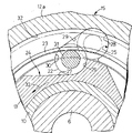
Fig. 3 is the amplification profile that dissects along 3-3 cutting line among Fig. 1;
Fig. 4 is the amplification profile that dissects along 4-4 cutting line among Fig. 1;
Fig. 5 is the transmitting torque performance plot;
Fig. 6 is the load characteristic figure of belleville spring;
Fig. 7 is the longitudinal sectional drawing at main position of the 2nd embodiment's stepless speed variator.
At first at Fig. 1, gear box 5 is connected the side by the motor of not representing among the figure that motorcycle carried, between the bent axle 6 of motor and the stepless speed variator 8 between the output gear 7 on this bent axle 6, installed of free rotary ground supporting relatively, be incorporated in this gear box 5, output gear 7 with figure in not the reduction gear 9 that links to each other of driving wheel of expression be meshed.
On bent axle 6, lining 10 cylindraceous is installed, and is connected with simultaneously main member one input component 12 of stepless speed variator 8 by spline, seize input component 12 on both sides by the arms be tightened in bent axle 6 at the nut 11 of centre head with above-mentioned lining 10.And output gear 7 by lining 10 free rotary ground supportings on bent axle 6, can relatively rotate bent axle 6.
Referring to Fig. 2, stepless speed variator 8 is by constituting with the bottom: the input component 12 that is connected with bent axle 6 splines simultaneously; Around and the output member 13 that rotates freely of input component 12 same axis, be arranged at planet row the 14 and the 1st overrunning clutch 15 between input component 12 and the output member 13; Can around with the Spin Control part 16 of input component 12 same axis rotations; The axis identical with the spin axis of this Spin Control part 16 arranged, be fixed on the gear box 5, as the 2nd overrunning clutch 18 of setting between the stationary axle 17 of fixed block and the Spin Control part 16; Be arranged at above-mentioned planet row's 14 gear ring 36 and the 1st centrifugal clutch 19 between the Spin Control part 16; Be arranged at the 2nd centrifugal clutch 20 between input component 12 and the above-mentioned gear ring 36.
On the input component 12, be provided with coaxial cylindrical part 12a integratedly, between this cylindrical part 12a and output member 13, be provided with the 1st overrunning clutch 15 around output member 13.
At Fig. 3, the 1st overrunning clutch 15 is by output member 13; The cylindrical part 12a of input component 12; A plurality of rollers 22 of arranged spaced along the circumferential direction between output member 13 and cylindrical part 12a; Tying the spring 23 in the outside of each roller 22 together forms.
Inboard reentrant part 24 is made of following several parts: can with interior meshing 26 of roller 22 inner mesh; The one end engaging piece 26 in this of ining succession connects the side (left side of Fig. 3) to output member 13 circumferencial directions simultaneously, as if will change to the interior plane of inclination 27 that the radial outside position equally tilts.Interior engaging piece 26 is circular-arc for it can be contacted with the outer surface of the about quarter turn in inboard of roller 22.
In addition, outside reentrant part 25 is by constituting with the bottom: can accommodate all accommodation sections 28 of roller 22; One end this accommodation section 28 of ining succession connects the side (left side of Fig. 3) to above-mentioned output member 13 circumferencial directions simultaneously, as if will change to the flare inclined-plane 29 that the radially inner side position equally tilts; It can be held roller 22 in the centre under the arm with engaging piece in above-mentioned 26, and the outer gearing portion 30 of flare inclined-plane 29 the other ends of ining succession.And accommodation section 28, as if like will avoiding roller 22 and the outer ring surface of output member 13 contacting, making can be with roller 22 whole shape of accommodating.Outer gearing portion 30 is circular-arc for it can be held roller 22 middle under the arm with engaging piece 26 in above-mentioned.
At the excircle of each roller 22 axial central position, be respectively equipped with the tying groove 31 of ring-type.Spring 23 usefulness spring wire bending formings are made, and under the free state of no external force effect, as if will become like the circle that two ends almost link to each other, and tie up to 31 li of the tying grooves of all rollers 22 from the outside.And when hitching all rollers 22, spring 23 is in the state that its two ends are deviated from.In this state, spring 23 sends and makes each roller rely on the spring force of inboard reentrant part 24 1 sides.
With form, spring 23 is taken in permission with the displacement of moving the spring 23 that is produced of roller 22 annular slot 32 is set on cylindrical part 12a in the inner ring surface upper shed of cylindrical part 12a.
The 1st overrunning clutch 15 like this, shown in arrow among Fig. 3 33 like that, the words that the direction that output member 13 is meshed with roller 22 along the interior engaging piece 26 that makes inboard reentrant part 24 is rotated, the rotating speed of output member 13 be by the state below the setting rotating speed that spring force determined of spring 23 under, roller 22 quilts are held under the arm between the outer gearing portion 30 of the interior engaging piece 26 of inboard reentrant part 24 and outside reentrant part 25, transmission of power is carried out between the cylindrical part 12a of output member 13 and input component 12, and the 1st overrunning clutch 15 is in the state of transferring power.And bent axle 6 to be cylindrical part 12a begin with the words of the rotating speed rotation that surpasses output member 13, the spring force of each roller 22 resistance spring 23, and accommodated by the accommodation section 28 of outside reentrant part 25, cut off the cylindrical part 12a of input component 12 and the transmission of power between the output member 13 thus.
Have, at Fig. 1 and Fig. 2, planet row 14 is made up of following member: sun gear 35 again; Coaxial gear ring 36 around this sun gear; The planet carrier 37 of a plurality of planet wheels 38 that free rotary ground supporting is meshed with sun gear 35 and gear ring 36.Sun gear 35 is connected with the head cylindrical spline of cylindrical part 12a on being positioned at input component 12, and planet carrier 37 is connected with output member 13 in addition, and gear ring 36 is located at an end of cylindrical shell 39 integratedly.
At Fig. 4, the composition member of the 2nd overrunning clutch 18 has: with encircle 41 in the clutch that stationary axle 17 splines are connected; Coaxial in the clutch ring 41, be fixed in the clutch outer shroud 42 of Spin Control part 16 by method such as be pressed into; In clutch between ring 41 and the clutch outer shroud 42, a plurality of rollers 43 of arranged spaced along the circumferential direction; Tie the spring 44 in the outside of each roller 43 together.
In clutch, along the circumferential direction be interval with a plurality of inboard reentrant part 45 on ring 41 outer ring surfaces.The inner ring surface of clutch outer shroud 42 in addition, be with clutch in the outer ring surface of ring 41 in abutting connection with opposed, on the inner ring surface of this clutch outer shroud 42, be provided with and above-mentioned inboard reentrant part 45 corresponding a plurality of outsides reentrant part 46.
The formation of inboard reentrant part 45 is all divided to be had: can with the interior engaging piece 47 of roller 43 inner mesh; One end in succession engaging piece 47 in this, connect a side (left side of Fig. 4) of ring 41 circumferencial directions in clutch simultaneously, as if to change to the interior plane of inclination 48 that the radial outside position equally tilts.Interior engaging piece 47 is circular-arc for it can be contacted with the outer surface of the about quarter turn in inboard of roller 43.
In addition, the component part of outside reentrant part 46: can accommodate all accommodation sections 49 of roller 43; One end this accommodation section 49 of ining succession connects a side (left side of Fig. 4) of ring 41 circumferencial directions in above-mentioned clutch simultaneously, as if will change to the flare inclined-plane 50 that the radially inner side position equally tilts; It can be held roller 43 in the centre under the arm with engaging piece in above-mentioned 47, and the outer gearing portion 51 of the other end on the flare inclined-plane 50 of ining succession.And accommodation section 49 as if will avoid like the outer ring surface of ring 41 in roller 43 and the clutch contacts, making can be with roller 43 whole shape of accommodating.Outer gearing portion 51 is circular-arc for it can be held roller 43 middle under the arm with engaging piece 47 in above-mentioned.
At the cylindrical of each roller 43 axial central position, be respectively equipped with the tying groove 52 of ring-type.Spring 44 usefulness spring wire bending formings are made, and under the free state of no external force effect, as if will become like the circle that two ends almost link to each other, and tie up to 52 li of the tying grooves of all rollers 43 from the outside.And when hitching all rollers 43, spring 44 is in the state that its two ends are deviated from, and in this state, spring 44 sends and makes each roller rely on the spring force of inboard reentrant part 45 1 sides.
With form in the inner ring surface upper shed of clutch outer shroud 42, the displacement of moving the spring 44 that produced of permission along with roller 43 is set on clutch outer shroud 42, and the annular slot 53 of contraction spring 44.
The 2nd overrunning clutch 18 like this, the clutch outer shroud 42 that becomes one with Spin Control part 16, when shown in arrow among Fig. 4 54 like that along opposite with input component 12 directions, when outer gearing portion 51 is rotated with the direction of roller 43 engagements, roller 43 quilts are held under the arm between the interior engaging piece 47 of the outer gearing portion 51 of outside reentrant part 46 and inboard reentrant part 45, to be that Spin Control part 16 is passed to and encircled 41 in the clutch from clutch outer shroud 42 with power, but because of ring 41 in the clutch is connected with stationary axle 17 splines, so the rotation of clutch outer shroud 42 and Spin Control part 16 is prevented.In addition, shown in arrow among Fig. 4 55 like that, clutch outer shroud 42 is during along the direction rotation identical with input component 12, the spring force of each roller resistance spring 44, and being accommodated by the accommodation section 49 of outside reentrant part 46.Thus, clutch outer shroud 42 is that Spin Control part 16 can be around stationary axle 17 idle running.
The 1st centrifugal clutch 19 is by constituting with the bottom:
Be arranged at the outer clutch plate 57 of multi-disc between cylindrical shell 39 and the Spin Control part 16, that cylindrical is connected with cylindrical shell 39 splines, a distolateral tangible all-in-one-piece gear ring 36 of its middle cylinder body 39, and cylindrical shell 39 is around Spin Control part 16.One or more pieces internal clutch sheets 58 that coincidence is disposed between these outer clutch plate 57, circle is connected with Spin Control part 16 splines in the while; The compression plate 59 of opposed with the outside of the outer clutch plate 57 of ragged edge, as to be flush-mounted in cylindrical shell 39 inboard; Be compressed the spring 60 between the outer clutch plate 57 that is installed on the inside and ragged edge; By with inboard opposed retainer 61 free rotary ground supportings of the outer clutch plate 57 of the inside, a plurality of balls 62 of contacting with the flows inside of the outer clutch plate 57 of the inside simultaneously; Be configured in the opposite side of the retainer 61 opposite, the push plate 63 that makes itself and above-mentioned each ball 62 roll and contact with outer clutch plate 57; The opposite side of the push plate 63 opposite with retainer 61,63 opposed with push plate, be made as the lobe plate 64 of one with input component 12; Be arranged at a plurality of centrifugal globes 65 between lobe plate 64 and the push plate 63.And in the one side 5 of lobe plate 64 towards push plate 63, circumferencial direction is arranged at intervals with a plurality of camming surface 64a that equally tilt, make itself and each centrifugal globe 65 to roll and contact in abutting connection with push plate 63 towards the radial outside of lobe plate 64, it feels like.In addition, the back-up ring 83 that is connected with the outer clutch plate 57 of the inside from retainer 61 1 sides is flush-mounted in the inboard of cylindrical shell 39, by the assembling load of these back-up ring 83 decision springs 60.
The 1st centrifugal clutch 19 like this, because input component 12 is the rotation of lobe plate 64, centrifugal action is just arranged on each centrifugal globe 65, along with its action of centrifugal force, centrifugal globe 65 moves to the radial outside position of lobe plate 64 along camming surface 64a, therefore push plate 63 overcomes the spring force of spring 60, the outer clutch plate 57 inside the pushing.When the pushing force of push plate 63 has overcome the spring force of spring 60, when making the mutual frictional engagement of outer clutch plate and internal clutch sheet 57,58, cylindrical shell 39 is that gear ring 36 just has been connected with Spin Control part 16.And the spring force of spring 60 is set at: when input component 12 is that the rotating speed of lobe plate 64 is the predetermined the 1st when setting rotating speed, rotating speed when for example becoming motorcycle and dispatch a car, by the pushing force that results from push plate 63, make the 1st centrifugal clutch 19 beginning frictional engagement, when change to than the 1st set rotating speed big the 2nd when setting rotating speed, frictional engagement is finished.
The 2nd centrifugal clutch 20 is by constituting with the bottom: from the part of gear ring 36 adjacency of cylindrical shell 39 1 ends, the 1st compression plate 66 that radially stretches out inwards; Vacating on the position the 2nd compression plate 67 that cylindrical is connected with cylindrical shell 39 splines at interval to lobe plate 64 1 sides from the 1st compression plate 66; By a plurality of spin 69 that are disposed at that retainer 68 between the 2nd compression plate 67 and the lobe plate 64 keeps with rotating freely and roll and contact with the 2nd compression plate 67 and lobe plate 64; Be compressed the spring 70 that is arranged between the 1st and the 2nd compression plate 66,67; Might with first compression plate, 66 frictional engagement, opposed with the 1st compression plate 66, the 1st friction plate 71 that is connected with the cylindrical part 12a spline of input component 12 of inner ring simultaneously; Might with the 2nd compression plate 67 frictional engagement, opposed with the 2nd compression plate 67, simultaneously in the 2nd friction plate 72 that is connected with above-mentioned cylindrical part 12a spline of circle; In vacating at interval position from the 1st friction plate 71 to sun gear 35 1 sides, being flush-mounted in the belleville spring 74 that is provided with the check ring 75 of outer surface of cylindrical part 12a and the 1st friction plate 71.And the cylindrical of the 1st friction plate 71 is that liquid seal cooperates with the cylindrical of the 2nd friction plate 72.Between the cylindrical of the 1st and the 2nd friction plate 71,72, be provided with liquid chamber 73.The retaining that links from retainer 68 1 sides and the 2nd compression plate 67 is stored up 84 and is flush-mounted on the cylindrical shell 39 in addition, by the assembling load of these back-up ring 84 decision springs 70.
This 2nd centrifugal clutch 20, because the i.e. rotation of the 1st and the 2nd friction plate 71,72 of input component 12 just has centrifugal action on the Lubricants that remains between two friction plates 71,72, because Lubricants accumulates in liquid chamber 73 1 sides, the pressure of liquid chamber 73 just increases.And because the pressure of liquid chamber 73, be used on two friction plates 71,72 with regard to the masterpiece that has direction to deviate from mutually, when this makes every effort to overcome the spring force of clothes belleville spring 74, when moving it the 1st friction plate 71 and the 1st compression plate 66 frictional engagement, the 2nd friction plate 72 also with the 2nd compression plate 67 frictional engagement, cylindrical shell 39 is that to store up 36 be that input component 12 just has been connected with cylindrical part 12a to tooth.And the spring force of belleville spring 74 is set at: when the rotating speed of input component 12 change to setting ratio the 1st centrifugal clutch 19 the 2nd set rotating speed high the 3rd when setting rotating speed, owing to result from the pushing force of the 1st friction plate 71, the 2nd centrifugal clutch 20 beginning frictional engagement; When change to than the 3rd set rotating speed big the 4th when setting rotating speed, frictional engagement is finished.
, for make and this lobe plate 64 between form Lubricants storeroom 77, and on lobe plate 64 mounting cover 78.The Lubricants oil duct 79 that is arranged on gear box 5 and the stationary axle 17 is communicated with Lubricants storeroom 77, is provided with the Lubricants in the Lubricants storeroom 77 is directed into the fuel feeding oil duct 81 between the circle in the 1st and the 2nd friction plate 71,72 on input component 12.
Following one side makes an explanation to this 1st embodiment's effect on one side with reference to Fig. 5.By among the figure not expression starting arrangement started rotatablely moves, by output gear 7, the output member of passing to the 1st overrunning clutch 15 like that 13 shown in arrow among Fig. 3, the direction rotation that output member 13 is meshed with roller 22 along the interior engaging piece 26 that makes inboard reentrant part 24, by the state below the setting rotating speed that spring force determined of spring 23, roller 22 quilts are held under the arm between the interior engaging piece 26 of the outer gearing portion 30 of outside reentrant part 25 and inboard reentrant part 24, and transmission of power can not be carried out between the cylindrical part 12a of counterrotating input component 12 at output member 13 with to bent axle 6.Promptly the 1st overrunning clutch 15 is in the transferring power state, is input to bent axle 6 from the power of above-mentioned starting arrangement, and motor has just been started.On the other hand, planet row 14, along with power is delivered to input component 12 by the 1st overrunning clutch 15 from output member 13, sun gear 35 and the rotation of planet carrier 37 one, so gear ring 36 also with sun gear 35 and planet carrier 37, rotate along same direction simultaneously, but the rotating speed of input component 12 at this moment is because of lower than the 1st setting rotating speed with input component 12, so the 1st centrifugal clutch 19 is in the power cut state, gear ring 36 idle running.
And begin words as motor is started, bent axle 6 is input component 12 cylindrical part 12a with the rotating speed rotation that surpasses output member 13 rotating speeds, at the 1st overrunning clutch 15, each roller 22 overcomes the spring force of spring 23, has been accommodated 28 li of the accommodation sections of outside reentrant part 25.Therefore, the transmission of power of being undertaken by the 1st overrunning clutch 15 is cut off, and does not pass to output member 13 from the rotating power of bent axle 6.
If engine speed rises to the words of the 1st above setting rotational speed N 1 of idling speed, along with sun gear 35 and input component 12 together rotate, gear ring 36 is that cylindrical shell 39 passes through planet wheel 38, and along rotating in the opposite direction with input component 12 sides, the 1st centrifugal clutch 19 begins to do in conjunction with action simultaneously.Therefore, pass to Spin Control 16 with the corresponding rotating power opposite of the combination force size of the 1st centrifugal clutch 19 with input component 12 directions, but rotation opposite with input component 12 directions, Spin Control part 16, stoped by the 2nd overrunning clutch 18, cylindrical shell 39 is that the rotation in tooth grain bin 36 has been braked.Therefore, gear ring 36 quilts have been braked accordingly with the size of the combination force of the 1st centrifugal clutch 19, planet row 14, corresponding with the rotational speed of gear ring 36, planet carrier 37 is along being the identical direction rotation of input component 12 with sun gear 35, the combination force of the 1st centrifugal clutch 19 that changes with the rotational speed variation of following input component 12 changes corresponding, and changes gear ratio, and the transmitting torque between input component 12 and the output member 13 increases with the rotating speed of input component 12.
The rotating speed of input component 12 further increases, and the 2nd frictional engagement power of setting rotational speed N 2, the 1 centrifugal clutches 19 that reaches reaches maximum, and the rotation of gear ring 36 stops fully.Therefore, rotating power has passed to output member 13 to be arranged 14 determined certain gear ratio by planet from input component 12, and power has been passed to output member 13 with being directly proportional with engine speed.This is that situation during with the motorcycle low speed driving is corresponding.
The turn up the 2nd of input component 12 is set rotational speed N the 3rd more than 2 setting rotational speed N 3, the 2 centrifugal clutches and is begun to do in conjunction with action.Input component 12 and gear ring 36, be connected accordingly with the size of the combination force of the 2nd centrifugal clutch 20, gear ring 36 is along the direction rotation identical with input component 12, so the combination force of the 2nd centrifugal clutch 20 that changes with the rotational speed variation of following input component 12 changes accordingly, while change gear ratio rotating power has been passed to output member 13.At this moment, the 1st centrifugal clutch 19 also is in bonding state, but because of allowing Spin Control part 16 along the direction rotation identical with input component 12, so gear ring 36 is along also just licensed with the rotation of input component 12 equidirectionals.
The rotating speed of input component 12 reaches the 3rd to be set rotational speed N the 4th 3 or more and sets rotational speed N 4, and the frictional engagement of the 2nd centrifugal clutch 20 finishes, and gear ring 36 and cylindrical shell 39 just become one with input component 12, rotate along same direction.And along with sun gear 35 and gear ring 36 rotatablely move integratedly with input component 12, by planet row 14, input component 12 and output member 13 also become one and have rotated.This is that situation when running at high speed with motorcycle is corresponding.
But the load characteristic of the belleville spring 74 of the 2nd centrifugal clutch as shown in Figure 6, is being defined as maximum load under the situation of erection load, and when the frictional engagement of the 2nd centrifugal clutch 20 was finished, the load on spring of belleville spring 74 was lower than erection load.Therefore when slowing down, as shown in phantom in Figure 5, the state when running at high speed lasts till that always rotating speed becomes than till the low rotating speed of the 4th setting rotational speed N 4.
Like this, in following stepless speed variator 8 of the present invention, because of input component 12 and output member 13 are configured on the same axis, thus can make compact structure, and compare with the stepless speed variator that used belt in the past, can improve its durability.When low speed, can obtain the 14 common transmission efficiencies that obtained in addition, when high speed, can obtain directly to connect the high transmission efficiency of input component 12 and output member 13 by planet row.
Fig. 7 is the 2nd an embodiment's of the present invention schematic representation, is being marked with identical label with the corresponding part of above-mentioned the 1st embodiment.
Be arranged at the 2nd centrifugal clutch 20 between input component 12 and the gear ring 36 ': the 1st compression plate 66 that radially stretches out inwards from cylindrical shell 39 by constituting with the bottom; The 2nd compression plate 67 that cylindrical is connected with cylindrical shell 39 splines; Keep by retainer 68 with rotating freely, and a plurality of balls 69 that contact with the 2nd compression plate 67 and lobe plate 64 rollings; Be compressed the spring 70 that is arranged between two compression plates 66,67; With the 1st compression plate 66 opposed the 1st friction plates 71; With the 2nd compression plate 67 opposed the 2nd friction plates 72 '; Send and make the belleville spring 74 of the 1st friction plate 71 near the spring force of the 2nd friction plate 72 ' direction.
The 2nd friction plate 72 ' interior circle be connected with the cylindrical spline of input component 12 cylindrical part 12a.In addition, the interior circle of the 1st friction plate 71 and the 2nd friction plate 72 ' interior round spline be connected, the cylindrical of the 1st friction plate 71 and the 2nd friction plate 72 ' cylindrical be that liquid seal cooperates, between the cylindrical of the 1st and the 2nd friction plate 71,72, be provided with liquid chamber 73.In addition the 2nd friction plate 72 ' the interior circle outside be embedded with check ring 75, store up between the 75 and the 1st friction plate 71 at this spring catch and be provided with belleville spring 74.
This 2nd embodiment, when the stepless speed variator overall package, can with the 1st friction plate the 71, the 2nd friction plate 72 ', belleville spring 74 and check ring 75 be as the assembly parts assembled in advance, can help the raising of assembling work efficient.
More than explained embodiments of the invention, but the present invention is not limited to the foregoing description, the present invention who does not depart from claims to be put down in writing can carry out various changes designs.
As foregoing, stepless speed variator of the present invention is by constituting with the bottom: input component; Around the output member that rotates freely with this input component same axis; Arrange by the planet that planet carrier free rotary ground supporting, while planet carrier are connected with output member with the planet wheel that sun gear that is connected with input component and gear ring are meshed; The Spin Control part that the spin axis identical with input component arranged; Prevent above-mentioned Spin Control part to allow the Spin Control part to the direction rotation identical and be arranged at overrunning clutch between Spin Control part and the fixed block along the direction rotation opposite with the input component sense of rotation with the input component sense of rotation; Set rotating speed and begin combination along with the rotating speed of input component reaches the 1st, make simultaneously its rotating speed at input component reached than the 1st set rotating speed big the 2nd when setting rotating speed in conjunction with finishing, and be arranged at the 1st centrifugal clutch between above-mentioned gear ring and the Spin Control part; Along with reaching than the 2nd, the rotating speed of input component sets big the 3rd the setting rotating speed and begin combination of rotating speed, make simultaneously its rotating speed at input component reached than the 3rd set rotating speed big the 4th when setting rotating speed in conjunction with finishing, and be arranged at the 2nd centrifugal clutch between input component and the gear ring.So, can make input component and output member are configured in compact structure on the same axis, compare with the stepless speed variator that used belt in the past, can improve its durability, obtain higher transmission efficiency.
Claims (1)
1. a stepless speed variator between input side and outlet side, can infinitely change gear ratio ground and carry out transmission of power, it is characterized in that it comprises: input component (12); The output member (13) that rotates freely around the axis identical with this input component (12); The planet wheel (38) that sun gear (35) that is connected with same input component (12) and gear ring (36) are meshed is by planet carrier (37) supporting rotatably freely, the planet row (14) that while planet carrier (37) is connected with output member (13); The Spin Control part (16) that the spin axis identical with input component (12) arranged; Prevent above-mentioned Spin Control part (16) along the direction rotation opposite with input component (12) sense of rotation, and allow Spin Control part (16), and be arranged at the overrunning clutch (18) between Spin Control part (16) and the fixed block (17) to the direction rotation identical with input component (12) sense of rotation; Set rotating speed and begin combination along with the rotating speed of input component (12) reaches the 1st, make simultaneously its rotating speed at input component (12) reached than the 1st set rotating speed big the 2nd finish combination when setting rotating speed, and be arranged at the 1st centrifugal clutch (19) between above-mentioned gear ring (36) and the Spin Control part (16); Along with reaching than the 2nd, the rotating speed of input component (12) sets big the 3rd the setting rotating speed and begin combination of rotating speed, make simultaneously its rotating speed at input component (12) reached than the 3rd set rotating speed big the 4th finish combination when setting rotating speed, and be arranged at the 2nd centrifugal clutch (20,20 ') between input component (12) and the gear ring (36).
Applications Claiming Priority (3)
| Application Number | Priority Date | Filing Date | Title |
|---|---|---|---|
| JP122517/95 | 1995-05-22 | ||
| JP122517/1995 | 1995-05-22 | ||
| JP12251795A JP3605436B2 (en) | 1995-05-22 | 1995-05-22 | Continuously variable transmission |
Publications (2)
| Publication Number | Publication Date |
|---|---|
| CN1136651A CN1136651A (en) | 1996-11-27 |
| CN1066524C true CN1066524C (en) | 2001-05-30 |
Family
ID=14837818
Family Applications (1)
| Application Number | Title | Priority Date | Filing Date |
|---|---|---|---|
| CN96100269A Expired - Fee Related CN1066524C (en) | 1995-05-22 | 1996-05-20 | Stepless transmitter |
Country Status (4)
| Country | Link |
|---|---|
| JP (1) | JP3605436B2 (en) |
| KR (1) | KR0185772B1 (en) |
| CN (1) | CN1066524C (en) |
| MY (1) | MY117597A (en) |
Families Citing this family (16)
| Publication number | Priority date | Publication date | Assignee | Title |
|---|---|---|---|---|
| KR100276912B1 (en) * | 1996-12-31 | 2001-02-01 | 정몽규 | Friction member of automatic transmission |
| AUPQ089799A0 (en) * | 1999-06-10 | 1999-07-01 | Aimbridge Pty Ltd | Transmission |
| TW496932B (en) * | 2000-03-30 | 2002-08-01 | Honda Motor Co Ltd | Power transmission device for a small-sized vehicle |
| KR20010112175A (en) * | 2001-11-16 | 2001-12-20 | 이종은 | Device for constructing a pipe in using a boiler |
| CN100338376C (en) * | 2004-07-09 | 2007-09-19 | 上汽集团奇瑞汽车有限公司 | Power shifting driving device for infinite variable speed mechanism |
| CN102661367B (en) * | 2005-11-11 | 2014-09-17 | 吴志强 | Compound planetary transmission stepless speed changer |
| CN101349310B (en) * | 2008-09-01 | 2011-04-27 | 重庆大学 | Planetary type main clutch for automobile |
| CN101839312B (en) * | 2009-03-19 | 2013-01-02 | 本田技研工业株式会社 | Vehicular automatic transmission with planetary gear mechanism |
| CN101839314B (en) * | 2009-03-19 | 2012-11-14 | 本田技研工业株式会社 | Automatic transmission equipped with planetary gear mechanisms |
| CA2764064C (en) * | 2009-06-04 | 2014-08-12 | The Hilliard Corporation | Drive clutch for a continuously variable transmission with engine braking and built in belt protection |
| CN102261440B (en) * | 2011-08-01 | 2013-09-25 | 魏波 | Continuously variable transmission |
| CN103256353B (en) * | 2013-04-28 | 2015-08-12 | 河南科技大学 | Double planet wheel rows of mixing convergent current type multi-clutch speed change gear |
| CN103277469B (en) * | 2013-04-28 | 2015-07-15 | 河南科技大学 | Planet busbar type multi-shaft clutch speed-changing device |
| CN106838154B (en) * | 2016-12-14 | 2019-01-01 | 山推工程机械股份有限公司 | A kind of manual transmission |
| US10683920B2 (en) * | 2018-10-23 | 2020-06-16 | Atieva, Inc. | Torque limiter for use with a dual planetary/integrated differential drive train |
| US11005337B2 (en) | 2018-10-23 | 2021-05-11 | Atieva, Inc. | Removable differential for an active core electric motor |
Citations (3)
| Publication number | Priority date | Publication date | Assignee | Title |
|---|---|---|---|---|
| US4128023A (en) * | 1976-07-19 | 1978-12-05 | Trw Inc. | Coupling apparatus |
| SU1569468A1 (en) * | 1987-09-03 | 1990-06-07 | Белорусский Политехнический Институт | Vehicle planetary gear-box |
| CN1055805A (en) * | 1991-04-22 | 1991-10-30 | 张德贵 | A kind of stepless speed changing mechanism of machinery |
-
1995
- 1995-05-22 JP JP12251795A patent/JP3605436B2/en not_active Expired - Fee Related
-
1996
- 1996-05-17 MY MYPI96001883A patent/MY117597A/en unknown
- 1996-05-20 CN CN96100269A patent/CN1066524C/en not_active Expired - Fee Related
- 1996-05-22 KR KR1019960017544A patent/KR0185772B1/en not_active IP Right Cessation
Patent Citations (3)
| Publication number | Priority date | Publication date | Assignee | Title |
|---|---|---|---|---|
| US4128023A (en) * | 1976-07-19 | 1978-12-05 | Trw Inc. | Coupling apparatus |
| SU1569468A1 (en) * | 1987-09-03 | 1990-06-07 | Белорусский Политехнический Институт | Vehicle planetary gear-box |
| CN1055805A (en) * | 1991-04-22 | 1991-10-30 | 张德贵 | A kind of stepless speed changing mechanism of machinery |
Also Published As
| Publication number | Publication date |
|---|---|
| JP3605436B2 (en) | 2004-12-22 |
| JPH08312737A (en) | 1996-11-26 |
| CN1136651A (en) | 1996-11-27 |
| KR960041801A (en) | 1996-12-19 |
| KR0185772B1 (en) | 1999-04-01 |
| MY117597A (en) | 2004-07-31 |
Similar Documents
| Publication | Publication Date | Title |
|---|---|---|
| CN1066524C (en) | Stepless transmitter | |
| CN1081764C (en) | Differential gear | |
| US6461268B1 (en) | Continuously variable transmission device | |
| US8409039B2 (en) | Dual stage clutch | |
| CN1087818C (en) | Automatic speed variator | |
| EP1436529A1 (en) | An improved continuously variable transmission device | |
| CN1307985A (en) | Stepless speed variator for vehicle | |
| CN1095955C (en) | Metal V-belt type continuously variable transmission | |
| CN1657798A (en) | Centrifugal clutch | |
| CN1690474A (en) | V-belt type automatic transmission | |
| CN1312186A (en) | V-shape belt type automatic speed-variator for vehicles | |
| CN1066716A (en) | Adopt the limited-slip differential of bevel pinion | |
| EP0851149A1 (en) | A planetary gear mechanism | |
| WO2021110155A1 (en) | Fully-mechanical self-adaptive automatic transmission | |
| CN1290824A (en) | Friction clutch, automobile speed changer, power distributor and power transfer device | |
| CN1301929A (en) | Lubricating oil supply device for stepless speed changer | |
| JP2015505599A (en) | Power transmission device for electric vehicle with continuously variable transmission | |
| CN1957195A (en) | Ball gear for transmitting rotation | |
| CN1301644A (en) | Power system for automatic speed changer | |
| CN1043673A (en) | Automatic bicycle speed variator | |
| CN110206861A (en) | The speed changer of override type shift | |
| CN111016643B (en) | Double-helix double-surpassing integrated intelligent self-adaptive electric drive precursor system | |
| US6203466B1 (en) | Continuously variable transmission apparatus | |
| CN1223775C (en) | Power transmission device with stepless variable speed mechanism | |
| JP4085457B2 (en) | Continuously variable transmission |
Legal Events
| Date | Code | Title | Description |
|---|---|---|---|
| C10 | Entry into substantive examination | ||
| SE01 | Entry into force of request for substantive examination | ||
| C06 | Publication | ||
| PB01 | Publication | ||
| C14 | Grant of patent or utility model | ||
| GR01 | Patent grant | ||
| C19 | Lapse of patent right due to non-payment of the annual fee | ||
| CF01 | Termination of patent right due to non-payment of annual fee |