CN1065936C - Discharger of household water filler - Google Patents
Discharger of household water filler Download PDFInfo
- Publication number
- CN1065936C CN1065936C CN96104388A CN96104388A CN1065936C CN 1065936 C CN1065936 C CN 1065936C CN 96104388 A CN96104388 A CN 96104388A CN 96104388 A CN96104388 A CN 96104388A CN 1065936 C CN1065936 C CN 1065936C
- Authority
- CN
- China
- Prior art keywords
- jet
- crosspoint
- water
- chamber
- pipeline
- Prior art date
- Legal status (The legal status is an assumption and is not a legal conclusion. Google has not performed a legal analysis and makes no representation as to the accuracy of the status listed.)
- Expired - Fee Related
Links
Images


Classifications
-
- D—TEXTILES; PAPER
- D06—TREATMENT OF TEXTILES OR THE LIKE; LAUNDERING; FLEXIBLE MATERIALS NOT OTHERWISE PROVIDED FOR
- D06F—LAUNDERING, DRYING, IRONING, PRESSING OR FOLDING TEXTILE ARTICLES
- D06F39/00—Details of washing machines not specific to a single type of machines covered by groups D06F9/00 - D06F27/00
- D06F39/02—Devices for adding soap or other washing agents
- D06F39/028—Arrangements for selectively supplying water to detergent compartments
-
- D—TEXTILES; PAPER
- D06—TREATMENT OF TEXTILES OR THE LIKE; LAUNDERING; FLEXIBLE MATERIALS NOT OTHERWISE PROVIDED FOR
- D06F—LAUNDERING, DRYING, IRONING, PRESSING OR FOLDING TEXTILE ARTICLES
- D06F39/00—Details of washing machines not specific to a single type of machines covered by groups D06F9/00 - D06F27/00
- D06F39/08—Liquid supply or discharge arrangements
- D06F39/088—Liquid supply arrangements
Abstract
Water feed equipment is provided for an appliance operable with water comprising two valve-controlled water inlets operable at a time to direct a respective jet of water towards the entrance of a respective one of two collecting channels and operable in common to direct respective jets of water toward a point of intersection for formation of a jet toward the entrance of a third collecting channel, and a further valve-controlled water inlet operable by itself to direct a respective water jet toward the entrance of a fourth channel and operable in common with one of the first two jets to direct a jet toward a point of intersection with the jet from that one inlet for formation of a further resultant jet which is directed towards the entrance of a fifth collecting channel.
Description
The present invention relates to a kind of housed device of water filling, especially the water delivery device of the washing agent-jetter in the washing machine, this device has plural program control inlet valve, per two inlet valves are a pair of, its exit end face is controlled inlet valve respectively to the jet crosspoint, makes its direct jet aim at an inlet of collecting pipeline respectively, and, form a synthesizing jet-flow of aiming at intermediate collection pipeline inlet to the inlet valve centralized Control.
In German prospectus 1913868, put down in writing a kind of like this water delivery device.In this device, the mutual angle setting of the outlet of two controlled inlet valves should make it respectively or realize above-mentioned effect during centralized Control.When this situation, utilize one of formed synthesizing jet-flow flushing to be arranged on washing agent--the soft detergent chamber of jetter below the water delivery device, if in washing agent one jetter, must be provided with another washing agent chamber, then just must be provided with the inlet valve that another is directly supplied with this chamber.
Be used for other purpose according to DE3822392A1 in clean water shunting, rather than during flushing washing agent chamber, need to adopt another clean water valve usually; In any case this is because clean water is shunted the conveying that all can disturb the clean water of washing agent chamber according to DE3822392A1.So this known clean water shunting is proved to be unfavorable.Have only by another special-purpose inlet and could control reliably clean water route.
The objective of the invention is, adopt a kind of configuration in the water delivery device of when this specification begins, mentioning, in this configuration, can control five clean water routes at least by three inlet valves.
The measure that realizes this purpose according to the present invention is, one of them direct jet constitutes the crosspoints that another back is connected to three collection pipelines with a jet of another inlet valve on flowing to and after the crosspoint of direct jet.Can collect pipeline to five respectively with three inlet valves like this supplies water.Also can consider further to improve the operating efficiency of operation principle that DE1913868A1 puts down in writing, for example control seven collection pipelines respectively or be used for five inlet valves and control nine collection pipelines respectively with four inlet valves.Owing to when forming synthesizing jet-flow, also can produce spuious jet, this spuious jet will be collected by adjacent collection pipeline, so the order of connection of inlet valve must make spuious jet can only arrive the collection pipeline that those are attached troops to a unit and have started in advance according to washing machine procedure to its chamber.
In view of the above, the preferred design of water delivery device of the present invention is, has three controlled inlet valves, and the outlet of the 3rd valve wherein and the collection pipeline of a direct jet lead to a back jointly and be connected to three second crosspoints of collecting pipelines.In the case, can be the synthesizing jet-flow in second crosspoint soft detergent chamber of attaching troops to a unit, its flushing is not needed to resemble high pressure flushing pre-wash agent chamber and the main washing agent chamber, must be higher than flushing pressure to the flushing pressure of the powder shape washing agent of pre-wash agent chamber and main washing agent chamber to being exactly the soft detergent of liquid originally, when indoor soft detergent is washed, only need to improve liquid level, make it be higher than baffle plate or siphon slope.Collected the spuious jet that pipeline is collected by two other, for example only be used to wash the chamber of having washed in advance (for example pre-wash chamber or smart washing chamber) or be connected on clean water route, directly lead in the alkali liquor container.
At washing agent of the present invention--in the effective design of the device of flusher, having the washing agent that is used to deposit artificial dosage--the back wall of the cover part of the cabinet of the washing agent drawer of four chambers of deal, be provided with four pipe joints, two adjacent pipe joints wherein are in acute angle, aim at first crosspoint, this crosspoint is positioned at the free air crack scope of anti-suction.Though this configuration itself has been known and general, this is configured in is to be used for cooperating the formation back to be connected to three second crosspoints of collecting pipelines with the outlet of the 3rd valve here.
The useful especially design of this washing agent--flusher is, the intermediate collection pipeline in first crosspoint on cover part leads to a distributor chamber that has a spray-hole of the bleaching agent chamber that is used for being provided with in its lower section, be used to collect from the 3rd pipe joint of the direct conveying clean water of a pipe joint and be used to collect to collect pipeline lead to second crosspoint from another of the direct jet of another pipe joint, its another waterline is that collection pipeline and its outlet of the 4th pipe joint is three collection pipelines, each bar is collected pipeline a distributor chamber that has a spray-hole, and this distributor chamber is used for other three settings washing agent chamber thereunder.Owing to only just can supply water for five outlets with three inlet valves, Gu the design cost of this washing agent one flusher is extremely cheap, four outlets wherein are used to the washing agent chamber of washing agent drawer to supply water, and the 5th outlet is used to the alkali liquor container of this washing machine directly to carry clean water, and it is for example pre-installed from one that the clean water that alkali liquor container is filled in advance is used to soak rapidly--the clothing that the load hole of washing machine is packed into.
Owing to utilized branch road, jet water route operation principle (by the synthetic jet of the water jet that intersects) and adopted the jet water route Lu Cha of two serial connections, thereby made the controlled water route quantity increase to five.These five water routes can be used for washing four chambers and can be used for alkali liquor container is directly supplied water.Each chamber that is provided disposes and branch off on jet water route road and affiliated water route should make the water of loss when utilizing jet water route road trouble enter direct path, and it is indoor to introduce prior each of having washed.To in these five clean water routes wherein three directly there is no the damage by water lost territory and control by handling a certain inlet valve.In water route and distribution system, had better not contain moving member (but originally just the inlet valve of needs except).Thereby can fear and break down.Control to five water routes simultaneously of the present invention can realize independent and soaking clothing that not influenced by program step by direct water filling in the washing machine alkali liquor container.
To contrast accompanying drawing below is described further operation principle of the present invention and embodiment.
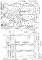
Fig. 1 is inlet valve and clean water water route connection layout;
Fig. 2 is the connection table of operation principle shown in Figure 1;
Fig. 3 is the washing agent that is used to have a washing agent drawer according to inventive principle shown in Fig. 1--the design example of the cover part of flusher;
Fig. 4 one has the vertical view of the washing agent drawer of four washing agent chambers.
The inventive principle of explaining in Fig. 1 has illustrated the conveying of the clean water of entrance pipe E with schematic form, and entrance pipe is connected with valve group V.In valve group V, be provided with electrically-controlled valve, 1 to 3, its outlet 4 to 6 is connected on the water delivery device 7 of the present invention.Meet in outlet 5 and 6 and first crosspoint 8, and on first crosspoint, be connected to and collect pipeline A3 and A5, and a bypass line 9.Valve 1 and 2 or valve 2 and 3 when connecting simultaneously has collection the collection pipeline A4 and the A5 of 10 or 8 synthesizing jet-flows that form in the crosspoint respectively.So on direct path, the roughly the same jets of two intensity are bump and form synthesizing jet-flow mutually in the crosspoint always, synthesizing jet-flow meets with collection pipeline A4 or A5 in the middle of being arranged on.At this moment the flow of synthesizing jet-flow approximately is 50% of two input jet flows, and the assignment of traffic of surplus is given the spuious jet of collecting each about half (consulting Fig. 2) on two adjacent tubes.In order to realize different purposes, in particular for from washing agent one flusher from least four indoor when washing agent is flushed out, five clean waters outlets of collecting pipeline A1 to A5 are used.
For this reason, Fig. 2 illustrates a connection table, and from then on table can be understood, and when according to figure, during one or two opening of valves in the valve of setting, has how many clean waters and certain to collect pipeline and meets.Give in the table when being used for washing agent one flusher, the clean water route of certain bar can be the suggestion of which washing agent chamber water supply.Wherein, pre-wash agent chamber VWK is connected with collection pipeline A1, and main washing agent chamber is connected with collection pipeline A2 and free pipe joint 15 (Fig. 3) is connected with collection pipeline A3.These collect all direct jets that pipeline is respectively applied for the outlet of collecting a valve in the valve 1 to 3.
The washing agent that impinges upon the pre-installed washing machine shown in Fig. 3 and Fig. 4 is washed drawer, and the corresponding embodiment of the water delivery device of signal statement in Fig. 1 is illustrated.Be contained in the cabinet at the washing agent drawer of overlooking shown in Fig. 4, so do not elaborate, the cabinet above the drawer that pushes is by cover part 16 (Fig. 3) closure that is equipped with hollow chamber.Washing agent drawer 17 contains four washing agent chambers that are used for artificial dosage washing agent one deal, the pre-wash agent chamber (VWK) that promptly is used for the pre-wash agent, the main washing agent chamber (HWK) that is used for main washing agent is used for the soft detergent chamber (WSK) of soft detergent and is used for the bleaching agent chamber (BK) of bleaching agent.When washing agent drawer 17 was pushed in the cabinet, the washing agent chamber was positioned at the distributor chamber (VKH) with the main washing agent of distributor chamber (VKV) of the pre-wash agent of its identical setting, the below of the distributor chamber (VKB) of distributor chamber of soft detergent (VKW) and bleaching agent.The washing agent chamber that the hole 18 of the clean water of carrying on each distributor chamber base plate flows under it, and the hollow chamber (not shown) direction flushing rearwards of the indoor washing agent that contains, hollow chamber is connected with alkali liquor container by an elasticity pipeline.
The back wall of cover part 16 is provided with four pipe joints 11 to 15 and 20, and two adjacent pipe joints 12 and 13 wherein are in acute angle, aim at first crosspoint 8, and this crosspoint is positioned at the free air crack scope of anti-suction.This free air crack realizes promptly, an open-work 21 being arranged in the bottom of the pipeline that contains crosspoint 8 in the following way, when being negative pressure in the joint in water supply pipe joint 12 or 13, can replenishing by this open-work and flow into air.Independent pipe joint 11 cooperates with the bypass line 9 that is supplied water by pipe joint 12 and leads to second crosspoint 10, and has the anti-suction hole 22 of oneself.Pipe joint 14 is connected with alkali liquor container at the hollow chamber place that illustrates, and is used for the draining slope air-supply to the washing machine aspiration, this is not done further statement.Thick pipe joint 20 is blind pipe joints of an obstruction, and as standby joint, this is repeated no more.
Inject collection pipeline A1 from the clean water of pipe joint 11, and enter pre-wash agent distributor chamber (VKV) from here.The clean water that only flows to pipe joint 12 is injected collection pipeline A2 by bypass line 9, and enters main washing agent distributor chamber (VKH) from staring at.The clean water that only flows to pipe joint 13 is injected collection pipeline A3, and directly flows to pipe joint 15, has a flexible pipe that leads to alkali liquor container to be connected with this pipe joint, and for example flexible pipe can insert in a scope of packing into of pre-installed washing machine.
10 places meet in the crosspoint to flow to the clean water of pipe joint 11 and 12, and form synthesizing jet-flow 23, and this synthesizing jet-flow is injected and collected in the pipeline A4, and from here soft detergent distributor chamber (VKW) is carried out water filling.The pipe joint 12 and 13 that is added into clean water causes crosspoint 8 with water jet, and forms synthesizing jet-flow 24, and synthesizing jet-flow is injected and collected pipeline A5, and from here bleaching agent distributor chamber (VKB) is carried out water filling.
The present invention is not limited in simplified schematic diagram shown in Figure 1 and the connection table scope in Fig. 2 thereof, and also is not confined in the scope of embodiments described in Fig. 3 and Fig. 4.The present invention is applicable to that a little controlled inlet valve of usefulness of all water fillings will be to the housed device of the water supply of the export pipeline more than three.Also can be extended to four or five inlet valves to the example that has three inlet valves and five export pipelines with the sketch statement among Fig. 1, this can't deviate from basic design of the present invention.Four inlet valves can supply water to seven export pipelines, and five inlet valves can supply water to nine export pipelines.For example when adopting four outside inlet valves, can to the bypass line 9 similar bypass lines of drawing respectively of valve among Fig. 12, two bypass lines are met in the 3rd crosspoint.By that analogy, the connection in the time of also can adopting five inlet valves.Had better not adopt too much inlet valve and crosspoint, this is because this will make the pressure in the collection pipeline with the inlet valve apart from each other become very faint.
In addition, be not limited to the connected mode of embodiment among Fig. 3 and Fig. 4; Because can directly consider to collect other purposes and the configuration of pipeline.If this clean water pipeline can not enter container handling by other water route beyond the common clean water route, also can not adopt pipe joint 15, can allow the water of collecting pipeline A3 directly enter in thereunder the hollow chamber.
Claims (4)
1. the water delivery device of the housed device of a water filling, be particularly useful for the washing agent-jetter in the washing machine, this device has plural program control inlet valve, per two inlet valves constitute a pair of, its exit end face is to the jet crosspoint, inlet valve is controlled respectively, its direct jet is aimed at an inlet of collecting pipeline respectively, and to the inlet valve centralized Control, form one and aim at the jet that the intermediate collection pipeline enters the mouth, it is characterized in that: one of them direct jet on flowing to and in the product crosspoint (8) of this direct jet afterwards forms another back with the jet of another inlet valve (1) and is connected to three crosspoints (10) of collecting pipelines (A1, A2 and A4).
2. device according to claim 1 is characterized in that: 1) be connected on the 2nd back jointly with the bypass line (9) of a direct jet and be connected on the crosspoint (10) of three collection pipelines (A1, A2 and A4).
3. device according to claim 2, it is characterized in that: have four chamber (VWK that are used to deposit washing agent one deal of artificial dosage one, HWK, WSK, cover part (16) back wall (19) of the cabinet of washing agent drawer (17) BK) is provided with four pipe joints (11,12,13 and 15), wherein two adjacent pipe joints (12,13) are in acute angle and aim at the 1st crosspoint (8), and this crosspoint is positioned at the free air crack scope of anti-suction.
4. device according to claim 3 is characterized in that: the intermediate collection pipeline (A5) in first crosspoint (8) on cover part (16) leads to a distributor chamber (VKB) that has a spray-hole of the bleaching agent chamber (BK) that is used to be provided with in its lower section; Be used to collect from the direct jet of a pipe joint (13) wherein one collect pipeline (A3) and lead to the 3rd pipe joint (15) that is used for directly carrying clean water; Be used to collect from the direct jet of another pipe joint (12) and collect pipeline as another of bypass line (9) and lead to second crosspoint (10); Its another feed-line is connected with the 4th pipe joint (11) and its outlet is three and is respectively applied for a distributor chamber (VKV, VKH and VKW) collection pipeline (A1, A2 and A4), distributor chamber has and is used for other three spray-holes (18) that are separately positioned on the washing agent chamber (VWK, HWK and WSK) under it.
Applications Claiming Priority (2)
| Application Number | Priority Date | Filing Date | Title |
|---|---|---|---|
| DE19503589.5 | 1995-02-03 | ||
| DE19503589A DE19503589A1 (en) | 1995-02-03 | 1995-02-03 | Water supply device for a water-bearing household appliance |
Publications (2)
| Publication Number | Publication Date |
|---|---|
| CN1136109A CN1136109A (en) | 1996-11-20 |
| CN1065936C true CN1065936C (en) | 2001-05-16 |
Family
ID=7753133
Family Applications (1)
| Application Number | Title | Priority Date | Filing Date |
|---|---|---|---|
| CN96104388A Expired - Fee Related CN1065936C (en) | 1995-02-03 | 1996-02-03 | Discharger of household water filler |
Country Status (11)
| Country | Link |
|---|---|
| EP (1) | EP0725182B1 (en) |
| KR (1) | KR100401360B1 (en) |
| CN (1) | CN1065936C (en) |
| AT (1) | ATE184664T1 (en) |
| BR (1) | BR9600313A (en) |
| DE (2) | DE19503589A1 (en) |
| ES (1) | ES2139136T3 (en) |
| GB (1) | GB2297561B (en) |
| HK (1) | HK70397A (en) |
| PL (1) | PL312542A1 (en) |
| TR (1) | TR199600087A2 (en) |
Families Citing this family (53)
| Publication number | Priority date | Publication date | Assignee | Title |
|---|---|---|---|---|
| KR200141008Y1 (en) * | 1996-09-30 | 1999-05-15 | 대우전자주식회사 | The water supplying apparatus of a washing machine |
| IT1295908B1 (en) * | 1997-10-31 | 1999-05-28 | T & P Spa | DEVICE FOR THE HOUSING OF WASHING AGENTS IN A WASHING MACHINE WITH INCORPORATED AIR JUMP |
| GB2353540B (en) * | 1999-07-26 | 2003-01-22 | Aweco Appliance Sys Gmbh & Co | Inflow device for water carrying appliances |
| KR100480726B1 (en) * | 2002-11-26 | 2005-04-07 | 엘지전자 주식회사 | Washing machine and of the same method |
| ITPN20030034A1 (en) * | 2003-05-28 | 2004-11-29 | Electrolux Home Products Corporatio N N V | WASHING MACHINE WITH INTEGRATED GROUP OF SOLENOID VALVES. |
| CN100370072C (en) * | 2003-10-14 | 2008-02-20 | 杭州神林电子有限公司 | Apparatus for feeding liquid detergent |
| ES2273158T3 (en) * | 2004-05-13 | 2007-05-01 | Electrolux Home Products Corporation N.V. | WASHER WITH INTEGRATED DEVICE FOR WATER DISTRIBUTORS. |
| ES2327638T3 (en) * | 2004-05-25 | 2009-11-02 | Electrolux Home Products Corporation N.V. | CLOTHING WASHING MACHINE WITH IMPROVED WATER DISPENSERS. |
| KR20050118894A (en) * | 2004-06-15 | 2005-12-20 | 삼성전자주식회사 | Washing machine having a detergent feeding device |
| CN100375594C (en) * | 2004-07-16 | 2008-03-19 | 黑龙江省农业科学院盐碱地作物育种研究所 | Endless-track type water conveyance installation capable of traveling |
| EP1652463A1 (en) | 2004-10-29 | 2006-05-03 | Electrolux Home Products Corporation N.V. | Method for dispensing a multicomponent detergent additive in an water-carrying domestic appliance |
| ITUD20050075A1 (en) * | 2005-05-13 | 2006-11-14 | Invensys Controls Italy Srl | DEVICE AND METHOD FOR FEEDING WATER IN A WASHING MACHINE |
| DE102006002400B3 (en) * | 2006-01-17 | 2007-01-11 | Miele & Cie. Kg | A method for dispensing clothes treatment products in a domestic front loading horizontal axis automatic washing machine has a separate chamber for liquid or powder products dispensed during the latter stages of the wash programme |
| DE102007036009A1 (en) * | 2007-07-30 | 2009-02-19 | Miele & Cie. Kg | Einspülvorrichtung for a washing machine and washing machine |
| US9085844B2 (en) * | 2007-11-13 | 2015-07-21 | Electrolux Home Products, Inc. | Sequenced water delivery in an additive dispenser |
| PL2078779T3 (en) * | 2008-01-14 | 2012-02-29 | Electrolux Home Products Corp Nv | Hydraulic system for a laundry washing machine detergent dispenser |
| DE102008039847B4 (en) * | 2008-08-27 | 2013-11-28 | Etimex Technical Components Gmbh | Actuator of a water distribution arrangement of a washing machine |
| IT1391855B1 (en) * | 2008-09-04 | 2012-01-27 | Indesit Co Spa | METHOD AND DEVICE FOR CONVEYING WASHING AGENTS INTO A WASHING MACHINE |
| ES2356796T3 (en) | 2008-10-09 | 2011-04-13 | Candy S.P.A. | DOMESTIC WASHER WITH WASHING AGENTS INJECTION DEVICE EQUIPPED WITH A DIVIDED DISCHARGE LIQUID FLOW. |
| DE102008054997B4 (en) * | 2008-12-19 | 2010-10-14 | BSH Bosch und Siemens Hausgeräte GmbH | Cleaning device with a detergent dispenser |
| EP2241669B1 (en) * | 2009-04-09 | 2014-06-18 | Electrolux Home Products Corporation N.V. | Washing machine with an improved washing/rinsing-liquid inlet circuit |
| KR101466332B1 (en) * | 2009-09-09 | 2014-11-27 | 삼성전자 주식회사 | Washing machine and detergent feeding device of the same |
| CN102031675B (en) * | 2009-09-28 | 2012-01-11 | 杭州神林电子有限公司 | Device for putting liquid detergent |
| US9687135B2 (en) | 2009-12-21 | 2017-06-27 | Whirlpool Corporation | Automatic dishwasher with pump assembly |
| US8746261B2 (en) | 2009-12-21 | 2014-06-10 | Whirlpool Corporation | Rotating drum filter for a dishwashing machine |
| US9918609B2 (en) | 2009-12-21 | 2018-03-20 | Whirlpool Corporation | Rotating drum filter for a dishwashing machine |
| US8667974B2 (en) | 2009-12-21 | 2014-03-11 | Whirlpool Corporation | Rotating filter for a dishwashing machine |
| US9119515B2 (en) | 2010-12-03 | 2015-09-01 | Whirlpool Corporation | Dishwasher with unitary wash module |
| US8627832B2 (en) | 2010-12-13 | 2014-01-14 | Whirlpool Corporation | Rotating filter for a dishwashing machine |
| PL2519676T3 (en) * | 2009-12-30 | 2014-04-30 | Arcelik As | A washing machine comprising a detergent box |
| US9668636B2 (en) | 2010-11-16 | 2017-06-06 | Whirlpool Corporation | Method and apparatus for dishwasher with common heating element for multiple treating chambers |
| US9113766B2 (en) | 2010-11-16 | 2015-08-25 | Whirlpool Corporation | Method and apparatus for dishwasher with common heating element for multiple treating chambers |
| US9034112B2 (en) | 2010-12-03 | 2015-05-19 | Whirlpool Corporation | Dishwasher with shared heater |
| CN102192661B (en) * | 2011-03-15 | 2012-06-27 | 苏州大学 | Water delivery device |
| US9107559B2 (en) | 2011-05-16 | 2015-08-18 | Whirlpool Corporation | Dishwasher with filter assembly |
| US8733376B2 (en) | 2011-05-16 | 2014-05-27 | Whirlpool Corporation | Dishwasher with filter assembly |
| US9265401B2 (en) | 2011-06-20 | 2016-02-23 | Whirlpool Corporation | Rotating filter for a dishwashing machine |
| US9010344B2 (en) | 2011-06-20 | 2015-04-21 | Whirlpool Corporation | Rotating filter for a dishwashing machine |
| US9005369B2 (en) | 2011-06-20 | 2015-04-14 | Whirlpool Corporation | Filter assembly for a dishwasher |
| US20120318296A1 (en) | 2011-06-20 | 2012-12-20 | Whirlpool Corporation | Ultra micron filter for a dishwasher |
| US9861251B2 (en) | 2011-06-20 | 2018-01-09 | Whirlpool Corporation | Filter with artificial boundary for a dishwashing machine |
| US9301667B2 (en) | 2012-02-27 | 2016-04-05 | Whirlpool Corporation | Soil chopping system for a dishwasher |
| US9730570B2 (en) | 2012-05-30 | 2017-08-15 | Whirlpool Corporation | Reduced sound with a rotating filter for a dishwasher |
| US9237836B2 (en) | 2012-05-30 | 2016-01-19 | Whirlpool Corporation | Rotating filter for a dishwasher |
| US9451862B2 (en) | 2012-06-01 | 2016-09-27 | Whirlpool Corporation | Dishwasher with unitary wash module |
| US9833120B2 (en) | 2012-06-01 | 2017-12-05 | Whirlpool Corporation | Heating air for drying dishes in a dishwasher using an in-line wash liquid heater |
| US9532700B2 (en) | 2012-06-01 | 2017-01-03 | Whirlpool Corporation | Dishwasher with overflow conduit |
| US9554688B2 (en) | 2012-10-23 | 2017-01-31 | Whirlpool Corporation | Rotating filter for a dishwasher and methods of cleaning a rotating filter |
| WO2015065300A1 (en) * | 2013-11-01 | 2015-05-07 | Arcelik Anonim Sirketi | A washing machine comprising a cleaning agent dispenser |
| EP3882392A1 (en) | 2016-09-05 | 2021-09-22 | Electrolux Appliances Aktiebolag | A method of using a laundry washing machine and laundry washing machine |
| CN109898292B (en) * | 2017-12-11 | 2022-04-26 | 合肥海尔滚筒洗衣机有限公司 | Water-breakthrough-preventing water flushing waterway and washing machine |
| DE102018124453A1 (en) * | 2018-10-04 | 2020-04-09 | Miele & Cie. Kg | Washing machine |
| CN112301667B (en) * | 2019-08-02 | 2022-07-29 | 青岛海尔洗衣机有限公司 | Additive feeding device and washing machine |
Citations (2)
| Publication number | Priority date | Publication date | Assignee | Title |
|---|---|---|---|---|
| DE2332020A1 (en) * | 1972-06-27 | 1974-01-10 | Nasa | METHOD AND DEVICE FOR APPLYING PROTECTIVE COATINGS TO A SUBSTRATE |
| DE2333689A1 (en) * | 1972-07-11 | 1974-01-31 | Akg Akustische Kino Geraete | HEADPHONES FOR INTERPRETING SYSTEMS, LANGUAGE SCHOOLS AND THE LIKE |
Family Cites Families (5)
| Publication number | Priority date | Publication date | Assignee | Title |
|---|---|---|---|---|
| NL6805834A (en) * | 1968-04-24 | 1969-10-28 | ||
| DE2154238A1 (en) * | 1970-11-17 | 1972-05-18 | Philips Nv | Automatic machine, for example for washing textiles or for washing dishes and the like |
| DE2232020B2 (en) * | 1972-06-30 | 1974-05-30 | Licentia Patent-Verwaltungs-Gmbh, 6000 Frankfurt | Washing machine liquid distributing manifold - has intersecting inlet and outlet spigots joined by reverse flow preventing chamber |
| DE2233689B2 (en) * | 1972-07-08 | 1980-08-14 | Licentia Patent-Verwaltungs-Gmbh, 6000 Frankfurt | Chemical feed mechanism for washing machine - has double inlet valve followed by sprayer contg. air gap |
| DE2305678A1 (en) * | 1973-02-06 | 1974-08-08 | Licentia Gmbh | Washing machine liquid distributing manifold - provided with vent bores interconnecting supply ducts with non-return flow chamber |
-
1995
- 1995-02-03 DE DE19503589A patent/DE19503589A1/en not_active Withdrawn
- 1995-12-21 ES ES95120290T patent/ES2139136T3/en not_active Expired - Lifetime
- 1995-12-21 EP EP95120290A patent/EP0725182B1/en not_active Expired - Lifetime
- 1995-12-21 AT AT95120290T patent/ATE184664T1/en not_active IP Right Cessation
- 1995-12-21 DE DE59506844T patent/DE59506844D1/en not_active Expired - Lifetime
-
1996
- 1996-01-30 PL PL96312542A patent/PL312542A1/en unknown
- 1996-01-30 KR KR1019960001998A patent/KR100401360B1/en not_active IP Right Cessation
- 1996-02-01 TR TR96/00087A patent/TR199600087A2/en unknown
- 1996-02-02 BR BR9600313A patent/BR9600313A/en not_active IP Right Cessation
- 1996-02-02 GB GB9602108A patent/GB2297561B/en not_active Expired - Fee Related
- 1996-02-03 CN CN96104388A patent/CN1065936C/en not_active Expired - Fee Related
-
1997
- 1997-05-29 HK HK70397A patent/HK70397A/en not_active IP Right Cessation
Patent Citations (2)
| Publication number | Priority date | Publication date | Assignee | Title |
|---|---|---|---|---|
| DE2332020A1 (en) * | 1972-06-27 | 1974-01-10 | Nasa | METHOD AND DEVICE FOR APPLYING PROTECTIVE COATINGS TO A SUBSTRATE |
| DE2333689A1 (en) * | 1972-07-11 | 1974-01-31 | Akg Akustische Kino Geraete | HEADPHONES FOR INTERPRETING SYSTEMS, LANGUAGE SCHOOLS AND THE LIKE |
Also Published As
| Publication number | Publication date |
|---|---|
| GB2297561A (en) | 1996-08-07 |
| HK70397A (en) | 1997-06-06 |
| BR9600313A (en) | 1998-01-27 |
| ES2139136T3 (en) | 2000-02-01 |
| EP0725182A1 (en) | 1996-08-07 |
| KR100401360B1 (en) | 2003-12-24 |
| DE19503589A1 (en) | 1996-08-08 |
| PL312542A1 (en) | 1996-08-05 |
| GB2297561B (en) | 1997-03-05 |
| TR199600087A2 (en) | 1996-08-21 |
| KR960031699A (en) | 1996-09-17 |
| EP0725182B1 (en) | 1999-09-15 |
| CN1136109A (en) | 1996-11-20 |
| ATE184664T1 (en) | 1999-10-15 |
| GB9602108D0 (en) | 1996-04-03 |
| DE59506844D1 (en) | 1999-10-21 |
Similar Documents
| Publication | Publication Date | Title |
|---|---|---|
| CN1065936C (en) | Discharger of household water filler | |
| CN1069364C (en) | Washing machine with detergent-adding device | |
| US4801333A (en) | Method of cleaning articles in a tank | |
| EP0338607B1 (en) | Self-cleaning hydromassage system for bath tubs in general | |
| CN101925322B (en) | Method for self-cleaning of continuous dishwasher and corresponding dishwasher | |
| CN102449228A (en) | Washing machine with an improved washing / rinsing-liquid inlet circuit | |
| CN100493437C (en) | Tableware cleaning machine | |
| CN105266745B (en) | Dishwasher | |
| DE19821148A1 (en) | Program-controlled electric domestic appliance, e.g. washing machine, dishwasher etc. | |
| CN1165650C (en) | Detergent dispensing device | |
| DE3102547A1 (en) | Dish-washing machine | |
| DE102006021954B3 (en) | Rinse cycle performing method for e.g. front side loadable house hold dinnerware dishwasher, involves recycling rinsing liquid via conduit systems, where frequency of modulation of volume flow rate lies in range of frequency of systems | |
| EP0916259A1 (en) | Field-spraying apparatus | |
| CN115485429A (en) | Washing machine door and washing machine | |
| CN206630572U (en) | Dish-washing machine | |
| KR890003345Y1 (en) | Apparatus for watering | |
| EP0152893B1 (en) | Dishwashing machine having liquid level control means of the overflow type | |
| DE19752296A1 (en) | Washing machine drum | |
| CN219699828U (en) | Base station and cleaning system | |
| CN211134850U (en) | Water heating pipe outer wall belt cleaning device | |
| CN215163792U (en) | Liquid level control overflow pipeline of continuous oil removal washing equipment | |
| CN207391757U (en) | A kind of new shampooer and scouring of wool system | |
| CN208839169U (en) | A kind of vacuum belt filter spray equipment | |
| US455059A (en) | Wool-washing machine | |
| JP3557755B2 (en) | Toilet bowl with hot water washing device |
Legal Events
| Date | Code | Title | Description |
|---|---|---|---|
| C06 | Publication | ||
| PB01 | Publication | ||
| C10 | Entry into substantive examination | ||
| SE01 | Entry into force of request for substantive examination | ||
| C14 | Grant of patent or utility model | ||
| GR01 | Patent grant | ||
| C19 | Lapse of patent right due to non-payment of the annual fee | ||
| CF01 | Termination of patent right due to non-payment of annual fee |